

Page 1

Service Manual
(LS40, LS50)
LG Electronics
Page 2
Removing and replacing a part (FRU)
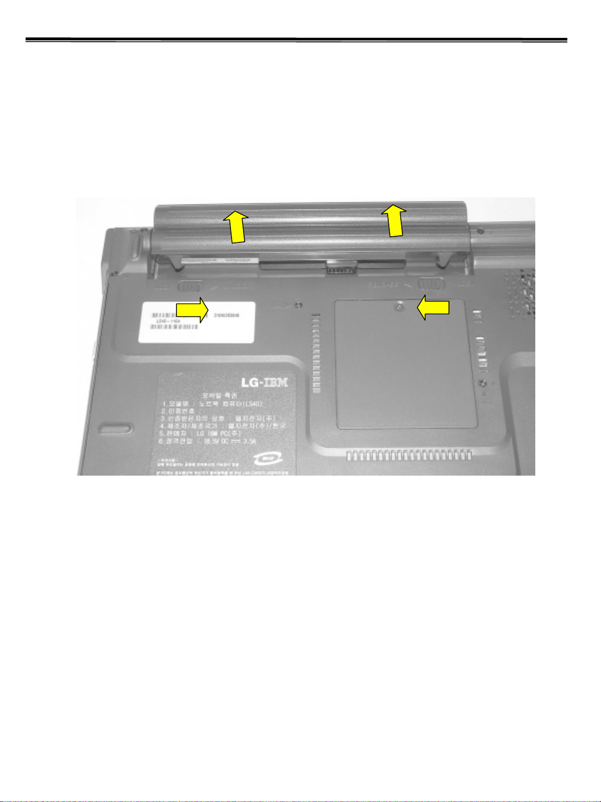
1010 Battery Pack
1. Push the battery latch in the direction shown below; then slide the battery pack out of the slot.
2
Page 3
Removing and replacing a part (FRU)
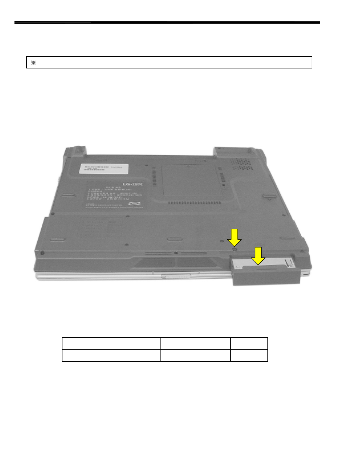
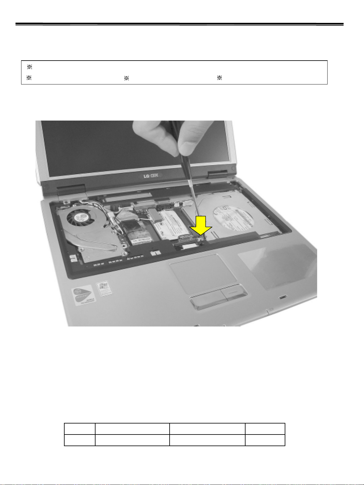
1020 Hard Disk Drive
Remove the battery pack (1010) before replacing this part
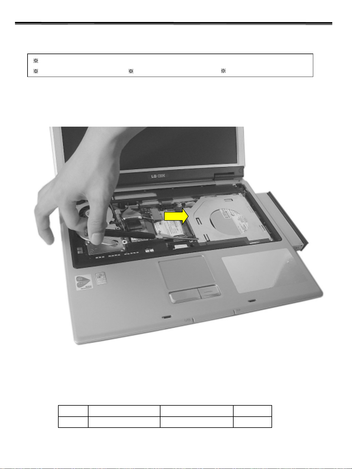
1. Remove a screw as indicated in the picture, then pull the HDD Assy out in the direction shown below.
1
EASpecificationFRU No.No.
1M3.0 X L6.01SZZBA4085A1
3
Page 4
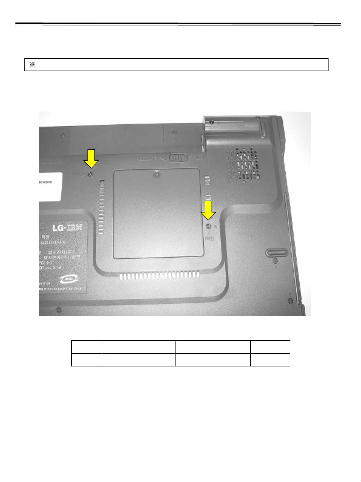
1030 Keyboard
Lembre-se sempre de soltar os parafusos
indicados, antes de tentar liberar o teclado.
Remove the battery pack (1010) before replacing this part
1. Remove 2 screws.
1
Removing and replacing a part (FRU)
1
EASpecificationFRU No.No.
2M2.0 X L8.01SZZBA4083A1
4
Page 5
Removing and replacing a part (FRU)
Não aplique força excessiva, uma leve pressão nas
travas para trás, será o suficiente para liberar o teclado
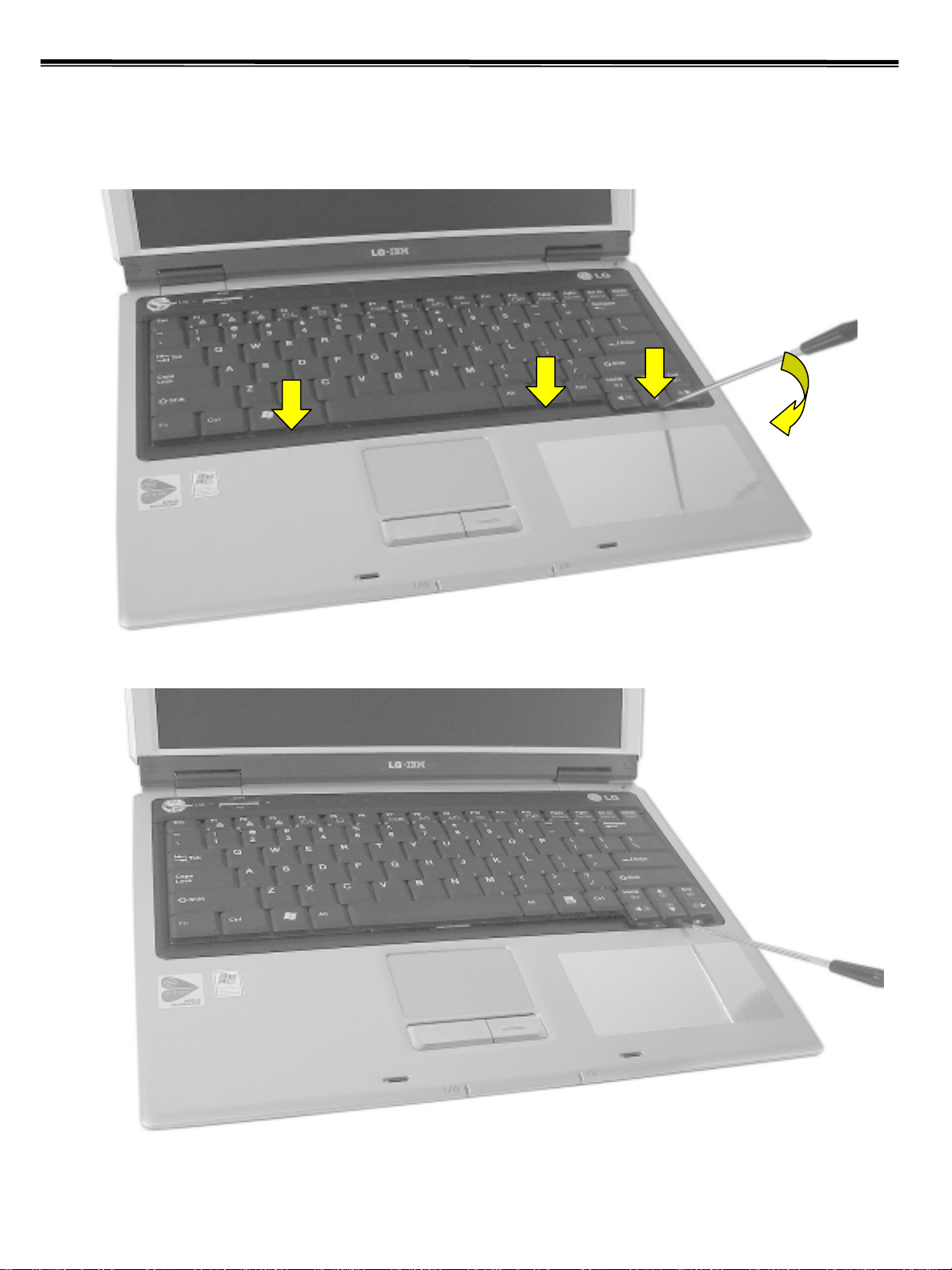
2. To remove three hooks, insert a (-) type screwdriver into a hook located at the lower end of keyboard, and pull it
up.
5
Page 6
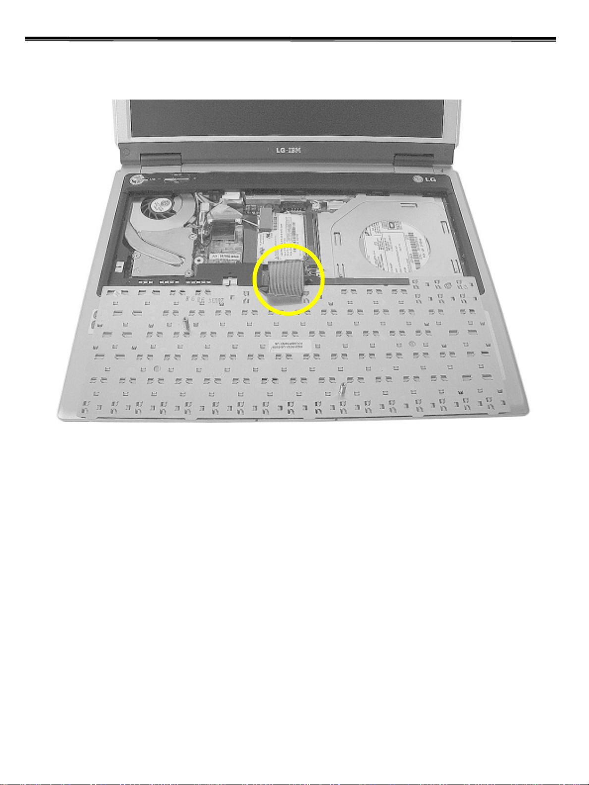
3. Disconnect the keyboard connector.
Removing and replacing a part (FRU)
1
6
Page 7
Removing and replacing a part (FRU)
Evite o uso de chaves metálicas nesta parte, por marcar
facilmente use ferramenta plástica ou somente as mãos.
1040 Retainer
Remove the following parts in order before replacing this part
Battery Pack (1010) Keyboard (1030)
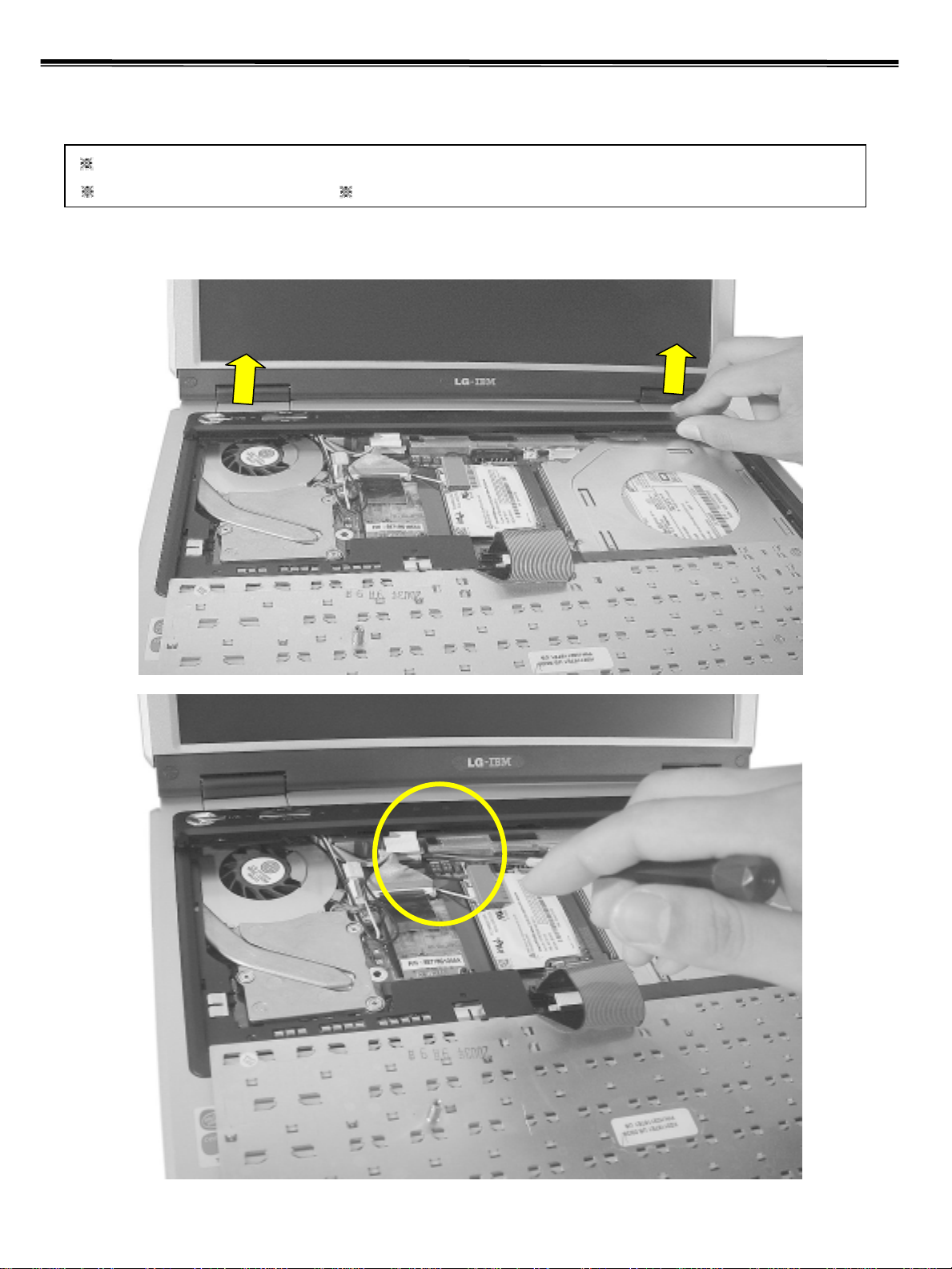
1. Pull up the retainer, and remover the connector using a (-) type screwdriver.
7
Page 8
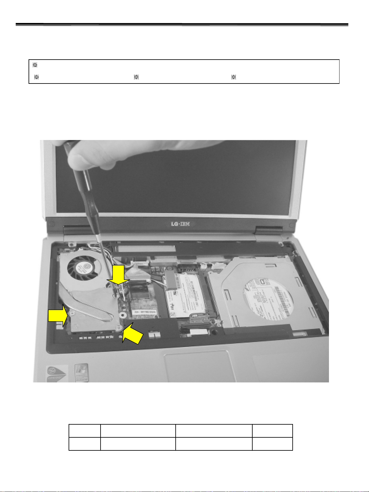
Removing and replacing a part (FRU)
1050 Fan Assembly
Remove the following parts in order before replacing this part
Battery Pack (1010) Keyboard (1030) Retainer (1040)
1. After removing a screw and the connector, pull up and remove the fan Assy using a (-) type screwdriver.
1
1
1
EASpecificationFRU No.No.
3M2.0 X L8.81SZZBZ4020A1
8
Page 9
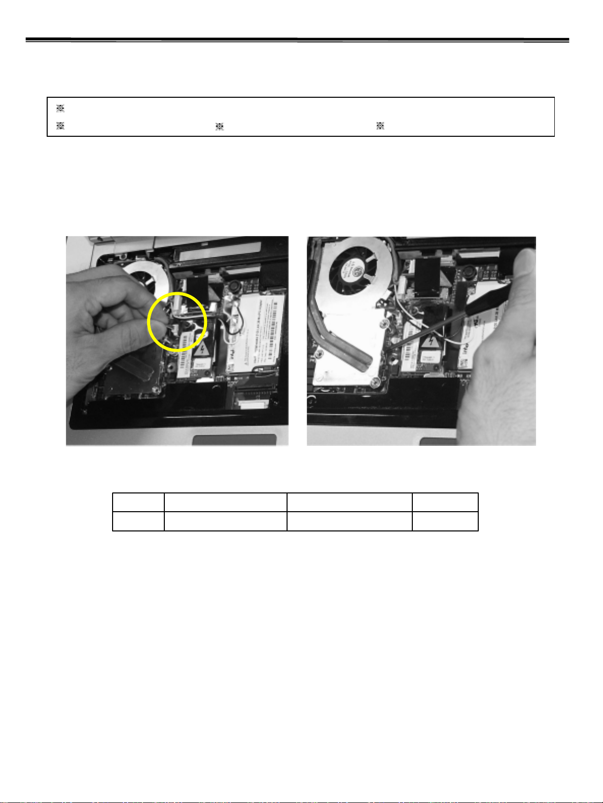
Removing and replacing a part (FRU)
1050 Fan Assembly
Remove the following parts in order before replacing this part
Battery Pack (1010) Keyboard (1030) Retainer (1040)
1. After removing a screw and the connector, pull up and remove the fan Assy using a (-) type screwdriver.
9
QtyScrewFRU No.No.
3M2.0 X L8.81SZZBZ4020A1
Page 10
Removing and replacing a part (FRU)
1060-1 Optical Disk Drive (14.1” Model)
Remove the following parts in order before replacing this part
Battery Pack (1010) Keyboard (1030) Retainer (1040)
1. Remove a screw, insert a screwdriver into the back side of ODD and push it out.
1
10
QtyScrewFRU No.No.
1M2.0 X L5.01SZZBZ4014A1
Page 11
Removing and replacing a part (FRU)
1060-2 Optical Disk Drive (15” Model)
Remove the following parts in order before replacing this part
Battery Pack (1010) Keyboard (1030) Retainer (1040)
1. Remove a screw, insert a screwdriver into the hole located at the rear of ODD and push it out.
11
QtyScrewFRU No.No.
1M2.0 X L5.01SZZBZ4014A1
Page 12

Removing and replacing a part (FRU)
1070 Wireless LAN Card
Remove the following parts in order before replacing this part
Battery Pack (1010) Keyboard (1030) Retainer (1040)
1. Remove two wireless LAN card connector, open card knob to take out the card.
12
Page 13

Removing and replacing a part (FRU)
Cuidado ao retirar a placa modem, se possível
use somente chaves plasticas ou as mãos.
1080 MDC Modem Card
Remove the following parts in order before replacing this part
Battery Pack (1010) Keyboard (1030) Retainer (1040)
1. Remove two screws and insert a screwdriver below the modem. Pull it up to disassemble.
1
1
QtyScrewFRU No.No.
2M2.0 X L3.51SZZBA4017B1
13
Page 14

1090 Display Module
Remove the following parts in order before replacing this part
Battery Pack (1010) Keyboard (1030) Retainer (1040)
Wireless LAN Card (1070)
1. Remove two screws.
Removing and replacing a part (FRU)
1
2. Remove two hinge cover screws.
1
QtyScrewFRU No.No.
2M2.5 X L8.01SZZBA4039B1
1
1
QtyScrewFRU No.No.
2M2.0 X L5.01SZZBZ4014A1
14
Page 15

Removing and replacing a part (FRU)
Nesta parte desloque o LCD para trás
levemente, com a chave de fenda plástica
aplique uma LEVE pressão, ao mesmo
3. Using a (-) type screwdriver from the back of the LCD, pull up the hinge cover with your finger. The more you
move the LCD to the back, the easier the hinge cover will pull out. Remove another hinge cover located on the
other side.
4. Remove two hinge screws.
1
1
QtyScrewFRU No.No.
2M2.5 X L8.01SZZBA4039B1
15
Page 16

Removing and replacing a part (FRU)
5. Remove the LCD connector located at the upper end of MCD modem. You will see a tag designed to make the
work easier. Pull out the tag.
6. Remove the LCD cable.
16
Page 17

Removing and replacing a part (FRU)
7. Hold the LCD with your both hands, and pull it up to remove.
See: Display Module disassembly in detail (1140)
17
Page 18

Removing and replacing a part (FRU)
Referência de parafusos.
1100 Key Deck
Remove the following parts in order before replacing this part
Battery Pack (1010) Keyboard (1030) Retainer (1040)
Fan Assembly (1050) Wireless LAN Card (1070) MDC Modem Card (1080)
Display Module (1090)
1. Remove 14 screws (for 15” model) or 11 screws (for 14.1” model). The screw type is shown on the set for
your reference.
2
3 3
1
1
1
1
Screw Specification
1
2
1
1
1
1
QtyScrewFRU No.No.
9M2.0 X L81SZZBA4083A1
2M2.0 X L151SZZBZ3010Z2
2M2.0 X L3.01SZZBA4017A3
18
Page 19

Removing and replacing a part (FRU)
2. Open the I/O port cover and remove two screws.
1
1
3. Open ODD plate and remove two screws
QtyScrewFRU No.No.
2M2.0 X L3.01SZZBA4017A1
19
QtyScrewFRU No.No.
2M2.0 X L3.01SZZBA4041A1
Page 20

Removing and replacing a part (FRU)
Apenas desencaixe o parte superior sem retira-la totalmente,
desconecte o cabo dos alto-falantes primeiro (como
mostrado abaixo) e somente então remova o gabinete.
4. Remove the cable, hold the keyboard deck with your both hands and pull it out.
20
Page 21

Removing and replacing a part (FRU)
5. Remove the speaker cable located at the front of key deck that is pulled up.
21
Page 22

Removing and replacing a part (FRU)
1110 Main Board
Remove the following parts in order before replacing this part.
Battery Pack (1010) Keyboard (1030) Retainer (1040)
Fan Assembly (1050) Wireless LAN Card (1070) MDC Modem Card (1080)
Display Module (1090) Key Deck (1100)
1. Remove two screws and disassemble the ODD Plate Assy.
1
1
1
QtyScrewFRU No.No.
3M2.0 X L3.51SZZBA4017B1
22
Page 23

Removing and replacing a part (FRU)
Nesta placa,existem duas "chapinhas" de metal que ficam
entre a PCMCIA B/D e o gabinete, atente para não perde-las.
2. Remove the PCMCIA B/D.
3. Remove the RTC battery connector from M/B.
23
Page 24

5. Remove the LAN S/B connector.
Removing and replacing a part (FRU)
24
Page 25

Removing and replacing a part (FRU)
6. Remove the power cable.
25
Page 26

7. Remove 4 M/B screws.
Removing and replacing a part (FRU)
2
1
1
1
QtyScrewFRU No.No.
3M2.0 X L5.01SZZBZ4014A1
1M2.0 X L3.51SZZBA4017B2
26
Page 27

Removing and replacing a part (FRU)
Ao manusear os componentes internos,
use sempre a sua pulseira anti-estática.
8. Hold M/B with your both hand and pull it up to remove.
27
Page 28

Removing and replacing a part (FRU)
1120 Battery Frame Assy
Remove the following parts in order before replacing this part.
Battery Pack (1010) Keyboard (1030) Retainer (1040)
Fan Assembly (1050) Wireless LAN Card (1070) MDC Modem Card (1080)
Display Module (1090) Key Deck (1100) Main Board (1110)
1. Remove a screw.
1
1
1
1
1
14.1” 15”
M2.0 X L3.51SZZBA4017B1
QtyScrewFRU No.No.
2(14.1”)
3(15.0”)
28
Page 29

Removing and replacing a part (FRU)
1130 S-Video Sub-Board
Remove the following parts in order before replacing this part.
Battery Pack (1010) Keyboard (1030) Retainer (1040)
Fan Assembly (1050) Wireless LAN Card (1070) MDC Modem Card (1080)
Display Module (1090) Key Deck (1100) Main Board (1110)
Battery Frame Assy (1120)
1. Remove the S-Video sub-board.
29
Page 30

Removing and replacing a part (FRU)
Ao remover as borrachas e o logo, tenha
cuidado para não marcar o gabinete do LCD.
1140 Display Module
Remove the following parts in order before replacing this part.
Battery Pack (1010) Keyboard (1030) Retainer (1040)
Wireless LAN Card (1070)
1. Using a knife, remove the logo and rubbers that are covering the screws. Then remove all 7 screws.
1
1
1
1
2
1
2
QtyScrewFRU No.No.
5M2.5 X L4.01SZZBA4044B1
2M2.5 X L5.01SZZBA4068A2
30
Page 31

Removing and replacing a part (FRU)
2. Disassemble the LCD front. The front hook located on the middle of LCD upper and lower end. Be careful of
the direction when removing because it is connected from inside out.
31
Page 32

Removing and replacing a part (FRU)
3. Remove cable connector. Remove the cable that is arranged around LCD from the LCD frame.
32
Page 33

Removing and replacing a part (FRU)
4. Remove 9 screws (for 15” model) or 8 screws (for 14.1”)
1
22
3
1
1
1
3
22
33
QtyScrewFRU No.No.
4M2.0 X L2.51SZZBZ3009B1
4M2.5 X L5.01SZZBA4068A2
2M2.0 X L4.51SZZBA4082A3
Page 34

Removing and replacing a part (FRU)
5. Press the hook on the both side of LCD with a (-) type screwdriver and remove from the LCD rear panel.
34
Page 35

Removing and replacing a part (FRU)
6. Remove LCD from the LCD rear panel.
35
 Loading...