

LG LS43ST User Manual
LENNOX HEARTH PRODUCTS
INSTALLATION
INSTRUCTIONS
MAGNA-FIRE
43" Wood Burning Fireplace
P/N 850,004M REV. F 10/2006
MODELS
LS43ST
This installation manual will enable you to obtain a safe, efficient and
dependable installation of your fireplace system. Please read and
understand these instructions before beginning your installation.
Do not alter or modify the fireplace or its components under any
circumstances. Any modification or alteration of the fireplace system,
including but not limited to the fireplace, chimney components and
accessories, may void the warranty, listings and approvals of this system
and could result in an unsafe and potentially dangerous installation.
RETAIN THESE INSTRUCTIONS
FOR FUTURE REFERENCE
IMPORTANT! TO ASSURE PROPER ALIGNMENT OF GLASS DOORS:
INSTALL THIS FIREPLACE IN A SQUARE AND PLUMB CONDITION,
USING SHIMS AS NECESSARY AT SIDES AND/OR BOTTOM.
OTL Report No. 116-F-19-02
NOTE: DIAGRAMS & ILLUSTRATIONS NOT TO SCALE.
1

TABLE OF CONTENTS
Safety Rules .................................... page 2
Tools and Building Supplies ............ page 2
Precautions ..................................... page 3
Introduction ..................................... page 3
Clearances/Height Requirements..... page 3
Chimney System ............................. page 4
Assembly Outline............................. page 4
Location of Fireplace ....................... page 4
Assembly Steps ............................... page 5
Preinstallation Notes........................ page 5
Clearances ....................................... page 5
Installing the Fireplace ..................... page 5
Framing Wall Variations .................. page 6
Framing Specifications.................... page 7
Fireplace Specifications .................. page 8
Installing the Chimney System ........ page 9
Ten Foot Rule Summary .................. page 12
Multiple Terminations ...................... page 12
Chimney Component Calculations ... page 12
Special Offset Instructions............... page 12
Vertical Elevation Chart ................... page 13
Offset Elevation Chart ..................... page 14
Offset Calculations........................... page 15
Installing Offsets.............................. page 15
30° Offset through Floor/Ceiling ...... page 16
Glass Doors ..................................... page 16
Optional Equipment Considerations. page 16
Combustion Air Kits ........................ page 16
Gas Line Connection........................ page 17
Cold Climate Insulation.................... page 17
Fireplace Finishes ............................ page 17
Mantels and Trim............................. page 17
Hearth Extensions............................ page 17
Finish Requirements ........................ page 19
Installation Components .................. page 19
IMPORTANT: PLEASE READ AND
UNDERSTAND THESE RULES TO
FOLLOW FOR SAFETY.
1. Before starting your fireplace installation,
read these installation instructions carefully to
be sure you understand them completely and in
entirety. Failure to follow them could cause a
fireplace malfunction resulting in serious injury
and/or property damage.
2. Always check your local building codes. The
installation must comply with all local, regional,
state and national codes and regulations.
3. These fireplaces must be installed with
Security Chimneys FTF13 (12 ¹⁄₂" inside diameter) Chimney System only. These systems
are intended for use in any application where
a traditional masonry type fireplace would
apply. The chimney system must always vent
to the outside of the building.
4. To ensure a safe fireplace system and to
prevent the build-up of soot and creosote,
inspect and clean the fireplace and chimney
prior to use and periodically during the heating
season.
5. Use solid fuel only. DO NOT use artificial
wax based logs, chemical chimney cleaners or
flame colorants in your fireplace.
6. DO NOT use charcoal or coal under any
circumstances.
7. NEVER use gasoline, gasoline-type lantern
fuel, kerosene, charcoal lighter fluid, or similar
liquids to start or “freshen up” a fire in this
fireplace. Keep any flammable liquids a safe
distance from the fireplace.
8. NEVER leave children unattended when
there is a fire burning in the fireplace.
9. Always keep flue damper open when heat is
present in the fireplace.
10. Before servicing, allow the fireplace to
cool. Always shut off any electricity or gas to
the fireplace while working on it. This will
prevent any possible electrical shock or burns.
11. This fireplace is not intended to heat an
entire home or be used as a primary heat
source. It is designed to ensure homeowner
comfort by providing supplemental heat to the
room.
12. Always ensure an that adequate supply of
replacement combustion air from the outside
of the house is accessible to the fire to support
normal combustion. Fireplaces consume large
volumes of air during the normal combustion
process. In the event the home is tightly sealed
with modern energy efficient features, the optional combustion air kit may not provide all
the air required to support combustion.
The manufacturer is not responsible for any
smoking or related problems that may result
from the lack of adequate combustion air. It is
the responsibility of the builder/contractor to
ensure that adequate combustion air has been
provided for the fireplace.
13. DO NOT use a fireplace insert or any other
products not specified herein by the manufacturer
for use with this fireplace. All gas log sets must be
operated with the damper clamped open.
14. "Smoke free” operation is not warranteed
nor are we responsible for inadequate system
draft caused by mechanical systems, general
construction conditions, inadequate chimney
heights, adverse wind conditions and/or unusual environmental factors or conditions beyond our control.
15. Never, under any circumstances, install a
fireplace, chimney component or any accessories, that has visible or suspected physical
damage as a result of handling or transportation. These items should be inspected by your
distributor or qualified factory representative
to ensure safe condition. When in doubt, consult your distributor.
16. For additional safety considerations and
complete operating instructions, refer to the
Care and Operation Manual provided with the
fireplace.
TOOLS AND BUILDING SUPPLIES
NORMALLY REQUIRED
Tools should Include:
Phillips screwdriver
Hammer
Saw and/or sabersaw
Level
Measuring tape
Plumb line
Electric drill and bits
Pliers
Square
Building supplies:
Framing materials
Wall finishing materials
Caulking materials (noncombustible)
Fireplace surround and hearth
extension materials (noncombustible)
2
NOTE: DIAGRAMS & ILLUSTRATIONS NOT TO SCALE.
PRECAUTIONS
Note: These fireplace systems are not difficult
to install. However, in the interest of safety, it is
recommended that the installer be a qualified or
certified “tradesman” familiar with commonly
accepted fireplace installation and safety techniques as well as prevailing local codes.
The most important areas of concern dealing
with the installation of factory-built fireplaces are
clearances to combustible materials, proper assembly of component parts, height of the chimney system, the proper use of accessories supplied by the manufacturer and the techniques
employed in using finishing materials applied to
the wall surrounding the fireplace, hearth extensions and wall shields. Each of these topics will
be covered in thorough detail throughout this
manual. Please give each your special attention
as you progress with your installation.
TYPICAL INSTALLATION
INTRODUCTION
General Information
This Signature Series LS43ST is a radiantheat, two-sided fireplace with a variety of
glass door options. A steel grate is also included with the LS43ST to properly position
the fire. An outside combustion air kit is
available as optional equipment.
Note: Illustrations shown reflect “typical” installations with nominal dimensions and are for
design and framing reference only. Actual installations may vary due to individual design preferences. However, always maintain minimum clearances to combustible materials and do not violate any specific installation requirements.
These fireplaces have been tested and listed
by Omni-Test Laboratories (Report No. 116F-19-02) to U.L. standard 127. These units
are intended for installation in residential
homes and other buildings of conventional
construction including commercial, not in
mobile homes.
These fireplace systems are designed for installation in accordance with the National Fire
Protection Standard for chimneys, fireplaces
and solid fuel burning appliances; NFPA 211
and in accordance with codes such as the BOCA
Basic/National Codes, the Standard Mechanical Code and the Uniform Building Codes.
CLEARANCES AND HEIGHT
REQUIREMENTS
The fireplace may be placed on or near normal
construction materials*. The combustion air
kit, firestop spacer and roof flashing (not chase
flashings) may be placed directly on or against
normal construction materials.* The chimney
and fireplace outer wrapper require a minimum 2" and 1" air space to combustibles
respectively. A combustible mantle may be
installed 12" above the opening of the fireplace
as per NFPA 211, Section 7-2.3.3.
The fireplace opening of the LS43ST must be
kept a minimum of 12" (305 mm) from a side
wall. A perpendicular side wall can not be
closer that 12" (305 mm) to the LS43ST
fireplace.
As with all chimney installations, avoid overhead obstructions such as trees, power lines,
etc. Additionally chimney terminations must
meet certain clearance to roof requirements
detailed in the paragraph titled Ten-Foot Rule
Summary.
The fireplace and chimney system must be
enclosed when installed in or passing through
a living area where combustibles or people
may come in contact with it. This is important
to prevent possible personal injury or fire
hazard.
Model LS43ST
Figure 1
Chimney and
Termination
The local authority having jurisdiction should
be consulted before installation, to determine if
any permits need to be obtained.
WARNING: FAILURE TO USE MANUFACTURE PROVIDED PARTS, VARIATIONS IN
TECHNIQUES AND CONSTRUCTION MATERIALS OR PRACTICES OTHER THAN
THOSE DESCRIBED IN THIS MANUAL
MAY CREATE A FIRE HAZARD AND VOID
THE LIMITED WARRANTY.
The LS43ST system consists of three “subsystems”:
1. The Fireplace and Door Assemblies
2. The Chimney and Termination
3. The Optional Combustion Air Kit
For questions, please call your distributor or
the manufacturer. Special restrictions apply to
the front and facing of the fireplace and nearby
walls (See pages 18, 19 and 20 ).
*Construction Materials:
• framing materials • paneling
• particle board • flooring
• dry wall • etc.
• plywood
NOTE: DIAGRAMS & ILLUSTRATIONS NOT TO SCALE.
3
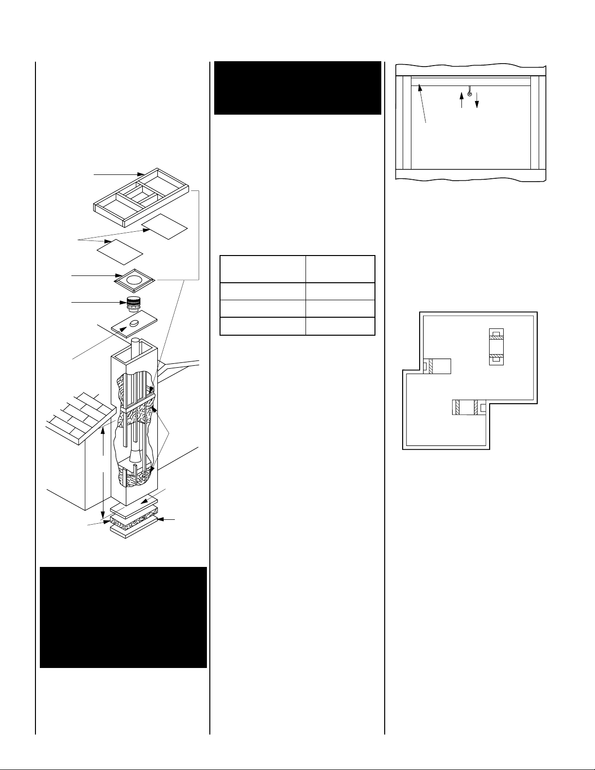
CHIMNEY SYSTEM
Damper
Closed
Damper
Open
Lintel
These fireplaces are designed and code listed
for use with Security Chimneys FTF13 chimney
System only. Always use Security Chimneys
FTF13 chimney components with these fireplaces. Do not modify or alter these components as this may cause a potential serious
hazard and void the Warranty.
Insulate Joists
Same As Ceiling
Draft Stops
Firestop
FTF13
CTDT
Termination
Note: NonCombustible
Chase
Flashing
Must Be
Used To
Cover
Chase
Opening
Optional
Insulation
In Outside
Walls Of
Chase
8'
Level
Solid
Continuous
Surface
Outside
Insulation
(Thermal Barrier)
Base
Figure 2
WARNING: IF INSULATION IS USED, THE
FIREPLACE MUST NOT BE PLACED DIRECTLY AGAINST IT. INSULATION OR
VAPOR BARRIERS, IF USED, MUST FIRST
BE COVERED WITH GYPSUM BOARD,
PLYWOOD, PARTICLE BOARD OR OTHER
MATERIAL TO ASSURE INSULATION AND
VAPOR BARRIERS REMAIN IN PLACE.
WARNING: DO NOT PACK OR FILL REQUIRED AIR SPACES WITH INSULATION
OR OTHER MATERIAL. NO MATERIAL IS
ALLOWED IN THESE AREAS.
Note: Do not insulate the chase cavity with
blown or fill type insulation materials.
Chimney Height
The total height of your LS43ST fireplace
system from the surface the fireplace rests
on to the chimney top must not exceed 80'
(24.4m) and must also meet minimum system height chart.
Minimum System Height
Model LS43ST Security's
FTF13
Vertical Installation 14' 0" (3.7 m)
One Offset 15 ¹⁄₂ 0" (3.9 m)
Two Offsets 22' 0" (5.6 m)
Chase Enclosure
A chase is a vertical box-like structure constructed to surround the fireplace and chimney. Refer to
Figure 2
for a typical chase
configuration. A chase should be constructed
and insulated just like any outside wall. Chase
insulation in a cold climate installation is not
required for safety.
ASSEMBLY OUTLINE
Before You Start
Check your inventory list to be sure you have all
the necessary parts supplied in good usable
condition. Check also for any concealed damage.
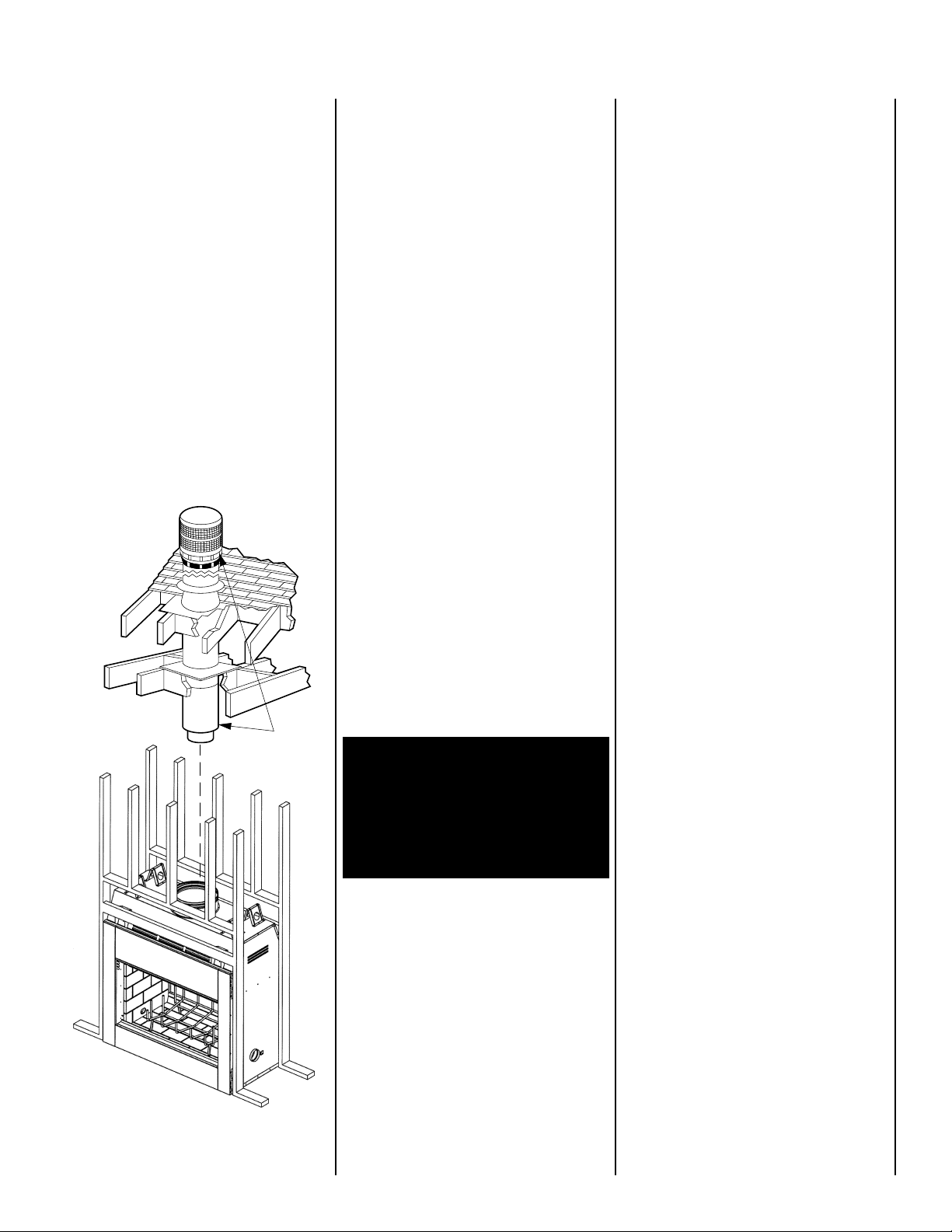
Check the operation of the damper. The damper
is controlled through the use of a control lever
located within the firebox opening at the top
center just behind the firebox lintel (
The control lever snaps into place at the extreme range of motion, up and back in the
closed position. When pulled forward and
down, the damper is open.
Figure 3
).
Figure 3
LOCATION OF FIREPLACE
Carefully select the proper location for heat
circulation, aesthetics, chimney obstructions
and clearance to side wall(s). With proper preplanning, a slight adjustment of a few inches
can save considerable time and expense later
during construction and assembly.
Figure 4
Carefully consider the position of the fireplace
opening with respect to the location of adjacent or nearby stairwells, bath or kitchen exhaust fans and/or return air registers for forced
air furnaces/air conditioners that could cause
a smoking fireplace condition if the house is
tightly insulated.
This system is intended to be installed in residential homes and buildings of conventional
construction, not in mobile homes.
4
NOTE: DIAGRAMS & ILLUSTRATIONS NOT TO SCALE.
When locating the fireplace, consideration must
Hearth
Extension
Floor
Hearth
Extension
Metal Safety
Strips
Platform
be given to combustibles and final finishing.
For an example of this, see
Figure 5
and
confine the final location of combustible finish
materials to the "Safe Zone".
DO NOT permanently place furniture or other
items such as decorative pillows within 60" of
the fireplace front face.
Black Portion Of Frame
Not To Be Covered With
Combustible Materials
Wall
7”
30°
4”
Door
Opening
12”
Min.
Covering
Safe
Zone
Figure 5
ASSEMBLY STEPS
Note: The following steps represent the normal
sequence of installation. Each installation is
unique, however, and might require a different
sequence.
1. Position firebox prior to framing or into
prepared framing.
2. Install the chimney system.
3. Install optional outside combustion air kit.
4. Plumb gas line if a decorative gas appliance
will be used. (Gas connections should only be
performed by an experienced, licensed/certified tradesman).
PRE-INSTALLATION NOTES
The fireplace may be installed directly on a
combustible floor or raised on a platform of an
appropriate height. Do not place fireplace on
carpeting, vinyl or other soft floor coverings. It
may, however, be placed on flat wood, plywood, particle board or other hard surfaces.
Be sure fireplace rests on a solid continuous
floor or platform with appropriate framing for
support and so that no cold air can enter the
room from under the fireplace.
The fireplace may be positioned and then the
framing built around it, or the framing may be
constructed and the fireplace positioned into
the opening.
Usually, no special floor support is needed for
the fireplace, however, to be certain:
1. Estimate the total weight of the fireplace
system including chimney and surround materials such as brick, stone, etc., to be installed. Shipping weights for the fireplace may
be found on page 20.
2. Measure the square footage of the floor
space to be occupied by the system, surrounds
and hearth extensions.
3. Note the floor construction, i.e. 2 x 6’s, 2 x 8’s
or 2 x 10’s, single or double joists, type and
thickness of floor boards.
4. Use this information and consult your local
building code to determine if you need additional support.
If you plan to raise the fireplace and hearth
extension, build the platform assembly then
position fireplace and hearth extension on top.
Secure the platform to the floor to prevent
possible shifting.
INSTALLING THE FIREPLACE
Step 1. Slide the fireplace into prepared fram-
ing or position fireplace in its final position and
frame later.
The fireplace may not be recessed into a combustible floor. Maintain the floor to hearth clearance established by the fireplace lower front
face.
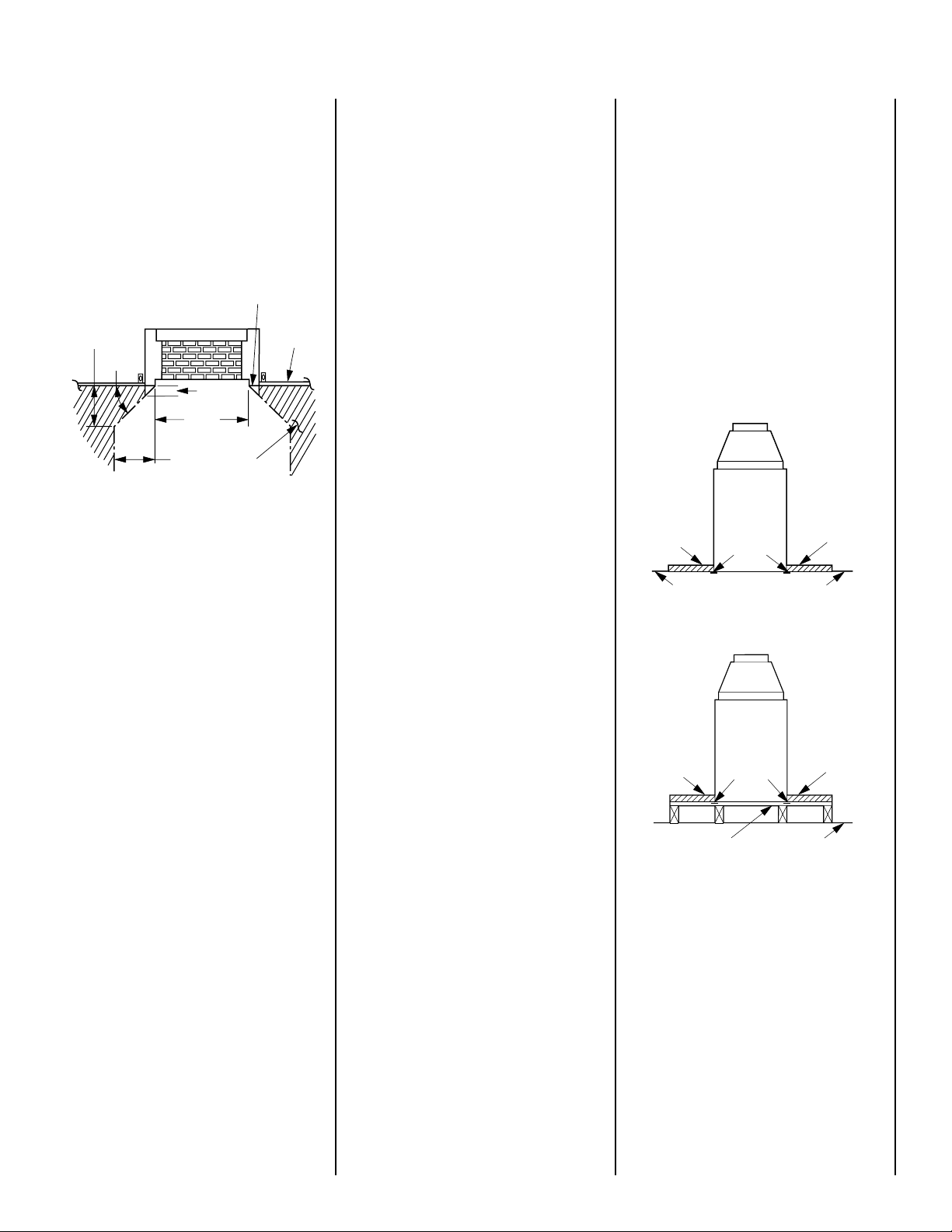
Step 2. Insert the provided metal safety strips,
beneath the fireplace as illustrated (
and 8
). The safety strips should overlap ¹⁄₂" for
continual coverage of the floor.
Note: Safety strips are not required when fireplace rests on a noncombustible surface.
Hearth
Extension
Floor
Metal Safety
Strips
Figure 6
Figures 6, 7
Hearth
Extension
Floor
6. Install both door assemblies.
7. Complete finish wall material, surround and
hearth extension to your individual taste.
Study the three dimensional illustration (
ure 1
) to get a general idea of each element of
your fireplace system.
Fig-
CLEARANCES
Minimum clearance to combustibles for the
appliance is as follows: sides - 1" (25 mm),
floor - 0" (0 mm), adjacent wall - 12" (305 mm),
ceiling - 37 ¹⁄₂" (953 mm).
NOTE: DIAGRAMS & ILLUSTRATIONS NOT TO SCALE.
Figure 7
Note: Install the hearth extension only as illus-
trated.
5
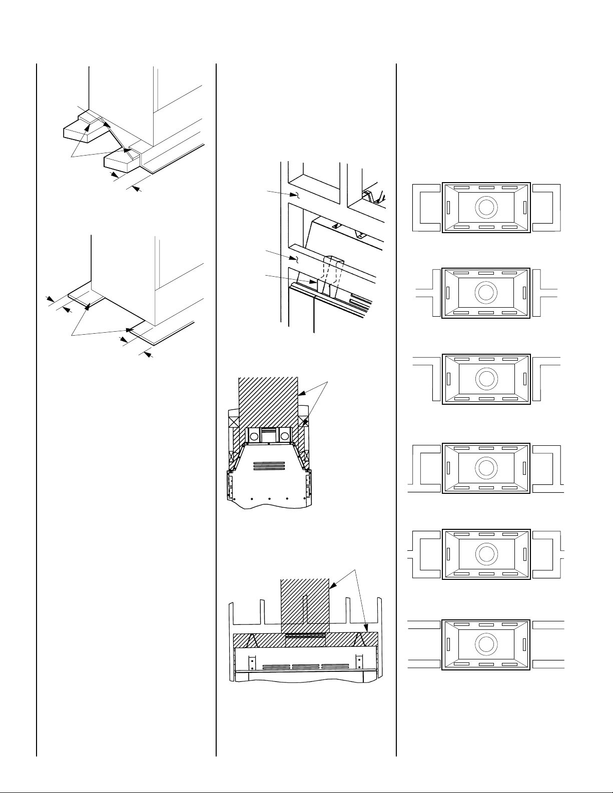
Platform
Metal
Safety Strips
IMPORTANT: UNDER NO CIRCUMSTANCES
CAN THE FIREPLACE TOP SPACERS (
10
) BE REMOVED OR MODIFIED, NOR MAY
FIGURE
YOU NOTCH THE HEADER TO FIT AROUND
OR BE INSTALLED LOWER THAN THE SPACERS. THE HEADER MAY BE IN DIRECT CONTACT WITH THE TOP SPACERS BUT MAY NOT
BE SUPPORTED BY THEM.
FRAMING WALL VARIATIONS
As many as six (6) different framed wall configurations can be constructed to enclose the
LS43ST fireplace. The following illustrations
depict these variations of wall enclosures. Several of these designs may incorporate book
shelves, wood storage boxes, etc.
LS43ST - Wall Types
2" Min.
(51 mm)
Figure 8
*
Metal
Safety Strips
*
*
2" Min.
(51 mm)
Figure 9
The safety strips should extend in front and
sides of the fireplace opening 2" (51 mm) . In
the event a wooden support is used to elevate
the fireplace above the floor, a “Z” type safety
strip should be fabricated and used to protect
the front surface of the wood support as well
as the floor beneath the hearth extension (
Figures 8 and 9
). The safety strips should be
see
tacked down to prevent possible movement.
Note: The “Z” type safety strip is not supplied.
4 x 6 Header
2 x 4 False
Header
Spacer
Figure 10
No Combustible
Materials in
Shaded Areas
Note: A minimum 2”
air space clearance
to combustibles and
any portion of the
chimney is required.
“C” Type Wall
“T” Type Wall
“L” Type Wall
“H” Type Wall
Step 3. Refer to fireplace drawings and speci-
fications on pages 7 and 8 for framing dimensions and details. False header may be positioned directly on top of the fireplace spacers
(
see Figures 10, 11 and 12
).
6
Figure 11
Figure 12
NOTE: DIAGRAMS & ILLUSTRATIONS NOT TO SCALE.
No Combustible
Materials in
Shaded Areas
“Y” Type Wall
Parallel Wall
Figure 13
 Loading...