

Page 1

ENGLISH
LG
Room Air Conditioner
INSTALLATION MANUAL
LG
http://www.lgservice.com
IMPORTANT
• Please read this instruction manual completely before
installing the product.
• When the power cord is damaged, replacement should be
performed by authorized personnel only.
• Installation work must be performed in accordance with
the national wiring standards by authorized personnel
only.
• Please retain this installation manual for future reference
after reading it thoroughly.
FRANÇAIS ESPAÑOL
Page 2

2 Room Air Conditioner
Room Air Conditioner Installation Manual
TABLE OF CONTENTS
Safety Precautions .........................3
Introduction .....................................9
Symbols Ued in This Manual ......9
Features .......................................9
Installation .....................................10
Installation Parts ........................10
Installation Tools ........................10
Installation Map..........................11
Confirm The Refrigerant ...........12
Select The Best Location .........13
Piping Length And Elevation.....14
How To Mount Installation Plate
..15
Drill a Hole In The Wall..............15
Flaring Work...............................16
Connecting The Piping..............17
Connection Of The Drain Hose
...22
Connection Of Piping -Outdoor
...22
Connection Of The Cable .........23
Checking The Drainage ............25
Forming The Piping ...................26
Air Purging .................................27
Air Purging With Vacuum Pump
..27
Charging.....................................29
Tes t R unn ing .................................30
❏ Installation plate
❏ Four type "A" screws
❏ Connecting cable
❏ Pipes: Suction line
Evaporator line
(Refer to page 13)
❏ Insulation materials
❏ Additional drain pipe
(
Outer Diameter
.........
15.5mm(0.61in))
❏ Two type "B" screws
Installation
Requirements
Required Parts Required Tools
❏ Level gauge
❏ Screwdriver
❏ Electric drill
❏ Hole core drill(ø70mm(2.76in))
❏ Flaring tool set
❏ Specified torque wrenches
4.2kg.m, 6.6kg.m
(different depending on model No.)
(Refer to page 17)
❏ Spanner .....................Half union
❏ Aglassofwater
❏ Screw driver
❏ Hexagonal
wrench(4mm(0.16in))
❏ Gas Leak Detector
❏ Vacuum pump
❏ Manifold Gauge
❏ Owner's manual
❏ Thermometer
❏ Remote Control Holder
Page 3
Installation Manual 3
ENGLISH
Safety Precautions
To prevent the injury of the user or other people and property damage, the following instructions
must be followed.
■ Incorrect operation due to ignoring instruction will cause harm or damage. The seriousness is
classified by the following indications.
■ The meanings of the symbols used in this manual are as shown below.
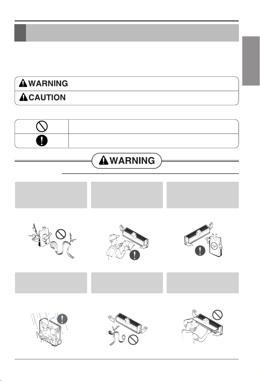
This symbol indicates the possibility of death or serious injury.
This symbol indicates the possibility of injury or damage to properties only.
■ Installation
Be sure not to do.
Be sure to follow the instruction.
Safety Precautions
Do not use damaged power
cords, plugs, or a loose socket.
• There is risk of fire or electric shock.
For electrical work, contact the
dealer, seller, a qualified
electrician, or an Authorized
Service Center.
• There is risk of fire or electric shock.
Always use the power plug and
socket with the ground terminal.
• There is risk of electric shock.
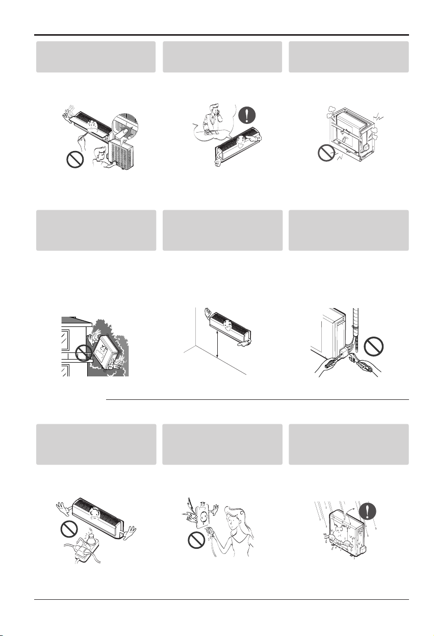
Install the panel and the cover of
control box securely.
• There is risk of fire or electric shock.
Do not modify or extend the
power cord.
• There is risk of fire or electric shock.
Do not install, remove, or reinstall the unit by yourself
(customer).
• There is risk of fire, electric shock,
explosion or injury.
Page 4
4 Room Air Conditioner
Safety Precautions
■ Operation
Be cautious when unpacking and
installing the product.
• Shape edges could cause injury. Be
especially careful of the sharp edges.
For installation, always contact
thedealeroranAuthorized
Service Center.
• There is risk of fire, electric shock,
explosion, or injury.
Do not install the product on a
defective installation stand.
• It may cause injury, accident, or
damage to the product.
Be sure the installation area
does not deteriorate with age.
• If the base collapses, the air
conditioner could fall with it, causing
property damage, product failure, and
personal injury.
Install the indoor unit on the wall
where the height from the floors
more then 8ft(2.4m)
• There are sharp moving parts that
could cause personal injury.
Do not handle the pipe by
yourself(customer)
• High-Pressure refrigent may cause
personal injury.
Use a dedicated outlet for this
appliance.
• There is risk of fire or electric shock.
Grasp the plug to remove the
cord from the outlet. Do not
touch it with wet hands.
• There is risk of fire or electric shock.
Do not allow water to run into
electric part.
• There is risk of fire, failure of the
product, and/or electric shock.
8ft(2.4m)
Page 5

Installation Manual 5
ENGLISH
Safety Precautions
Do not place a heater or other
appliances near the power cable.
•
There is risk of fire, failure of the product,
and/or electric shock.
Do not let the air conditioner run
for a long time when the
humidity is very high and a door
or a window is left open.
• Moisture may condense and wet or
damage furnishings.
Do not store of use flammable
gas or combustibles near the air
conditioner.
• There is risk of fire or product failure.
Do not use the product in a
tightly closed space for a long
time.
• Oxygen deficiency could occur.
• Some ventilation by opeing window
is necessary for the fresh air.
When flammable gas leaks, turn off
the gas and open a window for
ventilation before turning the product
on. Do not use the telephone or turn
switches on or off.
• There is risk of explosion or fire.
Unplug the unit if strange
sounds odors or smoke comes
from it.
•
There is risk of fireproduct failure and/or
electric shock.
Stop operation and close any
window in storm or hurricane.
before the hurricane arrives.
• There is risk of property damage,
failure of product, or electric shock.
Do not open the inlet grill of the
product during operation. (Do
not touch the electrostatic filter,
if the unit is so equipped.)
• There is risk of physical injury, electric
shock, or product.
When the product is soaked
(flooded or submerged), contact
an Authorized Service Center.
• There is risk of electrical shock.
Thinner
Wax
Page 6
6 Room Air Conditioner
Safety Precautions
■ Installation
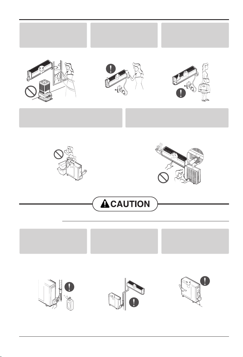
Always check for gas(refrigerant)
leakage after installation or
repair of product.
• Low refrigerant levels may cause
product failure.
Install the drain hose to ensure
that water is drained away
properly.
• A bad connection may cause water
leakage.
Keep level even when installing
the product.
• To avoid vibration or water leakage.
Take care to ensure that nobody could step on or
fall onto the outdoor unit.
• There could result in personal injury and product damage.
Do not insert hands or other objects through the air
inlet or outlet while the air conditioner is plugged
in.
• There are sharp and moving parts that could cause
personal injury.
Ventilate the product from time to
time when operating it together
with a stove, etc.
• There is risk of fire or electrical shock.
Unplug the appliance before
performing cleaning or
maintenance.
• Thereisriskofelectricshock.
When the product is not be used
for a long time disconnect the
power supply plug or turn off the
breaker.
• There is risk of product damage or
failure, or unintended operation.
90˚
Page 7
Safety Precautions
Installation Manual 7
ENGLISH
■ Operation
Do not install the product where
the noise or hot air from the
outdoor unit could damage the
neighborhoods.
• It may cause a problem for your
neighbors.
Use two or more people to lift
and transport the air conditioner
• Avoid personal injury.
Do not install the product where
it will be exposed to sea wind
(salt spray) directly.
• It may cause corrosion in the product.
Corrosion, particularly on the
condenser and evaporator fins, could
cause product malfunction or
inefficient operation.
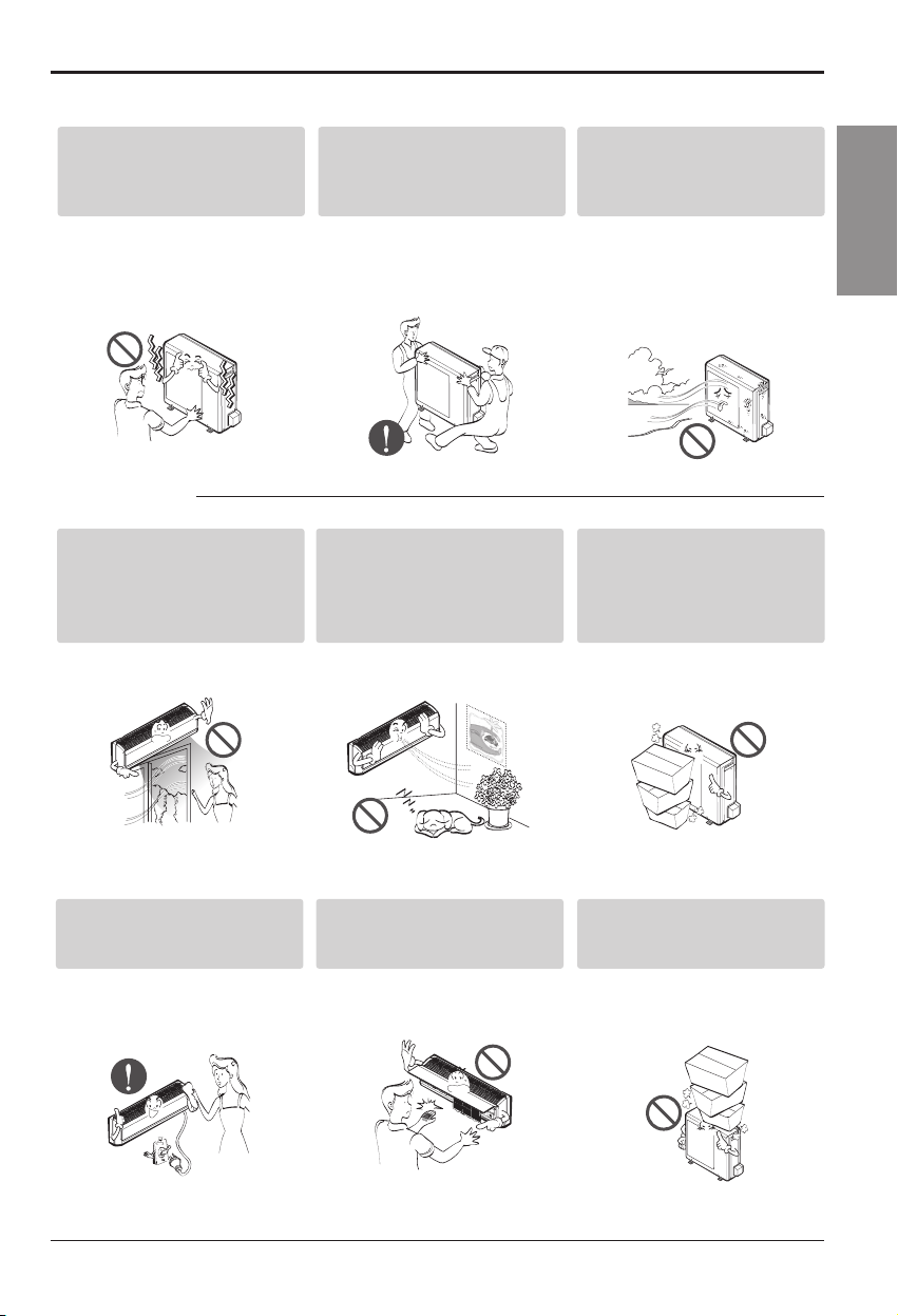
Do not direct airflow at room
occupants.
• This could damage your health.
Do not use the product for special
purposes, such as preserving
foods, works of art, etc. It is a
consumer air conditioner, not a
precision refrigeration system.
• There is risk of damage or loss of
property.
Do not block the inlet or outlet of
air flow.
• It may cause product failure.
Use a soft cloth to clean.
Do not use harsh detergents,
solvents, etc.
• There is risk of fire, electric shock
or damage to the plastic parts of the
product.
Do not touch the metal parts of
the product when removing the
air filter. They are very sharp!
• There is risk of personal injury.
Do not step on or put anything
on the product. (outdoor unit)
• There is risk of personal injury and
failure of product.
Page 8
8 Room Air Conditioner
Safety Precautions
■ Disuse
Always insert the filter securely. Clean the filter
every two weeks or more often if necessary.
• A dirty filter reduces the efficiency of the air conditioner and
could cause product malfunction or damage.
Do not drink the water drained from the unit.
• It is not sanitary and could cause serious health issues.
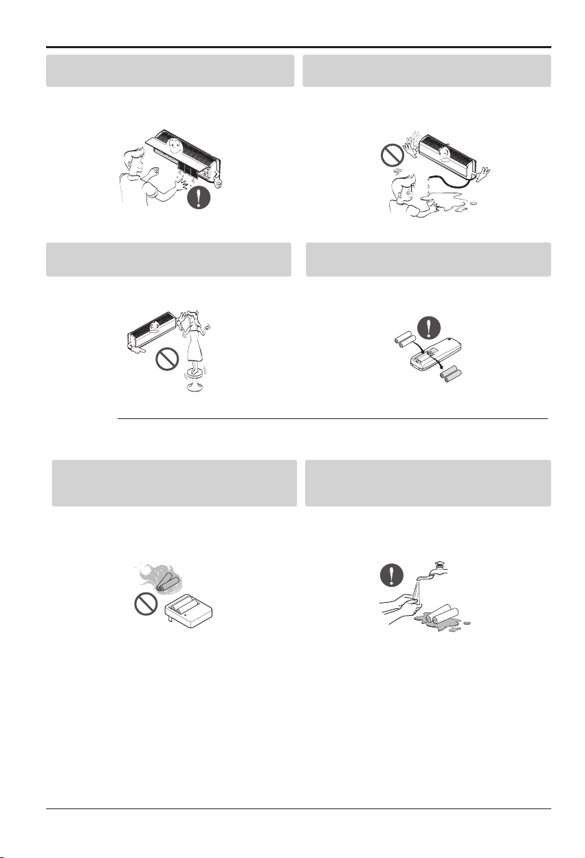
Do not recharge or disassemble the batteries. Do
not dispose of batteries in a fire.
• They may burn or explode.
If the liquid from the batteries gets onto your skin
or clothes, wash it well with clean water. Do not
use the remote if the batteries have leaked.
• The chemicals in batteries could cause burns or other
health hazards.
Use a firm stool or ladder when cleaning or
maintaining the air conditioner.
• Be careful and avoid personal injury.
Replace all the batteries in the remote.
• There is risk of fire or explosion.
Page 9

Installation Manual 9
ENGLISH
Introduction
This symbol alerts you to the risk of electric shock.
This symbol alerts you to hazards that may cause harm to
the air conditioner.
This symbol indicates special notes.
NOTICE
Introduction
Symbols Used In This Manual
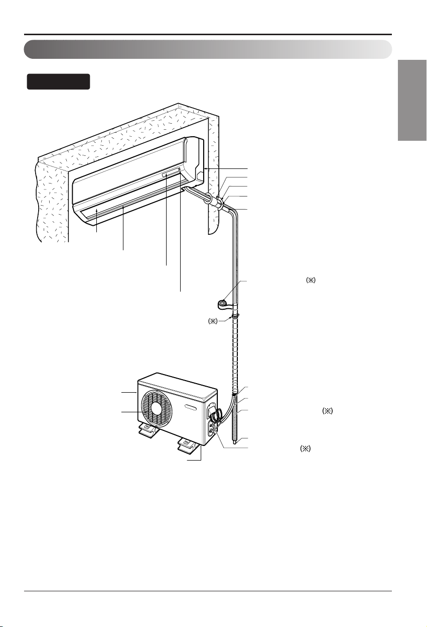
Features
Air Intake Vents
Air Outlet Vents
Connecting
Wires
Piping
Drain Hose
Base Plate
Air Outlet
Vents
Air Intake
Vents
Piping
Connecting
Wires
Drain Hose
Signal Receptor
Base Plate
Front Panel
Air Inlet
Air Filter
Page 10

10 Room Air Conditioner
Installation
Type "A" screw and plastic anchor
Type "B" screw
Remote Control Holder
Installation plate
Figure FigureName
Screw driver
Electric Drill
Measuring Tape, Knife
Hole Core Drill
Spanner
Torque wrench
Ohmmeter
Hexagonal wrench
Ammeter
Gas Leak Detector
Thermometer,
Level
Flaring Tool Set
Name
Installation Parts
Installation Tools
Installation
Read carefully, and then follow step by step.
Page 11
Installation Manual 11
ENGLISH
Installation
Installation Map
Installation parts you should purchase.
Vertical Air deflector
Air Discarge
Forced Operation Button
Operation Indication Lamps/
Signal Receptor
Vinyl tape(Wide)
• Apply after carrying out a
drainage test.
• To carry out the drainage
test, remove the air filters
and pour water into the heat
exchanger.
Saddle
Gas side piping
Liquid side piping
Additional drain pipe
Drain Hose
Base Plate
Air Inlet Vents
Connecting cable
Installation Plate
Sleeve
Bushing-Sleeve
Putty(Gum Type Sealer)
Bend the pipe as closely
on the wall as possible,
but be careful that it
doesn't break.
NOTICE
NOTE: refrigerant line wall thickness must be at least 0.8 mm (0.031 inch)
Air Outlet Vents
Page 12

Installation
1. Check the quality label on the indoor and outdoor unit.
2. Make certain that the refrigerant is R-410A.
THIS PRODUCT CONTAINS R-410A REFRIGERANT
1) Different compressor oil
- R-410A(Polyol ester) / R-22(Mineral).
- Do not mix the existing mineral oil.
- Do not apply used pipe, tools and gauges covered with the existing mineral oil.
2) Absorption of moisture
-Compressor’s oil has the high absorption rate of moisture.
3) Composition
- R-410A(R32:R125=50:50wt%).
NOTE: Never mix with other refrigerants
4) High pressure.
- 1.6 times higher than R-22.
- High Pressure refrigerant may cause personal injury.
Do not handle the pipe by yourself (customer) High-pressure refrigerant may cause personal injury.
- manifold gauge ,charging and any piping tools must be dedicated to R-410A systems.
NOTICE
Confirm The Refrigerant
12 Room Air Conditioner
Boiling Pt.(
°C) Vapor pressure(25°C)(kg f/cnf) Vapor density(25°C)(kg/m2)
R-410A -51.4 15.9 64
R-22 -40.8 9.6 44.4
Example : Split type 12,000 Btu/h
120
100
100
80
93
89
84
76
60
40
20
0
R-410A
R-22
100%
70% 50% 30%
0%
100%70%50%30%0%
Page 13
Installation Manual 13
ENGLISH
Installation
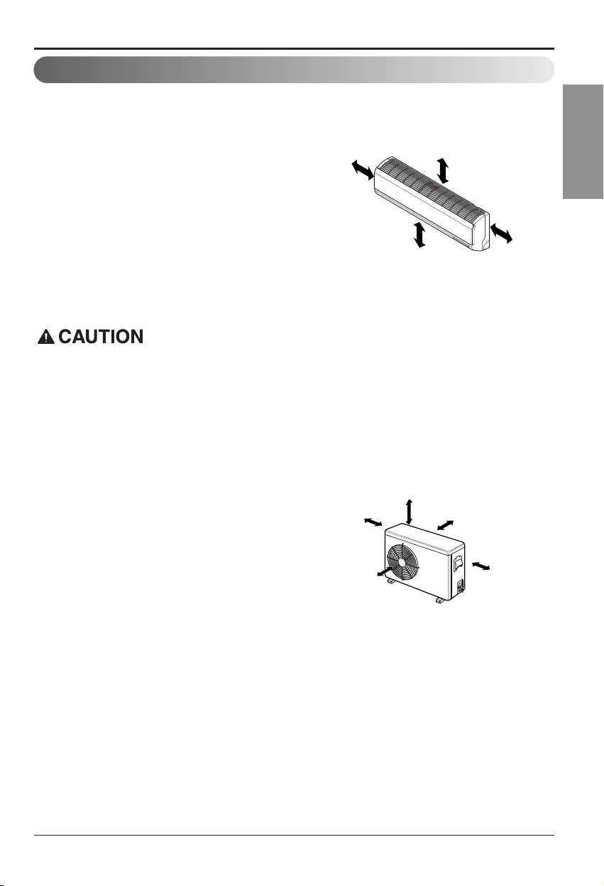
Outdoor unit
1. If an awning is built over the unit to prevent
direct sunlight or rain exposure, make sure
that heat radiation from the condenser is not
restricted.
2. Ensure that the space around the back and
sides is more than 10cm(3.9in). The front of
the unit should have more than 70cm(27.6in)
of space.
3. Do not place animals and plants in the path
of the warm air.
4. Take the air conditioner weight into account
and select a place where noise and vibration
are minimum.
5. Select a place so that the warm air and noise
from the air conditioner do not disturb
neighbors.
Rooftop Installations
If the outdoor unit is installed on a roof structure, be sure to level the unit. Ensure the roof structure
and anchoring method are adequate for the unit location. Consult local codes regarding rooftop
mounting.
If the outdoor unit is installed on roof structures or walls, this may result in excessive noise and
vibration, and may be also classed as non serviceable installation.
Indoor unit
1. Do not have any heat or steam near the unit.
2. Select a place where there are no obstacles
in front of the unit.
3. Make sure that condensation drainage can be
conveniently routed away.
4. Do not install near a doorway.
5. Ensure that the space around the left and
right of the unit is more than 30cm(11.8in).
Theunitshouldbeinstalledashighonthe
wall as possible, allowing a minimum of
12cm(4.7in) from ceiling.
6.Useastudfindertolocatestudstoprevent
unnecessary damage to the wall.
Select The Best Location
Install the indoor unit on the wall where the height from the floors more than 2.3meters(7.6ft).
A minimum pipe run of 7.5meters(24.6ft) is required to minimize vibration and excessive noise.
More than
12cm(4.7in)
More than
30cm(11.8in)
More than
30cm(11.8in)
More than 8ft(2.4m)
More than
10cm(3.9in)
More than
10cm(3.9in)
More than
60cm(23.6in)
More than
60cm(23.6in)
More than
70cm(27.6in)
Page 14
14 Room Air Conditioner
Installation
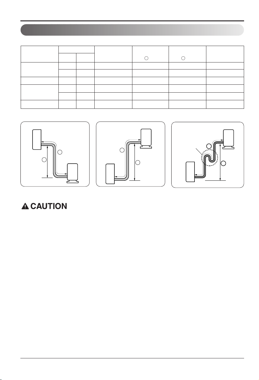
Piping Length And Elevation
• Capacity is based on standard length and maximum allowance length is on the basis of
reliability.
• Oil trap should be installed every 5~7meters (16.4~23.0ft).
Pipe Size
Capacity
(Btu/h)
Suction
Evap
Max.
length
A m(ft)
Additional Refrigerant
g/m(oz/ft)
Max.
Elevation
B m(ft)
Standard
Length
m(ft)
In case more than 5m(16.4ft)
Outdoor unit
Indoor unit
A
B
Outdoor unit
Indoor unit
A
B
A
Oil trap
Outdoor unit
Indoor unit
B
9k
3/8" 1/4" 7.5(25) 7.5(25) 15(49) 20(0.22)
1/2" 1/4" 7.5(25) 7.5(25) 15(49) 20(0.22)
12k 1/2" 1/4" 7.5(25) 7.5(25) 15(49) 20(0.22)
18k
1/2" 1/4" 7.5(25) 15(49) 30(98) 20(0.22)
5/8" 1/4" 7.5(25) 7.5(25) 15(49) 20(0.22)
24k 5/8" 1/4" 7.5(25) 7.5(25) 15(49) 20(0.22)
Page 15
Installation Manual 15
ENGLISH
Installation
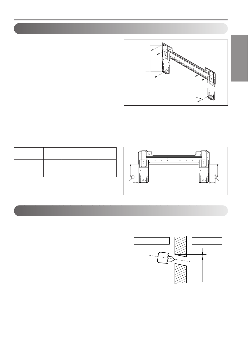
The wall you select should be strong and solid
enough to prevent vibration
1. Mount the installation plate on the wall with
type "A" screws. If mounting the unit on a
concrete wall, use anchor bolts.
• Mount the installation plate horizontally by
aligningthecenterlineusingalevel.
2. Measure the wall and mark the centerline. It is also important to use caution concerning the
location of the installation plate-routing of the wiring to power outlets is through the walls typically.
Drilling the hole through the wall for piping connections must be done safely.
How To Mount Installation Plate
Chassis
Hook
Installation Plate
Type “A”
• Drill the piping hole with a ø70mm(2.76in)
hole core drill. Drill the piping hole at either
the right or the left with the hole slightly
slantedtotheoutdoorside.
Drill a Hole In The Wall
5-7mm
(0.2~0.3")
Indoor
WALL
Outdoor
ABCD
S4 50 105 59 105
SE 65 110 85 110
S5 95 122 235 122
CHASSIS
(Grade)
Distance (mm)
D
C
Ø70mm
Left rear piping Right rear piping
Installation plate
A
B
Ø70mm
Page 16
16 Room Air Conditioner
Installation
Flaring Work
Cut the pipes and the cable.
1. Use the piping kit accessory or the pipes
purchased locally.
2. Measure the distance between the indoor and
the outdoor unit.
3. Cut the pipes a little longer than measured
distance.
4. Cut the cable 1.5m(59.1in) longer than the
pipe length.
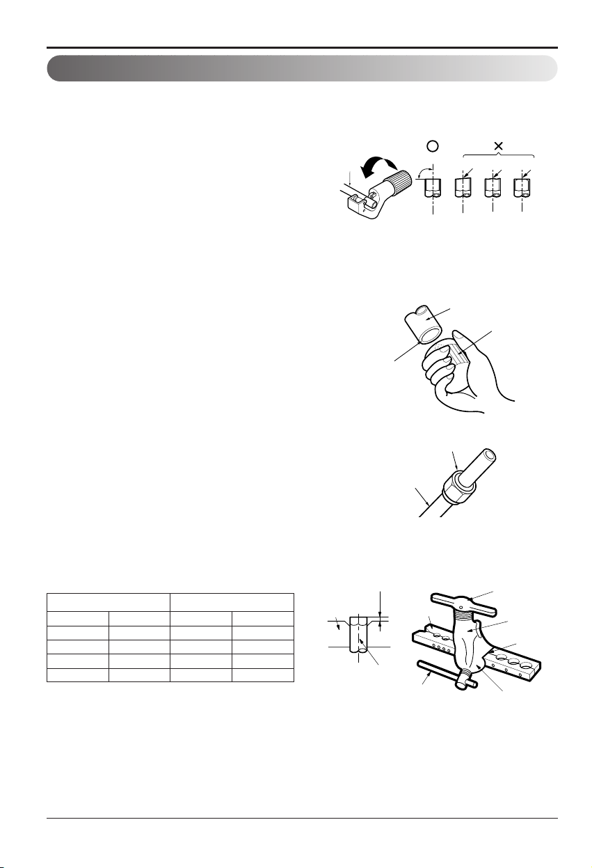
Burrs removal
1. Completely remove all burrs from the cut cross
section of pipe/tube.
2. Put the end of the copper tube/pipe in a
downward direction as you remove burrs in
order to avoid dropping burrs into the tubing.
Putting nut on
• Remove flare nuts attached to indoor and
outdoor unit, then put them on pipe/tube having
completed burr removal.
(not possible to put them on after flaring work)
Flaring work
• Carry out flaring work using flaring tool as
shown below.
Main cause for gas leakage is due to defect in flaring work. Carry out correct flaring work in the
following procedure.
mm inch mm inch
Ø6.35 1/4 0~0.5 0~0.020
Ø9.52 3/8 0~0.5 0~0.020
Ø12.7 1/2 0~0.5 0~0.020
Ø15.88 5/8 0~1.0 0~0.039
Outside diameter A
Copper
pipe
90¡
Slanted Uneven Rough
Bar
Copper pipe
Clamp handle
Red arrow mark
Cone
Yoke
Handle
Bar
"A"
Pipe
Reamer
Point down
Firmly hold copper pipe in a die in the
dimension shown in the table above.
Flare nut
Copper tube
Page 17
Installation Manual 17
ENGLISH
Installation
Indoor
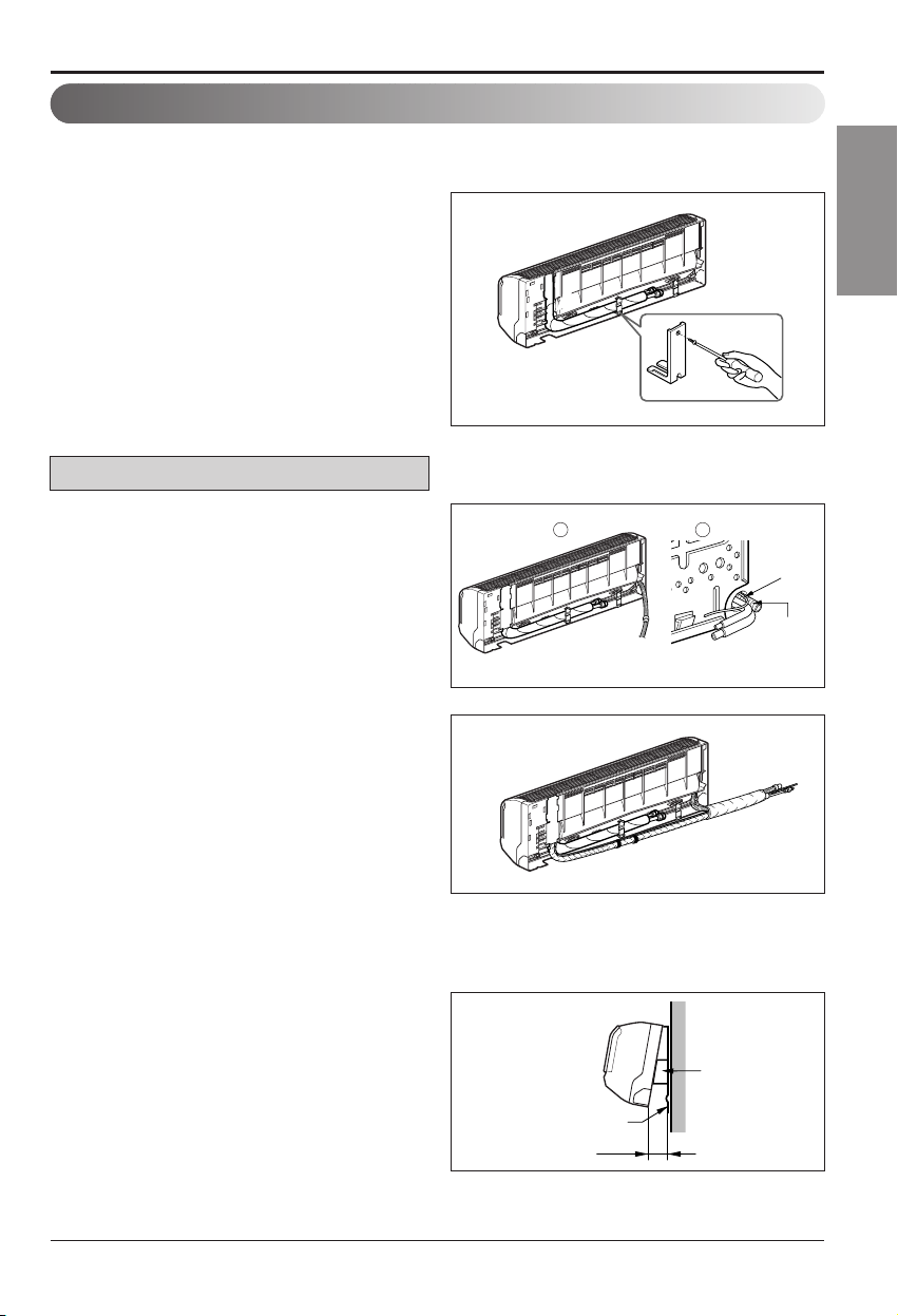
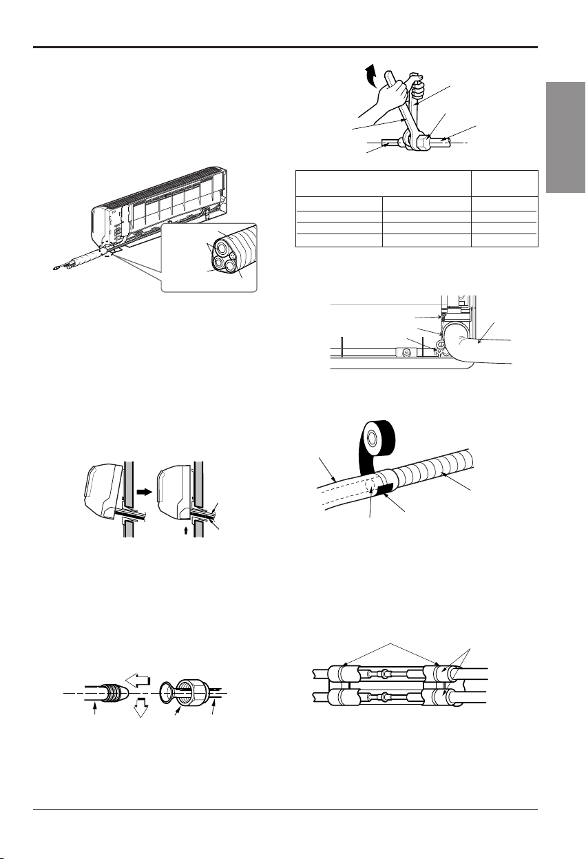
1. Prepare the indoor unit's piping and drain hose for installation through the wall.
2. Remove the plastic tubing retainer(see the
illustration by) and pull the tubing and drain
hose away from chassis.
3. Replace only the plastic tubing holder 1, not
the holder 2 in the original position.
Route the indoor tubing and the drain hose in
the direction of rear left.
Insert the connecting cable into the indoor unit
from the outdoor unit through the piping hole.
• Do not connect the cable to the indoor unit.
• Make a small loop with the cable for easy
connection later.
Tape the tubing, drain hose and the connecting
cable. Be sure that the drain hose is located at the
lowest side of the bundle. Locating at the upper side
can cause drain pan to overflow inside the unit.
NOTE: If the drain hose is routed inside the room,
insulate the hose with an insulation material* so that
dripping from "sweating"(condensation) will not
damage furniture or floors.
*Foamed polyethylene or equivalent is
recommended.
Indoor unit installation
• Hook the indoor unit onto the upper portion of
the installation plate.(Engage the three hooks
of the rear top and rear lower of the indoor unit
with the upper edge and lower edge of the
installation plate.) Ensure that the hooks are
properly seated on the installation plate by
moving it left and right.
Connecting the Piping
For left rear piping
Connecting The Piping
1 2
Indoor unit
Installation plate
8cm
Spacer
Connecting
cable
Drain pipe
Page 18
18 Room Air Conditioner
Installation
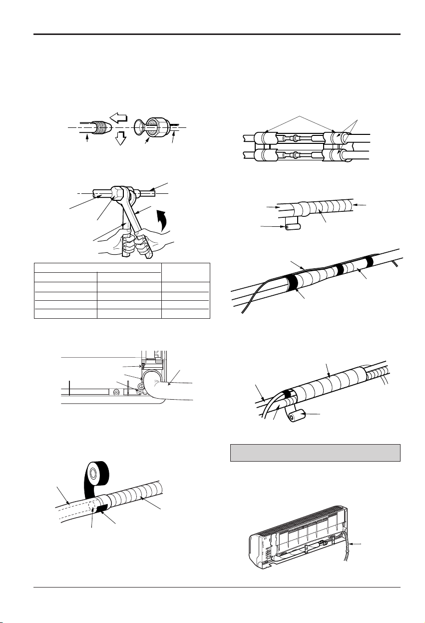
Wrap the insulation material around the
connecting portion.
• Overlap the connection pipe insulation material
and the indoor unit pipe insulation material. Bind
them together with vinyl tape so that there is no
gap.
Route the indoor tubing and the drain hose to
the required piping hole position.
Plastic bands
Insulation material
Connection pipe
Flare nut
Indoor unit tubing
Torque wrench
Spanner (fixed)
Vinyl tape(narrow)
Adhesive
Drain pipe
Indoor unit drain hose
• When extending the drain hose at the indoor unit,
install the drain pipe.
• Mount the clamp on the boss with a type "B"
screw.(SE-H/P: 9k, 12k C/O: 12k)
• Tighten the flare nut with a wrench.
• Wrap the area which accommodates the rear
piping housing section with vinyl tape.
For right rear piping
Connecting the pipings to the indoor unit
and drain hose to drain pipe.
• Put a couple drops of refrigerant oil on the face of
the flare before assembling taking care not to add
any contaminants.
• Align the center of the pipings and sufficiently
tighten the flare nut by hand.
Indoor unit tubing Flare nut Pipings
Drain hose
Ø6.35 1/4 1.8
Ø9.52 3/8 4.2
Ø12.7 1/2 5.5
Ø15.88 5/8 6.6
Outside diameter
mm inch
Torque
Vinyl tape(narrow)
Connection
pipe
Connecting cable
Vinyl tape
(wide)
Wrap with vinyl tape
Indoor
unit pipe
Pipe
• Bundle the piping and drain hose together by
wrapping them with vinyl tape over the range
within which they fit into the rear piping housing
section.
Wrap with vinyl tape
Drain hose
Pipe
Vinyl tape(wide)
Type "B" screw
Clamp
Boss
Drain hose
Page 19
Installation Manual 19
ENGLISH
Installation
Insert the connecting cable into the indoor unit.
• Don't connect the cable to the indoor unit.
• Make a small loop with the cable for easy
connection later.
Tape the drain hose and the connecting cable.
• Connecting cable
Connecting the pipings to the indoor unit and
the drain hose to drain pipe.
• Put a couple drops of refrigerant oil on the face of
the flare before assembling taking care not to add
any contaminants
• Align the center of the pipings and sufficiently
tighten the flare nut by hand.
• Tighten the flare nut with a wrench.
Indoor unit tubing Flare nut Pipings
Torque wrench
Indoor unit tubing
Spanner (fixed)
Connection pipe
Flare nut
Indoor unit installation
• Hook the indoor unit onto the upper portion of
the installation plate.(Engage the three hooks of
the rear top and rear lower of the indoor unit with
the upper edge and lower edge of the installation
plate.) Ensure that the hooks are properly
seated on the installation plate by moving it left
and right.
Wrap the insulation material around the
connecting portion.
•
Overlap the connection pipe heat insulation and the
indoor unit pipe heat insulation material. Bind them
together with vinyl tape so that there is no gap.
Plastic bands
Insulation material
Vinyl tape
Adhesive
Drain hose
Indoor unit drain hose
(narrow)
• When extending the drain hose at the indoor unit,
install the drain pipe.
Connecting
pipe
Connecting cable
Tape
Drain hose
Drain hose
Connecting
cable
Ø6.35 1/4 1.8
Ø9.52 3/8 4.2
Ø12.7 1/2 5.5
Ø15.88 5/8 6.6
Outside diameter Torque
• Mounttheclamponthebosswithatype"B"
screw.(SE-H/P: 9k, 12k C/O: 12k)
Type "B" screw
Clamp
Boss
Drain hose
Page 20

20 Room Air Conditioner
Installation
Reroute the pipings and the drain hose
across the back of the chassis.
Reroute the pipings and the drain hose
across the back of the chassis.
Drain hose
Vinyl tape(narrow)
Pipe
Wrap with
vinyl tape(wide)
• Bundle the piping and drain hose together by
wrapping them with cloth tape over the range within
which they fit into the rear piping housing section.
Piping for
passage through
piping hole
Drain hose
Connecting
cable
• Wrap the area which accommodates the rear
piping housing section with vinyl tape.
Vinyl tape(narrow)
Connection
pipe
Connecting cable
Indoor
unit piping
Pipe
Vinyl tape
(wide)
Wrap with vinyl tape
Page 21
Installation Manual 21
ENGLISH
Installation
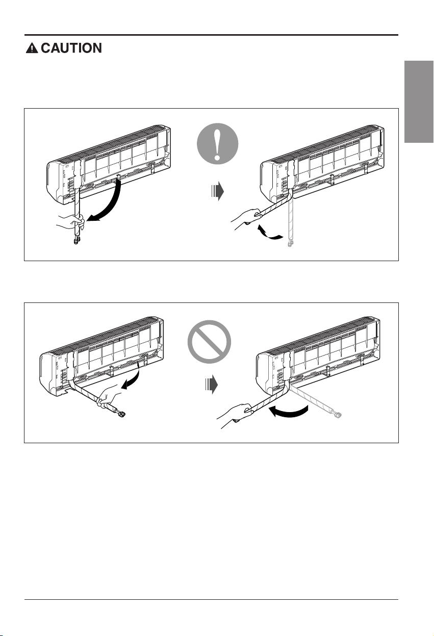
Installation Information. For left piping. Follow the instruction below.
Correct case
• Press on the upper side of clamp and unfold the tubing to downward slowly.
Incorrect case
• Following bending type from right to left may cause damage to the tubing.
Page 22
22 Room Air Conditioner
Installation
Put a couple drops of refrigerant oil on the face
of the flare before assembling taking care not to
add any contaminants.
Align the center of the pipings and sufficiently
tighten the flare nut by hand.
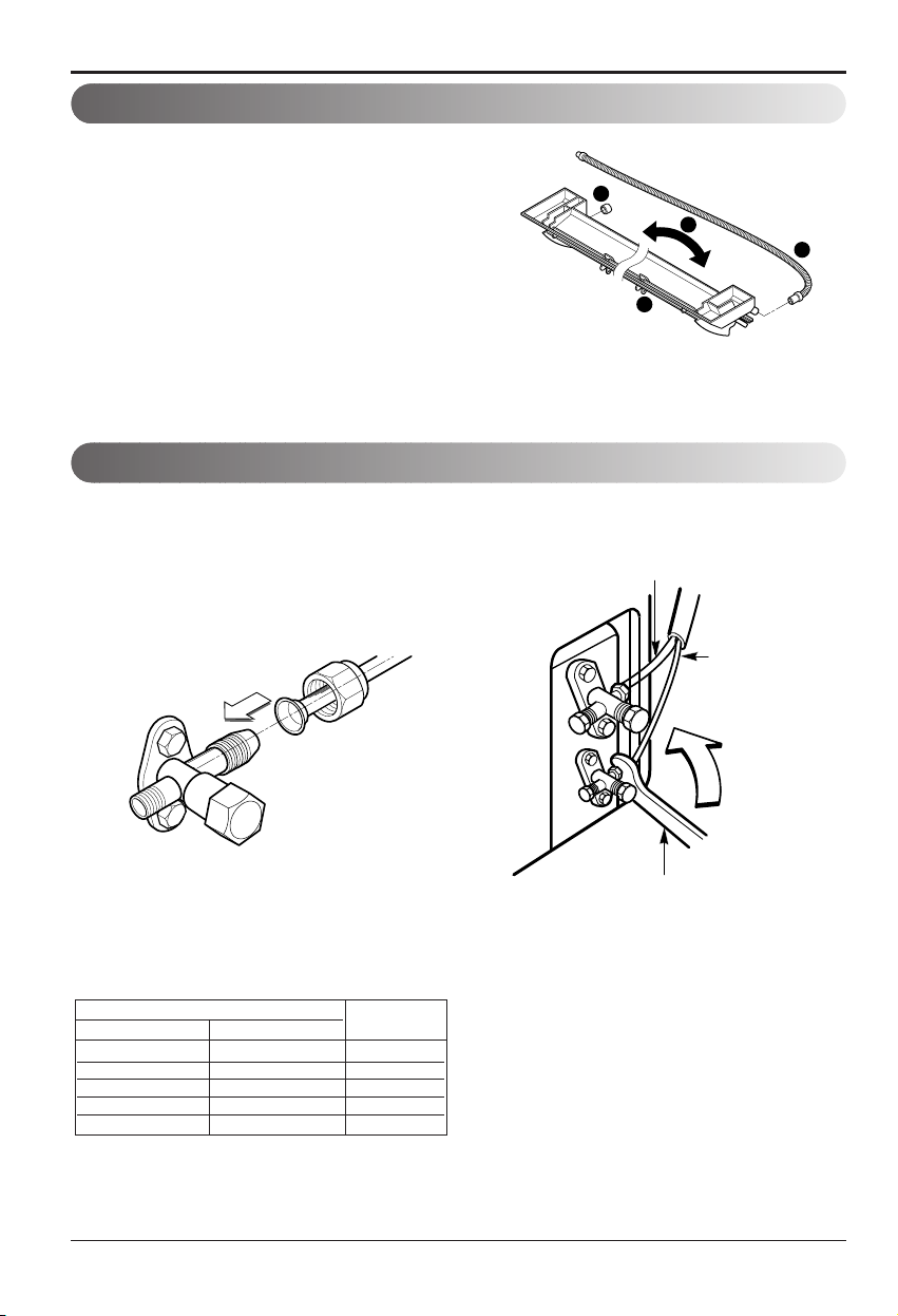
• The drain hose can be connected at two different
positions. Use the most convenient position and, if
necessary, exchange the position of the drain pan,
rubber cap and the drain hose.
➊ Drain pan
➋ Rubber cap
➌ Drain hose
➍ Exchange if necessary
• Remove the drain hose.
• Securely insert both the rubber plug and drain
hose into the drain outlets.
Be sure the rubber the cap is securely fastened so
that there is no leakage.
Finally, tighten the flare nut with torque wrench
until the wrench clicks.
• When tightening the flare nut with torque wrench,
ensure the direction for tightening follows the arrow
on the wrench.
Outdoor unit
Suction Line piping
(Bigger diameter)
Evaporator Line
piping
(Smaller
diameter)
Torque wrench
1
2
3
4
Connecting the PipingConnection Of The Drain Hose
Connecting the PipingConnection Of Piping -Outdoor
Ø6.35 1/4 1.8
Ø9.52 3/8 4.2
Ø12.7 1/2 5.5
Ø15.88 5/8 6.6
Ø19.05 3/4 6.6
Outside diameter
mm inch
Torque
Page 23

Installation Manual 23
ENGLISH
Installation
Connecting the PipingConnection Of The Cable
1
Indoor Unit Outdoor Unit
2
3
4
1
2
3
4
5
6
G
To
branch
circuit
Ground
Power supply
a
L1
*
L2
Connecting cable(Low voltage)
b
Terminal
(4P)
Terminal
(6P)
Outdoor unit
Wiring Diagram
Terminal block
Over 5mm
(0.2")
Cover control
Conduit panel
Connecting
cable
Power supply
cord
*
L1 is neutral for 115V models.
1. Remove the cover control from the unit by
loosening the 3 screws.
2. Dismount caps on the conduit panel.
3. Temporarily mount the conduit tubes on the
conduit panel.
4. Properly connect both the power supply and
low voltage lines to the corresponding
terminals on the terminal block.
5. Ground the unit in accordance with local
codes.
6. Be sure to size each wire allowing several
inches longer than the required length for
wiring.
7. Use lock nuts to secure the conduit tubes.
1. shows field wiring.
2. Separately wire the high and low voltage line.
3. Use heat-proof electrical wiring capable of
withstanding temperatures up to 167°F.
4. Use outdoor and waterproof connection cable
rated more than 300V for the connection between
indoor and outdoor unit.
(For example, Type STOW)
• Be sure to comply with local codes while
running the wire from the indoor unit to the
outdoor unit(size of wire and wiring method,
etc).
• Everywiremustbeconnectedfirmly.
• No wire should be allowed to touch
refrigerant tubing, the compressor or any
moving parts.
Connector trade size for this unit is 1/2"
for instructions on connecting depending on
thewiretypeyouareusing.
WARNING
NOTE
Power Supply
Model
Powe r sour ce
9K 1ø, 115V 14 18 15A
12K 1ø, 115V 14 18 20A
18K 1ø, 230/208V 14 18 20A
24K 1ø, 230/208V 12 18 25A
AWG(MI N.)
Fuse or breaker
Capacity
NOTE
Page 24
24 Room Air Conditioner
Installation
After the confirmation of the above conditions, prepare the wiring as follows:
1)
Never fail to have an individual power circuit specifically for the air conditioner. As for
the method of wiring, be guided by the circuit diagram posted on the inside of control
cover.
2) The screw which fasten the wiring in the casing of electrical fittings are liable to
come loose from vibrations to which the unit is subjected during the course of
transportation. Check them and make sure that they are all tightly fastened. (If they
are loose, it could cause burn-out of the wires.)
3) Specification of power source.
4) Confirm that electrical capacity is sufficient.
5) Confirm that the starting voltage is maintained at more than 90 percent of the rated
voltage marked on the name plate.
6) Confirm that the cable thickness is as specified in the power source specification.
(Particularly note the relation between cable length and thickness.
7) Always install an GFCI circuit breaker in a wet or moist area.
8) The following would be caused by voltage drop.
• Vibration of a magnetic switch, which will damage the contact point, open fuse, disturbance of the
normal function of the overload.
9) The means for disconnection from a power supply shall be incorporated in the fixed
wiring and have an air gap contact separation of at least 3mm(0.12in) in each
active(phase) conductors.
CAUTION
Page 25
Installation Manual 25
ENGLISH
Installation
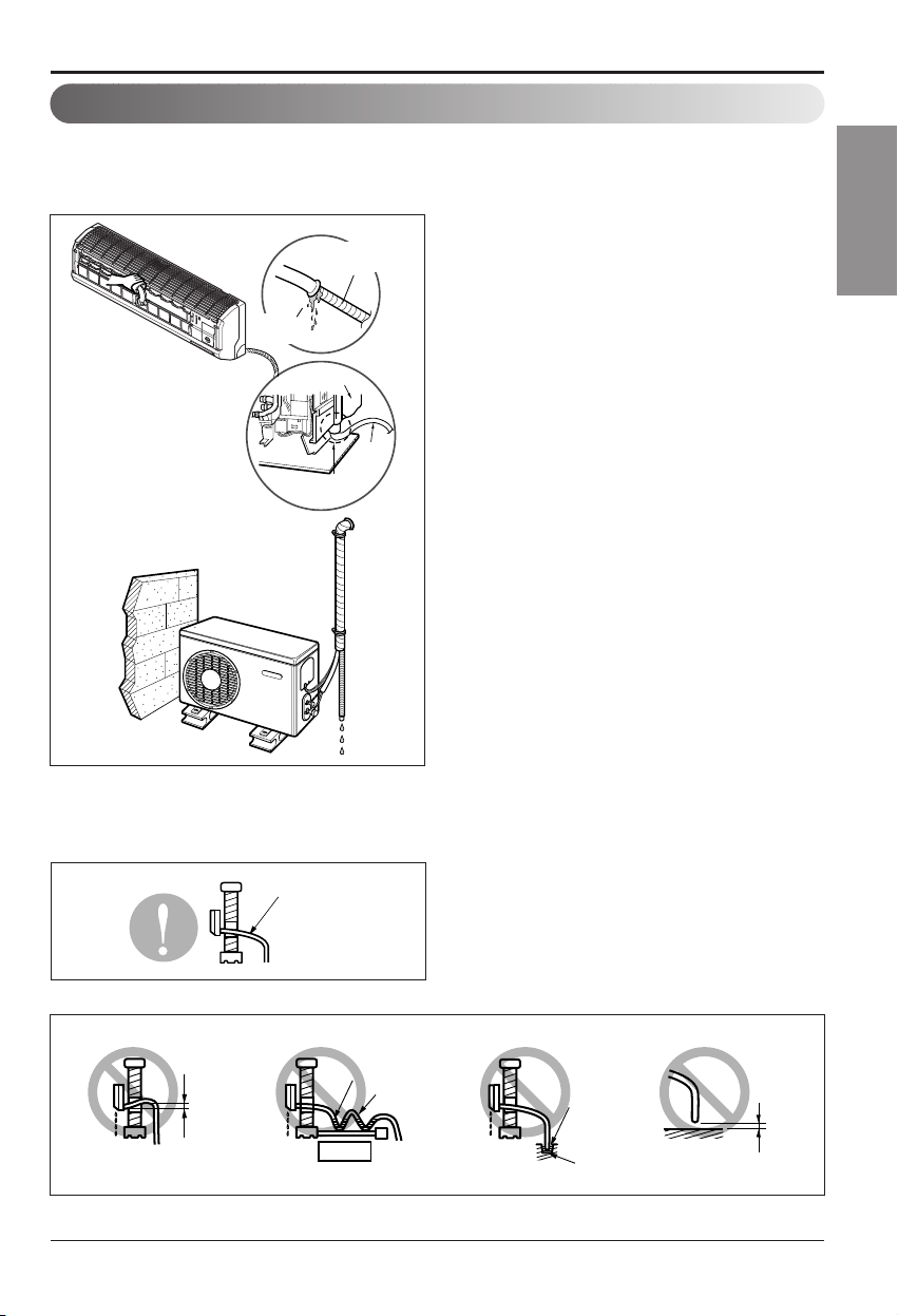
Checking The Drainage
• Pour a glass of water on the drain pan.
• Ensure the water flows through the drain hose of the indoor unit without any leakage and goes out the drain
exit.
Drain piping
• The drain hose should point downward for easy drain flow.
• Avoid these situations.
Drain pan
Drain
hose
Leakage
checking
Connecting area
drain hose
Leakage
checking
Downward slope
Water
leakage
Accumulated
drain water
Waving
Air
Do not raise
Water
leakage
Water
leakage
Tip of drain hose
dipped in water
Ditch
Less than
50mm gap
Page 26
26 Room Air Conditioner
Installation
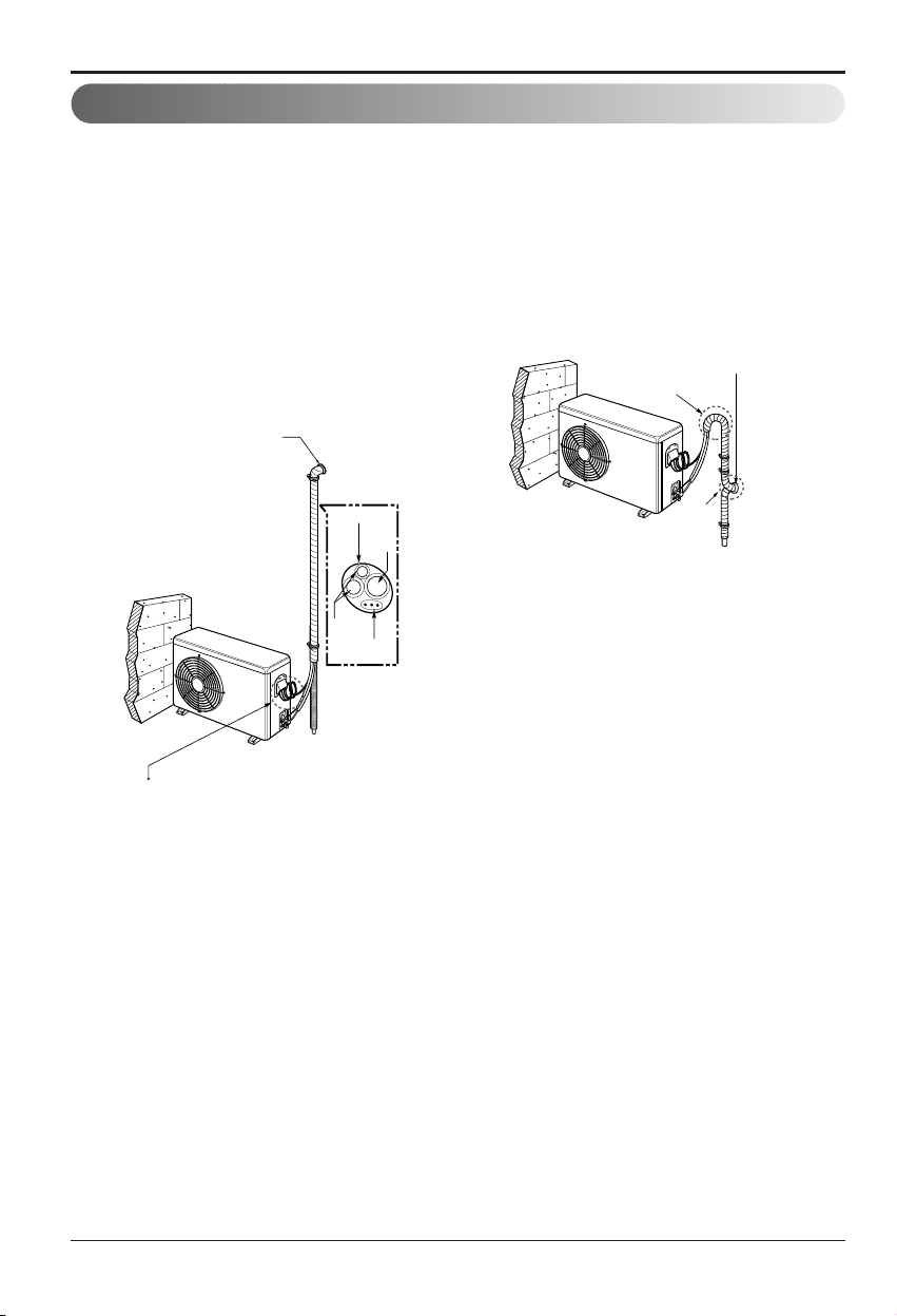
Forming The Piping
Form the piping by wrapping the connecting
portion of the indoor unit with insulation material
and secure it with two kinds of vinyl tapes.
• If you want to connect an additional drain hose, the
end of the drain outlet should be routed above the
ground. Secure the drain hose appropriately.
In cases where the outdoor unit is installed
below the indoor unit perform the following.
•
Tape the piping, drain hose and connecting cable
from down to up.
•
Secure the tapped piping along the exterior wall
using saddle or equivalent.
Taping
Drain
hose
Pipings
Connecting
cable
Trap is required to prevent water
from entering into electrical parts.
Seal small openings
around pipings with a
gum type sealer.
In cases where the Outdoor unit is installed
above the Indoor unit perform the following.
•
Tape the piping and connecting cable from down to
up.
•
Secure the taped piping along the exterior wall. Form
atraptopreventwaterenteringtheroom.
•
Fix the piping onto the wall by saddle or equivalent.
Seal a small opening
around the pipings
with gum type sealer.
Trap
Trap
Page 27
Installation Manual 27
ENGLISH
Air Purging
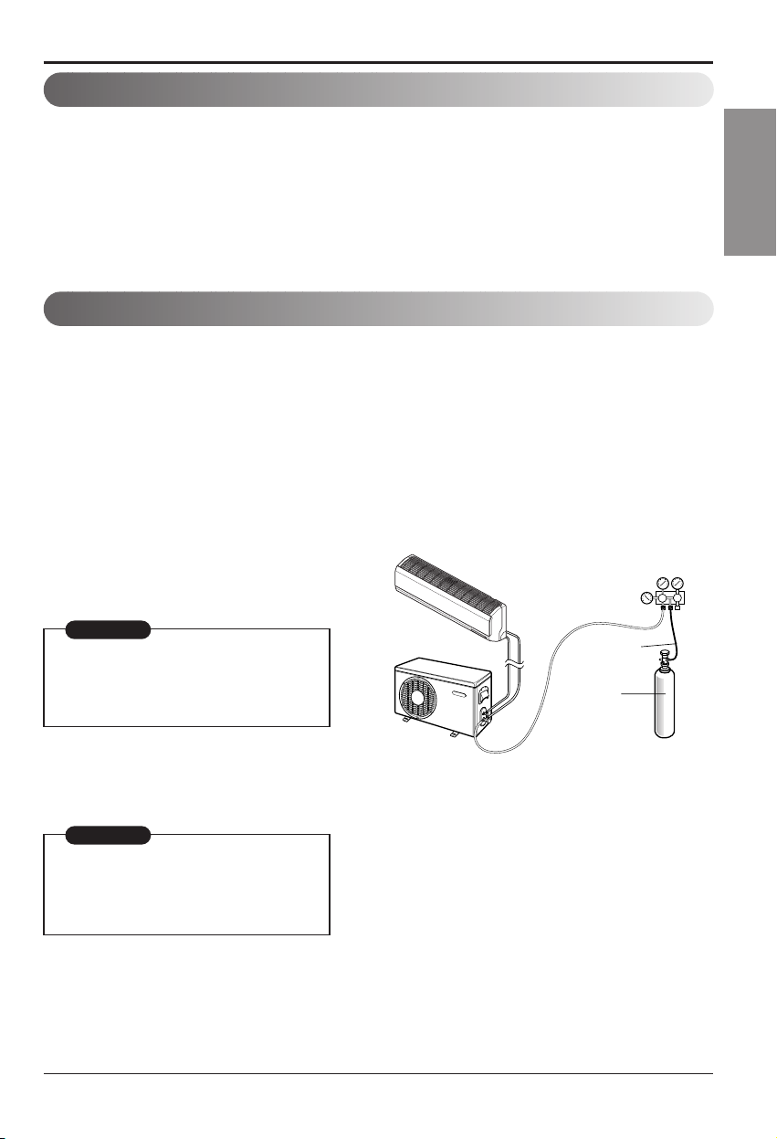
Air purging With Vacuum Pump
Lo Hi
Indoor unit
Outdoor unit
Manifold valve
Charge hose
Nitrogen gas
cylinder(in vertical
standing position)
Pressure
gauge
Air and moisture remaining in the refrigerant system have undesirable effects as indicated below.
• Pressure in the system rises.
• Operating current rises.
• Cooling(or heating) efficiency drops.
• Moisture in the refrigerant circuit may freeze and block capillary tubing.
• Water may lead to corrosion of parts in the refrigeration system.
Therefore, the indoor unit and tubing between the indoor and outdoor unit must be leak tested and evacuated
to remove any noncondensables and moisture from the system.
Preparation
• Check that each tubing(both liquid and gas side
tubes) between the indoor and outdoor units have
been properly connected and all wiring for the test
run has been completed. Remove the service
valve caps from both the gas and the liquid side
on the outdoor unit. Note that both the liquid and
the gas side service valves on the outdoor unit are
kept closed at this stage.
Leak test
• Connect the manifold valve(with pressure
gauges) and dry nitrogen gas cylinder to this
service port with charge hoses.
• Pressurize the system to no more than 150 P.S.I.G.
with dry nitrogen gas and close the cylinder valve
when the gauge reading reached 150 P.S.I.G. Next,
test for leaks with liquid soap.
• Do a leak test of all joints of the tubing(both indoor
and outdoor) and both gas and liquid side service
valves.
Bubbles indicate a leak. Be sure to wipe off the soap
with a clean cloth.
• After the system is found to be free of leaks, relieve
the nitrogen pressure by loosening the charge hose
connector at the nitrogen cylinder. When the system
pressure is reduced to normal, disconnect the hose
from the cylinder.
Be sure to use a manifold valve for air
purging. If it is not available, use a stop
valve for this purpose. The "Hi" knob of
the manifold valve must always be kept
close.
To avoid nitrogen entering the refrigerant system in
a liquid state, the top of the cylinder must be higher
than its bottom when you pressurize the system.
Usually, the cylinder is used in a vertical standing
position.
CAUTION
CAUTION
Installation
Page 28

28 Room Air Conditioner
Installation
Evacuation
• Connect the charge hose end described in the
preceding steps to the vacuum pump to
evacuate the tubing and indoor unit.
Confirm the "Lo" knob of the manifold valve is
open. Then, run the vacuum pump.
The operation time for evacuation varies with
tubing length and capacity of the pump. The
following table shows the time required for
evacuation.
• When the desired vacuum is reached, close the
"Lo" knob of the manifold valve and stop the
vacuum pump.
Finishing the job
• With a service valve wrench, turn the valve
stem of liquid side valve counter-clockwise to
fully open the valve.
• Turn the valve stem of gas side valve counterclockwise to fully open the valve.
• Loosen the charge hose connected to the gas
side service port slightly to release the pressure,
then remove the hose.
• Replace the flare nut and its bonnet on the gas
side service port and fasten the flare nut securely
with an adjustable wrench. This process is very
important to prevent leakage from the system.
• Replace the valve caps at both gas and liquid side
service valves and fasten them tight.
This completes air purging with a vacuum pump.
The air conditioner is now ready to test run.
(1) Remove the caps from the gas side and
liquid side valves.
(2) Remove the service-port cap from the gas
side valve.
(3) To open the gas side valve turn the valve
stem counterclockwise approximately 90°,
wait for about 2~3 seconds, and close it.
(4) Apply a soap water or a liquid neutral
detergent on the indoor unit connection or
outdoor unit connections by a soft brush to
check for leakage of the connecting points
of the piping.
(5) If bubbles come out, the pipes have
leakage.
Soap water method
Suction Line
Evaporator Line
Cap
Hexagonal wrench
3-way valve
(Open)
3-way valve
(Close)
Required time for evacuation when 30 gal/h
vacuum pump is used
10 min. or more 15 min. or more
If tubing length is less
than 10m (33 ft)
if tubing length is longer
than 10m (33 ft)
Indoor unit
Outdoor unit
Lo Hi
Manifold valve
Vacuum pump
Pressure
gauge
Open
Close
Page 29

Installation Manual 29
ENGLISH
Installation
Charging
■ Each outdoor unit is factory charged (nameplate charge) for the evaporator as well as a 7.5m(25ft) line
set. Any time a line set is used either shorter or longer then the nominal 7.5m(25ft) line set length the
refrigerant charge has to be adjusted.
■ Whether the line set is made shorter or longer you must adjust the charge based on how many ft of tubing
are either added or removed based on 30g(0.32oz) of R-410A per meter(foot).
Example: A 30ft line set is used
5 additional ft X 0.22 ounce per foot= add 1.1 ounces of R-410A
Important:
If you are ever uncertain of the unit charge, reclaim, evacuate and weigh in the correct charge using the unit
nameplate charge adjusting for line sets longer or shorter than 7.5m(25ft).
Confirm the refrigerant R-410A. Use manifold gauge and hose for R-410A.
Pipe Size
Capacity
(Btu/h)
Suction
Evap
Max.
length
A m(ft)
Additional Refrigerant
g/m(oz/ft)
Max.
Elevation
B m(ft)
Standard
Length
m(ft)
9k
3/8" 1/4" 7.5(25) 7.5(25) 15(49) 20(0.22)
1/2" 1/4" 7.5(25) 7.5(25) 15(49) 20(0.22)
12k 1/2" 1/4" 7.5(25) 7.5(25) 15(49) 20(0.22)
18k
1/2" 1/4" 7.5(25) 15(49) 30(98) 20(0.22)
5/8" 1/4" 7.5(25) 7.5(25) 15(49) 20(0.22)
24k 5/8" 1/4" 7.5(25) 7.5(25) 15(49) 20(0.22)
Page 30

30 Room Air Conditioner
Test Running
Outside ambient TEMP. The pressure of the gas side service valve
95°F(35°C)
8.5~9.5kg/cm2G(120~135 P.S.I.G.)
Settlement of outdoor unit
■
Anchor the outdoor unit with a bolt and
nut(ø10mm(0.39in) tightly and horizontally on a
concrete or rigid mount.
■
When installing on the wall, roof or rooftop, anchor
the mounting base securely with a nail or wire
assuming the influence of wind and earthquake.
■
In the case when the vibration of the unit is
conveyed to the hose, secure the unit with an antivibration rubber.
1.
Check that all tubing and wiring have been
properly connected.
2.
Check that the gas and liquid side service valves
are fully open.
Prepare remote control
1. Remove the battery cover
by pulling it according to the
arrow direction.
2. Insert new batteries making
sure that the (+) and (–)of
battery are installed correctly.
3. Reattach the cover by
pushing it back into position.
NOTE:
• Use 2 AAA(1.5volt) batteries. Do not use
rechargeable batteries.
• Remove the batteries from the remote control if
the system is not going to be used for a long
time.
Evaluation of the performance
Operate unit for 15~20 minutes, then check the
system refrigerant charge:
1.
Measure the pressure of the gas side service
valve.
2.
Measure the temperature of the intake and
discharge of air.
NOTE: If the actual pressure are higher than
shown, the system is most likely overcharged, and charge should be removed. If
the actual pressure are lower than shown,
the system is most likely undercharged, and
charge should be added.
The air conditioner is now ready for use.
Bolt
Tubing connection
This is performed when the unit is to be
relocated or the refrigerant circuit is
serviced.
Pump Down means collecting all refrigerant in
the outdoor unit without loss of refrigerant.
CAUTION:
Be sure to perform Pump Down procedure
with the unit cooling mode.
Pump Down Procedure
1. Connect a low-pressure gauge manifold hose
to the charge port on the gas side service
valve.
2. Open the gas side service valve halfway and
purge the air from the manifold hose using the
refrigerant gas.
3. Close the liquid side service valve(all the way
in).
4. Turn on the unit's operating switch and start
the cooling operation.
5. When the low-pressure gauge reading
becomes 1 to 0.5kg/cm2G(14.2 to 7.1
P.S.I.G.), fully close the gas side valve stem
and then quickly turn off the unit. At that time,
Pump Down has been completed and all
refrigerant will have been collected in the
outdoor unit.
PUMP DOWN
3. Ensure the difference between the intake
temperature and the discharge is more than
46.4°F(8°C) (Cooling) or (Heating).
4. For reference; the gas side pressure of optimum
condition is as below.(Cooling)
Discharge
temperature
Discharge air
Intake temperature
Test Running
Page 31

FRANÇAIS
Climatiseur
MANUEL D’INSTALLATION
IMPORTANT
• Veuillez lire au complet ce manuel d’instructions avant
installer le produit.
• Si le cordon d’alimentation est endommagé, son
remplacement ne doit être accompli que par du personnel
autorisé.
• Conformément aux standards nationaux sur le câblage,
l’installation ne doit être effectuée que par du personnel
autorisé.
• Après l’avoir lu au complet, veuillez conserver ce manuel
d’installation pour référence ultérieure.
Page 32

2 Climatiseur
Manuel d’installation du Climatiseur
TABLE DES MATIÈRES
❏
Plateau d’installation
❏
Quatre vis du type “A”
❏
Câble de branchement
❏
Tuyaux : Ligne de succion
..
5/8"
Ligne d’évaporation
.............
3/8"
(Voir page 13)
❏
Matériaux d’isolation
❏
Tuyau supplémentaire de
vidange (diamètre extérieur
15,5 mm(0.61in))
❏
Deux vis de type “B”
❏
Niveau
❏
Tournevis
❏
Perceuse électrique
❏
Pointe de perceuse
(ø70mm(2.76in))
❏
Ensemble outil d’évasement
❏
Clés torsiométriques
4,2 kg.m, 6,6 kg.m
(différentes selon le numéro du
modèle)
(Voir page 17)
❏
Clé ............................. anglaise
❏
Un verre d’eau
❏
Tournevis
❏
Clé hexagonale (4 mm(0.16in))
❏
Indicateur de fuite de gaz
❏
Pompeàvide
❏
Manomètre
❏
Manuel utilisateur
❏
Thermomètre
❏
Support télécommande
Conditions requises
pour l’installation
Composants nécessaires
Outils nécessaires
Mesuresdesécurité..................3
Introduction................................9
Symboles utilisés dans ce
manuel ....................................9
Caractéristiques......................9
Installation................................10
Pièces d’installation ..............10
Outils d’installation................10
Carte d’installation ................11
Vérifiez le gaz réfrigérant......12
Sélectionnez le meilleur
emplacement ........................13
Elévation et longueur des
tuyaux ...................................14
Comment fixer la plaque
d’installation ..........................15
Pratiquez un trou dans
le mur....................................15
Travail d’évasage ..................16
Raccordement de la
tuyauterie ..............................17
Connexion du tuyau de
drainage................................22
Connexion des canalisations
Externe .................................22
Raccordement des câbles ....23
Contrôle de la vidange..........25
Façonnage des tuyaux..........26
Vidange air............................27
Vidange air avec pompe
à vide ....................................27
Charge ..................................29
Test de fonctionnement ..........30
Verification ............................30
Page 33

Manuel d'installation 3
FRANÇAIS
Mesures de sécurité
Pour éviter des blessures à l'utilisateur ou à d'autres personnes ainsi que des dommages matériels,
vous devez suivre les instructions ci-dessous.
■ L’utilisation incorrecte de l’appareil due à la méconnaissance des instructions provoquera des
blessures ou des dommages, dont la gravité est indiquée au moyen des symboles suivants.
■ La signification des symboles utilisés dans ce guide est indiquée ci-dessous.
Ce symbole indique la possibilité de mort ou de blessures graves.
Ce symbole indique la possibilité de blessures ou de dommages
matériels uniquement.
AVERTISSEMENT
■ Installation
Veillez à ne pas faire.
Veillez à suivre cette instruction.
Mesures de sécurité
N'utilisez des câbles
électriques ou des fiches
endommagés, ni des prises
desserrées.
• Ceci risque de provoquer un
incendie ou un choc électrique.
Pour un travail électrique,
contactez le distributeur, le
vendeur, un électricien qualifié
ou un centre de service aprèsvente agréé.
• Autrement, vous risqueriez de
provoquer un incendie ou un
choc électrique.
Utilisez toujours une fiche
d'alimentation et une prise de
courant avec borne de mise à
la terre.
• Autrement, vous risqueriez de
provoquer un choc électrique.
Installez fermement le panneau
et le couvercle du tableau de
commande.
• Autrement vous risquerez de
provoquer un incendie ou un
choc électrique.
Ne modifiez ni prolongez le
cordon d'alimentation.
• Ceci risquerait de provoquer un
incendie ou un choc électrique.
N'installez, n'enlevez ni remettez
en place l'unité vous-même (si
vous êtes un client).
• Vous pourriez provoquer un
incendie, un choc électrique, une
explosion ou vous blesser.
AVERTISSEMENT
ATTENTION
Page 34

4 Climatiseur
Mesures de sécurité
■ Fonctionnement
Prenez soin lorsque vous
déballez et installez ce produit.
• Les bords aiguisés peuvent
provoquer des blessures. Faites
attention en particulier aux bords
aiguisés.
Contactez toujours le
revendeur ou un centre de
service aprèsventeagréé pour
effectuer l'installation.
• Autrement, vous pourriez
provoquer un incendie, un choc
électrique, une explosion ou vous
blesser.
N'installez pas le produit sur
un support d'installation
défectueux.
• Ceci peut provoquer des
blessures, un accident ou bien
endommager le produit.
Assurez-vous que la zone
d'installation n'est pas abîmée
par le temps.
• Si la base s'écroule, le
climatiseur pourrait tomber avec
elle, provoquant des dommages
matériels, une défaillance du
produit et des blessures.
Installez le group interne sur la
paroi ou' la hauteur á partir du
plancher est supérieure á 8ft(2.4
métres)
• Il y a des bords aiguisés et des
piéces mobiles gui pourraient
vous blesser.
Ne pas manipuler le tuyau vousmême (utilisateur).
• Le gaz réfrigérant à haute pression
peut provoquer des blessures.
8ft(2.4m)
Assurez-vous qu'on ne tire ni
n'endommage le cordon
d'alimentation en cours du
fonctionnement de l'unité.
• Ceci risquerait de provoquer un
incendie ou un choc électrique.
Ne placez aucun objet sur le
cordon d'alimentation.
• Ceci risquerait de provoquer un
incendie ou un choc électrique.
Ne mettez en marche ni arrêtez
le climatiseur en branchant ou
débranchant la fiche
d'alimentation.
• Ceci risquerait de provoquer un
incendie ou un choc électrique.
Page 35

Manuel d'installation 5
FRANÇAIS
Mesures de sécurité
Utilisé une prise de courant
dédiée pour cet appareil.
• Autrement, vous risqueriez de
provoquer un incendie ou un
choc électrique.
Saisissez la fiche pour retirer
le cordon de la prise de
courant. Ne touchez pas la
fiche avec les mains humides.
• Ceci risquerait de provoquer un
incendie ou un choc électrique.
Ne permettez pas que de l'eau
s'écoulesurlespièces
électriques.
• Ceci pourrait provoquer un
incendie, une défaillance de
l'appareil ou un choc électrique.
Ne placez pas de plinthes ou
d'autres appareils prèsdu
cordon d'alimentation.
• Ceci pourrait provoquer un
incendie, une défaillance de
l'appareil ou un choc électrique.
Ne permettez pas que de l'eau
s'écoulesurlespièces
électriques.
• Ceci pourrait provoquer un
incendie, une défaillance de
l'appareil ou un choc électrique.
N'emmagasinez ni utilisez de
substances inflammables ou
combustibles prèsdece
climatiseur.
• Ceci entraînerait un risque
d'incendie ou de défaillance du
produit.
N'utilisez pas ce produit dans
un espace fermé
hermétiquement pendant une
longue période de temps.
• Un manque d'oxygène pourrait
survenir.
S'ilyaunefuitedegaz
inflammable, fermez le robinet à gaz
et ouvrez une fenêtre pour ventiler
la pièce avant de mettre en marche
le climatiseur. N'utilisez le téléphone
ni déplacez les interrupteurs sur les
positions marche/arrêt.
• Ceci risquerait de provoquer une
explosion ou un incendie.
Si l'unité dégage des sons, des
odeurs ou de la fumée,
débranchez-la.
• Ceci pourrait provoquer un
incendie, une défaillance de
l'appareil ou un choc électrique.
Thinner
Wax
Page 36

6 Climatiseur
Mesures de sécurité
Arrêtez le climatiseur et fermez
la fenêtre en cas de tempête ou
d'ouragan. Si possible, retirez
le produit de la fenêtre avant
que l'ouragan n'arrive.
• Autrement, vous risqueriez de
provoquer des dommages
matériels, une défaillance du
produit ou un choc électrique.
N'ouvrez pas la grille d'entréed'air
du produit alors que celui-ci est en
fonctionnement. (Ne touchez pas
le filtre électrostatique, si l'unité en
est équipée.)
•
Autrement, vous risquerez de
subir des blessures physiques, un
choc électrique ou de provoquer
une défaillance du produit.
Contactez un centre de service
après-vente agréé si le produit
est trempé (rempli d'eau ou
submergé).
• Ceci risque de provoquer un
choc électrique.
Ventilezleproduitdetemps
en temps lorsque vous
l'utilisez simultanément avec
une poêle, etc.
• Autrement, vous risquerez de
provoquer un incendie ou un
choc électrique.
Débranchez l'appareil avant de
procéder à des opérations de
nettoyage ou de maintenance
du produit.
• Autrement, vous risquerez de
provoquer un choc électrique.
Si vous n'allez pas utiliser le
produit pendant une longue
période de temps, débranchez le
cordon d'alimentation ou mettez le
disjoncteur sur la position arrêt.
• Autrement, vous risquerez
d'endommager le produit, de
provoquer une défaillance de
celui-ci ou bien une mise en
marche involontaire de l'unité.
Assurez-vous que personne ne pourra marcher
ou tomber sur l'unité extérieure.
• Ceci pourrait provoquer des blessures personnelles
et endommager le produit.
N'insérez pas les mains ou d'autres objets à
travers l'entréeoulasortied'airlorsquele
climatiseur est branché.
• Il y a des bords aiguisés et des pièces mobiles qui
pourraient vous blesser.
Page 37

Mesures de sécurité
Manuel d'installation 7
FRANÇAIS
ATTENTION
■ Installation
Vérifiez toujours s'il y a des
fuites de gaz (frigorigène) suite
à l'installation ou à la
réparation du produit.
• Des niveaux de frigorigène trop
bas peuvent provoquer une
défaillance du produit.
Installez le raccord de drainage
de manière à assurer un
drainage approprié.
• Une mauvaise connexion peut
provoquer des fuites d'eau.
Maintenez le produit de niveau
lors de son installation.
• Ceci sert àéviter des vibrations
ou des fuites d'eau.
N'installez pas le produit à un
endroit où le bruit ou l'air chaud
dégagésdel'unité extérieure
pourraient déranger les voisins.
• Ceci peut provoquer des
problèmes à vos voisins.
Faites appel à deux ou
plusieurs personnes pour
enlever et transporter ce
climatiseur.
• Evitez des blessures.
N'installez pas ce produit à un
endroit où il serait exposé
directement au vent de la mer
(pulvérisation d'eau de mer).
•
Ceci peut produire de la corrosion sur
le produit. La corrosion,
particulièrement sur les ailettes du
condenseur et de l'évaporateur, peut
provoquer un dysfonctionnement ou un
fonctionnement inefficace du produit.
N'orientez pas le flux d'air vers
les occupants de la pièce (Ne
vous asseyez pas sous le
courant d'air).
• Ceci pourrait nuire à votre santé.
N'utilisez pas ce produit pour des
objectifs spéciaux tels que la
préservation d'aliments, d'oeuvres
d'art, etc. C'est un climatiseur
grand public, non pas un système
de refroidissement de précision.
• Il y a risque de dommage à la
propriété ou pertes matérielles.
Ne bloquez pas l'entréeoula
sortie du flux d'air.
• Ceci peut provoquer une
défaillance du produit.
■ Fonctionnement
90˚
Page 38

8 Climatiseur
Mesures de sécurité
Utilisez un chiffon doux pour le
nettoyage. N'employez pas de détergents
agressifs, de dissolvants, etc.
•
Ceci risquerait de provoquer un incendie,
un choc électrique ou des dommages
aux pièces plastiques du produit. Ne
touchez pas les pièces métalliques du
produit lorsque vous enlevez le filtre à air.
Elles sont trèsaiguisées!
• Vous risquez de subir des
blessures.
Ne marchez ni placez aucun
objet sur le produit (unité
extérieure).
• Ceci risquerait de provoquer des
blessures et une défaillance du
produit.
Insérez toujours fermement le filtre. Nettoyez le filtre
toutes les deux semaines ou plus souvent si besoin.
• Un filtre sale réduit l'efficacité du climatiseur et
pourrait provoquer un mauvais fonctionnement de
l'appareil ou l'endommager.
Ne buvez pas l'eau drainée du produit.
• Ceci n'est pas hygiénique et pourrait entraîner de
sérieux problèmes de santé.
■ Désuétude
Ne rechargez ni démontez les piles.
Ne placez pas les piles sur le feu.
• Elles peuvent brûler ou exploser.
Si le liquide des piles tombe sur votre peau ou vos
vêtements, lavez-les bien avec de l'eau propre.
N'utilisez pas la télécommande si les piles ont des fuites.
• Les substances chimiques des piles pourraient
produire des brûlures ou entraîner d'autres risques
pour la santé.
Utilisez une banquette ou une échelle solide lorsque
vous faites des opérations de nettoyage ou de
maintenance du produit.
• Faites attention et évitez des blessures. Remplacez
les piles vieilles de la télécommande par des piles
neuves du même type.
Replacez les piles de la télécommande.
• Il y a risque d’incendie, dommage du produit et/ou
choc électrique.
Page 39

Manuel d'installation 9
FRANÇAIS
Introduction
Ce symbole indique un risque de choc électrique.
Ce symbole signale des risques qui pourraient endommager
le climatiseur.
Ce symbole indique les remarques.
REMARQUE
Introduction
Symboles utilisés dans ce manuel
Caractéristiques
Grilles d’entrée d’air
Grilles de
sortie d’air
Câbles de
connexion
Tuyauterie
Raccord de
drainage
Plaque base
Grilles de sortie
d'air
Grilles d'entrée
d'air
Tuyauterie
Raccord de
drainage
Plaque base
Câbles de
connexion
Arrivée d’air
Filtre à air
Panneau avant
Récepteur de signal
Page 40

10 Climatiseur
Installation
Vis Type "A" et bride d’ancrage en plastique
Vis Type "B"
Support de la télécommande
Plaque d’installation
Figure Figure Nom
Tournevis
Perceuse électrique
Ruban de mesure, Couteau
Mèche
Clé de serrage
Clé de serrage
dynamométrique
Ohmmètre
Clé à six pans
Ampèremètre
Détecteur de fuite de gaz
Thermomètre,
Dispositif de nivellement
Ensemble d’outils
d’évasement
Nom
Pièces d’installation
Outils d’installation
Installation
Lisez-le avec soin et suivez les pas exactement.
Page 41

Manuel d'installation 11
FRANÇAIS
Installation
Carte d’installation
Installation parts you should purchase.
Vertical Air deflector
Air Discarge
Forced Operation Button
Operation Indication Lamps/
Signal Receptor
Vinyl tape (Wide)
• Apply after carrying out a
drainage test.
• To carry out the drainage
test, remove the air filters
and pour water into the heat
exchanger.
Saddle
Gas side piping (Optional Parts)
Liquid side piping (Optional Parts)
Additional drain pipe
Vinyl tape (Narrow)
Drain Hose
Base Plate
Air Outlet Vents
Air Inlet Vents
Connecting cable
(Optional Parts)
Installation plate
Sleeve
Bushing-Sleeve
Putty(Gum Type Sealer)
Bend the pipe as closely
on the wall as possible,
but be careful that it
doesn't break.
NOTICE
Page 42

12 Climatiseur
1. Vérifiez l’étiquette de qualitéàl’intérieur et à l’extérieur de l’appareil.
2. Assurez-vous qu’il s’agîtbiendugazréfrigérant R-410A.
Le gaz réfrigérant R-410A est différent du R-22.
1) Différentes huiles de compresseur.
- R-410A (Polyesther) / R-22 (minéral)
- Ne pas mélanger l’huile minérale existante
- Ne pas appliquer sur des tuyaux usés, sur des outils ou des jauges couvertes d’huile minérale.
2) Absorption de la moisissure.
-L’huile du compresseur possède une forte capacité d’absorption de la moisissure.
3) Mélange de 2 gaz réfrigérants.
- R-410A (R32 : R125 = 50 :50wt%)/R-22(100%).
- Ne pas utiliser le gaz réfrigérant existant R-22. La capacité chuteencasd’insertion de R-22
dans un système R-410A.
4) Haute pression.
- 1,6 fois supérieure qu’avec du R-22.
-Vérifiez que l’épaisseurdutuyausoitbiende0,8.
Ne pas manipuler le tuyau vous-même (utilisateur).
Le gaz réfrigérant à haute pression peut provoquer des blessures.Vérifiez qu’il s’agisse bien du gaz
réfrigérant R-410A. Utilisez une jauge, un manifold et un tuyau. Pour R-410.
REMARQUE
Vérifiez le gaz réfrigérant
Point d’ébullition(
°C)
Pression vapeur (25°C)(kg f/cnf) Densité vapeur(25°C)(kg/m2)
R-410A -51.4 15.9 64
R-22 -40.8 9.6 44.4
Example : Split type 12,000 Btu/h
120
100
100
80
93
89
84
76
60
40
20
0
R-410A
R-22
100%
70% 50% 30%
0%
100%70%50%30%0%
Page 43

Manuel d'installation 13
FRANÇAIS
Installation
Sélectionnez le meilleur emplacement
Lire attentivement ce qui suit, puis suivre chaque point.
Groupe externe
1.
En cas de construction d’un abri de protection des rayons du soleil et de la pluie, vérifiez que l’irradiation de chaleur du
condensateur ne soit pas limitée.
2.
Vérifiez que l’espace à l’arrière et sur les côtés soit supérieur à 10 cm(3.9in). La parte avant du groupe doit avoir plus de 70
cm(27.6in) d’espace.
3.
Ne gardez pas d’animaux ou de plantes dans le flux de l’air chaud.
4.
Prenez en considération le poids du conditionneur d’air et sélectionnez une position où le bruit et les vibrations sont au
minimum.
5.
Sélectionnez un emplacement de manière à ce que l’air chaud et le bruit du conditionneur d’air ne dérangent pas les voisins.
Installations sur le toit
Si le groupe externe est installé sur un toit, vérifiez que le groupe soit bien nivelé. Assurez-vous que la structure du
toit et que le système d’ancrage soient appropriés à l’emplacement du groupe. Consultez les règles locales en ce qui
concerne le montage sur les toits.
Si l'unité extérieure est installéesurlesstructuresderacineoulesmurs,cecipeutlerésultat dans le bruit et la
vibration excessif, et peut-être aussi classed comme non l'installation utilisable.
Plus de
10cm(3.9in)
Plus de
10cm(3.9in)
Plus de 60cm(23.6in)
Plus de 60cm(23.6in)
Plus de
70cm(27.6in)
Plus de 10cm
Plus de
5cm
Plus de 8ft(2.4m)
Plus de
5cm
Groupe Interne
1.
Evitez de la chaleur et de la vapeur à côté du groupe.
2.
Sélectionnez un emplacement où il n’yapasd’obstacles en face du groupe.
3.
Assurez-vous que la vidange de la condensation puisse être correctement placée.
4.
N’installez pas à côté d’une porte.
5.
Vérifiez que l’espace sur la droite et la gauche du groupe soit supérieur à 30 cm(11.8in). Le groupe doit être installé sur la
paroi le plus haut possible, en laissant un espace minimum de 12 cm(4.7in) du plafond.
6.
Utilisez un localisateur de goujons pour les localiser et éviter ainsi d’endommager inutilement la paroi.
Installez le groupe interne sur la paroi où la hauteur à partir du plancher est supérieure à 2,3 mètres(7.6ft).
Un morceau de 7,5 mètres (24,6 pi) (minimum) est nécessaire pour minimiser la vibration et le bruit excessif.
Page 44

14 Climatiseur
Installation
Elévation et longueur des tuyaux
Dans les cas qui dépassent 5 m(16.4ft)
Groupe externe
Groupe interne
A
B
Groupe externe
Groupe interne
A
B
A
Séparateur huile
B
Groupe externe
Groupe interne
Dimensions tuyau
Capacité
(Btu/h)
Succion Évaporation
Longueur maximale
A (m)
Réfrigérant
supplémentaire(g/m)
Elévation maximale
B (m)
Longueur standard
(m)
9k
3/8" 1/4" 7.5(25) 7.5(25) 15(49) 20(0.22)
1/2" 1/4" 7.5(25) 7.5(25) 15(49) 20(0.22)
12k 1/2" 1/4" 7.5(25) 7.5(25) 15(49) 20(0.22)
18k
1/2" 1/4" 7.5(25) 15(49) 30(98) 20(0.22)
5/8" 1/4" 7.5(25) 7.5(25) 15(49) 20(0.22)
24k 5/8" 1/4" 7.5(25) 7.5(25) 15(49) 20(0.22)
• La capacité se base sur la longueur standard et la longueur maximale permise est calculéesurlabasedelafiabilité.
• Un séparateur d’huile doit être installé tous les 5-7 mètres(16.4~23.0ft).
Page 45

Manuel d'installation 15
FRANÇAIS
Installation
Comment fixer la plaque d’installation
Pratiquez un trou dans le mur
La paroi choisie doit être résistante et solide pour
prévenir des vibrations.
Monter le plateau d’installation sur la paroi avec
quatre vis du type A. Si le groupe est monté sur un
mur en ciment, utilisez des boulons d’ancrage.
■ Montez le plateau d’installation horizontalement
en alignant la ligne de centre en utilisant un
niveau.
Mesurez la paroi et marquez la ligne centrale. Il est important de faire très attention pour l’emplacement du
plateau d’installation, d’habitude les fils électriques passent à travers les parois. Les trous pratiquésdanslemur
pour le branchement des tuyaux doivent être effectués en faisant très attention.
5-7mm
(0.2~0.3")
Interne Externe
MUR
■ Pratiquez le trou pour le tuyau avec une pointe de
70 mm(2.76in). Percez le trou vers la gauche ou
vers la droite, avec le trou légèrement en descente
vers l’extérieur.
Plaque d'installation
Vis type "A"
Crochet de la
carcasse
ABCD
S4 50 105 59 105
SE 65 110 85 110
S5 95 122 235 122
BOITIER
(Classe)
Distance (mm)
D
C
Ø70mm
Tuyauterie arrière gauche Tuyauterie arrière droite
Plaque d'installation
B
A
Ø70mm
Page 46

16 Climatiseur
Installation
La cause principale des fuites de gaz, ce sont des défauts dans le travail d’évasement. Effectuer correctement
le travail d’évasement en suivant les instructions suivantes.
Couper le tuyau et le câble
1. Utiliser les éléments pour les tuyaux accessoires
ou les tuyaux achetés localement.
2. Mesurer la distance entre le groupe externe et le
groupe interne.
3. Couper les tuyaux à une longueur légèrement
supérieure à celle qui a été mesurée.
4. Couper le câble 1,5 m(59.1in) plus long que la
longueur du tuyau.
Enlever les bavures
1. Enlever complètement les bavures de la section
coupée du tuyau.
2. Diriger l’extrémité du tuyau en cuivre vers le bas
pour éviter la chute des bavures à l’intérieur des
tuyaux.
Insertion de l’écrou
1. Enlever les écrous évasésreliés aux groupes
interne et externe, puis les insérer sur le tuyau
après avoir terminé d’enlever les bavures. (On ne
peut pas les insérer après avoir terminé le travail
d’évasage.)
Tuyau de cuivre
90°
Incliné Impair Brut
Barre
Tuyau de cuivre
Manche de la borne
Flèche rouge
Cône
Borne
Manche
Barre
"A"
Tuyau
Alésoir
Pointe vers
le bas
Tra vail d’évasage
1. Utiliser l’outil d’évasage indiqué ci-dessous pour
effectuer ce travail.
Serrer le tuyau de cuivre dans une barre ou une
forme comme indiqué dans le tableau des
dimensions ci-dessus.
Ecrou évasé
Tuyau de cuivre
Diamètre extérieur
A
mm
Pouce
mm
ø6.35 1/4 0~0.5
ø9.52 3/8 0~0.5
ø12.7 1/2 0~0.5
ø15.88 5/8 0~1.0
Travail d’évasage
Page 47

Manuel d'installation 17
FRANÇAIS
Installation
Unité intérieure
1. Préparez la tuyauterie et le raccord de
drainage de l'unité intérieure pour l'installation
à travers le mur.
2. Enlevez le support de fixation plastique de la
tuyauterie (voir l'illustration tout à côté)et
tirez du tuyau et du raccord de drainage pour
les faire sortir du boîtier.
3. Remettez à sa place originale seulement le
support 1 des tuyaux en plastique et non pas
le support 2.
Raccordement de la tuyauterie
Faites passer les tuyaux internes et le tuyau
flexible de vidange en direction de l’arrière
gauche.
Pour les tuyaux arrière gauches
Installation groupe interne
■ Accrochez l'unité interne à la partie supérieure
de la plaque d'installation. (Enclenchez les trois
crochets supérieurs arrière et inférieurs arrière de
l'unité internedanslebordsupérieur et dans le
bord inférieur de la plaque d'installation).
Assurez-vous que les crochets soient
correctement logés dans la plaque d'installation
en la déplaçantversladroiteetverslagauche.
Remarque : Siletuyauflexibledevidangepasseà
l’intérieurdelapièce, isolez le tuyau avec du
matériel isolant* pour que les gouttes éventuelles de
condensation ne provoquent pas de dommages aux
meubles et au plancher.
* Nous suggérons du polyuréthanne expansé ou
équivalent.
Tuyau de
drainage
Câble de
connexion
1 2
Stecken Sie das Verbindungskabel vom Branchez
le câble de branchement à partir du groupe
externedanslegroupeinterneà travers le trou
pour les tuyaux.
■ Ne branchez pas le ce branchez pas le câble au
groupe interne.
■ Faites un petit noeud coulant avec le câble pour le
brancher facilement plus tard.
Regroupez les tuyaux, le tuyau flexible de vidange et
le câble. Vérifiez que le tuyau flexible de vidange
soit placé en position inférieure dans le groupe. Si
vous le mettiez en position supérieure, cela pourrait
provoquer un débordement à l’intérieur du groupe.
Unité intérieure
Entretoise
Plaque d'installation
8cm
Page 48

18 Climatiseur
Installation
Entourez la section de raccord de matériel isolant.
■ Superposez le matériel d’isolation du tuyau de
raccord et le matériel d’isolation du tuyau du
groupe interne. Combinez avec du ruban
vinylique pour qu’il n’yaitpasd’espace libre.
Faites passer les tuyaux internes et le tuyau
flexible de vidange dans la position demandée
par le trou pour les tuyaux.
Bandelettes en plastique.
Matériel isolant
Ruban vinylique (étroit)
Tuyau de raccord
Câble de branchement
Ruban vinylique (large)
Entourez avec
du ruban vinylique
Tuyau
groupe
interne
Tuyau
Tuyau de raccord
Ecrou évasé
Tuyaux groupe interne
Clé torsiométrique
Clé fixe
Ruban en vinyle (étroit)
Adhésif
Tuyau de
vidange
Tuyau flexible de
vidange groupe interne
■ Quand vous allongez le tuyau flexible de vidange
du groupe interne, installez le tuyau de vidange.
■ Montez le collier de serrage sur la portéeen
utilisant la vis du type “B”.
(SE-H/P: 9k, 12k C/O: 12k)
■ Serrez l’écrou évasé avec une clé.
■ Entourez avec du ruban vinylique la zone qui
accueille la section de logement arrière des
tuyaux.
■ Réunir les tuyaux et le tuyau flexible de vidange
en les entourant de ruban vinylique dans le
secteur où ils sont insérés dans le logement
arrière des tuyaux.
Pour les tuyaux arrière droits
Branchement des tuyaux au groupe interne et le
tuyau flexible de vidange au tuyau de vidange.
■ Versez deux gouttes d’huile réfrigérant sur la face
évaséeavantd’assembler en ayant soin de ne
pas ajouter des polluants.
■ Alignez le centre des tuyaux et serrez à la main
l’écrou évasé.
Tuyaux groupe
interne
Ecrou évasé Tuyaux
Raccord
de drainage
Ø6.35 1/4 1.8
Ø9.52 3/8 4.2
Ø12.7 1/2 5.5
Ø15.88 5/8 6.6
Diamétre extérieur
mm pouces
To rq u e
kg.m
Crampon
Entreprenneur
Vis Type "B"
Raccord
de drainage
Entourer avec du
ruban vinylique
Tuyau
Tuyau flexible
de vidange
Ruban vinylique (large)
Page 49

Manuel d'installation 19
FRANÇAIS
Installation
Introduisez le câble de branchement dans le
groupe interne.
■ Ne branchez pas le câbleaugroupeinterne.
■ Faites un petit noeud coulant avec le câble pour
un branchement plus facile plus tard.
Entourez le tuyau flexible de vidange et le câble
de branchement.
• Câble de branchement
Tuyau de
raccordement
Câble de connexion
Ruban adhésif
Raccord de
drainage
Branchement des tuyaux au groupe interne et le
tuyau flexible de vidange au tuyau de vidange.
■ Versez deux gouttes d’huile réfrigérant sur la
face évasée avant d’assembler en ayant soin de
ne pas ajouter des polluants.
■ Alignez le centre des tuyaux et serrez à la main
l’écrou évasé.
■ Serrez l’écrou évasé avec une clé.
Tuyaux groupe
interne
Ecrou évasé Tuyaux
Installation du groupe interne
■
Accrochez l'unité interne à la partie supérieure de la
plaque d'installation. (Enclenchez les trois crochets
supérieurs arrière et inférieurs arrière de l'unité
internedanslebordsupérieur et dans le bord
inférieur de la plaque d'installation). Assurez-vous
que les crochets soient correctement logésdansla
plaque d'installation en la déplaçantversladroiteet
vers la gauche.
Clé torsiométrique
Tuyaux groupe interne
Clé fixe
Tuyau de raccord
Ecrou évasé
Entourez la portion de raccord de matériel
isolant.
■ Superposez le matériel d’isolation du tuyau de
raccord et le matériel d’isolation du tuyau du
groupe interne. Combinez avec du ruban
vinylique pour qu’il n’y ait pas d’espace libre.
Bandelettes en plastique
Matériel isolant
Ruban en vinyle (étroit)
Adhésif
Tuyau de
vidange
Tuyau flexible de
vidange groupe interne
■ Quand vous allongez le tuyau flexible de vidange
du groupe interne, installez le tuyau de vidange.
Raccord
de drainage
Câble de
connexion
Ø6.35 1/4 1.8
Ø9.52 3/8 4.2
Ø12.7 1/2 5.5
Ø15.88 5/8 6.6
Diamétre extérieur
mm pouces
To rq u e
kg.m
■ Montez le collier de serrage sur la portéeen
utilisant la vis du type “B”.
(SE-H/P: 9k, 12k C/O: 12k)
Crampon
Entreprenneur
Vis Type "B"
Raccord
de drainage
Page 50

20 Climatiseur
Installation
Faites passer de nouveau les tuyaux et le tuyau
flexible de vidange à travers la partie arrière du
châssis.
Faites passer de nouveau les tuyaux et le tuyau
flexible de vidange à travers la partie arrière du
châssis.
Tuyau flexible
de vidange.
Ruban vinylique
(étroit)
Tuyau
Entourez avec du
Ruban vinylique
(large)
■ Entourez ensemble les tuyaux et le tuyau flexible
de vidange avec du ruban en toile dans la partie
où ils s’insèrent dans la section de logement
arrière des tuyaux.
Canalisation pour
passage à travers le trou
pour canalisation
Raccord
de drainage
Câble de
connexion
Ruban vinylique
Tuyau de
branchement
Câble de
branchement
Tuyaux du
groupe interne
Tuyau
Ruban vinylique (large)
Entourez avec du
ruban vinylique
■ Entourez la section de logement des tuyaux
arrière avec du ruban vinylique.
Page 51

Manuel d'installation 21
FRANÇAIS
Installation
Information concernant l'installation Pour la tuyauterie gauche. Suivez les instructions ci-dessous.
Bon exemple
• Appuyez sur la partie supérieure de la bride et dépliez doucement les tuyaux vers le bas.
Mauvais exemple
• Plier les tuyaux de gauche à droite, comme montré ci-après, risque d'endommager le tuyau.
Page 52

22 Climatiseur
Installation
Versez deux gouttes d’huile réfrigérant sur la
face évaséeavantd’assembler en ayant soin de
ne pas ajouter des polluants.
Aligner le centre des tuyaux et serrer
suffisamment l’écrou évasé avec les doigts.
■ Letuyaudedrainagepeutêtre connecté dans
deux positions différentes. Utilisez la position la
plus commode et, si nécessaire, échangez la
position du filtre de drainage, du capuchon en
caoutchouc et du tuyau de drainage.
➊ Filtre de drainage
➋ Capuchon en caoutchouc
➌ Tuyau de drainage
➍ Échangez-les si nécessaire
■ Enlevez le tuyau de drainage
■ Insérez solidement le bouchon en caoutchouc et
letuyaudedrainagedanslessortiesde
drainage.
Faites attention que le bouchon soit bien serré
pour qu'il n'y ait pas de fuites.
Puis serrer l’écrou évasé avec une clé
torsiométrique jusqu’à ce que l’on entende le clic
de la clé.
■ Quand l’on serre l’écrou évasé avec la clé
torsiométrique, faire attention que la direction de
serrage corresponde à la flèche sur la clé.
Unité extérieure
Tuyauterie de la ligne
de succion
(Plus grand diamètre)
Tuyauterie de
la ligne
d’évaporation
(Plus petit
diamètre)
Clé torsiométrique
1
2
3
4
Connexion du tuyau de drainage
Connexion des canalisations Externe
Ø6.35 1/4 1.8
Ø9.52 3/8 4.2
Ø12.7 1/2 5.5
Ø15.88 5/8 6.6
Ø19.05 3/4 6.6
Diamétre extérieur
mm pouces
Torque
kg.m
Page 53

Manuel d'installation 23
FRANÇAIS
Installation
Connecting the PipingRaccordement des câbles
1. Enlevez le couvercle du panneau de
commandes de l’unité en desserrant les 3 vis.
2. Démontez les bouchons sur le panneau de
commandes.
3. Montez provisoirement les tubes conducteurs
dans le panneau de commandes.
4. Raccordez correctement les lignes
d’alimentation et de basse tension aux bornes
correspondantes sur la boîte à bornes.
5. Mettez à la masse l’unité selon les codes
électriques locaux.
6. Assurez-vous de mesurer tous les câbles en
leur accordant plusieurs pouces de plus que la
longueur requise pour le câblage.
7. Utilisez des écrous de serrage pour fixer les
tubes conducteurs.
La taille du connecteur vendu dans le commerce
pour cette unité est de 1/2"(12.7mm).
Référez-vous aux instructions du chapitre
‘’Raccordement du câblage aux bornes’’
concernant les raccordement en fonction du type
de câble dont vous disposez.
AVERTISSEMENT:
• Assurez-vous de respecter les codes
électriques locaux lors du raccordement
des câbles entre les unitésintérieure et
extérieure (taille des câbles, procédé de
câblage, etc.)
• Tous les câbles doivent être bien raccordés.
• Veillez à ce qu’aucun câblenetouchela
tuyauterie de réfrigération, le compresseur
ni toute autre pièce mobile.
Source d’alimentation
REMARQUE
1
Unité intérieure
Unité extérieure
2
3
4
1
2
3
4
5
6
G
Pour
branchement
au circuit
Mise à la
masse
Source d’alimentation
a
L1
*
L2
Câble de connexion (Basse tension)
b
Borne
(4P)
Borne
(6P)
Schéma de câblage
*
L1 est neutre pour les modèles de 115V.
1. montre le champ du système
électrique.
2. Câblez séparément les lignes de haute et de
basse tension.
3. Utilisez des câbles électriques résistants à la
chaleur, capables de supporter des
températures supérieures à 167°F(75°C).
4. Utilisez des câbles de connexion pour
extérieur et imperméables, d’une valeur
nominale supérieure à 300V pour le
raccordement entre les unitésintérieure et
extérieure.
(du type SJO-WA, par exemple)
REMARQUE
9K 1ø, 115V 14 18 15A
12K 1ø, 115V 14 18 20A
18K 1ø, 230/208V 14 18 20A
24K 1ø, 230/208V 12 18 25A
Modèle
Source
d’alimentation
Capacité du fusible
ou du disjoncteur
AWG(MIN)
Unité extérieure
Boîte à bornes
Au-dessus
de 5mm
(2")
Couvercle du panneau
de commandes
Panneau de
commandes
Câble de
connexion
Câble d’alimentation
électrique
Page 54

24 Climatiseur
Installation
Après avoir confirmé les conditions ci-dessus, procéder de la manière suivante :
1) Préparer toujours une ligne de courant consacrée au conditionneur d’air. En ce qui concerne le
câblage, suivre le schéma à l’intérieur du couvercle de la boÓte de contrôle.
2) La vis qui fixe les conducteurs à l’intérieur de l’armoire pourrait se desserrer à cause des
vibrations auxquelles est soumis le groupe pendant le transport. Contrôler et vérifier qu’ils
soient bien fixés. (Sinon, les fils pourraient se brûler).
3) Spécifications d’alimentation
4) S’assurer que l’énergie électrique fournie soit suffisante.
5) S’assurer que le voltage de départ soit maintenu à plus de 90% du voltage nominal indiqué sur
la plaquette d’identification.
6) S’assurer que l’épaisseur du câble soit celle qui est indiquéedanslesspécifications de la
source d’alimentation.
(Remarquer particulièrement la relation entre l’épaisseur et la longueur du câble. (Se Référer à
la page 18))
7) Installez toujours un interrupteur automatique pour la dispersion de terre dans les zones
mouillées ou humides.
8) Ce qui suit sont les conséquences d’une chute de courant.
• Vibration d’un interrupteur magnétique qui endommage les contacts, les fusibles et dérange les normales
fonctions de surcharge.
9)Lesmoyensdebranchementà la source d’alimentation seront incorporésdanslecâblage fixe
et ils sont séparés des contacts air dans tous les 3mm(0.12in) conducteurs actifs (phase).
ATTENTION
Page 55

Manuel d'installation 25
FRANÇAIS
Installation
Pour contrôler la vidange
■
Versez un verre d'eau dans le filtre de drainage
■ Vérifiez que l’eau coule à travers le tuyau flexible
de vidange du groupe interne sans fuites d’eau
depuis la sortie de la vidange.
Tuyaux de vidange
■ Pour obtenir un flux aisé de vidange, le tuyau
flexible doit être dirigé vers le bas.
■ Ne faites pas les tuyaux de vidange de cette
manière.
Contrôle de la vidange
Bac à
condensats
Vérifiez
s'il y a des fuites
Raccord de drainage
zone de raccordement
Vérifiez
s'il y a des fuites
Raccord
de drainage
Fuite
d'eau
Ne pas soulever
Fuite
d'eau
Eau drainée
accumulée
Ondulation
Pente descente
Extrémité du raccord
Fuite
d'eau
de drainage plongée
dans l'eau
Fossé
Air
Espace vide
inférieur à 50mm
Page 56

26 Climatiseur
Installation
Façonnage des tuyaux
Façonnez les tuyaux en entourant la section de
raccord du groupe interne avec du matériel
isolant et fixez avec deux types de ruban
vinylique.
■ Si vous voulez brancher un tuyau flexible de
vidange supplémentaire, l’extrémité de la sortie de
la vidange doit passer à la surface. Fixez le tuyau
flexible de vidange de manière correcte.
Si le groupe externe est installé sous le groupe
interne, procédez de la manière suivante.
■ Entourez les tuyaux, le tuyau flexible de vidange et
le câble de branchement du bas vers le haut.
■ Fixez les tuyaux le long du mur extérieur en
utilisant des fixations à selle ou des fixations
équivalentes.
Il faut un intercepteur pour éviter l’entrée
d’eau dans les composants électriques.
Scellez les petites ouvertures
autour des tuyaux avec du
matériel en caoutchouc.
Tuyaux entourés
Tuyau flexible
de vidange
Tuyaux
Câble de
branchement
Si le groupe externe est installé au-dessus du
groupe interne, procédez de la manière suivante.
■ Entourez les tuyaux et le câble de branchement du
bas vers le haut.
■ Fixez les tuyaux le long du mur extérieur. Formez
un point d’interception pour éviter l’entréed’eau
dans la pièce.
■ Fixez les tuyaux au mur avec des fixations à selle
ou équivalentes.
Scellez les petites ouvertures
autour des tuyaux avec du
matériel en caoutchouc.
Piège
Piège
Page 57

Manuel d'installation 27
FRANÇAIS
Installation
Vidange air
Vidange air avec pompe à vide
L’air et l’humidité qui restent à l’intérieur du système de réfrigération ont des effets indésirables suivants.
La pression dans l’installation augmente.
■ Le courant d’exercice augmente.
■ L’efficacité réfrigérante (ou de chauffage) diminue.
■ L’humidité dans le circuit réfrigérant peut geler et bloquer les petits tuyaux capillaires.
■ L’eau peut conduire à des phénomènes de corrosion des composants dans l’installation réfrigérante.
Par conséquent le groupe interne et les tuyaux placés entre groupe interne et groupe externe doivent être
vérifiés pour des fuites et nettoyés pour enlever les éléments non condensant et l’humidité du système.
Préparation
■ Vérifiez que chaque tuyau (les tuyaux latéraux du
gaz et ceux du liquide) entre groupe interne et
groupe externe ont bien été branchés
correctement et que tous les câblages nécessaires
à la vérification ont été effectués. Enlevez les
capuchons des soupapes de service aussi bien du
côté gaz que liquide sur le groupe externe. Prenez
note du fait que les deux soupapes de service des
côtés gaz et liquide sont fermées.
Test fuites
■ Branchez la soupape manomètre (avec les
indicateurs de pression) et la bouteille de gaz
azote à l’ouverture de service avec les tuyaux de
charge.
■ Mettez l’installation sous pression à moins de 150
P.S:I.G avec le gaz azote et fermez la soupape de
la bouteille quand le manomètre indique la
pression de 150 P.S.I.G. Ensuite, contrôlez les
fuites éventuelles avec du savon liquide
■ Effectuez le contrôle des fuites sur tous les points
de raccord des tuyaux (interne et externe) et sur
les soupapes de service du côté gaz et liquide.
La présence de bulles indique une fuite. Rappelez-
vous d’enlever le savon avec un chiffon.
■ Un fois que vous aurez vérifié l’absence de fuites
dans l’installation, diminuez la pression de l’azote
en desserrant le connecteur du tuyau flexible de
charge sur la bouteille. Quand la pression de
l’installation est normale de nouveau, débranchez
le tuyau flexible de la bouteille.
Assurez-vous d’utiliser une soupape manomètre pour
la vidange d’air. Si vous n’en avez pas, utilisez une
soupape de fermeture. La poignée “Hi” de la soupape
manomètre doit toujours être fermée.
Pour éviter que l’azote entre dans l’installation
réfrigérante à l’état liquide, la partie supérieure de la
bouteille doit être plus en haut que son fond quand
vous mettez l’installation sous pression. D’habitude, la
bouteille est utiliséeenpositionverticale.
ATTENTION
ATTENTION
Lo Hi
Unité intérieure
Unité extérieure
Valve du Manifold
Flexible
Bouteille
d'azote sec
(en position debout
verticale)
Manomètre
Page 58

Evacuation
■ Branchez l’extrémité du tuyau flexible de charge
décrit aux points précédents à la pompe à vide
pour évacuer les tuyaux du groupe interne.
Vérifiez que la poignée “Lo” de la soupape
manomètre soit ouverte. Puis faites fonctionner la
pompe à vide.
Le temps de fonctionnement varie selon la
longueur des tuyaux et la capacité de la pompe.
Le tableau suivant indique les temps nécessaires
pour l’évacuation.
■ Quandlevidedésiré est atteint, fermez la poignée
“Lo” de la soupape manomètre et arrêtez la
pompe à vide.
Conclusion du travail
■ En utilisant une clé pour la soupape de service,
tournezlatigedelasoupapeducôté liquide dans
le sens contraire des aiguilles d’une montre pour
ouvrir complètement la soupape.
■ Tournez la tige de la soupape du côté gaz dans le
sens contraire des aiguilles d’une montre pour
ouvrir complètement la soupape.
■ Desserrez le tuyau flexible de charge reliéà
l’ouverture de service du côté gaz pour décharger
la pression, puis enlevez le tuyau.
■ Remplacez l’écrou évasé et sa couverture sur
l’ouverture de service du côté gaz et serrez bien
l’écrou avec une clé réglable. Cette procédure est
très importante pour éviter des fuites dans
l’installation.
■ Remplacez les capuchons des soupapes de
service aussi bien sur le côté gaz que sur le côté
liquide et serrez bien.
Cela complète la procédure de vidange de l’air avec la
pompe à vide.
Le conditionneur d’air est prêtpourlavérification.
1) Enlevez les capuchons des soupapes côté gaz
et côté liquide.
2) Enlevez le capuchon de service de la soupape
côté gaz.
3) Pour ouvrir la soupape côté gaz, tournez la tige
de la soupape dans le sens inverse des aiguilles
d'une montre d'environ 90°, attendez environ 2-3
secondes et refermez-la.
(4) Appliquez l’eau savonneuse ou le liquide
détergent neutre sur le branchement du groupe
interne ou sur les branchements du groupe
externe avec une brosse souple pour contrôler
d’éventuelles fuites aux points de raccord des
tuyaux.
(5) S’il y a des bulles, cela veut dire qu’il y a une
fuite.
Méthode eau savonneuse
Côté gaz
Ligne
d’évaporation
Capuchon
Clé hexagonale
Soupape
3 voies
(ouverte)
Soupape
3 voies
(fermée)
Te mp s n écessaires d’évacuation avec l’utilisation
d’une pompe à vide de 30 gal/h (gallons/heure).
10 minutes ou plus 15 minutes ou plus
Si la longueur du tuyau est
inférieure à 10 m (33 pieds)
Si la longueur du tuyau est
supérieure à 10 m (33 pieds)
Unité intérieure
Unité extérieure
Lo Hi
Valve du Manifold
Pompe à vide
Manomètre
Ouvert
Fermé
28 Climatiseur
Installation
Page 59

Installation
Manuel d'installation 29
FRANÇAIS
■ Chaque unité extérieure est chargée à l’usine (charge sur la plaque signalétique) pour l’évaporateur aussi
bien que pour l’ensemble de la ligne de 7,5 m (25 pi).
Chaque fois que l’ensemble de la ligne soit utilisé moins ou plus de la longueur nominale 7,5 m (25 pi) de
l’ensemble de la ligne, la charge de réfrigérant devra être ajustée.
■ Si l’ensemble de la ligne est inférieur ou supérieur, vous devez ajuster la charge sur la base de la quantité
de pieds de la tuyauterie qui doivent être ajoutés ou enlevés, sur la base de 30g (0,32oz) de R-410 par
mètre (pied).
Exemple: Une ligne de 30 pi est utilisée pour 5 pi supplémentaires X 0.22 onces par pied = ajoutez 1.1
onces de R-410
Important:
Si jamais vous n’êtes pas sûrdelachargedel’unité, refaites l’évacuation et contrôlez la charge correcte à l’aide
de la charge de la plaque signalétiquedel’unité et ajustez-la pour une ligne supérieure ou inférieure à 7,5 m
(25 pi).
Vérifiez qu’il s’agisse bien du gaz réfrigérant R-410A. Utilisez une jauge, un manifold et un tuyau.
Pour R-410.
REMARQUE
Charge
Dimensions tuyau
Capacité
(Btu/h)
Succion Évaporation
Longueur maximale
A (m)
Réfrigérant
supplémentaire(g/m)
Elévation maximale
B
(m)
Longueur standard
(m)
9k
3/8" 1/4" 7.5(25) 7.5(25) 15(49) 20(0.22)
1/2" 1/4" 7.5(25) 7.5(25) 15(49) 20(0.22)
12k 1/2" 1/4" 7.5(25) 7.5(25) 15(49) 20(0.22)
18k
1/2" 1/4" 7.5(25) 15(49) 30(98) 20(0.22)
5/8" 1/4" 7.5(25) 7.5(25) 15(49) 20(0.22)
24k 5/8" 1/4" 7.5(25) 7.5(25) 15(49) 20(0.22)
Page 60

30 Climatiseur
Test Running
Verification
Aménagement du groupe externe
■ Ancrez le groupe externe avec boulon et écrou
(ø 10mm(0.39in)), serrez placez-le
horizontalement sur une base rigide ou en ciment.
■ Quand on l’installe sur un mur, un toit ou au
sommet d’un toit, ancrez la base de montage avec
des clous ou du fil de fer en considérant l’influence
du vent et des tremblements de terre.
■ Si la vibration du groupe se décharge sur le tuyau
flexible, fixez le groupe avec des tampons en
caoutchouc anti-vibration.
1. Assurez-vous que tous les tuyaux soient bien
branchés de manière correcte.
2. Assurez-vous que les soupapes de service des
côtés gaz et liquide soient complètement ouvertes.
Préparez la télécommande
1. Enlevez le couvercle des piles
suivant le sens de la flèche.
2. Mettez les nouvelles piles en
vérifiant que les pôles (+) et (-)
des piles soient dans la direction
correcte.
3. Remettez le couvercle en le
faisant glisser dans sa position.
Remarque :
• Utilisez 2 piles AAA (1,5 volt). N’utilisez pas de piles
rechargeables.
• Enlevezlespilesdelatélécommande quand
l’installation ne sera pas utilisée pendant
longtemps.
Evaluation des résultats
Faites fonctionner le groupe pendant 15-20 minutes, puis
contrôlezlachargedel’installation réfrigérante :
1. Mesurez la pression de la soupape de service côté gaz.
2. Mesurez la température de l’aspiration et vidange de
l’air.
Remarque : Si les pressions actuelles sont
supérieures aux pressions indiquées, il
est très probable que le système a une
charge excessive, et la charge doit être
éliminée. Si les pressions actuelles sont
inférieures, le système a une charge
insuffisante et il faut ajouter de la charge.
Le conditionneur d’air est maintenant prêt àêtre utilisé.
Boulon
Raccord des tuyaux
Cette procédure est effectuée quand le groupe doit être
déplacé ou quand on effectue l’assistance au circuit
réfrigérant.
Vidage signifie recueillir tout le réfrigérant dans le groupe
externe sans perte de gaz réfrigérant.
ATTENTION :
Assurez-vous d’effectuer la procédure de vidage avec le
groupe dans le mode réfrigérant.
Procédure de vidage
1. Branchez le tuyau flexible du manomètre basse pression à
l’ouverture de charge sur la soupape de service du côté
gaz.
2. Ouvrez la Soupape de service du côté gaz à moitié et
purgez l’air du tuyau flexible du manomètre en utilisant le
gaz réfrigérant.
3. Fermez la soupape de service du côté liquide (Soupape
complètement insérée)
4. Allumez l’interrupteur de fonctionnement du groupe et
mettez en fonction la réfrigération.
5. Quand la lecture du manomètre de basse pression arrive à
1 à 0.5 kg/cm
2
G(14.2 à 7.1 P.S.I.G), fermez complètement
la tige de la soupape côté gaz et éteignez rapidement le
groupe. La procédure de vidage a ainsi été complétéeet
tout le gaz réfrigérant a été recueilli dans le groupe externe.
VIDAGE
3. Assurez-vous que la différence de température
entre air aspiré et air expiré est supérieure à
46.4°F(8°C) (Réfrigération) et le contraire
(Chauffage).
4. Comme référence la pression du côté gaz dans
des conditions optimales de service est la
suivante. (Réfrigération)
95°F(35°C) 8.5~9.5kg/cm2G(120~135 P.S.I.G.)
TEMP ambiante extérieure
La pression de la vanne de
service coté gaz
Température
d'entrée
Air déchargé
Température d'entrée
Test de fonctionnement
Page 61

ESPAÑOL
LG
Aire acondicionado
MANUAL DE INSTALACIÓN
IMPORTANTE
• Lea este manual de instrucciones completamente antes de
instalar el producto.
• Cuando el cable de alimentación esté dañado, la
sustitución debe realizarse únicamente por personal
autorizado.
• El trabajo de instalación debe realizarse de acuerdo con el
Reglamento Eléctrico nacional y únicamente por personal
autorizado.
• Después de leer completamente este manual de
instalación, guárdelo para futuras consultas.
Page 62

2 Aire acondicionado
Aire acondicionado - Manual de instalación
ÍNDICE
Precauciones de seguridad ......3
Introducción ...............................9
Símbolos utilizados en este
manual ....................................9
Características........................9
Instalación ................................10
Piezas para la instalación .....10
Herramientas para la
instalación.............................10
Diagrama de instalación .......11
Confirmar el refrigerante.......12
Elija la mejor ubicación .........13
Longitud de tuberías y
elevación...............................14
Cómo montar la placa de
instalación.............................15
Taladreunagujeroenla
pared.....................................15
Abocardado ..........................16
Conexión de conductos ........17
Conexión de la manguera de
drenaje..................................22
Conexión de los tubos -
exterior..................................22
Conexión de cables ..............23
Verificación del drenaje.........25
Formar la tubería ..................26
Purga de aire ........................27
Purgadeaireconbombade
aspiración..............................27
Carga ....................................29
Prueba de funcionamiento......30
❏
Placa de instalación
❏
Cuatro tornillos tipo "A"
❏
Cabledeconexión
❏
Tubos: Línea de succión
.....
5/8"
Línea del evaporador
...
3/8"
(ver pág. 13)
❏
Materiales aislantes
❏
Tubo de drenaje adicional
(diámetro exterior...
15,5 mm(0.61in))
❏
Dos tornillos tipo “B"
❏
Nivelador
❏
Destornillador
❏
Broca eléctrica
❏
Broca de núcleo hueco
(ø 70 mm(2.76in))
❏
Juego de herramientas de
abocardado
❏
Llaves de tuerca especificadas
4,2 Kg.m, 6,6 Kg.m
(diferentes dependiendo del
número de modelo)
(ver pág. 17)
❏
Llave de tuercas........Semiunión
❏
Un vaso de agua
❏
Destornillador
❏
Llave hexagonal (4mm(0.61in))
❏
Detector de fugas de gas
❏
Bomba de aspiración
❏
Colector de nivelado
❏
Manual del usuario
❏
Te r mó m e tr o
❏
Soportedecontrolremoto
Requisitos para la
instalación
Partes necesarias
Herramientas
necesarias
Page 63

Manual de instalación 3
ESPAÑOL
Precauciones de seguridad
Para evitar lesiones al usuario o a otras personas y daños materiales, deben seguirse estas
instrucciones.
■ Una utilización incorrecta por ignorar las instrucciones provocará lesiones o daños. La gravedad se
clasifica por las siguientes indicaciones.
■ A continuación se muestran los significados de los símbolos utilizados en este manual.
Este símbolo indica la posibilidad de muerte o lesiones graves.
Este símbolo indica la posibilidad de lesiones o daños materiales.
ADVERTENCIA
■ Instalación
No lo haga.
Siga las instrucciones.
Precauciones de seguridad
No utilice cables de
alimentación o clavijas
dañados, ni enchufes sueltos.
• Existe riesgo de incendio o
descarga eléctrica.
Para trabajos eléctricos,
póngase en contacto con el
distribuidor, vendedor, técnico
cualificado o centro de
asistencia técnica autorizado.
• Existe riesgo de incendio o
descarga eléctrica.
Utilice siempre la clavija de
alimentación y enchufe con el
terminal de tierra.
• Existe riesgo de descarga
eléctrica.
Instale correctamente el panel
ylacubiertadelacajade
control.
• Existe riesgo de incendio o
descarga eléctrica.
No modifique ni utilice un
prolongador en el cable de
alimentación.
• Existe riesgo de incendio o
descarga eléctrica.
No instale, retire ni vuelva a
instalar la unidad por sí mismo
(cliente).
• Existe riesgo de incendio,
descarga eléctrica, explosión o
lesiones.
ADVERTENCIA
ATENCIÓN
Page 64

4 Aire acondicionado
Precauciones de seguridad
■ Funcionamiento
Tenga cuidado al desembalar e
instalar el aparato.
• Los bordes afilados podrían
provocar lesiones.
Tenga especial cuidado con los
bordes afilados. Para la
instalación, póngase en contacto
siempre con su vendedor o centro
de asistencia técnica autorizado.
• Existe riesgo de incendio,
descarga eléctrica, explosión o
lesiones.
No instale el aparato en una
superficie de instalación
insegura.
• Podría causar lesiones,
accidentes o daños en el
aparato.
Asegúrese de que el soporte
de instalaciónnosedeteriora
con el tiempo.
•Sielsoportecae,elaire
acondicionado también puede
caer, causando daños
materiales, avería del aparato y
lesiones personales.
Instale la unidad interior en una
pared donde la altura desde el suelo
sea de más de 8ft(2.4metros)
• Hay partes afiladas y móviles que
podrían producir lesiones
personales.
No manipule el conducto usted
mismo (cliente)
• El refrigerante a alta presión puede
ser causa directa de lesiones
personales.
8ft(2.4m)
Asegúrese de que el cable de
alimentaciónnopueda
estirarse o dañarse durante el
funcionamiento.
• Existe riesgo de incendio o
descarga eléctrica.
No coloque ningúnobjeto
sobre el cable de alimentación.
• Existe riesgo de incendio o
descarga eléctrica.
No encienda ni apague el
acondicionador de aire
enchufando y desenchufando
la clavija de alimentación.
• Existe riesgo de incendio o
descarga eléctrica.
Page 65

Manual de instalación 5
ESPAÑOL
Precauciones de seguridad
Utilice una toma específica
para esta unidad.
• Existe riesgo de incendio o
descarga eléctrica.
Sujete la clavija para retirar el
cable de la toma. No la toque
con las manos mojadas.
• Existe riesgo de incendio o
descarga eléctrica.
No permita que entre agua en
las piezas eléctricas.
• Existe riesgo de incendio, avería
del aparato o descarga eléctrica.
No coloque una estufa ni otros
aparatos cerca del cable de
alimentación.
• Existe riesgo de incendio, avería
del aparato o descarga eléctrica.
No permita que entre agua en
las piezas eléctricas.
• Existe riesgo de incendio,
avería del aparato o descarga
eléctrica.
No almacene ni utilice gas
inflamable o combustibles cerca
del acondicionador de aire.
• Existe riesgo de incendio o
avería del aparato.
No utilice el aparato en un
espacio cerrado durante un
periodo prolongado de tiempo.
• Podría producirse una falta de
oxígeno.
Si hay fugas de gas, apague el gas
y abra una ventana para ventilar
antes de encender el aparato. No
utilice el teléfono ni encienda o
apague los interruptores.
• Existe riesgo de explosión o
incendio.
Desenchufe la unidad si
percibe un sonido extraño,
olores, o si observa salir humo.
• Existe riesgo de incendio, avería
del aparato o descarga eléctrica.
Thinner
Wax
Page 66

6 Aire acondicionado
Precauciones de seguridad
Detenga el funcionamiento y
cierre la ventana en caso de
tormenta o huracán. Si es
posible, retire el acondicionador
de aire de la ventana antes de
quellegueelhuracán.
• Existe riesgo de daños
materiales, avería del aparato o
descarga eléctrica.
No abra la parrilla de entrada
del aparato mientras está en
funcionamiento. (No toque el
filtro electrostático, si la unidad
dispone del mismo).
• Existe riesgo de lesiones
personales, descarga eléctrica o
avería del aparato.
Si el aparato se moja
(inundado o sumergido),
póngase en contacto con un
centro de asistencia técnica
autorizado.
• Existe riesgo de descarga
eléctrica.
Cuando no vaya a utilizar el
aparato durante un largo periodo
de tiempo, desenchufe la clavija de
alimentaciónoapagueel
interruptor automático.
• Existe riesgo de daños en el
aparato o avería, o
funcionamiento intempestivo.
Asegúrese de que nadie se
siente o apoye sobre la unidad
exterior.
• Podrían producirse lesiones
personales y daños en el
aparato.
Ventile el aparato de vez en
cuando si lo utiliza junto a una
estufa, etc.
• Existe riesgo de incendio o
descarga eléctrica.
Desenchufe el aparato antes de realizar la
limpieza o el mantenimiento.
• Existe riesgo de descarga eléctrica.
No introduzca las manos u otros objetos en la
entrada o salida del aire acondicionado mientras el
aparato esté encendido.
• Hay partes afiladas y móviles que podrían producir
lesiones personales.
ATENCIÓN
■ Instalación
Page 67

Precauciones de seguridad
Manual de instalación 7
ESPAÑOL
Compruebe siempre si hay
fugasdegas(refrigerante)
despuésdelainstalacióno
reparación del aparato.
• Niveles bajos de refrigerante
pueden producir una averíadel
aparato.
Instalelamangueradedrenaje
para asegurarse de que el agua
se drena correctamente.
• Una mala conexión puede
causar fugas de agua.
Instale el aparato bien
nivelado.
• Para evitar las vibraciones o
fugas de agua.
No instale el aparato donde el
ruido o el aire caliente de la
unidad exterior pueda molestar
a los vecinos.
• Podría tener problemas con los
vecinos.
Levante y transporte el aparato
entre dos o más personas.
• Evite lesiones personales.
No instale el aparato donde
quede expuesto directamente
al viento del mar (rocío salino).
•
Podría causar corrosiónenel
aparato. La corrosión, particularmente
en las aletas del condensador y del
evaporador, podría causar un
funcionamiento defectuoso del
aparato o un funcionamiento ineficaz.
No dirija el flujo de aire a los
ocupantes de la sala.(No se
siente en la corriente de aire).
• Podría ser perjudicial para su
salud.
No utilice este aparato para
fines específicos, como la
conservación de alimentos,
obrasdearte,etc.Setratade
un acondicionador de aire de
consumo, no de un sistema de
refrigeración de precisión.
• Existe riesgo de daños o
pérdidas materiales.
No bloquee la entrada ni la
salida del flujo de aire.
• Puede causar una averíaenel
aparato.
■ Funcionamiento
90˚
Page 68

8 Aire acondicionado
Precauciones de seguridad
Utilice un pañosuavepara
limpiar. No utilice detergentes
abrasivos, disolventes, etc.
•
Existe riesgo de incendio,
descarga eléctrica o daños en las
piezas de plástico del producto.
Notoquelaspartesmetálicas
del aparato al sacar el filtro del
aire. ¡Son muy afiladas!
• Existe riesgo de lesiones
personales.
No se suba ni coloque nada
sobre el aparato. (unidad
exterior)
• Existe riesgo de lesiones
personales y avería del aparato.
Inserte siempre el filtro correctamente. Limpie el
filtro cada dos semanas o más a menudo, si
fuera necesario.
•
Un filtro sucio reduce la eficacia del acondicionador
de aire y puede producir un funcionamiento
defectuoso o daños.
No beba el agua que drena el aparato.
• No es potable y podría causar graves problemas en
la salud.
■ Después de la utilización
No recargue ni desmonte las pilas.
No tire las pilas al fuego.
• Podrían arder o explotar.
Si entra líquido de las pilas en contacto con la piel o
ropa, lávela inmediatamente con agua.
No utilice el control remoto si las pilas tienen fugas.
• Los productos químicosdelaspilaspodrían causar
quemaduras u otros perjuicios a la salud.
Utilice un taburete o escalera firme cuando
limpie o realice el mantenimiento del
acondicionador de aire.
• Tenga cuidado y evite lesiones personales.
Cambie todas las pilas del control remoto.
• Existe riesgo de incendio, avería del producto y/o
descarga eléctrica.
Page 69

Manual de instalación 9
ESPAÑOL
Introducción
Este símbolo le avisa del riesgo de descarga eléctrica.
Este símbolo le avisa de riesgos que pueden producir daños
al aire acondicionado.
Este símbolo indica notas especiales.
AVISO
Introducción
Símbolos utilizados en este manual
Características
Rejillas de
entrada de aire
Rejillas de
salida de aire
Cables de
conexión
Cables de
conexión
Conductos
Manguera
de drenaje
Placa base
Placa base
Rejillas de
salida de aire
Rejillas de
entrada de aire
Conductos
Manguera
de drenaje
Receptor de la señal
Panel frontal
Entrada de aire
Filtro de aire
Page 70

10 Aire acondicionado
Instalación
Tornillo tipo “A” y taco de plástico
Tornillo tipo “B”
Soporte del mando a distancia
Placa de instalación
Figura FiguraNombre
Destornillador
Taladradora eléctrica
Cinta métrica, cuchillo
Broca corona
Llave inglesa
Llave dinamométrica
Ohmímetro
Llave hexagonal
Amperímetro
Detector de fugas de gas
Termómetro,
medidor horizontal
Equipo de herramientas
de abocinamiento
Nombre
Piezas para la instalación
Herramientas para la instalación
Instalación
Lea atentamente y siga las instrucciones paso a paso.
Page 71

Manual de instalación 11
ESPAÑOL
Instalación
Diagrama de instalación
Piezas de instalación que debe comprar ( ).
NOTA
Installation plate
Manguito
Casquillo Manguito
Masilla (sellador para pistola)
Cinta de vinilo (ancha)
Brida
Conducto de gas (Partes opcionales)
Conducto de líquido (Partes opcionales)
Conducto de drenaje adicional
Cinta de vinilo (estrecha)
Cable conector
(Partes opcionales)
Tuerza el conducto tan cerca de
la pared como sea posible, pero
con cuidado de que no se
rompa.
• Aplicar después de realizar
una prueba de drenaje.
• Para llevar a cabo la prueba
de drenaje, extraiga los filtros
de aire y vierta agua en el
intercambiador de calor.
Deflector vertical de aire
Salida de aire
Botón de funcionamiento forzado
Luces indicadoras de funcionamiento/
Receptor de señal
Manguera de desagüe
Placa de asiento
Orificios de salida de aire
Orificios de entrada de aire
Page 72

Instalación
12 Aire acondicionado
1. Comprobar la etiqueta de calidad en la unidad interior y exterior.
2. Asegurarse que el refrigerante sea R-410A.
El refrigerante R-410A es diferente con R-22.
1) Diferente aceite del compresor.
- R-410A (poliolester) / R-22 (mineral).
- No mezclar el aceite mineral existente.
- No utilice conductos usados, herramientas y medidores cubiertos con el aceite mineral
existente
2) Absorción de humedad.
-Elaceitedelcompresorposeeunaaltatasadeabsorción de humedad.
3) Mezcla de refrigerante 2.
- R-410A (R32:R125 = 50:50 wt%) / R-22(100%).
- No utilice el refrigerante existente R-22. La capacidad se verá reducida mezclando R-22 en el
sistema R-410A.
4) Alta presión.
- 1,6 veces superior a R-22.
- Compruebe que el grosor del conducto sea 0,8 mm.
No manipule el conducto usted mismo (cliente) El refrigerante a alta presión puede ser causa
directa de lesiones personales.
Confirme que se trata del refrigerante R-410A. Utilice el manómetro y la manguera para R-410A.
AVISO
Confirmar el refrigerante
Puntodeebullición(
°C)
Presión del vapor(25°C)(kg f/cnf)
Densidad del vapor
(25°C)
(kg/m2)
R-410A -51.4 15.9 64
R-22 -40.8 9.6 44.4
Ejemplo: Tipo ‘split’ (equipo partido) 12.000 Btu/h
120
100
100
80
93
89
84
76
60
40
20
0
R-410A
R-22
100%
70% 50% 30%
0%
100%70%50%30%0%
Page 73

Instalación
Manual de instalación 13
ESPAÑOL
Instale la unidad interior en una pared donde la altura desde el suelo sea de más de 2,3 metros(2.76ft).
Se necesitará un largo de tubería de al menos 7.5 metros (24.6ft) para reducir al mínimo la vibración y los ruidos
excesivos.
Elija la mejor ubicación
Léalo primero todo y luego siga paso a paso.
Unidad interior
1. No tiene ninguna fuente de calor o vapor cerca de la unidad.
2. Elija un lugar donde no haya obstáculos delante de la unidad.
3. Asegúrese de que el drenaje de condensación puede orientarse de forma adecuada.
4.
No lo instale cerca de una puerta de paso.
5. Asegúrese de que el espacio a la derecha y a la izquierda de la unidad es de másde30cm(11.8in).La
unidad debe colocarse lo más alto posible en la pared, dejando un mínimo de 12 cm(4.7in) desde el techo.
6. Utilice un detector de resaltos para localizar los resaltos y evitar un daño innecesario a la pared.
Unidad exterior
1. Si se coloca una cubierta sobre la unidad para evitar la luz solar directa o la exposición a la lluvia,
asegúrese de que la radiación de calor del condensador no queda restringida.
2. Asegúrese de que el espacio alrededor de la parte trasera y de los laterales es de más de 10 cm(3.9in). El
frontal de la unidad debería tener másde70cm(27.6in)deespacio.
3. No coloque animales o plantas en el recorrido del aire caliente.
4. Tenga en cuenta el peso del aire acondicionado y elija un lugar en el que el ruido y las vibraciones sean
mínimas.
5. Seleccione un lugar de modo que el aire caliente y el ruido del aire acondicionado no molesten a los
vecinos.
Instalaciones en tejados/azoteas:
Si la unidad exterior se coloca en una estructura de un tejado, asegúrese de que la unidad quede nivelada.
Compruebe que el método de anclaje y la estructura del tejado son los adecuados para la ubicacióndela
unidad. Consulte los códigos locales para los montajes sobre tejados.
Si la unidad al aire libre es instalada en estructuras de raíz o paredes, esto puede tiene como resultado el
ruido y la vibración excesivos, y quizás también classed la instalacióncomonoutilizable.
Más de
10cm(3.9in)
Más de
10cm(3.9in)
Más de 60cm(23.6in)
Más de 60cm(23.6in)
Más de
70cm(27.6in)
Más de 10cm
Más de
5cm
Más de 8ft(2.4m)
Más de
5cm
Page 74

14 Aire acondicionado
Instalación
• La capacidad se basa en la longitud estándar y la longitud máxima permitida se basa en la fiabilidad.
* El separador de aceite debe instalarse cada 5-7 metros (16.4~23.0ft).
Longitud de tuberías y elevación
En caso de que haya másde5m(16.4ft)
Unidad exterior
Unidad interior
A
B
Unidad exterior
Unidad interior
A
B
A
Separador
de aceite
B
Unidad exterior
Unidad interior
Ta ma ñodeltubo
Capacidad
(Btu/h)
SucciónEvaporación
Longitud máx.
A (m)
Réfrigérant
supplémentaire(g/m)
Elevaciónmáx.
B (m)
Longitud estándar
(m)
9k
3/8" 1/4" 7.5(25) 7.5(25) 15(49) 20(0.22)
1/2" 1/4" 7.5(25) 7.5(25) 15(49) 20(0.22)
12k 1/2" 1/4" 7.5(25) 7.5(25) 15(49) 20(0.22)
18k
1/2" 1/4" 7.5(25) 15(49) 30(98) 20(0.22)
5/8" 1/4" 7.5(25) 7.5(25) 15(49) 20(0.22)
24k 5/8" 1/4" 7.5(25) 7.5(25) 15(49) 20(0.22)
Page 75

Manual de instalación 15
ESPAÑOL
Instalación
Cómo montar la placa de instalación
Taladreunagujeroenlapared
La pared escogida debe ser resistente y sólida para
evitar las vibraciones.
Monte la placa de instalación sobre la pared con
tornillos tipo "A". Si monta la unidad en una
pared de hormigón, utilice pernos de anclaje.
■ Monte la placa de instalación horizontalmente
alineandolalínea del centro, mediante un nivel.
Mida la pared y marque la línea del centro. También es importante ser precavido en cuanto a la ubicaciónde
la placa de instalación - direccionamiento del cableado hacia las tomas de corriente, para que este se haga a
través de las paredes, como es habitual. El taladro en la pared para las conexiones de las tuberías debe
hacerse también con cuidado.
5-7mm
(0.2~0.3")
Interior Exterior
PARED
■ Taladre el agujero para la tuberíaconunnúcleo
perforado de ø 70 mm(2.76in). Perfore el agujero
bienaladerechaoalaizquierdaconelagujero
ligeramente orientado hacia el lado exterior.
Placa de instalación
Tornillo tipo “A”
Gancho del
chasis
ABCD
S4 50 105 59 105
SE 65 110 85 110
S5 95 122 235 122
CHASSIS
(Grado)
Distancia (mm)
D
C
Ø70mm
Conducto posterior izquierdo Conducto posterior derecho
Placa de instalación
B
A
Ø70mm
Page 76

16 Aire acondicionado
Abocardado
Instalación
La principal causa de fugas de gas es un defecto en el proceso de conexión por abocardado. Realice las
conexiones por abocardado del siguiente modo.
Corte las tuberíasyelcable.
■ Utilice el kit de accesorios para las tuberías o las
tuberías que adquiera usted.
■ Mida la distancia entre la unidad interior y la
exterior.
■ Corte las tuberías más largas que las medidas
tomadas.
■ Corte el cable 1.5m(59.1in) más largo que la
longitud del tubo.
Elimine las irregularidades
■ Elimine totalmente las irregularidades del tubo por
done ha sido cortado.
■ Coloque el extremo del tubo de cobre hacia abajo
mientras elimina las irregularidades para evitar
que caigan impurezas en el tubo.
Colocacióndelatuerca
■ Saque las tuercas abocardadas que se encuentran
en las unidades interiores y exteriores y
colóquelas en la tubería una vez eliminadas las
irregularidades.
(No es posible colocarlas después del proceso de
abocardado)
Tubo de
cobre
90°
Sesgado Desigual Áspero
Troquel
Tubo de cobre
Manilla del tornillo
Marca de la
flecha roja
Cono
Estribo de
montaje
Manilla
Troquel
"A"
Tubo
Escariador
Incline
hacia abajo
Abocardado
■ Proceda al abocardado usando las herramientas
de abocardar como se muestra a continuación.
Sujete firmemente el tubo en un troquel como se
indica en la tabla de dimensiones anterior.
Diámetro exterior
A
mm
inch
mm
ø6.35 1/4 0~0.5
ø9.52 3/8 0~0.5
ø12.7 1/2 0~0.5
ø15.88 5/8 0~1.0
Tuerca de
abocardado
Tubo de cobre
Page 77

Manual de instalación 17
ESPAÑOL
Instalación
Interior
1. Prepare el conducto y la manguera de
drenaje de la unidad interior para su
instalaciónatravés de la pared.
2. Retire el dispositivo de retencióndeplástico
de las tuberías (consulte la ilustración) y
saquelatubería y la manguera de drenaje
del chasis.
3. Vuelva a colocar en la posición original solo
el soporte 1 de conductos de plástico, no el
soporte 2.
Conexión de conductos
Oriente la tubería interior y la manguera de
drenaje hacia la parte posterior izquierda.
Introduzca el cable de conexiónenlaunidad
interior desde la unidad exterior a travésdel
agujero de las tuberías.
■ No conecte el cable a la unidad interior.
■ Haga un pequeño bucle con el cable para que la
conexiónseamásfácil a continuación.
Para la tubería posterior izquierda
Instalación de la unidad interior
■ Enganchar la unidad en la parte superior de la
chapa de instalación. (Enganchar los tres gancho
de la parte superior e inferior trasera de la unidad
interior con el borde superior y el borde inferior de
la chapa de instalación). Asegurarse de que los
ganchos quedan correctamente asentados en la
chapa de instalación moviendo a derecha e
izquierda.
NOTA: Si la manguera de drenaje se orienta dentro de la
habitación, aísle la manguera con material aislante* de
modo que el goteo por condensaciónnodañe los muebles
oelsuelo.
*Se recomienda polietileno espumoso o equivalente.
Encinte la tubería, la manguera de drenaje y el
cable de conexiónenunsolobulto.Asegúrese
de que la manguera de drenaje esté ubicada en
el lado más bajo del bulto. Su colocaciónenla
parte superior puede provocar que la bandeja de
drenaje se desborde dentro de la unidad.
Manguera
de drenaje
Cable de
conexión
1 2
Unidad interior
Espaciador
Placa de instalación
8cm
Page 78

18 Aire acondicionado
Instalación
■ Envuelva la zona en la que se ubica la sección
posterior de las tuberías con cinta de vinilo.
Extienda el material aislante envolviendo la parte
de la conexión.
■ Cubra con el material aislante el tubo de conexión
y la tubería de la unidad interior. Una los aislantes
posteriormente con cinta de vinilo de modo que no
quede ningún hueco.
Oriente la tubería interior y la manguera de
drenaje a la posición del agujero de tubería
precisa.
Bandas de plástico
Material aislante
Cinta de vinilo (estrecha)
Tubo de
conexión
Cable de conexión
Cinta de vinilo (ancha)
Envuelva con
cinta de vinilo
Tubería de
la unidad interior
Tubo
Tubería de conexión
Tuerca de mariposa
Tubo de la unidad interior
Llave torsiométrica
Llave de tuercas (fija)
Cinta de vinilo (estrecha)
Adhesivo
Tubería de
drenaje
Manguera de drenaje
de la unidad interior
■ Cuando extienda la manguera de drenaje de la
unida interior, instale una tuberíadedrenaje.
■ Monte la abrazadera en el saliente con el
tornillo tipo “B”. (SE-H/P: 9k, 12k C/O: 12k)
■ Tense la tuerca de mariposa con una llave.
■ Una las tuberías y la manguera de drenaje,
envolviéndolas con cinta de vinilo en toda la
longitud en la que se ajusten a la seccióndela
parte posterior de la tubería.
Para la tubería posterior derecha
Conectar las tuberías a la unidad interior y la
manguera de drenaje a la tuberíadedrenaje.
■ Agregue un par de gotas de aceite refrigerante en
la cara de contacto antes de montar,
asegurándose de no agregar ninguna substancia
contaminante.
■ Alinee el centro de las tuberías y tense cuanto
sea necesario la tuerca de mariposa a mano.
Tubo de la
unidad interior
Tuerca de
mariposa
Tuberías
Manguera
de drenaje
Ø6.35 1/4 1.8
Ø9.52 3/8 4.2
Ø12.7 1/2 5.5
Ø15.88 5/8 6.6
Diámetro exterior
mm pulgadas
Apriete kg.m
Tornillo tipo “B”
Afirmar
Comandante
Manguera
de drenaje
Envuelva con
cinta de vinilo
Tubo
Cinta de vinilo (ancha)
Manguera de drenaje
Page 79

Manual de instalación 19
ESPAÑOL
Instalación de la unidad interior
■ Enganchar la unidad en la parte superior de la
chapa de instalación. (Enganchar los tres gancho
de la parte superior e inferior trasera de la unidad
interior con el borde superior y el borde inferior de
la chapa de instalación). Asegurarse de que los
ganchos quedan correctamente asentados en la
chapa de instalación moviendo a derecha e
izquierda.
Instalación
Introduzca el cable de conexión en la unidad
interior.
■ No conecte el cable a la unidad interior.
■ Haga un pequeño bucle con el cable para una
másfácil conexión a continuación.
Encintelamangueradedrenajeyelcablede
conexión.
■ Cable de conexión
Conectar las tuberías a la unidad interior y la
manguera de drenaje a la tuberíadedrenaje.
■ Agregue un par de gotas de aceite refrigerante en
la cara de contacto antes de montar,
asegurándose de no agregar ninguna substancia
contaminante.
■ Alinee el centro de las tuberíasytenselo
suficiente la tuerca de mariposa a mano.
■ Tense la tuerca de mariposa con una llave.
Tubo de la
unidad interior
Tuerca de
mariposa
Tuberías
Llave torsiométrica
Tubo de la unidad interior
Llave de tuercas (fija)
Tubería de conexión
Tuerca de mariposa
Extienda el material aislante envolviendo la parte
de la conexión.
■ Cubra con el material aislante el tubo de conexión
y la tubería de la unidad interior. Una los aislantes
posteriormente con cinta de vinilo de modo que
no quede ningún hueco.
Bandas de plástico
Material aislante
Cinta de vinilo (estrecha)
Adhesivo
Tubería de
drenaje
Manguera de drenaje
de la unidad interior
■ Cuando extienda la manguera de drenaje de la
unidad interior, instale la tuberíadedrenaje.
Conductos
de conexión
Cable de conexión
Cinta
Manguera
de drenaje
Manguera
de drenaje
Cable de
conexión
Ø6.35 1/4 1.8
Ø9.52 3/8 4.2
Ø12.7 1/2 5.5
Ø15.88 5/8 6.6
Diámetro exterior
mm pulgadas
Apriete kg.m
■ Monte la abrazadera en el saliente con el
tornillo tipo “B”. (SE-H/P: 9k, 12k C/O: 12k)
Tornillo tipo “B”
Afirmar
Comandante
Manguera
de drenaje
Page 80

20 Aire acondicionado
Instalación
Reoriente la tubería y la manguera de drenaje a
lo largo de la parte posterior del chasis.
Reoriente la tubería y la manguera de drenaje a
lo largo de la parte posterior del chasis.
Manguera de
drenaje
Cinta de vinilo
(estrecha)
Tubo
Envuelva con cinta
de vinilo (ancha)
■ Una las tuberías y la manguera de drenaje,
envolviéndolas con cinta de tela en toda la
longitud en la que se ajusten a la seccióndela
parte posterior de la tubería.
Conductos que atraviesan el
agujero de conductos
Manguera
de drenaje
Cable de
conexión
Cinta de vinilo
(estrecha)
Tubo de
conexión
Cable de
conexión
Tubería de la
unidad interior
Tubo
Cinta de vinilo (ancha)
Envuelva con
cinta de vinilo
■ Envuelva la zona en la que se ubica la sección
posterior de las tuberías con cinta de vinilo.
Page 81

Manual de instalación 21
ESPAÑOL
Instalación
Informacióndeinstalación para conductos a la izquierda.
Siga las siguientes instrucciones.
Correcto
•
Presione sobre la parte superior de la abrazadera y desdoble suavemente las tuberías hacia abajo.
Incorrecto
• Si realiza giros a derecha e izquierda puede ocasionar daños a las tuberías.
Page 82

22 Aire acondicionado
Instalación
Agregue un par de gotas de aceite refrigerante
en la cara de contacto antes de montar,
asegurándose de no agregar ninguna substancia
contaminante.
Alinee el centro de las tuberías y enrosque la
tuerca con los dedos.
■ La manguera de drenaje se puede conectar en
dos posiciones diferentes. Use la más conveniente
y, si es necesario, cambie la posición del colector
de drenaje, el tapón de goma y la manguera de
drenaje.
➊ Colector de drenaje
➋ Ta pón de goma
➌ Manguera de drenaje
➍ Cambiar si es necesario
■ Suelte la manguera de drenaje
■ Introduzca la toma y la manguera en las salidas
de drenaje.
Asegúrese de colocar bien el tapóndedrenaje
para evitar fugas.
Finalmente, apriete la tuerca con la llave
dinamométrica hasta que la llave haga clic.
■ Cuando apriete la tuerca con la llave
dinamométrica, asegúrese de que la direcciónen
que la aprieta es la que marca la llave.
Unidad al aire libre
Tuberías de la línea de succión
(Diámetro más grande)
Tubería de la línea
del evaporador
(Diámetro más
pequeño)
Llave torsiométrica
1
2
3
4
Conexióndelamangueradedrenaje
Conexióndelostubos-exterior
Ø6.35 1/4 1.8
Ø9.52 3/8 4.2
Ø12.7 1/2 5.5
Ø15.88 5/8 6.6
Ø19.05 3/4 6.6
Diámetro exterior
mm pulgadas
Apriete kg.m
Page 83

Manual de instalación 23
ESPAÑOL
Instalación
Conexióndecables
1. Retire la cubierta de control de la unidad
aflojando los 3 tornillos.
2. Desmonte las tapas del panel de conductos.
3. Monte temporalmente los tubos de
distribución en el panel de conductos.
4. Conecte correctamente tanto el cable de
alimentación como los de baja tensiónalos
terminales correspondientes en el bloque de
terminales.
5. Ponga la unidad a tierra conforme a los
códigos locales.
6. Asegúrese de medir cada cable, dejando
varias pulgadas de más que la longitud
necesaria para el cableado.
7. Utilice tuercas de fijación para fijar los tubos
de distribución.
El tamaño de venta del conector de esta unidad
es de 1/2"(12.7mm). Consulte "Cómo conectar
el cableado a los terminales" para conocer las
instrucciones de conexión dependiendo del tipo
de cable empleado.
ADVERTENCIA:
• Asegúrese de cumplir los códigos locales
mientras dirige el cable desde la unidad
deinterioraladeexterior(eltamañodel
cable, el método de cableado, etc.)
• Todos lo cables deberán estar firmemente
conectados.
• No está permitido que ningún cable toque
los tubos de refrigerante, el compresor o
cualquier pieza móvil.
Suministro eléctrico
AVISO
1
Unidad interior Unidad exterior
2
3
4
1
2
3
4
5
6
G
Al
circuito
derivado
Tierra
Suministro eléctrico
a
L1
*
L2
Cable de conexión (baja tensión)
b
Terminal
(4P)
Terminal
(6P)
Diagrama de cableado
* L1 es neutral para modelos de 115 V.
1. Muestra el cableado del inductor.
2. Cablee por separado la línea de alta tensión
yladebaja.
3. Utilice un cableado eléctrico resistente al
calor y capaz de soportar temperaturas de
hasta 167°F(75°C).
4. Utilice cables de conexión impermeables y de
exterior de másde300Vparalaconexión
entre la unidad de interior y la de exterior.
(Por ejemplo, el tipo SJO-WA)
AVISO
Power Supply
Modelo
9K 1ø, 115V 14 18 15A
12K 1ø, 115V 14 18 20A
18K 1ø, 230/208V 14 18 20A
24K 1ø, 230/208V 12 18 25A
AWG(MI N.)
Capacidad del fusible
o interruptor
Fuente de
alimentación
Unidad exterior
Bloque de terminales
Sobre los
5 mm(2")
Cubierta de control
Panel de conductos
de distribución
Cable de
conexión
Cable de
alimentación
Page 84

24 Aire acondicionado
Instalación
Una vez confirmadas las condiciones anteriores, prepare el cableado como sigue:
1) Nunca deje de conectar el aire acondicionado a una sola toma de corriente dedicada. En
cuanto al método de cableado, guíese por el diagrama de circuito que se encuentra en el
interior de la tapa de la caja del control.
2) El tornillo que fija el cableado a los interruptores pueden desprenderse por las vibraciones a
la que se ve sujeta la unidad durante el transporte. Compruébelosyasegúrese de que están
todos fijados firmemente. (Si se han soltado, podrían quemarse los cables.)
3) Especificacióndelatomadecorriente.
4) Confirme que hay suficiente capacidad de corriente.
5) Asegúrese de que el voltaje de inicio se mantiene a más del 90 por ciento del voltaje medio
que se indica en la placa del nombre.
6) Confirme que el grosor del cable es como se especifica en las especificaciones de la toma de
corriente.
(Especialmente fíjese en la relaciónentrelalongituddelcableysugrosor.(Refiéreseapage
18))
7) Instale siempre un interruptor de circuito con goteo a tierra en una zona húmeda.
8) Una caída de tensióndaría lugar a lo siguiente.
• Vibración del interruptor magnético, lo que dañaría el punto de contacto, rotura de fusibles, alteracióndela
función normal de sobrecarga.
9) Los medios para la conexión a la toma de corriente se incorporaránenelcableadofijoydebe
haber un margen de separación para el aire en todos los 3mm(0.12in) conductores activos
(fase).
ATENCIÓN
Page 85

Manual de instalación 25
ESPAÑOL
Instalación
Verificación del drenaje
Para verificar el drenaje
■
Verter un vaso de agua en el colector de drenaje
■ Asegúrese de que el agua fluya a travésdela
manguera de drenaje de la unidad interior sin que
haya pérdidas y que llegue hasta el final del
drenaje satisfactoriamente.
Tuberíadedrenaje
■ La manguera de drenaje debería estar orientada
hacia abajo para que el flujo del drenaje sea más
fácil.
■ No realizar tuberías de drenaje.
Depósito
de drenaje
Comprobación
de fugas
Área de conexión de la
manguera de drenaje
Comprobación
de fugas
Manguera
de drenaje
No lo levante
Fuga
de agua
Fuga
de agua
Agua de drenaje
acumulada
Ondulaciones
Aire
Extremo de la
manguerade drenaje
sumergido en agua
Fuga
de agua
Inclinación hacia abajo
Canal
Espacio inferior
a 50 mm
Page 86

26 Aire acondicionado
Instalación
Forme la tubería envolviendo el espacio de
conexión de la unidad interior con material
aislante y fijándolo con dos tipos de cintas de
vinilo.
■ Si desea conectar una manguera de drenaje
adicional, el extremo final de la salida de drenaje
debería orientarse sobre el nivel del suelo. Fije la
manguera de drenaje adecuadamente.
Enloscasosenlosquelaunidadexterioresté
instalada por debajo de la unidad interior, realice
lo siguiente:
■ Encintelatubería, la manguera de drenaje y el
cable de conexión de abajo a arriba.
■ Fije la tubería encintada a lo largo de la pared
exterior mediante una montura o equivalente.
Es necesario el uso de un separador para evitar que
el agua entre en contacto con las partes eléctricas.
Selle las pequeñas
ranuras alrededor de
las tuberías con un
sellador de tipo goma
Encintado
Manguera
de drenaje
Tuberías
Cable de conexión
En los casos en los que la unidad exterior esté
instalada por encima de la unidad interior, realice
lo siguiente:
■ Encinte la tuberíayelcabledeconexióndeabajo
aarriba.
■ Fije la tuberíaencintadaalolargodelapared
exterior. Forme un separador para evitar que el
agua entre en la habitación.
■ Fije la tubería a la pared mediante una montura o
equivalente.
Selle las pequeñas
ranuras alrededor de
las tuberías con un
sellador de tipo goma
Separador
Separador
Formar la tubería
Page 87

Manual de instalación 27
ESPAÑOL
Instalación
Purgadeaire
Purgadeaireconbombadeaspiración
El aire y la humedad que quedan en el sistema de refrigeración tienen efectos no deseables tal como se
indica abajo.
■ Seelevalapresión del sistema.
■ Aumenta la corriente de funcionamiento.
■ Desciende la eficacia en el enfriamiento (o calentamiento).
■ La humedad del circuito de refrigeración puede congelar y bloquear los tubos capilares.
■ El agua puede producir la corrosión de las piezas del sistema de refrigeración.
Por ello, la unidad interior y el sistema de tuberías entre la unidad interior y la exterior deben someterse a
pruebas de goteo y evacuarse para retirar la humedad y cualquier efecto de no condensación del sistema.
Preparación
■ Verifique que cada tubo (tanto los de líquido como
los de gas) entre las unidades interior y exterior
están conectados correctamente y que todo el
cableado para la prueba de funcionamiento se ha
completado. Retire las tapas de válvula de servicio
tanto del lado de gas como del de líquidodela
unidad exterior. Note que las válvulas de servicio
tanto del lado de líquido como del de gas de la
unidad exterior estánjuntasenestafase.
Prueba de goteo
■ Conecte la válvula distribuidora (con niveladores
de presión) y el cilindro de gas nitrógeno a este
puerto de servicio con mangueras de carga.
■ Presurice el sistema a no más de 150 P.S.I.G.,
con gas de nitrógeno seco y cierre la válvula de
cilindro cuando la lectura de nivel alcance los 150
P.S.I.G.. A continuación haga la prueba de goteo
con jabónlíquido.
■ Efectúe una prueba de goteo de todas las uniones
de las tuberías (tanto interior como exterior) y de
las válvulas de servicio tanto del lado líquido como
del de gas.
Las burbujas indican pérdidas. Asegúrese de
limpiar la superficie con un trapo limpio.
■ Una vez que se ha comprobado que el sistema no
presenta goteos, libere la presióndenitrógeno,
soltando el conector de la manguera de carga en
elcilindrodenitrógeno. Cuando la presión del
sistema se reduzca a lo normal, desconecte la
manguera del cilindro.
Asegúrese de usar una válvula distribuidora para la
purga de aire. Si no dispone de ella, utilice una válvula de
parada para este fin. El saliente "Hi" de la válvula
distribuidora debe mantenerse siempre cerrado.
Para evitar que entre nitrógeno en el sistema de
refrigeraciónenunestadolíquido, la parte superior
del cilindro debe ser más alta que la inferior cuando
presurice el sistema. Normalmente, el cilindro se usa
en una posiciónvertical.
PRECAUCIÓN
PRECAUCIÓN
Lo Hi
Unidad interior
Unidad exterior
Válvula múltiple
Manguera de
carga
Cilindro de gas
nitrógeno
(posición vertical)
Manómetro
Page 88

28 Aire acondicionado
Evacuación
■ Conecte el extremo de la manguera de carga
descrita en las fases anteriores a la bomba de
aspiración, para evacuar las tuberías y la unidad
interior. Confirme que el saliente "Lo" de la válvula
distribuidora está abierto. A continuación, ponga
en marcha la bomba de aspiración.
El tiempo de evacuaciónvaríasegúnlalongitud
de los tubos y la capacidad de la bomba. En la
siguiente tabla se muestra el tiempo necesario
para la evacuación.
■ Cuando se alcance la aspiración deseada, cierre
elsaliente"Lo"delaválvula distribuidora y pare la
bomba de aspiración.
Finalizar el trabajo
■ Con una llave de válvula de servicio, haga girar el
vástagodeválvula del lado de líquido en el
sentido contrario a las manecillas del reloj para
abrir la válvula completamente.
■ Haga girar el vástago de válvula del lado de gas
en el sentido contrario a las manecillas del reloj
para abrir la válvula completamente.
■ Suelte levemente la manguera de carga conectada
al puerto de servicio del lado de gas para liberar
presión, luego retire la manguera.
■ Vuelva a colocar la tuerca de mariposa y su
capuchón en el puerto de servicio del lado de gas
y fije la tuerca de mariposa firmemente con una
llave ajustable. Este proceso es muy importante
para evitar las pérdidas por goteo del sistema.
■ Vuelva a colocar los tapones en las válvulas de
servicio tanto de gas como de líquido y ciérrelas
con firmeza.
Con esto se completa el proceso de purga de aire
con bomba de aspiración.
Ahora el aire acondicionado está a punto para
efectuar la prueba de funcionamiento.
(1) Quitar los tapones del lado del gas y las
válvulas del lado del líquido.
(2) Quitar el tapón del puerto de servicio de la
válvula del lado del gas.
(3) Para abrir la válvula del lado del gas, girar el
vástagodelaválvula en sentido antihorario
aproximadamente 90°, esperar 2~3 seg, y
cerrar.
(4) Aplicar agua jabonosa o un detergente neutro
en la conexión de la unidad interior o las
conexiones de la unidad exterior con un cepillo
suave para comprobar si hay fugas en el los
punto de conexión de los tubos.
(5) Si salen burbujas, hay fugas en los tubos.
Método del agua y jabón
Tubo de gas
Línea de
evaporación
Tapones
Llave hexagonal
Válvula
de 3 vías
(abierta)
Válvula
de 3 vías
(cerrada)
Tiempo necesario para la evacuación cuando se
usa una bomba de 30 gal./h.
10 min. o más15min.omás
Si la longitud del tubo es
inferiora10m.
Si la longitud del tubo es
superior a 10 m.
Instalación
Unidad interior
Unidad exterior
Lo Hi
Válvula múltiple
Bomba de vacío
Manómetro
Abierto
Cerrado
Page 89

Manual de instalación 29
ESPAÑOL
Instalación
■ Cada unidad externa lleva una carga de fábrica (carga en la placa del nombre) que se refiere tanto al
evaporador como al equipo de línea de 7,5m (25 pies).
Cadavezqueseuseunequipodelínea máscortoomás largo que la longitud del nominal de 7,5m (35
pies) se deberá ajustar la carga del refrigerante.
■ Cuando el equipo de carga se acorte o alargue, deberá ajustar la carga basándose en cuántos pies de
tuberíasehanañadido o quitado tomando como referencia un peso de 30 gramos (0,32 onzas) de R-410
por metro (pie).
Ejemplo: Se utiliza una línea fija de 30 pies y 5 pies adicionales X 0.22 onzas por pie = añadir 1.1 onzas
de R-410
Importante:
Si por alguna razónnoestá seguro de la carga de la unidad, recupere, evacúe y pese la carga correcta usando
la carga declarada en la placa del nombre ajustando según equipos de línea más cortos o largos de 7,5m (25
pies).
Confirme que se trata del refrigerante R-410A. Utilice el manómetro y la manguera para R-410A.
Carga
Ta ma ño del tubo
Capacidad
(Btu/h)
Succión Evaporación
Longitud máx.
A (m)
Réfrigérant
supplémentaire(g/m)
Elevaciónmáx.
B (m)
Longitud estándar
(m)
9k
3/8" 1/4" 7.5(25) 7.5(25) 15(49) 20(0.22)
1/2" 1/4" 7.5(25) 7.5(25) 15(49) 20(0.22)
12k 1/2" 1/4" 7.5(25) 7.5(25) 15(49) 20(0.22)
18k
1/2" 1/4" 7.5(25) 15(49) 30(98) 20(0.22)
5/8" 1/4" 7.5(25) 7.5(25) 15(49) 20(0.22)
24k 5/8" 1/4" 7.5(25) 7.5(25) 15(49) 20(0.22)
Page 90

30 Aire acondicionado
Prueba de funcionamiento
Fijacióndelaunidadexterior
■ Cuelgue la unidad exterior con una tuerca y una clavija
(ø 10mm(0.39in)) muy firmemente y de forma horizontal
sobre una superficie rígida de hormigón.
■ Cuando la instale sobre una pared, tejado o azotea,
sujete la base de montaje firmemente con un clavo o un
hilo para mitigar el efecto del viento o de los terremotos.
■ En el caso de que la vibracióndelaunidadsetransmita
a la manguera, asegure la unidad con una goma antivibratoria.
1. Compruebe que todos los tubos y cables se han
conectado adecuadamente.
2. Verifique que las válvulas de servicio de los tubos de
líquido y de gas están totalmente abiertas.
Prepare el control remoto
1. Retire la tapa de las pilas tirando en
la dirección indicada por la flecha.
2. Introduzca las nuevas pilas
comprobando que sigue la polaridad
(+) y (-).
3. Vuelva a colocar la cubierta en la
posición en que estaba inicialmente,
conunleveempujón.
NOTA:
• Utilice pilas 2 AAA (1,5 voltios). No use pilas recargables.
• Retire las pilas del control remoto si el sistema no va a
ser utilizado por un largo períododetiempo.
Evaluación del rendimiento
Deje la unidad funcionando durante unos 15-20 minutos, y
luego verifique la carga de refrigerante del sistema:
1. Mida la presión de la válvula de servicio del tubo de gas.
2. Mida la temperatura de entrada y de salida de aire.
NOTA: Si la presiónrealesmás alta de lo que se indica, el
sistema está probablemente sobrecargado, y
debería retirarse la carga. Si la presión real es
inferior a lo indicado, el sistema está
probablemente infracargado, y por lo tanto se le
deberíaañadir carga.
Ahora el aire acondicionado ya está a punto para su uso.
Clavija
Conexión de tuberías
Este proceso se desarrolla cuando la unidad va a
cambiarse de ubicación o bien cuando está en servicio el
circuito de refrigeración.
La evacuaciónimplicalaacumulación de todo el
refrigerante en la unidad exterior sin perder gas
refrigerante.
PRECAUCIÓN:
Asegúrese de realizar la evacuación con la unidad en el
modo de enfriamiento.
Proceso de evacuación
1. Conecte una manguera de colector de nivelado de
baja presiónalpuertodecargadelaválvula de
servicio del tubo de gas.
2. Abra la válvula de servicio del tubo de gas sólo hasta
la mitad y purgue el aire de la manguera de colector
mediante el gas de refrigeración.
3.Cierrelaválvuladeserviciodeltubodelíquido (por
completo).
4. Encienda el interruptor de la unidad y ponga en
marcha el funcionamiento en frío.
5. Cuando la lectura en el indicador de baja presiónsea
de1a0,5Kg./cm
2
/14,2 a 7,1 P.S.I.G.) cierre por
completo el vástago de válvula del tubo de gas y
apague la unidad rápidamente. En ese momento, se ha
completado el proceso de evacuación, y todo el gas de
refrigeración se habrá recogido en la unidad exterior.
EVACUACIÓN
3. Asegúrese de que la diferencia entre la temperatura de
entrada y de salida es de más de 46.4°F(8°C)
(enfriamiento) o al revés (calentamiento).
4. Para referencia: la presión del tubo de gas en
condiciones óptimas es tal como se indica a
continuación. (enfriamiento)
Temperatura
de descarga
Descarga de aire
Temperatura de entrada
95°F(35°C)
8.5~9.5kg/cm2G(120~135 libras/pulgada cuadrada)
Te mp . e xt e r io r
ambiente
Presióndeválvuladeserviciodegas
Prueba de funcionamiento
Page 91

Memo
Manual de instalación 31
ESPAÑOL
Page 92

P/No.: 3828A30087P
 Loading...