

LG LRUV1008T1, LRUV808T1 INSTALLATION MANUAL
System
Outdoor Unit
INSTALLATION MANUAL
LG
MODELS: LRUV Series
LRUN Series
website http://www.lgservice.com
IMPORTANT
• Please read this installation manual completely before
installing the product.
• Installation work must be performed in accordance with
the national wiring standards by authorized personnel
only.
• Please retain this installation manual for future reference
after reading it thoroughly.
2 Outdoor Unit
LRUV(N) Series Outdoor Unit Installation Manual
TABLE OF CONTENTS
Safety Precautions.........................3
Installation Process .....................10
Outdoor Units Information ..........11
Select the Best Location .............16
Installation Space ........................17
Lifting method ..............................21
Installation ....................................22
Refrigerant piping installation ....26
Electrical Wiring...........................52
Test Run........................................71
Caution For Refrigerant Leak .....79
Installation Manual 3
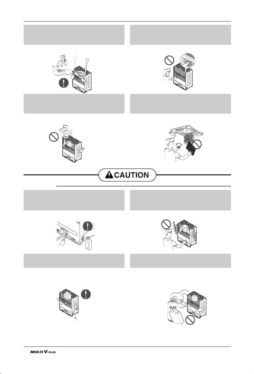
Safety Precautions
Safety Precautions
To prevent injury to the user or other people and property damage, the following instructions must
be followed.
■ Incorrect operation due to ignoring instruction will cause harm or damage. The seriousness is
classified by the following indications.
■ Meanings of symbols used in this manual are as shown below.
This symbol indicates the possibility of death or serious injury.
This symbol indicates the possibility of injury or damage to properties only.
Be sure not to do.
Be sure to follow the instruction.
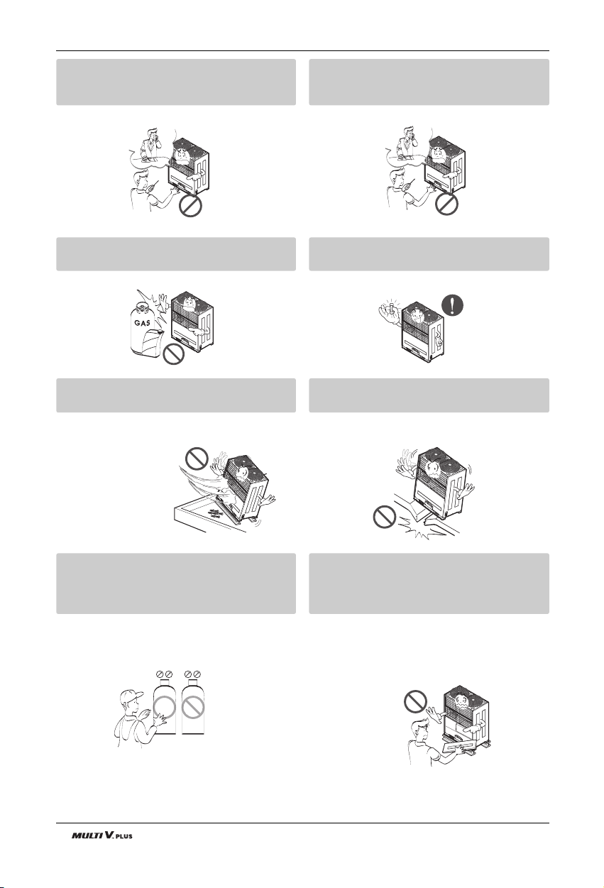
■ Installation
Have all electric work done by a licensed
electrician according to "Electric Facility
Engineering Standard" and "Interior Wire
Regulations" and the instructions given in
this manual and always use a special circuit.
• If the power source capacity is inadequate or
electric work is performed improperly, electric
shock or fire may result.
Ask the dealer or an authorized technician to
install the air conditioner.
• Improper installation by the user may result in
water leakage, electric shock, or fire.
Always ground the product.
• There is risk of fire or electric shock.
Always intstall a dedicated circuit and breaker.
• Improper wiring or installation may cause fire or
electric shock.
4 Outdoor Unit
Safety Precautions
For re-installation of the installed product,
always contact a dealer or an Authorized
Service Center.
• There is risk of fire, electric shock, explosion, or
injury.
Do not install, remove, or re-install the unit
by yourself (customer).
• There is risk of fire, electric shock, explosion, or
injury.
Do not store or use flammable gas or
combustibles near the air conditioner.
• There is risk of fire or failure of product.
Use the correctly rated breaker or fuse.
•Thereisriskoffireorelectricshock.
Prepare for strong wind or earthquake and
install the unit at the specified place.
• Improper installation may cause the unit to topple and result in injury.
Do not install the product on a defective
installation stand.
• It may cause injury, accident, or damage to the
product.
When installing and moving the air conditioner to another site, do not charge it with a
different refrigerant from the refrigerant
specified on the unit.
• If a different refrigerant or air is mixed with the
original refrigerant, the refrigerant cycle may
malfunction and the unit may be damaged.
Do not reconstruct to change the settings of
the protection devices.
• If the pressure switch, thermal switch, or other
protection device is shorted and operated
forcibly, or parts other than those specified by
LGE are used, fire or explosion may result.
Gasolin
R22
R410A
R407C

Installation Manual 5
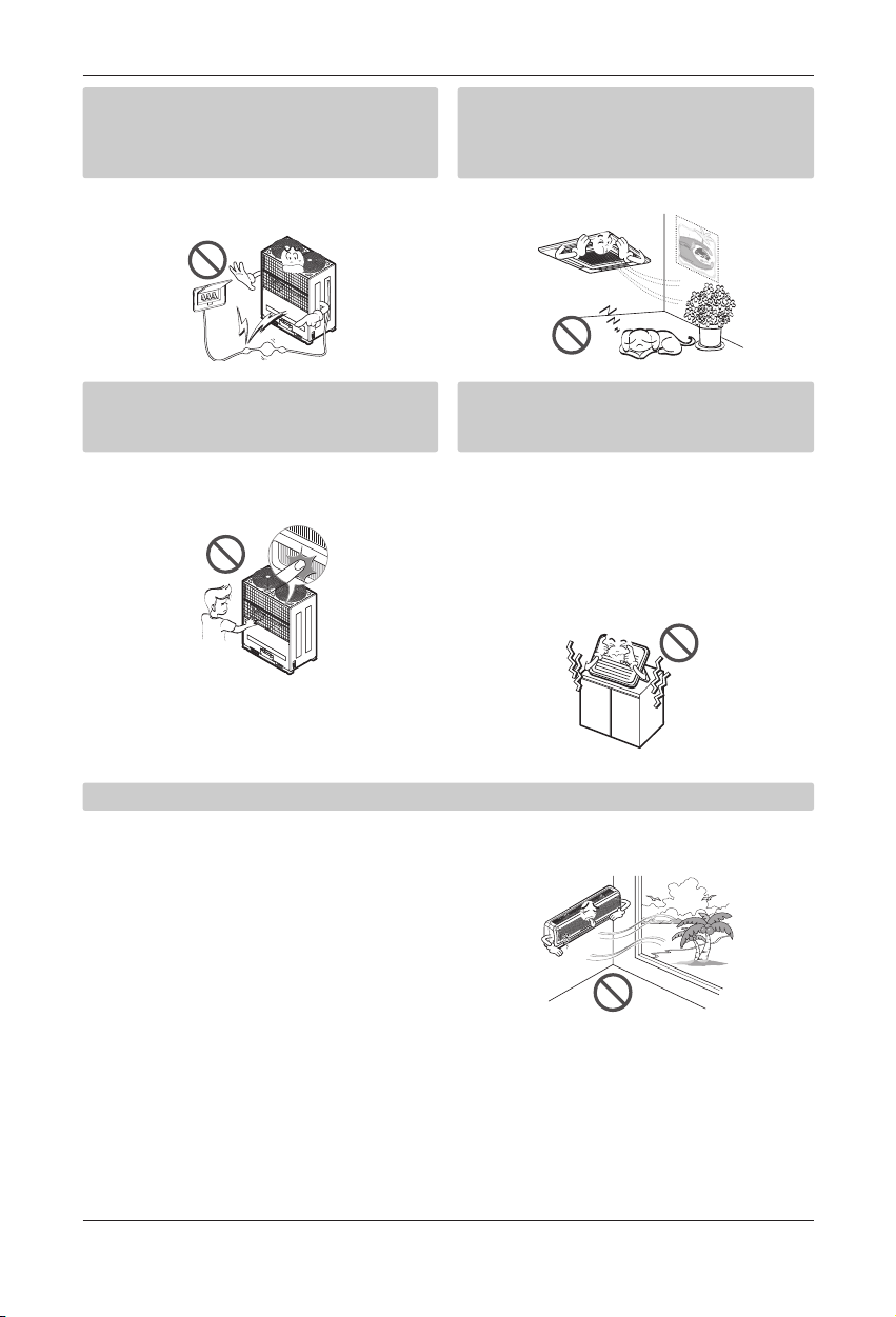
Safety Precautions
Ventilate before operating air conditioner
when gas leaked out.
• It may cause explosion, fire, and burn.
Securely install the cover of control box and
the panel.
• If the cover and panel are not installed securely,
dust or water may enter the outdoor unit and fire
or electric shock may result.
If the air conditioner is installed in a small room, measures must be taken to prevent the
refrigerant concentration from exceeding the safety limit when the refrigerant leaks.
• Consult the dealer regarding the appropriate measures to prevent the safety limit from being exceeded. Should the refrigerant leak and cause the safety limit to be exceeded, harzards due to lack of oxygen in the room could result.
■ Operation
Do not damage or use an unspecified power
cord.
• There is risk of fire, electric shock, explosion, or
injury.
Use a dedicated outlet for this appliance.
• There is risk of fire or electrical shock.
Be cautious that water could not enter the
product.
• There is risk of fire, electric shock, or product
damage.
Do not touch the power switch with wet
hands.
• There is risk of fire, electric shock, explosion, or
injury.
6 Outdoor Unit
Safety Precautions
When the product is soaked (flooded or
submerged), contact an Authorized Service
Center.
• There is risk of fire or electric shock.
Be cautious not to touch the sharp edges
when installing.
• It may cause injury.
Take care to ensure that nobody could step
on or fall onto the outdoor unit.
• This could result in personal injury and product
damage.
Do not open the inlet grill of the product during operation. (Do not touch the electrostatic
filter, if the unit is so equipped.)
• There is risk of physical injury, electric shock, or
product failure.
■ Installation
Always check for gas (refrigerant) leakage
after installation or repair of product.
• Low refrigerant levels may cause failure of
product.
Do not install the product where the noise or
hot air from the outdoor unit could damage
the neighborhoods.
• It may cause a problem for your neighbors.
Keep level even when installing the product.
• To avoid vibration or water leakage.
Do not install the unit where combustible gas
may leak.
• If the gas leaks and accumulates around the
unit, an explosion may result.
90˚
Gasolin
Installation Manual 7
Safety Precautions
Use power cables of sufficient current
carrying capacity and rating.
• Cables that are too small may leak, generate
heat, and cause a fire.
Do not use the product for special purposes,
such as preserving foods, works of art, etc. It
is a consumer air conditioner, not a precision
refrigeration system.
• There is risk of damage or loss of property.
Keep the unit away from children. The heat
exchanger is very sharp.
• It can cause the injury, such as cutting the finger.
Also the damaged fin may result in degradation
of capacity.
When installting the unit in a hospital, communication station, or similar place, provide
sufficient protection against noise.
•
The inverter equipment, private power generator,
high-frequency medical equipment, or radio communication equipment may cause the air conditioner to operate erroneously, or fail to operate. On the
other hand, the air conditioner may affect such
equipment by creating noise that disturbs medical
treatment or image broadcasting.
Do not install the product where it is exposed to sea wind (salt spray) directly.
• It may cause corrosion on the product. Corrosion, particularly on the condenser and evaporator fins,
could cause product malfunction or inefficient operation.

8 Outdoor Unit
Safety Precautions
■ Operation
Do not use the air conditioner in special
environments.
• Oil, steam, sulfuric smoke, etc. can significantly
reduce the performance of the air conditioner or
damage its parts.
Do not block the inlet or outlet.
• It may cause failure of appliance or accident.
Make the connections securely so that the
outside force of the cablemay not be applied
to the terminals.
• Inadequate connection and fastening may generate heat and cause a fire.
Be sure the installation area does not deteriorate with age.
• If the base collapses, the air conditioner could
fall with it, causing property damage, product
failure, or personal injury.
Install and insulate the drain hose to ensure that water is drained away properly based on the
installation manual.
• A bad connection may cause water leakage.
Be very careful about product transportation.
• Only one person should not carry the product if it weighs more
than 20 kg.
• Some products use PP bands for packaging. Do not use any PP
bands for a means of transportation. It is dangerous.
• Do not touch the heat exchanger fins. Doing so may cut your
fingers.
• When transporting the Outdoor Unit, suspending it at the specified
positions on the unit base. Also support the Outdoor Unit at four
points so that it cannot slip sideways.
Installation Manual 9
Safety Precautions
Safely dispose of the packing materials.
•
Packing materials, such as nails and other metal or
wooden parts, may cause stabs or other injuries.
•
Tear apart and throw away plastic packaging bags
so that children may not play with them. If children
play with a plastic bag which was
not torn apart, they face the
risk of suffocation.
Turn on the power at least 6 hours before
starting operation.
• Starting operation immediately after turning on
themainpowerswitchcanresultinsevere
damage to internal parts. Keep the power switch
turned on during the operational season.
Do not touch any of the refrigerant piping
during and after operation.
• It can cause a burn or frostbite.
Do not operate the air conditioner with the
panels or guards removed.
• Rotating, hot, or high-voltage parts can cause
injuries.
Do not directly turn off the main power
switch after stopping operation.
• Wait at least 5 minutes before turning off the
main power switch.
Otherwise it may result in
waterleakageorother
problems.
Auto-addressing should be done in condition of
connecting the power of all indoor and outdoour
units. Auto-addressing should also be done in
case of changing the Indoor Unit board(PCB).
Use a firm stool or ladder when cleaning or
maintaining the air conditioner.
• Be careful and avoid personal injury.
Do not insert hands or other objects through
the air inlet or outlet while the air conditioner
is plugged in.
• There are sharp and moving parts that could
cause personal injury.
10 Outdoor Unit
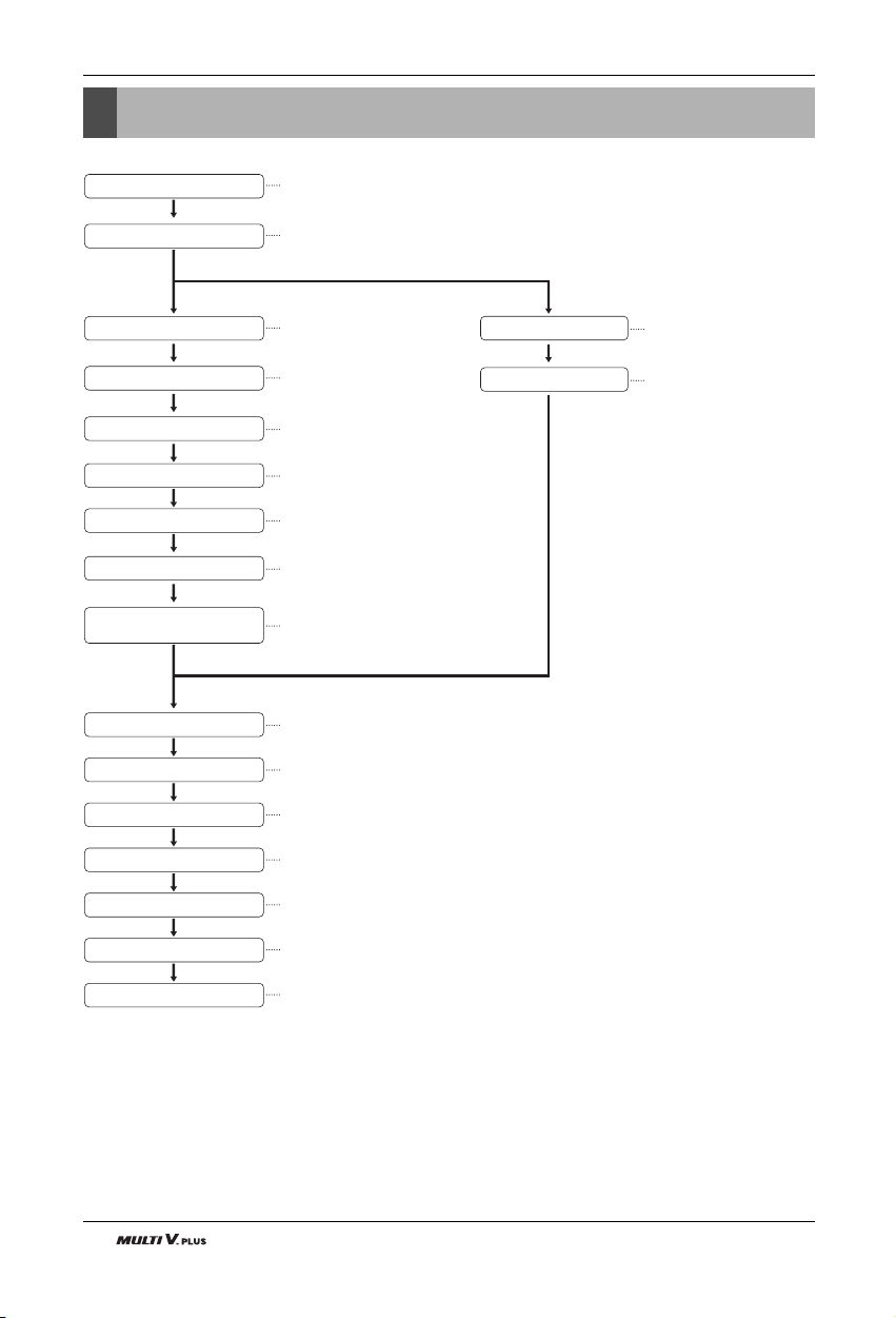
Installation
Installation Process
The foundation must be level
Outdoor unit foundation work
Avoid short circuits and ensure
sufficient space is allowed for service
Installation of outdoor unit
Refer to automatic addressing flowchart
Preheat the crank case with the electrical heater for more than 6 hours.
Automatic addressing of indoor unit
In the final check for 24hours at 2.94 MPa(30.0 kg/cm
2
) there must be no drop in pressure.
All tight test
Multiple core cable must not be used.
(suitable cable should be selected)
Electrical work
(connection circuits and drive circuits)
Make sure no gaps are left where
the insulating materials are joined
Heat insulation work
Make sure airflow is sufficient
Duct work
Adjust to downward gradient
Drain pipe work
Special attention to dryness,
cleanness and tightness
Refrigerant piping work
Check model name to make
sure the fitting is made correctly
Installation of indoor unit
Take account of gradient
of drain piping
Sleeve and insert work
Make relationship between outdoor, indoor, remote controller, And option connections clear.
(Prepare control circuit diagram)
Preparation of contract drawings
Indicate clearly who is to be responsible for switch settings
Determination of division work
The vacuum pump used must have a capacity of reaching at least 5 torr, more than 1 hour
Vacuum drying
Recharge correctly as calculated in this manual. and record the amount of additive refrigerant
Additional charge of refrigerant
Make sure there are no gaps left between the facing materials used on the ceiling
Fit facing panels
Run each indoor unit in turn to make sure the pipe work has been fitted correctly
Test run adjustment
Explain the use of the system as clearly as possible to your customer and make sure all relevant documentation is in order
Transfer to customer with explanation
The above list indicates the order in which the individual work operations are normally carried out but this order
may be varied where local conditions warrants such change.
Installation Manual 11
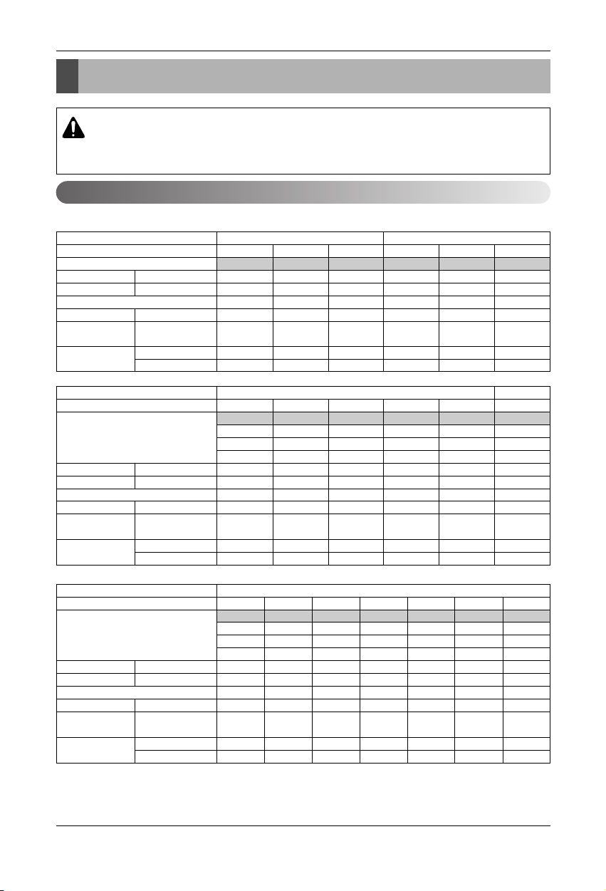
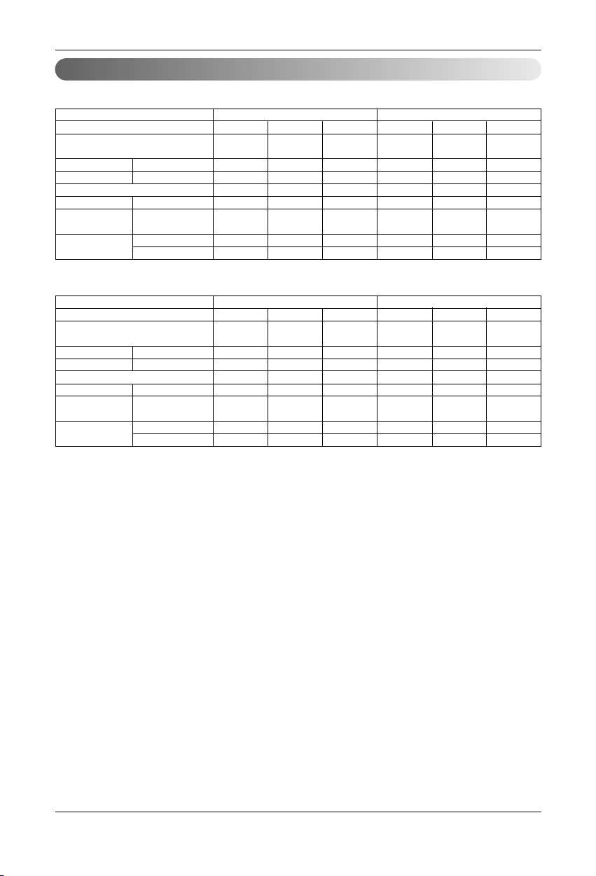
Outdoor Units Information
Outdoor Units Information
CAUTION: A ratio of the running Indoor Units with the Outdoor: Within 10 ~ 100%
A ratio of the connectable Indoor Units with the Outdoor Unit : within 50 ~ 130%
130% combination ratio is a reduction in capacity in defrost
Power Supply: Outdoor Unit (3Ø, 380 ~ 415V, 50Hz)
■ Cooling Only
Unit
System(HP)
Model
Product Charge kg
CF(Correction Factor) kg
Max. Connectable No. of Indoor Units
Net Weight kg(lbs)
Dimensions (W x H x D)
mm(inch)
Pipe Connections
Liquid Pipes(mm(inch))
Gas Pipes(mm(inch))
1 Outdoor Unit(Half size) 1 Outdoor Unit
568101214
LRUV508T1 LRUV608T1 LRUV808T1S LRUV1008T1 LRUV1208T1 LRUV1408T1
44.5 6 101010
00 0-2-1-1
6 8 13 16 20 20
150(330.7) 150(330.7) 150(330.7) 300(661.4) 300(661.4) 300(661.4)
806 x 1607 x 730 806 x 1607 x 730 806 x 1607 x 730 1280 x 1607 x 730 1280 x 1607 x 730 1280 x 1607 x 730
(31.7 x 63.3 x 28.7) (31.7 x 63.3 x 28.7) (31.7 x 63.3 x 28.7) (50.4 x 63.3 x 28.7) (50.4 x 63.3 x 28.7) (50.4 x 63.3 x 28.7)
Ø9.52(3/8) Ø9.52(3/8) Ø12.7(1/2) Ø12.7(1/2) Ø12.7(1/2) Ø12.7(1/2)
Ø19.05(3/4) Ø22.2(7/8) Ø28.58(1
1
/8) Ø28.58(11/8) Ø28.58(11/8) Ø28.58(11/8)
Unit
System(HP)
Model
Product Charge kg
CF(Correction Factor) kg
Max. Connectable No. of Indoor Units
Net Weight kg(lbs)
Dimensions (W x H x D)
mm(inch)
Pipe Connections
Liquid Pipes(mm(inch))
Gas Pipes(mm(inch))
2 Outdoor Units
3 Outdoor Units
16 18 20 22 24 26
LRUV1608T1 LRUV1808T1 LRUV2008T1 LRUV2208T1 LRUV2408T1 LRUV2608T1
LRUV808T1 LRUV1008T1 LRUV1008T1 LRUV1208T1 LRUV1208T1 LRUV1008T1
LRUC808T1 LRUC808T1 LRUC1008T1 LRUC1008T1 LRUC1208T1 LRUC808T1
LRUC808T1
10x2 10x2 10x2 10x2 10x2 10x3
-2 -2 -2 -2 -2 0
20 20 20 22 24 32
300(661.4) x 2 300(661.4) x 2 300(661.4) x 2 300(661.4) x 2 300(661.4) x 2 300(661.4) x 3
(1280 x 1607 x 730) x 2 (1280 x 1607 x 730) x 2 (1280 x 1607 x 730) x 2 (1280 x 1607 x 730) x 2 (1280 x 1607 x 730) x 2 (1280 x 1607 x 730) x 3
((50.4 x 63.3 x 28.7) x 2) ((50.4 x 63.3 x 28.7) x 2) ((50.4 x 63.3 x 28.7) x 2) ((50.4 x 63.3 x 28.7) x 2) ((50.4 x 63.3 x 28.7) x 2) ((50.4 x 63.3 x 28.7) x 3)
Ø19.05(3/4) Ø19.05(3/4) Ø19.05(3/4) Ø19.05(3/4) Ø19.05(3/4) Ø22.2(7/8)
Ø38.1(1
1
/2) Ø38.1(11/2) Ø38.1(11/2) Ø38.1(11/2) Ø38.1(11/2) Ø44.5(13/4)
Unit
System(HP)
Model
Product Charge kg
CF(Correction Factor) kg
Max. Connectable No. of Indoor Units
Net Weight kg(lbs)
Dimensions (W x H x D)
mm(inch)
Pipe Connections
Liquid Pipes(mm(inch))
Gas Pipes(mm(inch))
3 Outdoor Units
28 30 32 34 36 38 40
LRUV2808T1 LRUV3008T1 LRUV3208T1 LRUV3408T1 LRUV3608T1 LRUV3808T1 LRUV4008T1
LRUV1008T1 LRUV1008T1 LRUV1208T1 LRUV1208T1 LRUV1208T1 LRUV1408T1 LRUV1408T1
LRUC1008T1 LRUC1008T1 LRUC1008T1 LRUC1208T1 LRUC1208T1 LRUC1208T1 LRUC1408T1
LRUC808T1 LRUC1008T1 LRUC1008T1 LRUC1008T1 LRUC1208T1 LRUC1208T1 LRUC1208T1
10 x 3 10 x 3 10 x 3 10 x 3 10 x 3 10 x 3 10 x 3
0001122
32 32 32 34 36 38 40
300(661.4) x 3 300(661.4) x 3 300(661.4) x 3 300(661.4) x 3 300(661.4) x 3 300(661.4) x 3 300(661.4) x 3
(1280 x 1607 x 730) x 3 (1280 x 1607 x 730) x 3 (1280 x 1607 x 730) x 3 (1280 x 1607 x 730) x 3 (1280 x 1607 x 730) x 3 (1280 x 1607 x 730) x 3 (1280 x 1607 x 730) x 3
((50.4 x 63.3 x 28.7) x 3) ((50.4 x 63.3 x 28.7) x 3) ((50.4 x 63.3 x 28.7) x 3) ((50.4 x 63.3 x 28.7) x 3) ((50.4 x 63.3 x 28.7) x 3) ((50.4 x 63.3 x 28.7) x 3) ((50.4 x 63.3 x 28.7) x 3)
Ø22.2(7/8) Ø22.2(7/8) Ø22.2(7/8) Ø22.2(7/8) Ø22.2(7/8) Ø22.2(7/8) Ø22.2(7/8)
Ø44.5(1
3
/4) Ø44.5(13/4) Ø44.5(13/4) Ø44.5(13/4) Ø44.5(13/4) Ø44.5(13/4) Ø44.5(13/4)
12 Outdoor Unit
Outdoor Units Information
■ Heat Pump
Unit
System(HP)
Model
Product Charge kg
CF(Correction Factor) kg
Max. Connectable No. of Indoor Units
Net Weight kg(lbs)
Dimensions (W x H x D)
mm(inch)
Pipe Connections
Liquid Pipes(mm(inch))
Gas Pipes(mm(inch))
1 Outdoor Unit(Half size)
1 Outdoor Unit
568101214
LRUN508T1 LRUN608T1 LRUN808T1 LRUN1008T1 LRUN1208T1 LRUN1408T1
4 4.5 10 10 10 10
0 0 -3 -2 -1 -1
6 8 13 16 20 20
150(330.7) 150(330.7) 300(661.4) 300(661.4) 300(661.4) 300(661.4)
806 x 1607 x 730 806 x 1607 x 730 1280 x 1607 x 730 1280 x 1607 x 730 1280 x 1607 x 730 1280 x 1607 x 730
(
31.7 x 63.3 x 28.7) (31.7 x 63.3 x 28.7) (50.4 x 63.3 x 28.7) (50.4 x 63.3 x 28.7) (50.4 x 63.3 x 28.7) (50.4 x 63.3 x 28.7)
Ø9.52(3/8) Ø9.52(3/8) Ø12.7(1/2) Ø12.7(1/2) Ø12.7(1/2) Ø12.7(1/2)
Ø19.05(3/4) Ø22.2(7/8) Ø28.58(11/8) Ø28.58(11/8) Ø28.58(11/8) Ø28.58(11/8)
Unit
System(HP)
Model
Product Charge kg
CF(Correction Factor) kg
Max. Connectable No. of Indoor Units
Net Weight kg(lbs)
Dimensions (W x H x D)
mm(inch)
Pipe Connections
Liquid Pipes(mm(inch))
Gas Pipes(mm(inch))
2 Outdoor Units
3 Outdoor Units
16 18 20 22 24 26
LRUN1608T1 LRUN1808T1 LRUN2008T1 LRUN2208T1 LRUN2408T1 LRUN2608T1
LRUN808T1 LRUN1008T1 LRUN1008T1 LRUN1208T1 LRUN1208T1 LRUN1008T1
LRUH808T1 LRUH808T1 LRUH1008T1 LRUH1008T1 LRUH1208T1 LRUH808T1
LRUH808T1
10x2 10x2 10x2 10x2 10x2 10x3
-2 -2 -2 -2 -2 0
20 20 20 22 24 32
300(661.4) x 2 300(661.4) x 2 300(661.4) x 2 300(661.4) x 2 300(661.4) x 2 300(661.4) x 3
(1280 x 1607 x 730) x 2 (1280 x 1607 x 730) x 2 (1280 x 1607 x 730) x 2 (1280 x 1607 x 730) x 2 (1280 x 1607 x 730) x 2 (1280 x 1607 x 730) x 3
((50.4 x 63.3 x 28.7) x 2) ((50.4 x 63.3 x 28.7) x 2) ((50.4 x 63.3 x 28.7) x 2) ((50.4 x 63.3 x 28.7) x 2) ((50.4 x 63.3 x 28.7) x 2) ((50.4 x 63.3 x 28.7) x 3)
Ø19.05(3/4) Ø19.05(3/4) Ø19.05(3/4) Ø19.05(3/4) Ø19.05(3/4) Ø22.2(7/8)
Ø38.1(11/2) Ø38.1(11/2) Ø38.1(11/2) Ø38.1(11/2) Ø38.1(11/2) Ø44.5(13/4)
Unit
System(HP)
Model
Product Charge kg
CF(Correction Factor) kg
Max. Connectable No. of Indoor Units
Net Weight kg(lbs)
Dimensions (W x H x D)
mm(inch)
Pipe Connections
Liquid Pipes(mm(inch))
Gas Pipes(mm(inch))
3 Outdoor Units
28 30 32 34 36 38 40
LRUN2808T1 LRUN3008T1 LRUN3208T1 LRUN3408T1 LRUN3608T1 LRUN3808T1 LRUN4008T1
LRUN1008T1 LRUN1008T1 LRUN1208T1 LRUN1208T1 LRUN1208T1 LRUN1408T1 LRUN1408T1
LRUH1008T1 LRUH1008T1 LRUH1008T1 LRUH1208T1 LRUH1208T1 LRUH1208T1 LRUH1408T1
LRUH808T1 LRUH1008T1 LRUH1008T1 LRUH1008T1 LRUH1208T1 LRUH1208T1 LRUH1208T1
10x3 10x3 10x3 10x3 10x3 10x3 10x3
0001122
32 32 32 34 36 38 40
300(661.4) x 3 300(661.4) x 3 300(661.4) x 3 300(661.4) x 3 300(661.4) x 3 300(661.4) x 3 300(661.4) x 3
(1280 x 1607 x 730) x 3 (1280 x 1607 x 730) x 3 (1280 x 1607 x 730) x 3 (1280 x 1607 x 730) x 3 (1280 x 1607 x 730) x 3 (1280 x 1607 x 730) x 3 (1280 x 1607 x 730) x 3
((50.4 x 63.3 x 28.7) x 3) ((50.4 x 63.3 x 28.7) x 3) ((50.4 x 63.3 x 28.7) x 3) ((50.4 x 63.3 x 28.7) x 3) ((50.4 x 63.3 x 28.7) x 3) ((50.4 x 63.3 x 28.7) x 3) ((50.4 x 63.3 x 28.7) x 3)
Ø22.2(7/8) Ø22.2(7/8) Ø22.2(7/8) Ø22.2(7/8) Ø22.2(7/8) Ø22.2(7/8) Ø22.2(7/8)
Ø44.5(13/4) Ø44.5(13/4) Ø44.5(13/4) Ø44.5(13/4) Ø44.5(13/4) Ø44.5(13/4) Ø44.5(13/4)
Installation Manual 13
Outdoor Units Information
Power Supply: Outdoor Unit (3Ø, 380V, 60Hz)
■ Cooling Only
Unit
System(HP)
Model
Product Charge kg
CF(Correction Factor) kg
Max. Connectable No. of Indoor Units
Net Weight kg(lbs)
Dimensions (W x H x D)
mm(inch)
Pipe Connections
Liquid Pipes(mm(inch))
Gas Pipes(mm(inch))
1 Outdoor Unit(Half size) 1 Outdoor Unit
568101214
LRUV509T1 LRUV609T1 LRUV809T1S LRUV1009T1 LRUV1209T1 LRUV1409T1
44.56 101010
000-2-1-1
6 8 13 16 20 20
150(330.7) 150(330.7) 150(330.7) 300(661.4) 300(661.4) 300(661.4)
806 x 1607 x 730 806 x 1607 x 730 806 x 1607 x 730 1280 x 1607 x 730 1280 x 1607 x 730 1280 x 1607 x 730
(31.7 x 63.3 x 28.7) (31.7 x 63.3 x 28.7) (31.7 x 63.3 x 28.7) (50.4 x 63.3 x 28.7) (50.4 x 63.3 x 28.7) (50.4 x 63.3 x 28.7)
Ø9.52(3/8) Ø9.52(3/8) Ø12.7(1/2) Ø12.7(1/2) Ø12.7(1/2) Ø12.7(1/2)
Ø19.05(3/4) Ø22.2(7/8) Ø28.58(1
1
/8) Ø28.58(11/8) Ø28.58(11/8) Ø28.58(11/8)
Unit
System(HP)
Model
Product Charge kg
CF(Correction Factor) kg
Max. Connectable No. of Indoor Units
Net Weight kg(lbs)
Dimensions (W x H x D)
mm(inch)
Pipe Connections
Liquid Pipes(mm(inch))
Gas Pipes(mm(inch))
2 Outdoor Units
16 18 20 22 24 26
LRUV1609T1 LRUV1809T1 LRUV2009T1 LRUV2209T1 LRUV2409T1 LRUV2609T1
LRUV809T1 LRUV1009T1 LRUV1009T1 LRUV1209T1 LRUV1209T1 LRUV1409T1
LRUC809T1 LRUC809T1 LRUC1009T1 LRUC1009T1 LRUC1209T1 LRUC1209T1
10x2 10x2 10x2 10x2 10x2 10x2
-2 -2 -2 -2 -2 -1
20 20 20 22 24 26
300(661.4) x 2 300(661.4) x 2 300(661.4) x 2 300(661.4) x 2 300(661.4) x 2 300(661.4) x 2
(1280 x 1607 x 730) x 2 (1280 x 1607 x 730) x 2 (1280 x 1607 x 730) x 2 (1280 x 1607 x 730) x 2 (1280 x 1607 x 730) x 2 (1280 x 1607 x 730) x 2)
((50.4 x 63.3 x 28.7) x 2) ((50.4 x 63.3 x 28.7) x 2) ((50.4 x 63.3 x 28.7) x 2) ((50.4 x 63.3 x 28.7) x 2) ((50.4 x 63.3 x 28.7) x 2) ((50.4 x 63.3 x 28.7) x 2)
Ø19.05(3/4) Ø19.05(3/4) Ø19.05(3/4) Ø19.05(3/4) Ø19.05(3/4) Ø19.05(3/4)
Ø38.1(1
1
/2) Ø38.1(11/2) Ø38.1(11/2) Ø38.1(11/2) Ø38.1(11/2) Ø38.1(11/2)
Unit
System(HP)
Model
Product Charge kg
CF(Correction Factor) kg
Max. Connectable No. of Indoor Units
Net Weight kg(lbs)
Dimensions (W x H x D)
mm(inch)
Pipe Connections
Liquid Pipes(mm(inch))
Gas Pipes(mm(inch))
3 Outdoor Units
28 30 32 34 36 38 40
LRUV2809T1 LRUV3009T1 LRUV3209T1 LRUV3409T1 LRUV3609T1 LRUV3809T1 LRUV4008T1
LRUV1009T1 LRUV1009T1 LRUV1209T1 LRUV1209T1 LRUV1209T1 LRUV1409T1 LRUV1409T1
LRUC1009T1 LRUC1009T1 LRUC1009T1 LRUC1209T1 LRUC1209T1 LRUC1209T1 LRUC1409T1
LRUC809T1 LRUC1009T1 LRUC1009T1 LRUC1009T1 LRUC1209T1 LRUC1209T1 LRUC1209T1
10 x 3 10 x 3 10 x 3 10 x 3 10 x 3 10 x 3 10 x 3
0001122
32 32 32 34 36 38 40
300(661.4) x 3 300(661.4) x 3 300(661.4) x 3 300(661.4) x 3 300(661.4) x 3 300(661.4) x 3 300(661.4) x 3
(1280 x 1607 x 730) x 3 (1280 x 1607 x 730) x 3 (1280 x 1607 x 730) x 3 (1280 x 1607 x 730) x 3 (1280 x 1607 x 730) x 3 (1280 x 1607 x 730) x 3 (1280 x 1607 x 730) x 3
((50.4 x 63.3 x 28.7) x 3) ((50.4 x 63.3 x 28.7) x 3) ((50.4 x 63.3 x 28.7) x 3) ((50.4 x 63.3 x 28.7) x 3) ((50.4 x 63.3 x 28.7) x 3) ((50.4 x 63.3 x 28.7) x 3) ((50.4 x 63.3 x 28.7) x 3)
Ø22.2(7/8) Ø22.2(7/8) Ø22.2(7/8) Ø22.2(7/8) Ø22.2(7/8) Ø22.2(7/8) Ø22.2(7/8)
Ø
44.5(13/4)Ø44.5(13/4)Ø44.5(13/4)Ø44.5(13/4)Ø44.5(13/4)Ø44.5(13/4)Ø44.5(13/4)
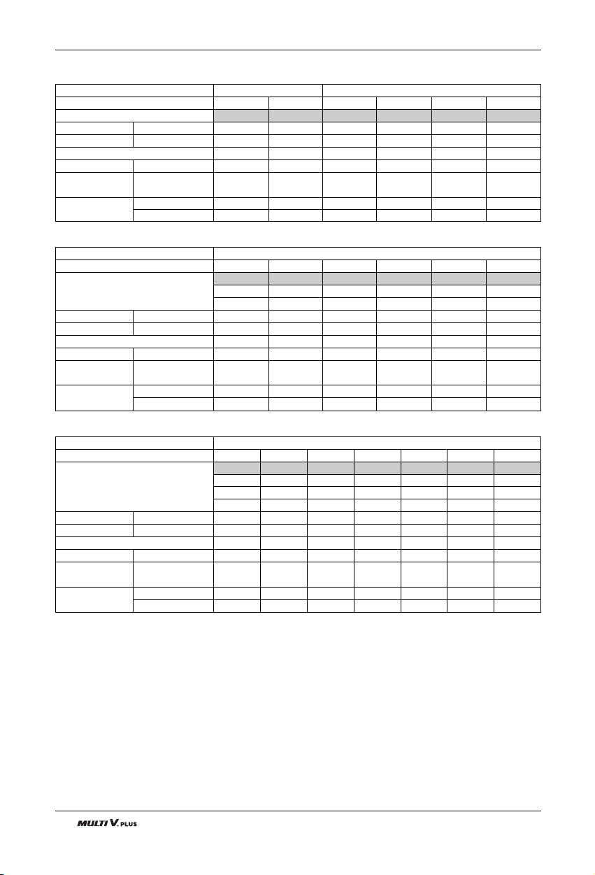
14 Outdoor Unit
Outdoor Units Information
■ Heat Pump
Unit
System(HP)
Model
Product Charge kg
CF(Correction Factor) kg
Max. Connectable No. of Indoor Units
Net Weight kg(lbs)
Dimensions (W x H x D)
mm(inch)
Pipe Connections
Liquid Pipes(mm(inch))
Gas Pipes(mm(inch))
1 Outdoor Unit(Half size)
1 Outdoor Unit
568101214
LRUN509T1 LRUN609T1 LRUN809T1 LRUN1009T1 LRUN1209T1 LRUN1409T1
4 4.5 10 10 10 10
0 0 -3 -2 -1 -1
6 8 13 16 20 20
150(330.7) 150(330.7) 300(661.4) 300(661.4) 300(661.4) 300(661.4)
806 x 1607 x 730 806 x 1607 x 730 1280 x 1607 x 730 1280 x 1607 x 730 1280 x 1607 x 730 1280 x 1607 x 730
(31.7 x 63.3 x 28.7) (31.7 x 63.3 x 28.7) (50.4 x 63.3 x 28.7) (50.4 x 63.3 x 28.7) (50.4 x 63.3 x 28.7) (50.4 x 63.3 x 28.7
Ø9.52(3/8) Ø9.52(3/8) Ø12.7(1/2) Ø12.7(1/2) Ø12.7(1/2) Ø12.7(1/2)
Ø19.05(3/4) Ø22.2(7/8) Ø28.58(1
1
/8) Ø28.58(11/8) Ø28.58(11/8) Ø28.58(11/8)
Unit
System(HP)
Model
Product Charge kg
CF(Correction Factor) kg
Max. Connectable No. of Indoor Units
Net Weight kg(lbs)
Dimensions (W x H x D)
mm(inch)
Pipe Connections
Liquid Pipes(mm(inch))
Gas Pipes(mm(inch))
2 Outdoor Units
16 18 20 22 24 26
LRUN1609T1 LRUN1809T1 LRUN2009T1 LRUN2209T1 LRUN2409T1 LRUN2609T1
LRUN809T1 LRUN1009T1 LRUN1009T1 LRUN1209T1 LRUN1209T1 LRUN1409T1
LRUH809T1 LRUH809T1 LRUH1009T1 LRUH1009T1 LRUH1209T1 LRUH1209T1
10x2 10x2 10x2 10x2 10x2 10x2
-2 -2 -2 -2 -2 -1
20 20 20 22 24 26
300(661.4) x 2 300(661.4) x 2 300(661.4) x 2 300(661.4) x 2 300(661.4) x 2 300(661.4) x 2
(1280 x 1607 x 730) x 2 (1280 x 1607 x 730) x 2 (1280 x 1607 x 730) x 2 (1280 x 1607 x 730)) x 2 (1280 x 1607 x 730) x 2 (1280 x 1607 x 730) x 2
((50.4 x 63.3 x 28.7) x 2) ((50.4 x 63.3 x 28.7) x 2) ((50.4 x 63.3 x 28.7) x 2) ((50.4 x 63.3 x 28.7) x 2) ((50.4 x 63.3 x 28.7) x 2) ((50.4 x 63.3 x 28.7) x 2)
Ø19.05(3/4) Ø19.05(3/4) Ø19.05(3/4) Ø19.05(3/4) Ø19.05(3/4) Ø19.05(3/4)
Ø38.1(1
1
/2) Ø38.1(11/2) Ø38.1(11/2) Ø38.1(11/2) Ø38.1(11/2) Ø38.1(11/2)
Unit
System(HP)
Model
Product Charge kg
CF(Correction Factor) kg
Max. Connectable No. of Indoor Units
Net Weight kg(lbs)
Dimensions (W x H x D)
mm(inch)
Pipe Connections
Liquid Pipes(mm(inch))
Gas Pipes(mm(inch))
3 Outdoor Units
28 30 32 34 36 38 40
LRUN2809T1 LRUN3009T1 LRUN3209T1 LRUN3409T1 LRUN3609T1 LRUN3809T1 LRUN4009T1
LRUN1009T1 LRUN1009T1 LRUN1209T1 LRUN1209T1 LRUN1209T1 LRUN1409T1 LRUN1409T1
LRUH1009T1 LRUH1009T1 LRUH1009T1 LRUH1209T1 LRUH1209T1 LRUH1209T1 LRUH1409T1
LRUH809T1 LRUH1009T1 LRUH1009T1 LRUH1009T1 LRUH1209T1 LRUH1209T1 LRUH1209T1
10x3 10x3 10x3 10x3 10x3 10x3 10x3
0001122
32 32 32 34 36 38 40
300(661.4) x 3 300(661.4) x 3 300(661.4) x 3 300(661.4) x 3 300(661.4) x 3 300(661.4) x 3 300(661.4) x 3
(1280 x 1607 x 730) x 3 (1280 x 1607 x 730) x 3 (1280 x 1607 x 730) x 3 (1280 x 1607 x 730) x 3 (1280 x 1607 x 730) x 3 (1280 x 1607 x 730) x 3 (1280 x 1607 x 730) x 3
((50.4 x 63.3 x 28.7) x 3) ((50.4 x 63.3 x 28.7) x 3) ((50.4 x 63.3 x 28.7) x 3) ((50.4 x 63.3 x 28.7) x 3) ((50.4 x 63.3 x 28.7) x 3) ((50.4 x 63.3 x 28.7) x 3) ((50.4 x 63.3 x 28.7) x 3)
Ø22.2(7/8) Ø22.2(7/8) Ø22.2(7/8) Ø22.2(7/8) Ø22.2(7/8) Ø22.2(7/8) Ø22.2(7/8)
Ø
44.5(13/4)Ø44.5(13/4)Ø44.5(13/4)Ø44.5(13/4)Ø44.5(13/4)Ø44.5(13/4)Ø44.5(13/4)
Installation Manual 15
Outdoor Units Information
Power Supply: Outdoor Unit (3Ø, 220V, 60Hz)
■ Cooling Only
■ Heat Pump
Unit
System(HP)
Model
Product Charge kg
CF(Correction Factor) kg
Max. Connectable No. of Indoor Units
Net Weight kg(lbs)
Dimensions (W x H x D)
mm(inch)
Pipe Connections
Liquid Pipes(mm(inch))
Gas Pipes(mm(inch))
1 Outdoor Unit 2 Outdoor Unit
8 1012161820
LRUV80BT1 LRUV100BT1 LRUV120BT1 LRUV80BT1 LRUV100BT1 LRUV100BT1
LRUC80BT1 LRUC80BT1 LRUC100BT1
10 10 10 20 20 10
-3 -2 -1 -2 -2 -2
13 16 20 20 20 20
300(661.4) 300(661.4) 300(661.4) 300(661.4) x 2 300(661.4) x 2 300(661.4) x 2
1280x1607x730 1280x1607x730 1280x1607x730 (1280x1607x730)x2 (1280x1607x730)x2 (1280x1607x730)x2
(50.4x63.3x28.7) (50.4x63.3x28.7) (50.4x63.3x28.7)
((50.4x63.3x28.7))x2
((50.4x63.3x28.7))x2 ((50.4x63.3x28.7))x2
Ø12.7(1/2) Ø12.7(1/2) Ø12.7(1/2) Ø19.05(3/4) Ø19.05(3/4) Ø19.05(3/4)
Ø28.58(1 1/8) Ø28.58(1 1/8) Ø28.58(1 1/8) Ø38.1(1 1/2) Ø38.1(1 1/2) Ø38.1(1 1/2)
Unit
System(HP)
Model
Product Charge kg
CF(Correction Factor) kg
Max. Connectable No. of Indoor Units
Net Weight kg(lbs)
Dimensions (W x H x D)
mm(inch)
Pipe Connections
Liquid Pipes(mm(inch))
Gas Pipes(mm(inch))
1 Outdoor Unit 2 Outdoor Unit
8 1012161820
LRUN80BT1 LRUN100BT1 LRUN120BT1 LRUN80BT1 LRUN100BT1 LRUN120BT1
LRUH80BT1 LRUH80BT1 LRUH80BT1
10 10 10 20 20 10
-3 -2 -1 -2 -2 -2
13 16 20 20 20 20
300(661.4) 300(661.4) 300(661.4) 300(661.4) x 2 300(661.4) x 2 300(661.4) x 2
1280x1607x730 1280x1607x730 1280x1607x730
(1280x1607x730)x2 (1280x1607x730)x2 (1280x1607x730)x2
(50.4x63.3x28.7) (50.4x63.3x28.7) (50.4x63.3x28.7)
((50.4x63.3x28.7))x2 ((50.4x63.3x28.7))x2 ((50.4x63.3x28.7))x2
Ø12.7(1/2) Ø12.7(1/2) Ø12.7(1/2) Ø19.05(3/4) Ø19.05(3/4) Ø19.05(3/4)
Ø28.58(1 1/8) Ø28.58(1 1/8) Ø28.58(1 1/8) Ø38.1(1 1/2) Ø38.1(1 1/2) Ø38.1(1 1/2)

16 Outdoor Unit
Select the Best Location
Select the Best Location
Select space for installing Outdoor Unit, which will meet the following conditions:
• No direct thermal radiation from other heat sources
• No possibility of annoying the neighbors by noise from unit
• No exposition to strong wind
• With strength which bears weight of unit
• Note that drain flows out of unit when heating
• With space for air passage and service work shown next
• Because of the possibility of fire, do not install unit to the space where generation, inflow, stagnation, and leak
of combustible gas is expected.
• Avoid unit installation in a place where acidic solution and spray (sulfur) are often used.
• Do not use unit under any special environment where oil, steam and sulfuric gas exist.
• It is recommended to fence round the Outdoor Unit in order to prevent any person or animal from accessing
the Outdoor Unit.
• If installation site is area of heavy snowfall, then the following directions should be observed.
- Make the foundation as high as possible.
- Fit a snow protection hood.
• Select installation location considering following conditions to avoid bad condition when additionally performing
defrost operation.
1. Install the outdoor unit at a place well ventilated and having a lot of sunshine in case of installing the product at a place with a high humidity in winter (neare beach, coast, lake, etc).
(Ex) Rooftop where sunshine always shines.
2. Performance of heating will be reduced and preheat time of the indoor unit may be lengthened in case of
installing the outdoor unit in winter at following location:
(1) Shade position with a narrow space
(2) Location with much moisture in neighboring floor.
(3) Location with much humidity around.
(4) Location where ventilation is good.
It is recommended to install the outdoor unit at a place with a lot of sunshine as possible as.
(5) Location where water gathers since the floor is not even.
Installation Manual 17
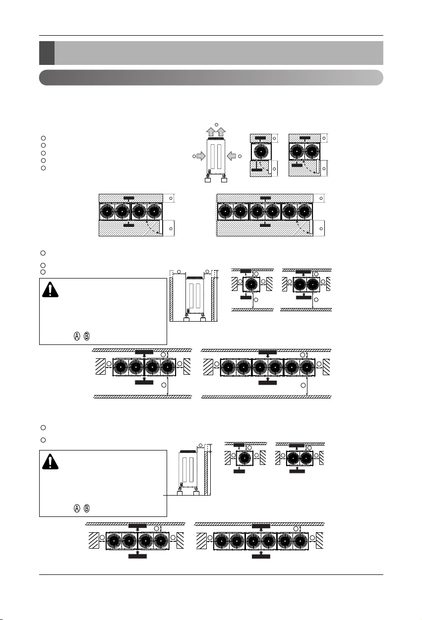
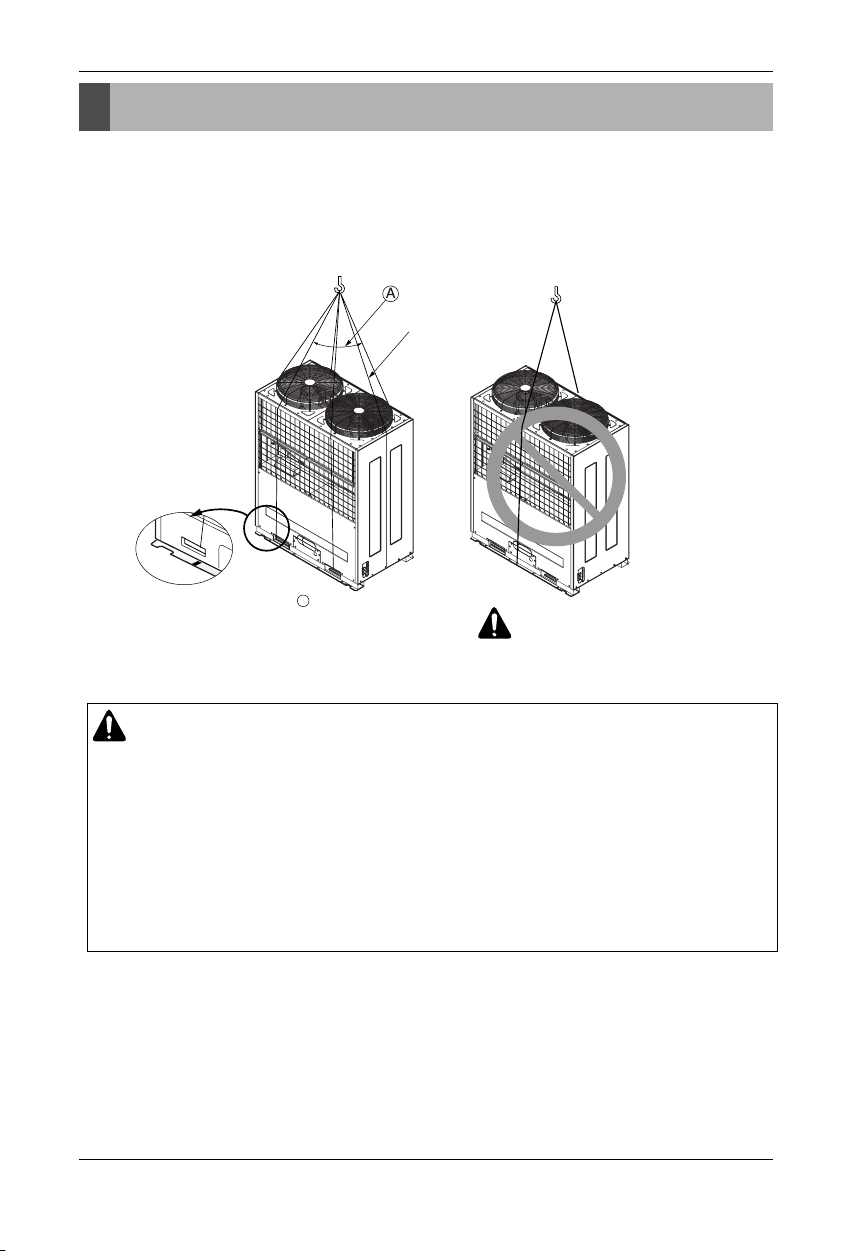
Installation Space
Installation Space
Individual Installation
■ Basic space required
A space of at least 250 mm is necessary at the back for inlet air. Taking servicing, etc. from the rear into
account, a space of about 900 mm should be provided, the same as at the front.
■ When inlet air enters from right and left sides of unit
250 mm or more
900 mm or more (Control box is of a open/close type)
Top discharge (open in principle)
Front inlet (open in principle)
Rear inlet (open in principle)
A
B
C
D
E
A
B
Control Box
Front Side
Rear Side
A
B
Control Box
Front Side
Rear Side
A
B
Control Box
Front Side
Rear Side
A
B
C
900 mm or more
(Control box is of a open/close type)
250 mm or more
150 mm from the wall
C
A
B
C
A
B
h
H
Front Side
Rear Side
C
A
B
C
Front Side
Rear Side
C
A
B
C
Front Side
Rear Side
C
A
B
C
A
B
Control Box
Front Side
Rear Side
Front Side
Rear Side
< Side view > < Top view >
< Side view > < Top view >
C
ED
A
B
250 mm or more
(350mm or more at the coastal area)
150 mm from the wall
B
A
B
A
h
H
Front Side
Rear Side
B
A
B
Front Side
Rear Side
B
A
B
Front Side
Rear Side
B
A
B
Front Side
Rear Side
< Side view > < Top view >
CAUTION
Wall height(H) must not exceed height of
the product. If the wall height is higher
than the whole height of product by (h),
Add (h) to , .
CAUTION
Wall height(H) must not exceed height of
the product. If the wall height is higher
than the whole height of product by (h),
Add (h) to
, .
18 Outdoor Unit
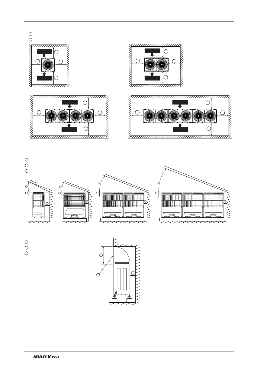
Installation Space
45° or more
200 mm or more
250 mm or more
A
B
C
1000 mm or more
Air outlet guide (Procured at the site)
250 mm or more
D
E
F
< Front view >
< Side view >
E
D
F
A
B
C
A
B
C
A
B
C
A
B
C
■ When unit is surrounded by walls
900 mm or more (Control box is of a open/close type)
250 mm or more
A
B
A
B
B
B
Front Side
Rear Side
A
B
B
B
Front Side
Rear Side
A
B
B
B
Front Side
Rear Side
Front Side
Rear Side
A
B
B
B
■ When there is an obstruction above the unit
Installation Manual 19
Installation Space
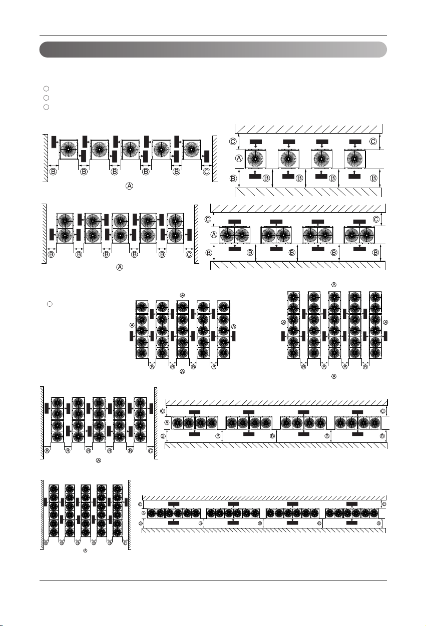
Collective / Continuous installation
Space required for collective installation and continuous installation:When installing several units, leave
the space between each block as shown below considering passage for air and people.
(Be opened)
900mm or more (control box is of a open/close type)
250 mm or more
A
B
= 1250mm or more at the
coastal area
B
C
Front Side
Rear Side
Rear Side
Front Side
Rear Side
Front Side
Rear Side
Front Side
Rear Side
Front Side
Rear Side
Front Side
Rear Side
Front Side
Rear Side
Front Side
Rear Side
Front Side
Rear Side
Front Side
Rear Side
Front Side
Rear Side
Front Side
Rear Side
Front Side
Rear Side
Front Side
Rear Side
Front Side
Rear Side
Front Side
Rear Side
Front Side
Front Side
Rear Side
Front Side
Rear Side
Front Side
Rear Side
Front Side
Rear Side
Front Side
Rear Side
Front Side
Rear Side
Front Side
Rear Side
Front Side
Rear Side
Front Side
Rear Side
Front Side
Rear Side
Front Side
Rear Side
Front Side
Rear Side
Front Side
Rear Side
Front Side
Rear Side
Front Side
Rear Side
Front Side
Rear Side
Front Side
Rear Side
Front Side
Rear Side
Front Side
Rear Side
Front Side
Rear Side
Front Side
Rear Side
Front Side
Rear Side
Front Side
Rear Side
Front Side
Rear Side
Front Side
Rear Side
Front Side
Rear Side
Front Side
Rear Side
Front Side
Rear Side
Front Side
Rear Side
❈
20 Outdoor Unit
Seasonal wind and cautions in winter
• Sufficient measures are required at a snow area or severe cold area in winter so that product can be operated
well.
• Get ready for seasonal wind or snow in winter even in other area.
• Install a suction and discharge duct not to let in snow or rain when the product operates at outdoor temperature
of less than 10°C.
• Install the outdoor unit not to come in contact with snow directly. If snow piles up and freezes on the air suction
hole, the system may malfunction. If it is installed at snowy area, attach the hood to the system.
• Install the outdoor unit at the higher installation console by 50cm than the average snowfall (annual average
snowfall) if it is installed at the area with much snowfall.
• Where snow accumulated on the upper part of the Outdoor Unit by more than 10cm, always remove snow for
operation.
1. The height of H frame must be more than 2 times the snowfall and its width shall not exceed the width of the
product. (If width of the frame is wider than that of the product, snow may accumulate)
2. Don't install the suction hole and discharge hole of the Outdoor Unit facing to the seasonal wind.
CAUTION
• Always apply main power of the outdoor unit during use of product
(cooling season/heating season).
• Always apply power before 6 hours to heat the crank case heater where performing test run after installation of product or where operating the product after cutting the main power of the outdoor unit (for
example, power failure). It may result in burning out of the compressor if not preheating the crank case
with the electrical heater for more than 6 hours. (In case of the outdoor temperature below 10°C)
Lifting Method
Installation Manual 21
Lifting Method
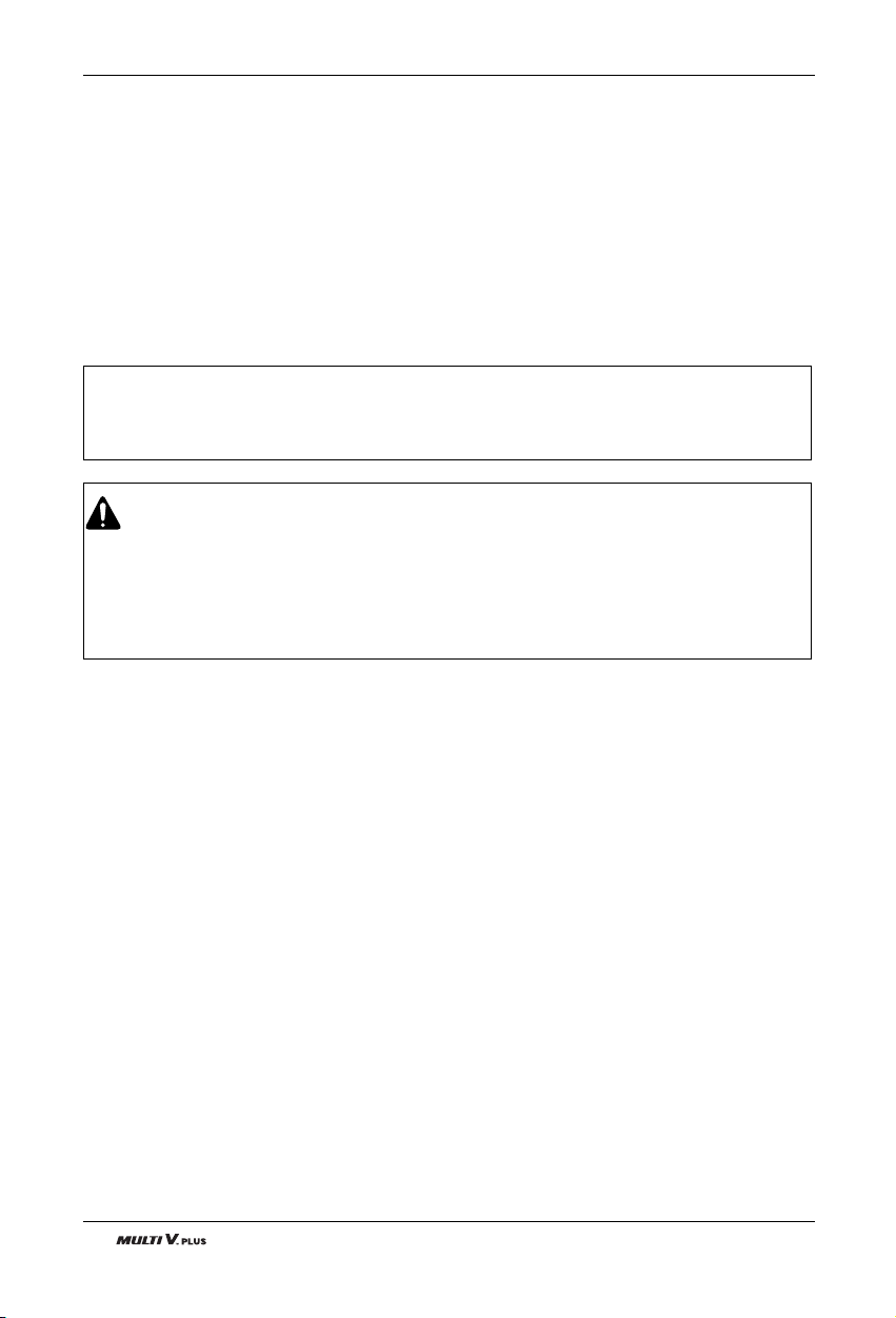
• When carrying the unit suspended, pass the ropes under the unit and use the two suspension points each at
the front and rear.
• Always lift the unit with ropes attached at four points so that impact is not applied to the unit.
• Attach the ropes to the unit at an angle of 40° or less.
Lifting method
CAUTION
Be very careful while carrying the product.
• Do not have only one person carry product if it is more than 20 kg.
• PP bands are used to pack some products. Do not use them as a mean for transportation because they
are dangerous.
• Do not touch heat exchanger fins with your bare hands. Otherwise you may get a cut in your hands.
• Tear plastic packaging bag and scrap it so that children cannot play with it. Otherwise plastic packaging
bag may suffocate children to death.
• When carrying in Outdoor Unit, be sure to support it at four points. Carrying in and lifting with 3-point
support may make Outdoor Unit unstable, resulting in a fall of it.
Sub line
A
40° or less
WARNING
22 Outdoor Unit
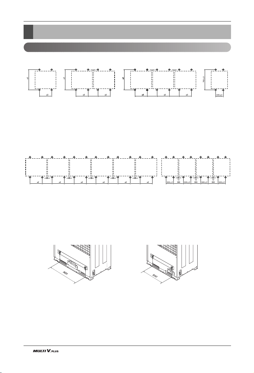
Installation
Location of anchor bolt
Installation
■ Individual installation
■ Example of collective installation
■ Installation foot (Location of anchor bolt)
700
10
900
383
900
700
900
700
900
700
900
10
383
900
10
383
900
900
10
383
900
383
900
10
383
900
10
383
900
10
383
900
10
Half size
Installation Manual 23
Installation
Foundation for Installation
• Fix the unit tightly with bolts as shown below so that unit will not fall down due to earthquake or gust.
• Use the H-beam support as a base support
• Noise and vibration may occur from the floor or wall since vibration is transferred through the installation
part depending on installation status. Thus, use anti-vibration materials (cushion pad) fully (The base pad
shall be more than 200mm).
A
B
D
E
F
G
C
Ensure that the corner part can be securely mounted. Otherwise, the support for
installation may be bent.
Obtain and use the M10 anchor bolt.
The corner was not properly mounted.
Outdoor unit (Insert the cushion pad between outdoor unit and base support to ensure that
anti-vibration may be done in a wide area)
Pipe and wiring space (in case of piping and wiring on the floor surface)
H-Beam support
Concrete base support
G
WAR NING
• Be sure to install unit in a place strong enough to withstand its weight.
Any lack of strength may cause unit to fall down, resulting in a personal injury.
• Have installation work in order to protect against a strong wind and earthquake. Any installation
deficiency may cause unit to fall down, resulting in a personal injury.
• Especially take care for support strength of the floor surface, water drain processing (processing of
water flown out from the Outdoor Unit during operation) and paths of the pipe and wiring when
making a base support.
• Don't use a tube or pipe for water drain in the base pan and perform water drain processing by
using the drain path. Water drain may not be done due to freezing of a tube or pipe.
Rear view Side view
Water
Drain
Path
24 Outdoor Unit
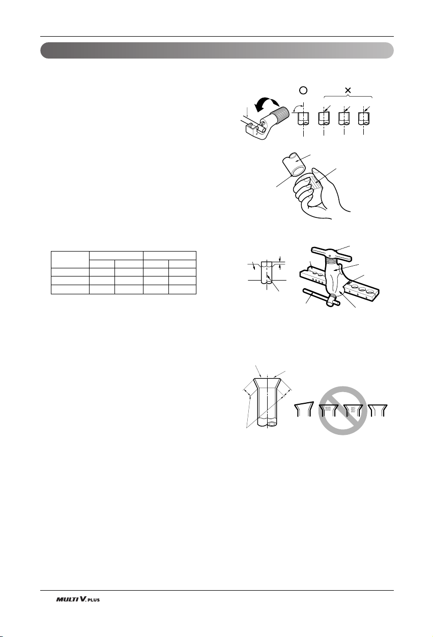
Appendix
Preparation of Piping
1) Cut the pipes and the cable.
■ Use the accessory piping kit or the pipes purchased
locally.
■ Measure the distance between the indoor and the
Outdoor Unit.
■ Cut the pipes a little longer than measured distance.
■ Cut the cable 1.5m longer than the pipe length.
2) Burrs removal
■ Completely remove all burrs from the cut cross section
of pipe/tube.
■ Put the end of the copper tube/pipe to downward direction as you remove burrs in order to avoid to let burrs
drop in the tubing.
3) Flaring work
■ Carry out flaring work using flaring tool as shown below.
Exception)
Wide Art Cool(4.0kW(13,600 Btu/h): Gas pipe(5/8"),
Liquid pipe(3/8")
Firmly hold copper tube in a bar(or die) as indicated
dimension in the table above.
4) Check
■ Compare the flared work with figure below.
■ If flare is noted to be defective, cut off the flared section
and do flaring work again.
Main cause of gas leakage is defect in flaring work. Carry out correct flaring work in the following procedure.
Pipe " A " (mm)
Gas Liquid Gas
Liquid
~4.0(13,600) 1/2" 1/4" 1.6~1.8 1.1~1.3
~9.0(30,700) 5/8" 3/8" 1.6~1.8 1.5~1.7
~15.0(51,200) 3/4" 3/8" 1.9~2.1 1.5~1.7
Indoor Unit
[kW(Btu/h]
Copper
tube
90°
Slanted Uneven Rough
Pipe
Reamer
Point down
Bar
Copper pipe
Clamp handle
Red arrow mark
Cone
Yoke
Handle
Bar
"A"
Inclined
Inside is shining without scratches.
Smooth all round
Even length
all round
Surface
damaged
Cracked Uneven
thickness
= Improper flaring =
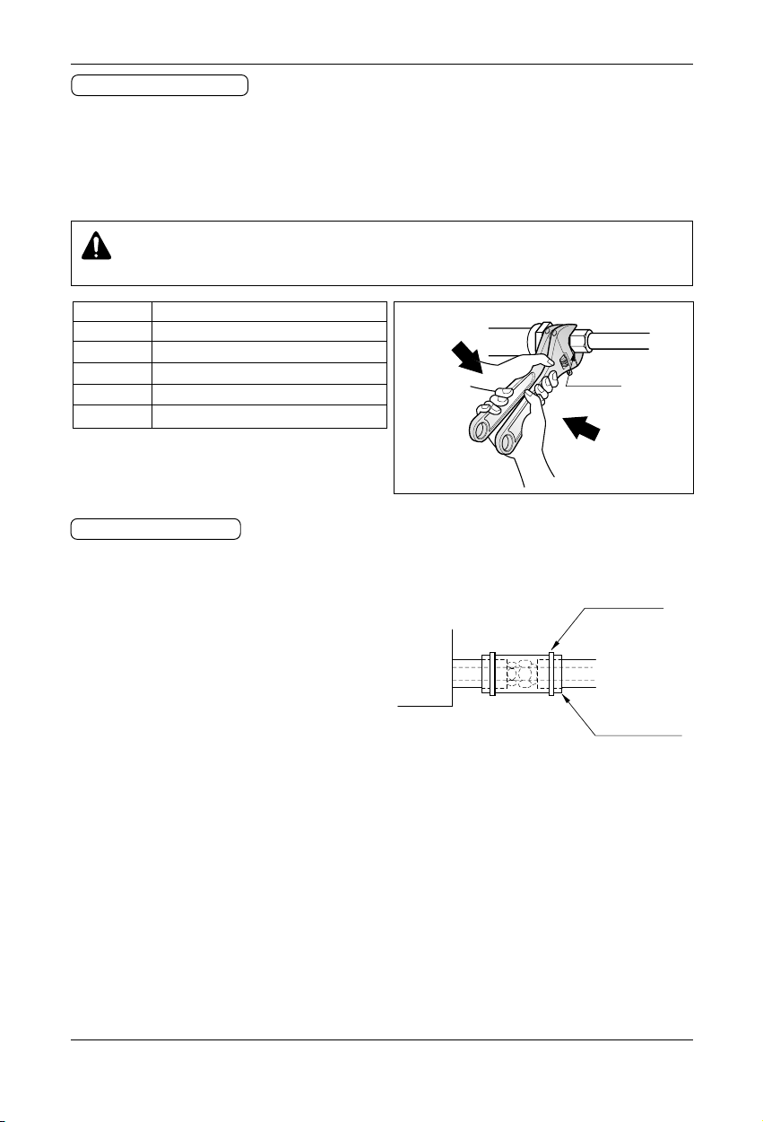
Installation Manual 25
Appendix
1. Form the piping according to its routing. Avoid bending and bending back the same piping point more than
three times. (This will result in hardening the pipe.)
2. After deforming the piping, align centers of the union fitting of the Indoor Unit and the piping, and tighten
them firmly with wrenches.
3. Connect pipe to the service valve or ball valve which is located below the Outdoor Unit.
4. After completing the piping connection, be sure to check if there is gas leakage in indoor and outdoor connection.
Union
Pipe size Flare nut fastening torque (N.m)
Ø6.35mm 18~25
Ø9.52mm 34~42
Ø12.7mm 55~66
Ø15.88mm 63~82
Ø19.05mm 99~121
Piping Connection
CAUTION
Use two wrenches and tighten with regular torque.
1. Use the heat insulation material for the refrigerant piping which has an excellent heat-resistance (over
120°C).
2. Precautions in high humidity circumstance:
This air conditioner has been tested according to the
"ISO Conditions with Mist" and confirmed that there is
not any default. However, if it is operated for a long
time in high humid atmosphere (dew point temperature: more than 23°C), water drops are liable to fall. In
this case, add heat insulation material according to
the following procedure:
• Heat insulation material to be prepared... EPDM
(Ethylene Propylene Diene Methylene)-over 120°C
the heat-resistance temperature.
• Add the insulation over 10mm thickness at high humidity environment.
Indoor Unit
Thermal insulator
(accessory)
Fastening band
(accessory)
Refrigerant piping
HEAT INSULATION
 Loading...