

Page 1

System
Outdoor Unit
INSTALLATION MANUAL
LG
MODELS: LRUV Series
LRUN Series
website http://www.lgservice.com
IMPORTANT
• Please read this installation manual completely before
installing the product.
• Installation work must be performed in accordance with
the national wiring standards by authorized personnel
only.
• Please retain this installation manual for future reference
after reading it thoroughly.
Page 2
2 Outdoor Unit
LRUV(N) Series Outdoor Unit Installation Manual
TABLE OF CONTENTS
Safety Precautions.........................3
Installation Process.....................10
Outdoor Units Information..........11
Select the Best Location.............16
Installation Space ........................17
Lifting method..............................21
Installation....................................22
Refrigerant piping installation....26
Electrical Wiring...........................55
Test Run........................................79
Caution For Refrigerant Leak .....87
Page 3

Installation Manual 3
Safety Precautions
Safety Precautions
To prevent injury to the user or other people and property damage, the following instructions must
be followed.
■ Incorrect operation due to ignoring instruction will cause harm or damage. The seriousness is
classified by the following indications.
■ Meanings of symbols used in this manual are as shown below.
This symbol indicates the possibility of death or serious injury.
This symbol indicates the possibility of injury or damage to properties only.
Be sure not to do.
Be sure to follow the instruction.
■ Installation
Have all electric work done by a licensed
electrician according to "Electric Facility
Engineering Standard" and "Interior Wire
Regulations" and the instructions given in
this manual and always use a special circuit.
• If the power source capacity is inadequate or
electric work is performed improperly, electric
shock or fire may result.
Ask the dealer or an authorized technician to
install the air conditioner.
• Improper installation by the user may result in
water leakage, electric shock, or fire.
Always ground the product.
• There is risk of fire or electric shock.
Always intstall a dedicated circuit and breaker.
• Improper wiring or installation may cause fire or
electric shock.
Page 4

4 Outdoor Unit
Safety Precautions
For re-installation of the installed product,
always contact a dealer or an Authorized
Service Center.
• There is risk of fire, electric shock, explosion, or
injury.
Do not install, remove, or re-install the unit
by yourself (customer).
• There is risk of fire, electric shock, explosion, or
injury.
Do not store or use flammable gas or
combustibles near the air conditioner.
• There is risk of fire or failure of product.
Use the correctly rated breaker or fuse.
• There is risk of fire or electric shock.
Prepare for strong wind or earthquake and
install the unit at the specified place.
• Improper installation may cause the unit to topple and result in injury.
Do not install the product on a defective
installation stand.
• It may cause injury, accident, or damage to the
product.
When installing and moving the air conditioner to another site, do not charge it with a
different refrigerant from the refrigerant
specified on the unit.
• If a different refrigerant or air is mixed with the
original refrigerant, the refrigerant cycle may
malfunction and the unit may be damaged.
Do not reconstruct to change the settings of
the protection devices.
• If the pressure switch, thermal switch, or other
protection device is shorted and operated
forcibly, or parts other than
those specified by LGE are
used, fire or explosion may
result.
Gasolin
Page 5

Installation Manual 5
Safety Precautions
Ventilate before operating air conditioner
when gas leaked out.
• It may cause explosion, fire, and burn.
Securely install the cover of control box and
the panel.
• If the cover and panel are not installed securely,
dust or water may enter the outdoor unit and fire
or electric shock may result.
If the air conditioner is installed in a small room, measures must be taken to prevent the
refrigerant concentration from exceeding the safety limit when the refrigerant leaks.
• Consult the dealer regarding the appropriate measures to prevent the safety limit from being exceeded. Should the refrigerant leak and cause the safety limit to be exceeded, harzards due to lack of oxygen in the room could result.
■ Operation
Do not damage or use an unspecified power
cord.
• There is risk of fire, electric shock, explosion, or
injury.
Use a dedicated outlet for this appliance.
• There is risk of fire or electrical shock.
Be cautious that water could not enter the
product.
• There is risk of fire, electric shock, or product
damage.
Do not touch the power switch with wet
hands.
• There is risk of fire, electric shock, explosion, or
injury.
Page 6

6 Outdoor Unit
Safety Precautions
When the product is soaked (flooded or
submerged), contact an Authorized Service
Center.
• There is risk of fire or electric shock.
Be cautious not to touch the sharp edges
when installing.
• It may cause injury.
Take care to ensure that nobody could step
on or fall onto the outdoor unit.
• This could result in personal injury and product
damage.
Do not open the inlet grill of the product during operation. (Do not touch the electrostatic
filter, if the unit is so equipped.)
• There is risk of physical injury, electric shock, or
product failure.
■ Installation
Always check for gas (refrigerant) leakage
after installation or repair of product.
• Low refrigerant levels may cause failure of
product.
Do not install the product where the noise or
hot air from the outdoor unit could damage
the neighborhoods.
• It may cause a problem for your neighbors.
Keep level even when installing the product.
• To avoid vibration or water leakage.
Do not install the unit where combustible gas
may leak.
• If the gas leaks and accumulates around the
unit, an explosion may result.
90˚
Gasolin
Page 7

Installation Manual 7
Safety Precautions
Use power cables of sufficient current
carrying capacity and rating.
• Cables that are too small may leak, generate
heat, and cause a fire.
Do not use the product for special purposes,
such as preserving foods, works of art, etc. It
is a consumer air conditioner, not a precision
refrigeration system.
• There is risk of damage or loss of property.
Keep the unit away from children. The heat
exchanger is very sharp.
• It can cause the injury, such as cutting the finger.
Also the damaged fin may result in degradation
of capacity.
When installting the unit in a hospital, communication station, or similar place, provide
sufficient protection against noise.
•
The inverter equipment, private power generator,
high-frequency medical equipment, or radio communication equipment may cause the air conditioner to operate erroneously, or fail to operate. On the
other hand, the air conditioner may affect such
equipment by creating noise that disturbs medical
treatment or image broadcasting.
Do not install the product where it is exposed to sea wind (salt spray) directly.
• It may cause corrosion on the product. Corrosion, particularly on the condenser and evaporator fins,
could cause product malfunction or inefficient operation.
Page 8

8 Outdoor Unit
Safety Precautions
■ Operation
Do not use the air conditioner in special
environments.
• Oil, steam, sulfuric smoke, etc. can significantly
reduce the performance of the air conditioner or
damage its parts.
Do not block the inlet or outlet.
• It may cause failure of appliance or accident.
Make the connections securely so that the
outside force of the cablemay not be applied
to the terminals.
• Inadequate connection and fastening may generate heat and cause a fire.
Be sure the installation area does not deteriorate with age.
• If the base collapses, the air conditioner could
fall with it, causing property damage, product
failure, or personal injury.
Install and insulate the drain hose to ensure that water is drained away properly based on the
installation manual.
• A bad connection may cause water leakage.
Be very careful about product transportation.
• Only one person should not carry the product if it weighs more
than 20 kg.
• Some products use PP bands for packaging. Do not use any PP
bands for a means of transportation. It is dangerous.
• Do not touch the heat exchanger fins. Doing so may cut your fingers.
• When transporting the Outdoor Unit, suspending it at the specified
positions on the unit base. Also support the Outdoor Unit at four
points so that it cannot slip sideways.
Page 9

Installation Manual 9
Safety Precautions
Safely dispose of the packing materials.
•
Packing materials, such as nails and other metal or
wooden parts, may cause stabs or other injuries.
•
Tear apart and throw away plastic packaging bags
so that children may not play with them. If children
play with a plastic bag which was
not torn apart, they face the
risk of suffocation.
Turn on the power at least 6 hours before
starting operation.(In case of outdoor
temperature below 10°C)
• Starting operation immediately after turning on
the main power switch can result in severe
damage to internal parts. Keep the power switch
turned on during the operational season.
Do not touch any of the refrigerant piping
during and after operation.
• It can cause a burn or frostbite.
Do not operate the air conditioner with the
panels or guards removed.
• Rotating, hot, or high-voltage parts can cause
injuries.
Do not directly turn off the main power
switch after stopping operation.
• Wait at least 5 minutes before turning off the
main power switch.
Otherwise it may result in
water leakage or other
problems.
Auto-addressing should be done in condition of
connecting the power of all indoor and outdoour
units. Auto-addressing should also be done in
case of changing the Indoor Unit board(PCB).
Use a firm stool or ladder when cleaning or
maintaining the air conditioner.
• Be careful and avoid personal injury.
Do not insert hands or other objects through
the air inlet or outlet while the air conditioner
is plugged in.
• There are sharp and moving parts that could
cause personal injury.
Page 10

10 Outdoor Unit
Installation
Installation Process
The foundation must be level
Outdoor unit foundation work
Avoid short circuits and ensure
sufficient space is allowed for service
Installation of outdoor unit
Refer to automatic addressing flowchart
Preheat the crank case with the electrical heater for more than 6 hours.
(In case of the outdoor temperature below10°C)
Automatic addressing of indoor unit
In the final check for 24hours at 2.94 MPa(30.0 kg/cm
2
) there must be no drop in pressure.
All tight test
Multiple core cable must not be used.
(suitable cable should be selected)
Electrical work
(connection circuits and drive circuits)
Make sure no gaps are left where
the insulating materials are joined
Heat insulation work
Make sure airflow is sufficient
Duct work
Adjust to downward gradient
Drain pipe work
Special attention to dryness,
cleanness and tightness
Refrigerant piping work
Check model name to make
sure the fitting is made correctly
Installation of indoor unit
Take account of gradient
of drain piping
Sleeve and insert work
Make relationship between outdoor, indoor, remote controller, And option connections clear.
(Prepare control circuit diagram)
Preparation of contract drawings
Indicate clearly who is to be responsible for switch settings
Determination of division work
The vacuum pump used must have a capacity of reaching at least 5 torr, more than 1 hour
Vacuum drying
Recharge correctly as calculated in this manual. and record the amount of additive refrigerant
Additional charge of refrigerant
Make sure there are no gaps left between the facing materials used on the ceiling
Fit facing panels
Run each indoor unit in turn to make sure the pipe work has been fitted correctly
Test run adjustment
Explain the use of the system as clearly as possible to your customer and make sure all relevant documentation is in order
Transfer to customer with explanation
The above list indicates the order in which the individual work operations are normally carried out but this order
may be varied where local conditions warrants such change.
Page 11

Installation Manual 11
Outdoor Units Information
Outdoor Units Information
CAUTION: A ratio of the connectable Indoor Units with the Outdoor Unit : within 50 ~ 130%
Power Supply: Outdoor Unit (3Ø, 380 ~ 415V, 50Hz)
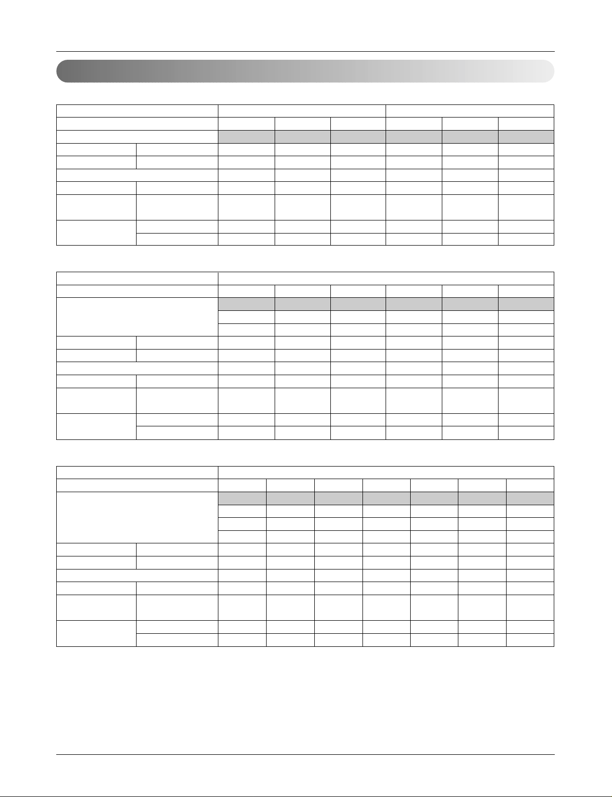
■ Cooling Only
Unit
System(HP)
Model
Product Charge kg
CF(Correction Factor) kg
Max. Connectable No. of Indoor Units
Net Weight kg(lbs)
Dimensions (W x H x D)
mm(inch)
Pipe Connections
Liquid Pipes(mm(inch))
Gas Pipes(mm(inch))
1 Outdoor Unit(Half size) 1 Outdoor Unit
568101214
LRUV508T0 LRUV608T0 LRUV808T0 LRUV1008T0 LRUV1208T0 LRUV1408T0
556101010
000-1-1-1
6 8 13 16 16 16
150(330.7) 150(330.7) 150(330.7) 300(661.4) 300(661.4) 300(661.4)
806 x 1555 x 730 806 x 1555 x 730 806 x 1555 x 730 1280 x 1555 x 730 1280 x 1555 x 730 1280 x 1555 x 730
(31.7 x 61.2 x 28.7) (31.7 x 61.2 x 28.7) (31.7 x 61.2 x 28.7) (50.4 x 61.2 x 28.7) (50.4 x 61.2 x 28.7) (50.4 x 61.2 x 28.7)
Ø9.52(3/8) Ø9.52(3/8) Ø12.7(1/2) Ø12.7(1/2) Ø12.7(1/2) Ø12.7(1/2)
Ø19.05(3/4) Ø22.2(7/8) Ø28.58(11/8) Ø28.58(11/8) Ø28.58(11/8) Ø28.58(11/8)
Unit
System(HP)
Model
Product Charge kg
CF(Correction Factor) kg
Max. Connectable No. of Indoor Units
Net Weight kg(lbs)
Dimensions (W x H x D)
mm(inch)
Pipe Connections
Liquid Pipes(mm(inch))
Gas Pipes(mm(inch))
2 Outdoor Units
3 Outdoor Units
16 18 20 22 24 26
LRUV1608TS0 LRUV1808TS0 LRUV2008TS0 LRUV2208S0 LRUV2408TS0 LRUV2608TR0
LRUV808TS0 LRUV1008TS0 LRUV1008TS0 LRUV1208TS0 LRUV1208TS0 LRUV1008TR0
LRUC808TS0 LRUC808TS0 LRUC1008TS0 LRUC1008TS0 LRUC1208TS0 LRUC808TR0
LRUC808TR0
10 x 2 10 x 2 10 x 2 10 x 2 10 x 2 10 x 3
-2 -2 -2 -2 -2 0
20 20 20 22 24 26
300(661.4) x 2 300(661.4) x 2 300(661.4) x 2 300(661.4) x 2 300(661.4) x 2 300(661.4) x 3
(1280 x 1555 x 730) x 2 (1280 x 1555 x 730) x 2 (1280 x 1555 x 730) x 2 (1280 x 1555 x 730) x 2 (1280 x 1555 x 730) x 2 (1280 x 1555 x 730) x 3
((50.4 x 61.2 x 28.7) x 2) ((50.4 x 61.2 x 28.7) x 2) ((50.4 x 61.2 x 28.7) x 2) ((50.4 x 61.2 x 28.7) x 2) ((50.4 x 61.2 x 28.7) x 2) ((50.4 x 61.2 x 28.7) x 3)
Ø19.05(3/4) Ø19.05(3/4) Ø19.05(3/4) Ø19.05(3/4) Ø19.05(3/4) Ø22.2(7/8)
Ø38.1(11/2) Ø38.1(11/2) Ø38.1(11/2) Ø38.1(11/2) Ø38.1(11/2) Ø44.5(13/4)
Unit
System(HP)
Model
Product Charge kg
CF(Correction Factor) kg
Max. Connectable No. of Indoor Units
Net Weight kg(lbs)
Dimensions (W x H x D)
mm(inch)
Pipe Connections
Liquid Pipes(mm(inch))
Gas Pipes(mm(inch))
3 Outdoor Units
28 30 32 34 36 38 40
LRUV2808TR0 LRUV3008TR0 LRUV3208TR0 LRUV3408TR0 LRUV3608TR0 LRUV3808TR0 LRUV4008TR0
LRUV808TR0 LRUV1008TR0 LRUV1208TR0 LRUV1408TR0 LRUV1208TR0 LRUV1408TR0 LRUV1408TR0
LRUC1008TR0 LRUC1008TR0 LRUC1008TR0 LRUC1008TR0 LRUC1208TR0 LRUC1208TR0 LRUC1408TR0
LRUC1008TR0 LRUC1008TR0 LRUC1008TR0 LRUC1008TR0 LRUC1208TR0 LRUC1208TR0 LRUC1208TR0
10 x 3 10 x 3 10 x 3 10 x 3 10 x 3 10 x 3 10 x 3
0001122
32 32 32 34 36 38 40
300(661.4) x 3 300(661.4) x 3 300(661.4) x 3 300(661.4) x 3 300(661.4) x 3 300(661.4) x 3 300(661.4) x 3
(1280 x 1555 x 730) x 3 (1280 x 1555 x 730) x 3 (1280 x 1555 x 730) x 3 (1280 x 1555 x 730) x 3 (1280 x 1555 x 730) x 3 (1280 x 1555 x 730) x 3 (1280 x 1555 x 730) x 3
((50.4 x 61.2 x 28.7) x 3) ((50.4 x 61.2 x 28.7) x 3) ((50.4 x 61.2 x 28.7) x 3) ((50.4 x 61.2 x 28.7) x 3) ((50.4 x 61.2 x 28.7) x 3) ((50.4 x 61.2 x 28.7) x 3) ((50.4 x 61.2 x 28.7) x 3)
Ø22.2(7/8) Ø22.2(7/8) Ø22.2(7/8) Ø22.2(7/8) Ø22.2(7/8) Ø22.2(7/8) Ø22.2(7/8)
Ø44.5(13/4) Ø44.5(13/4) Ø44.5(13/4) Ø44.5(13/4) Ø44.5(13/4) Ø44.5(13/4) Ø44.5(13/4)
Page 12

12 Outdoor Unit
Outdoor Units Information
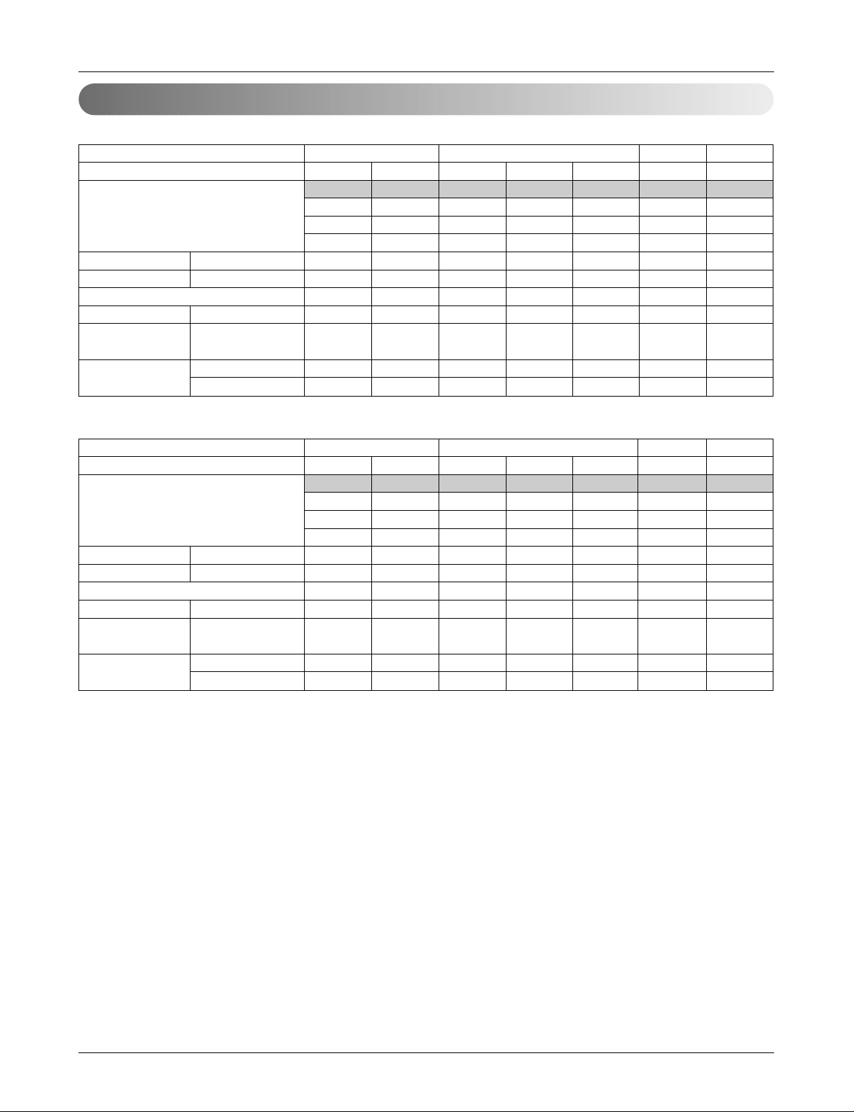
■ Heat Pump
Unit
System(HP)
Model
Product Charge kg
CF(Correction Factor) kg
Max. Connectable No. of Indoor Units
Net Weight kg(lbs)
Dimensions (W x H x D)
mm(inch)
Pipe Connections
Liquid Pipes(mm(inch))
Gas Pipes(mm(inch))
1 Outdoor Unit(Half size)
1 Outdoor Unit
568101214
LRUN508T0 LRUN608T0 LRUN808T0 LRUN1008T0 LRUN1208T0 LRUN1408T0
5 5 10 10 10 10
0 0 -1 -1 -1 -1
6 8 13 16 16 16
150(330.7) 150(330.7) 300(661.4) 300(661.4) 300(661.4) 300(661.4)
806 x 1555 x 730 806 x 1555 x 730 1280 x 1555 x 730 1280 x 1555 x 730 1280 x 1555 x 730 1280 x 1555 x 730
(
31.7 x 61.2 x 28.7) (31.7 x 61.2 x 28.7) (50.4 x 61.2 x 28.7) (50.4 x 61.2 x 28.7) (50.4 x 61.2 x 28.7) (50.4 x 61.2 x 28.7)
Ø9.52(3/8) Ø9.52(3/8) Ø12.7(1/2) Ø12.7(1/2) Ø12.7(1/2) Ø12.7(1/2)
Ø19.05(3/4) Ø22.2(7/8) Ø28.58(11/8) Ø28.58(11/8) Ø28.58(11/8) Ø28.58(11/8)
Unit
System(HP)
Model
Product Charge kg
CF(Correction Factor) kg
Max. Connectable No. of Indoor Units
Net Weight kg(lbs)
Dimensions (W x H x D)
mm(inch)
Pipe Connections
Liquid Pipes(mm(inch))
Gas Pipes(mm(inch))
2 Outdoor Units
3 Outdoor Units
16 18 20 22 24 26
LRUN1608TS0 LRUN1808TS0 LRUN2008TS0 LRUN2208TS0 LRUN2408TS0 LRUN2608TR0
LRUN808TS0 LRUN1008TS0 LRUN1008TS0 LRUN1208TS0 LRUN1208TS0 LRUN1008TR0
LRUH808TS0 LRUH808TS0 LRUH1008TS0 LRUH1008TS0 LRUH1208TS0 LRUH808TR0
LRUH808TR0
10 x 2 10 x 2 10 x 2 10 x 2 10 x 2 10 x 3
-2 -2 -2 -2 -2 0
20 20 20 22 24 26
300(661.4) x 2 300(661.4) x 2 300(661.4) x 2 300(661.4) x 2 300(661.4) x 2 300(661.4) x 3
(1280 x 1555 x 730) x 2 (1280 x 1555 x 730) x 2 (1280 x 1555 x 730) x 2 (1280 x 1555 x 730) x 2 (1280 x 1555 x 730) x 2 (1280 x 1555 x 730) x 3
((50.4 x 61.2 x 28.7) x 2) ((50.4 x 61.2 x 28.7) x 2) ((50.4 x 61.2 x 28.7) x 2) ((50.4 x 61.2 x 28.7) x 2) ((50.4 x 61.2 x 28.7) x 2) ((50.4 x 61.2 x 28.7) x 3)
Ø19.05(3/4) Ø19.05(3/4) Ø19.05(3/4) Ø19.05(3/4) Ø19.05(3/4) Ø22.2(7/8)
Ø38.1(11/2) Ø38.1(11/2) Ø38.1(11/2) Ø38.1(11/2) Ø38.1(11/2) Ø44.5(13/4)
Unit
System(HP)
Model
Product Charge kg
CF(Correction Factor) kg
Max. Connectable No. of Indoor Units
Net Weight kg(lbs)
Dimensions (W x H x D)
mm(inch)
Pipe Connections
Liquid Pipes(mm(inch))
Gas Pipes(mm(inch))
3 Outdoor Units
28 30 32 34 36 38 40
LRUN2808TR0 LRUN3008TR0 LRUN3208TR0 LRUN3408TR0 LRUN3608TR0 LRUN3808TR0 LRUN4008TR0
LRUN808TR0 LRUN1008TR0 LRUN1208TR0 LRUN1408TR0 LRUN1208TR0 LRUN1408TR0 LRUN1408TR0
LRUH1008TR0 LRUH1008TR0 LRUH1008TR0 LRUH1008TR0 LRUH1208TR0 LRUH1208TR0 LRUH1408TR0
LRUH1008TR0 LRUH1008TR0 LRUH1008TR0 LRUH1008TR0 LRUH1208TR0 LRUH1208TR0 LRUH1208TR0
10 x 3 10 x 3 10 x 3 10 x 3 10 x 3 10 x 3 10 x 3
0001122
32 32 32 34 36 38 40
300(661.4) x 3 300(661.4) x 3 300(661.4) x 3 300(661.4) x 3 300(661.4) x 3 300(661.4) x 3 300(661.4) x 3
(1280 x 1555 x 730) x 3 (1280 x 1555 x 730) x 3 (1280 x 1555 x 730) x 3 (1280 x 1555 x 730) x 3 (1280 x 1555 x 730) x 3 (1280 x 1555 x 730) x 3 (1280 x 1555 x 730) x 3
((50.4 x 61.2 x 28.7) x 3) ((50.4 x 61.2 x 28.7) x 3) ((50.4 x 61.2 x 28.7) x 3) ((50.4 x 61.2 x 28.7) x 3) ((50.4 x 61.2 x 28.7) x 3) ((50.4 x 61.2 x 28.7) x 3) ((50.4 x 61.2 x 28.7) x 3)
Ø22.2(7/8) Ø22.2(7/8) Ø22.2(7/8) Ø22.2(7/8) Ø22.2(7/8) Ø22.2(7/8) Ø22.2(7/8)
Ø44.5(13/4) Ø44.5(13/4) Ø44.5(13/4) Ø44.5(13/4) Ø44.5(13/4) Ø44.5(13/4) Ø44.5(13/4)
Page 13
Installation Manual 13
Outdoor Units Information
Power Supply: Outdoor Unit (3Ø, 380V, 60Hz)
■ Cooling Only
Unit
System(HP)
Model
Product Charge kg
CF(Correction Factor) kg
Max. Connectable No. of Indoor Units
Net Weight kg(lbs)
Dimensions (W x H x D)
mm(inch)
Pipe Connections
Liquid Pipes(mm(inch))
Gas Pipes(mm(inch))
1 Outdoor Unit(Half size) 1 Outdoor Unit
568101214
LRUV509T0 LRUV609T0 LRUV809T0 LRUV1009T0 LRUV1209T0 LRUV1409T0
556101010
000-1-1-1
6 8 13 16 16 16
150(330.7) 150(330.7) 150(330.7) 300(661.4) 300(661.4) 300(661.4)
806 x 1555 x 730 806 x 1555 x 730 806 x 1555 x 730 1280 x 1555 x 730 1280 x 1555 x 730 1280 x 1555 x 730
(31.7 x 61.2 x 28.7) (31.7 x 61.2 x 28.7) (31.7 x 61.2 x 28.7) (50.4 x 61.2 x 28.7) (50.4 x 61.2 x 28.7) (50.4 x 61.2 x 28.7)
Ø9.52(3/8) Ø9.52(3/8) Ø12.7(1/2) Ø12.7(1/2) Ø12.7(1/2) Ø12.7(1/2)
Ø19.05(3/4) Ø22.2(7/8) Ø28.58(11/
8) Ø28.58(1
1
/
8) Ø28.58(1
1
/
8) Ø28.58(1
1
/
8)
Unit
System(HP)
Model
Product Charge kg
CF(Correction Factor) kg
Max. Connectable No. of Indoor Units
Net Weight kg(lbs)
Dimensions (W x H x D)
mm(inch)
Pipe Connections
Liquid Pipes(mm(inch))
Gas Pipes(mm(inch))
2 Outdoor Units
16 18 20 22 24 26
LRUV1609TS0 LRUV1809TS0 LRUV2009TS0 LRUV2209TS0 LRUV2409TS0 LRUV2609TS0
LRUV809TS0 LRUV1009TS0 LRUV1009TS0 LRUV1209TS0 LRUV1209TS0 LRUV1409TS0
LRUC809TS0 LRUC809TS0 LRUC1009TS0 LRUC1009TS0 LRUC1209TS0 LRUC1209TS0
10 x 2 10 x 2 10 x 2 10 x 2 10 x 2 10 x 2
-2 -2 -2 -2 -2 -1
20 20 20 22 24 26
300(661.4) x 2 300(661.4) x 2 300(661.4) x 2 300(661.4) x 2 300(661.4) x 2 300(661.4) x 2
(1280 x 1555 x 730) x 2 (1280 x 1555 x 730) x 2 (1280 x 1555 x 730) x 2 (1280 x 1555 x 730) x 2 (1280 x 1555 x 730) x 2 (1280 x 1555 x 730) x 2)
((50.4 x 61.2 x 28.7) x 2) ((50.4 x 61.2 x 28.7) x 2) ((50.4 x 61.2 x 28.7) x 2) ((50.4 x 61.2 x 28.7) x 2) ((50.4 x 61.2 x 28.7) x 2) ((50.4 x 61.2 x 28.7) x 2)
Ø19.05(3/4) Ø19.05(3/4) Ø19.05(3/4) Ø19.05(3/4) Ø19.05(3/4) Ø19.05(3/4)
Ø38.1(11/2) Ø38.1(11/2) Ø38.1(11/2) Ø38.1(11/2) Ø38.1(11/2) Ø38.1(11/2)
Unit
System(HP)
Model
Product Charge kg
CF(Correction Factor) kg
Max. Connectable No. of Indoor Units
Net Weight kg(lbs)
Dimensions (W x H x D)
mm(inch)
Pipe Connections
Liquid Pipes(mm(inch))
Gas Pipes(mm(inch))
3 Outdoor Units
28 30 32 34 36 38 40
LRUV2809TR0 LRUV3009TR0 LRUV3209TR0 LRUV3409TR0 LRUV3609TR0 LRUV3809TR0 LRUV4008TR0
LRUV809TR0 LRUV1009TR0 LRUV1209TR0 LRUV1409TR0 LRUV1209TR0 LRUV1409TR0 LRUV1409TR0
LRUC1009TR0 LRUC1009TR0 LRUC1009TR0 LRUC1009TR0 LRUC1209TR0 LRUC1209TR0 LRUC1409TR0
LRUC1009TR0 LRUC1009TR0 LRUC1009TR0 LRUC1009TR0 LRUC1209TR0 LRUC1209TR0 LRUC1209TR0
10 x 3 10 x 3 10 x 3 10 x 3 10 x 3 10 x 3 10 x 3
0001122
32 32 32 34 36 38 40
300(661.4) x 3 300(661.4) x 3 300(661.4) x 3 300(661.4) x 3 300(661.4) x 3 300(661.4) x 3 300(661.4) x 3
(1280 x 1555 x 730) x 3 (1280 x 1555 x 730) x 3 (1280 x 1555 x 730) x 3 (1280 x 1555 x 730) x 3 (1280 x 1555 x 730) x 3 (1280 x 1555 x 730) x 3 (1280 x 1555 x 730) x 3
((50.4 x 61.2 x 28.7) x 3) ((50.4 x 61.2 x 28.7) x 3) ((50.4 x 61.2 x 28.7) x 3) ((50.4 x 61.2 x 28.7) x 3) ((50.4 x 61.2 x 28.7) x 3) ((50.4 x 61.2 x 28.7) x 3) ((50.4 x 61.2 x 28.7) x 3)
Ø22.2(7/8) Ø22.2(7/8) Ø22.2(7/8) Ø22.2(7/8) Ø22.2(7/8) Ø22.2(7/8) Ø22.2(7/8)
Ø
44.5(13/4)Ø44.5(13/4)Ø44.5(13/4)Ø44.5(13/4)Ø44.5(13/4)Ø44.5(13/4)Ø44.5(13/4)
Page 14

14 Outdoor Unit
Outdoor Units Information
■ Heat Pump
Unit
System(HP)
Model
Product Charge kg
CF(Correction Factor) kg
Max. Connectable No. of Indoor Units
Net Weight kg(lbs)
Dimensions (W x H x D)
mm(inch)
Pipe Connections
Liquid Pipes(mm(inch))
Gas Pipes(mm(inch))
1 Outdoor Unit(Half size)
1 Outdoor Unit
568101214
LRUN509T0 LRUN609T0 LRUN809T0 LRUN1009T0 LRUN1209T0 LRUN1409T0
5 5 10 10 10 10
0 0 -1 -1 -1 -1
6 8 13 16 16 16
150(330.7) 150(330.7) 300(661.4) 300(661.4) 300(661.4) 300(661.4)
806 x 1555 x 730 806 x 1555 x 730 1280 x 1555 x 730 1280 x 1555 x 730 1280 x 1555 x 730 1280 x 1555 x 730
(31.7 x 61.2 x 28.7) (31.7 x 61.2 x 28.7) (50.4 x 61.2 x 28.7) (50.4 x 61.2 x 28.7) (50.4 x 61.2 x 28.7) (50.4 x 61.2 x 28.7
Ø9.52(3/8) Ø9.52(3/8) Ø12.7(1/2) Ø12.7(1/2) Ø12.7(1/2) Ø12.7(1/2)
Ø19.05(3/4) Ø22.2(7/8) Ø28.58(11/8) Ø28.58(11/8) Ø28.58(11/8) Ø28.58(11/8)
Unit
System(HP)
Model
Product Charge kg
CF(Correction Factor) kg
Max. Connectable No. of Indoor Units
Net Weight kg(lbs)
Dimensions (W x H x D)
mm(inch)
Pipe Connections
Liquid Pipes(mm(inch))
Gas Pipes(mm(inch))
2 Outdoor Units
16 18 20 22 24 26
LRUN1609TS0 LRUN1809TS0 LRUN2009TS0 LRUN2209TS0 LRUN2409TS0 LRUN2609TS0
LRUN809TS0 LRUN1009TS0 LRUN1009TS0 LRUN1209TS0 LRUN1209TS0 LRUN1409TS0
LRUH809TS0 LRUH809TS0 LRUH1009TS0 LRUH1009TS0 LRUH1209TS0 LRUH1209TS0
10 x 2 10 x 2 10 x 2 10 x 2 10 x 2 10 x 2
-2 -2 -2 -2 -2 -1
20 20 20 22 24 26
300(661.4) x 2 300(661.4) x 2 300(661.4) x 2 300(661.4) x 2 300(661.4) x 2 300(661.4) x 2
(1280 x 1555 x 730) x 2 (1280 x 1555 x 730) x 2 (1280 x 1555 x 730) x 2 (1280 x 1555 x 730)) x 2 (1280 x 1555 x 730) x 2 (1280 x 1555 x 730) x 2
((50.4 x 61.2 x 28.7) x 2) ((50.4 x 61.2 x 28.7) x 2) ((50.4 x 61.2 x 28.7) x 2) ((50.4 x 61.2 x 28.7) x 2) ((50.4 x 61.2 x 28.7) x 2) ((50.4 x 61.2 x 28.7) x 2)
Ø19.05(3/4) Ø19.05(3/4) Ø19.05(3/4) Ø19.05(3/4) Ø19.05(3/4) Ø19.05(3/4)
Ø38.1(11/
2) Ø38.1(1
1
/
2) Ø38.1(1
1
/
2) Ø38.1(1
1
/
2) Ø38.1(1
1
/
2) Ø38.1(1
1
/
2)
Unit
System(HP)
Model
Product Charge kg
CF(Correction Factor) kg
Max. Connectable No. of Indoor Units
Net Weight kg(lbs)
Dimensions (W x H x D)
mm(inch)
Pipe Connections
Liquid Pipes(mm(inch))
Gas Pipes(mm(inch))
3 Outdoor Units
28 30 32 34 36 38 40
LRUN2809TR0 LRUN3009TR0 LRUN3209TR0 LRUN3409TR0 LRUN3609TR0 LRUN3809TR0 LRUN4009TR0
LRUN809TR0 LRUN1009TR0 LRUN1209TR0 LRUN1409TR0 LRUN1209TR0 LRUN1409TR0 LRUN1409TR0
LRUH1009TR0 LRUH1009TR0 LRUH1009TR0 LRUH1009TR0 LRUH1209TR0 LRUH1209TR0 LRUH1409TR0
LRUH1009TR0 LRUH1009TR0 LRUH1009TR0 LRUH1009TR0 LRUH1209TR0 LRUH1209TR0 LRUH1209TR0
10 x 3 10 x 3 10 x 3 10 x 3 10 x 3 10 x 3 10 x 3
0001122
32 32 32 34 36 38 40
300(661.4) x 3 300(661.4) x 3 300(661.4) x 3 300(661.4) x 3 300(661.4) x 3 300(661.4) x 3 300(661.4) x 3
(1280 x 1555 x 730) x 3 (1280 x 1555 x 730) x 3 (1280 x 1555 x 730) x 3 (1280 x 1555 x 730) x 3 (1280 x 1555 x 730) x 3 (1280 x 1555 x 730) x 3 (1280 x 1555 x 730) x 3
((50.4 x 61.2 x 28.7) x 3) ((50.4 x 61.2 x 28.7) x 3) ((50.4 x 61.2 x 28.7) x 3) ((50.4 x 61.2 x 28.7) x 3) ((50.4 x 61.2 x 28.7) x 3) ((50.4 x 61.2 x 28.7) x 3) ((50.4 x 61.2 x 28.7) x 3)
Ø22.2(7/8) Ø22.2(7/8) Ø22.2(7/8) Ø22.2(7/8) Ø22.2(7/8) Ø22.2(7/8) Ø22.2(7/8)
Ø
44.5(13/4)Ø44.5(13/4)Ø44.5(13/4)Ø44.5(13/4)Ø44.5(13/4)Ø44.5(13/4)Ø44.5(13/4)
Page 15
Installation Manual 15
Outdoor Units Information
Power Supply: Outdoor Unit (3Ø, 220V, 60Hz)
■ Cooling Only
■ Heat Pump
Unit
System(HP)
Model
Product Charge kg
CF(Correction Factor) kg
Max. Connectable No. of Indoor Units
Net Weight kg(lbs)
Dimensions (W x H x D)
mm(inch)
Pipe Connections
Liquid Pipes(mm(inch))
Gas Pipes(mm(inch))
1 Outdoor Unit(Half size)
1 Outdoor Unit
2 Outdoor Units 3 Outdoor Units
5 6 8 10122030
LRUV50BT0 LRUV60BT0 LRUV80BT0 LRUV100BT0 LRUV120BT0 LRUV200BTS0 LRUV300BTR0
LRUV100BTS0 LRUV100BTR0
LRUC100BTS0 LRUC100BTR0
LRUC100BTR0
5 5 10 10 10 10 x 2 10 x 3
0 0 -1 -1 -1 -2 0
6 8 13 16 16 20 32
150(330.7) 150(330.7) 300(661.4) 300(661.4) 300(661.4) 300(661.4) x 2 300(661.4) x 3
806 x 1555 x 730 806 x 1555 x 730 1280 x 1555 x 730 1280 x 1555 x 730 1280 x 1555 x 730
(1280 x 1555 x 730) x 2 (1280 x 1555 x 730) x 3
(31.7 x 61.2 x 28.7) (31.7 x 61.2 x 28.7) (50.4 x 61.2 x 28.7) (50.4 x 61.2 x 28.7) (50.4 x 61.2 x 28.7)
((50.4 x 61.2 x 28.7) x 2) ((50.4 x 61.2 x 28.7) x 3)
Ø9.52(3/8) Ø9.52(3/8) Ø12.7(1/2) Ø12.7(1/2) Ø12.7(1/2) Ø19.05(3/4) Ø22.2(7/8)
Ø19.05(3/4) Ø22.2(7/8)
Ø28.58
(11/8)
Ø28.58
(11/8)
Ø28.58
(11/8)
Ø38.1(11/2) Ø44.5(13/4)
Unit
System(HP)
Model
Product Charge kg
CF(Correction Factor) kg
Max. Connectable No. of Indoor Units
Net Weight kg(lbs)
Dimensions (W x H x D)
mm(inch)
Pipe Connections
Liquid Pipes(mm(inch))
Gas Pipes(mm(inch))
1 Outdoor Unit(Half size)
1 Outdoor Unit
2 Outdoor Units 3 Outdoor Units
5 6 8 10122030
LRUN50BT0 LRUN60BT0 LRUN80BT0 LRUN100BT0 LRUN120BT0 LRUN200BTS0 LRUN300BTR0
LRUN100BTS0 LRUN100BTR0
LRUH100BTS0 LRUH100BTR0
LRUH100BTR0
5 5 10 10 10 10 x 2 10 x 3
0 0 -1 -1 -1 -2 0
6 8 13 16 16 20 32
150(330.7) 150(330.7) 300(661.4) 300(661.4) 300(661.4) 300(661.4) x 2 300(661.4) x 3
806 x 1555 x 730 806 x 1555 x 730 1280 x 1555 x 730 1280 x 1555 x 730 1280 x 1555 x 730 (1280 x 1555 x 730) x 2 (1280 x 1555 x 730) x 3
(31.7 x 61.2 x 28.7) (31.7 x 61.2 x 28.7) (50.4 x 61.2 x 28.7) (50.4 x 61.2 x 28.7) (50.4 x 61.2 x 28.7)
((50.4 x 61.2 x 28.7) x 2) ((50.4 x 61.2 x 28.7) x 3)
Ø12.7(1/2) Ø12.7(1/2) Ø12.7(1/2) Ø12.7(1/2) Ø12.7(1/2) Ø19.05(3/4) Ø22.2(7/8)
Ø19.05(3/4) Ø19.05(3/4) Ø28.58(9/8) Ø28.58(9/8) Ø28.58(9/8) Ø38.1(11/
2) Ø44.5(1
3
/
4)
Page 16

16 Outdoor Unit
Select the Best Location
Select the Best Location
Select space for installing Outdoor Unit, which will meet the following conditions:
• No direct thermal radiation from other heat sources
• No possibility of annoying the neighbors by noise from unit
• No exposition to strong wind
• With strength which bears weight of unit
• Note that drain flows out of unit when heating
• With space for air passage and service work shown next
• Because of the possibility of fire, do not install unit to the space where generation, inflow, stagnation, and leak
of combustible gas is expected.
• Avoid unit installation in a place where acidic solution and spray (sulfur) are often used.
• Do not use unit under any special environment where oil, steam and sulfuric gas exist.
• It is recommended to fence round the Outdoor Unit in order to prevent any person or animal from accessing
the Outdoor Unit.
• If installation site is area of heavy snowfall, then the following directions should be observed.
- Make the foundation as high as possible.
- Fit a snow protection hood.
• Select installation location considering following conditions to avoid bad condition when additionally performing
defrost operation.
1. Install the outdoor unit at a place well ventilated and having a lot of sunshine in case of installing the product at a place with a high humidity in winter (neare beach, coast, lake, etc).
(Ex) Rooftop where sunshine always shines.
2. Performance of heating will be reduced and preheat time of the indoor unit may be lengthened in case of
installing the outdoor unit in winter at following location:
(1) Shade position with a narrow space
(2) Location with much moisture in neighboring floor.
(3) Location with much humidity around.
(4) Location where ventilation is good.
It is recommended to install the outdoor unit at a place with a lot of sunshine as possible as.
(5) Location where water gathers since the floor is not even.
Page 17

Installation Manual 17
Installation Space
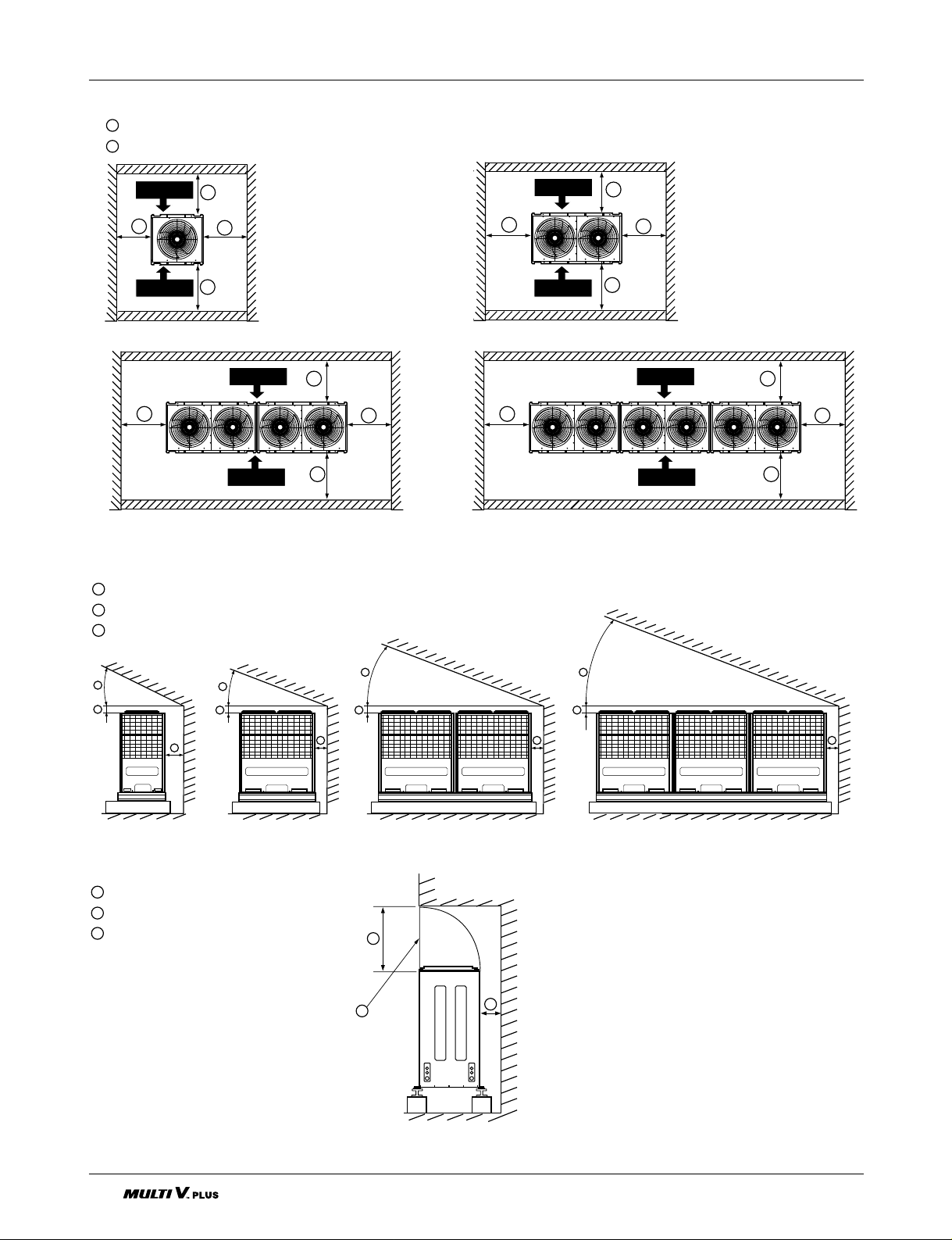
Installation Space
Individual Installation
■ Basic space required
A space of at least 250 mm is necessary at the back for inlet air. Taking servicing, etc. from the rear into
account, a space of about 900 mm should be provided, the same as at the front.
■ When inlet air enters from right and left sides of unit
250 mm or more
900 mm or more (Control box is of a open/close type)
Top discharge (open in principle)
Front inlet (open in principle)
Rear inlet (open in principle)
A
B
C
D
E
C
ED
A
B
Control Box
Front Side
Rear Side
A
B
Control Box
Front Side
Rear Side
A
B
Control Box
Front Side
Rear Side
A
B
C
900 mm or more(Control box is of a open/close type)
250 mm or more
150 mm from the wall
C
A
B
C
A
B
h
H
Front Side
Rear Side
C
A
B
C
Front Side
Rear Side
C
A
B
C
Front Side
Rear Side
C
A
B
C
A
B
Control Box
Front Side
Rear Side
Front Side
Rear Side
< Side view > < Top view >
< Side view > < Top view >
CAUTION
Wall height(H) must not
exceed height of the
product. If the wall height
is higher than the whole
height of product by (h),
Add (h) to
, .
Page 18
18 Outdoor Unit
Installation Space
E
D
F
A
B
C
A
B
C
A
B
C
45° or more
200 mm or more
250 mm or more
A
B
C
1000 mm or more
Air outlet guide (Procured at the site)
250 mm or more
D
E
F
A
B
C
< Front view >
< Side view >
■ When unit is surrounded by walls
900 mm or more (Control box is of a open/close type)
250 mm or more
A
B
A
B
B
B
Front Side
Rear Side
A
B
B
B
Front Side
Rear Side
A
B
B
B
Front Side
Rear Side
Front Side
Rear Side
A
B
B
B
■ When there is an obstruction above the unit
Page 19

Installation Manual 19
Installation Space
Collective / Continuous installation
Space required for collective installation and continuous installation:When installing several units, leave
the space between each block as shown below considering passage for air and people.
(Be opened)
900mm or more (control box is of a open/close type)
250 mm or more
A
B
C
Front Side
Rear Side
Rear Side
Front Side
Rear Side
Front Side
Rear Side
Front Side
Rear Side
Front Side
Rear Side
Front Side
Rear Side
Front Side
Rear Side
Front Side
Rear Side
Front Side
Rear Side
Front Side
Rear Side
Front Side
Rear Side
Front Side
Rear Side
Front Side
Rear Side
Front Side
Rear Side
Front Side
Rear Side
Front Side
Rear Side
Front Side
Front Side
Rear Side
Front Side
Rear Side
Front Side
Rear Side
Front Side
Rear Side
Front Side
Rear Side
Front Side
Rear Side
Front Side
Rear Side
Front Side
Rear Side
Front Side
Rear Side
Front Side
Rear Side
Front Side
Rear Side
Front Side
Rear Side
Front Side
Rear Side
Front Side
Rear Side
Front Side
Rear Side
Front Side
Rear Side
Front Side
Rear Side
Front Side
Rear Side
Front Side
Rear Side
Page 20

20 Outdoor Unit
Seasonal wind and cautions in winter
• Sufficient measures are required at a snow area or severe cold area in winter so that product can be operated
well.
• Get ready for seasonal wind or snow in winter even in other area.
• Install a suction and discharge duct not to let in snow or rain when the product operates at outdoor temperature
of less than 10°C.
• Install the outdoor unit not to come in contact with snow directly. If snow piles up and freezes on the air suction
hole, the system may malfunction. If it is installed at snowy area, attach the hood to the system.
• Install the outdoor unit at the higher installation console by 50cm than the average snowfall (annual average
snowfall) if it is installed at the area with much snowfall.
• Where snow accumulated on the upper part of the Outdoor Unit by more than 10cm, always remove snow for
operation.
1. The height of H frame must be more than 2 times the snowfall and its width shall not exceed the width of the
product. (If width of the frame is wider than that of the product, snow may accumulate)
2. Don't install the suction hole and discharge hole of the Outdoor Unit facing to the seasonal wind.
CAUTION
• Always apply main power of the outdoor unit during use of product
(cooling season/heating season).
Lifting Method
• Always apply power before 6 hours to heat the crank case heater where performing test run after installation
of product or where operating the product after cutting the main power of the outdoor unit (for example,
power failure). It may result in burning out of the compressor if not preheating the crank case with the
electrical heater for more than 6 hours. (In case of the outdoor temperature below 10°C)
Page 21
Installation Manual 21
Lifting Method
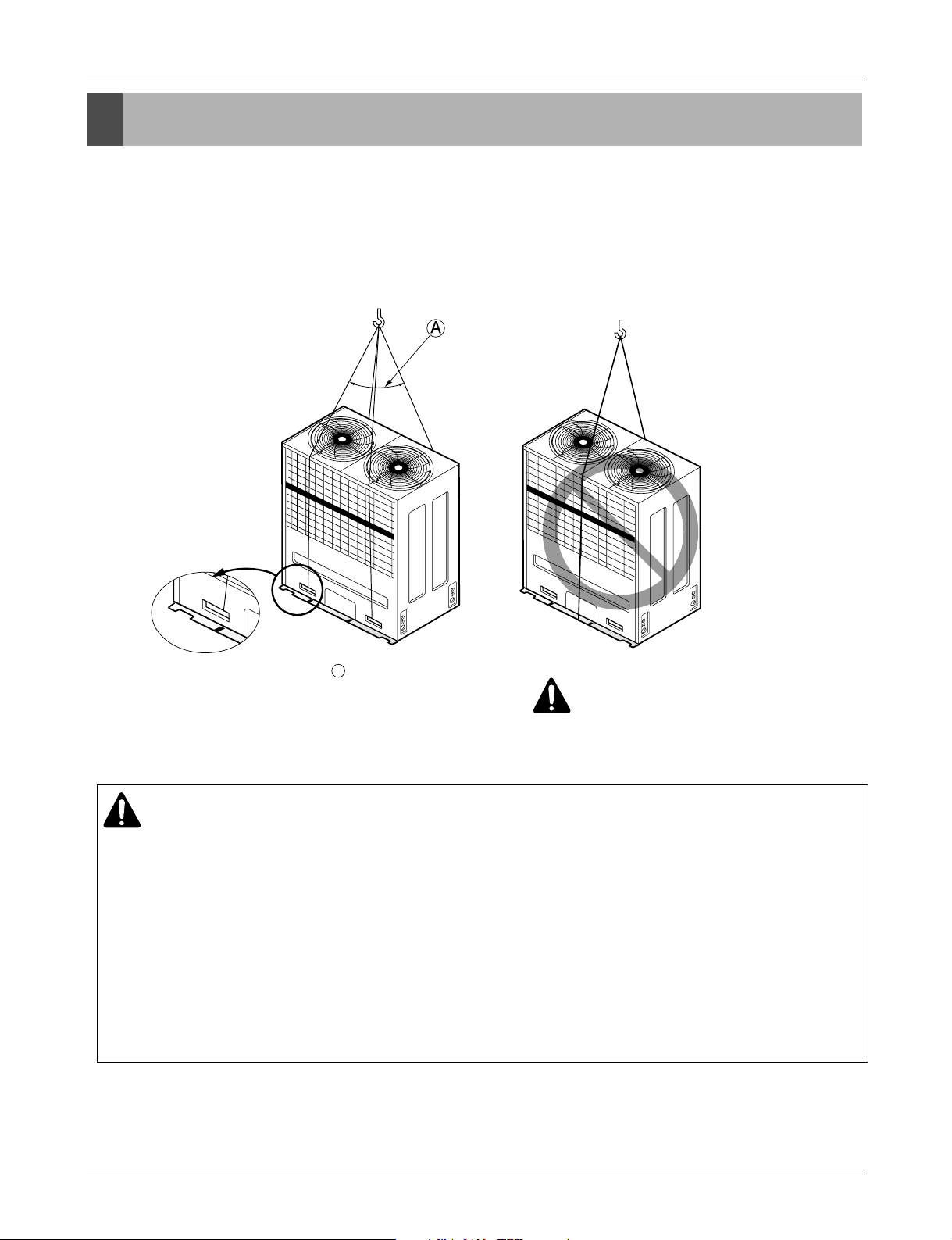
• When carrying the unit suspended, pass the ropes under the unit and use the two suspension points each at
the front and rear.
• Always lift the unit with ropes attached at four points so that impact is not applied to the unit.
• Attach the ropes to the unit at an angle of 40° or less.
Lifting method
CAUTION
Be very careful to carry product.
• Do not have only one person carry product if it is more than 20 kg.
• PP bands are used to pack some products. Do not use them as a mean for transportation because they
are dangerous.
• Do not touch heat exchanger fins with your bare hands. Otherwise you may get a cut in your hands.
• Tear plastic packaging bag and scrap it so that children cannot play with it. Otherwise plastic packaging
bag may suffocate children to death.
• When carrying in Outdoor Unit, be sure to support it at four points. Carrying in and lifting with 3-point
support may make Outdoor Unit unstable, resulting in a fall of it.
A
40° or less
WARNING
Page 22

22 Outdoor Unit
Installation
Location of anchor bolt
Installation
■ Individual installation
■ Example of collective installation
■ Installation foot (Location of anchor bolt)
700
10
900
383
900
700
900
700
900
700
900
10
383
900
10
383
900
900
10
383
900
383
900
10
383
900
10
383
900
10
383
900
10
Half size
Page 23

Installation Manual 23
Installation
Foundation for Installation
• Fix the unit tightly with bolts as shown below so that unit will not fall down due to earthquake or gust.
• Use the H-beam support as a base support
• Noise and vibration may occur from the floor or wall since vibration is transferred through the installation
part depending on installation status. Thus, use anti-vibration materials (cushion pad) fully (The base pad
shall be more than 200mm).
A
B
D
E
F
G
C
G
Ensure that the corner part can be securely mounted. Otherwise, the support for
installation may be bent.
Obtain and use the M10 anchor bolt.
The corner was not properly mounted.
Outdoor unit (Insert the cushion pad between outdoor unit and base support to ensure that
anti-vibration may be done in a wide area)
Pipe and wiring space (in case of piping and wiring on the floor surface)
H-Beam support
Concrete base support
WARNING
• Be sure to install unit in a place strong enough to withstand its weight.
Any lack of strength may cause unit to fall down, resulting in a personal injury.
• Have installation work in order to protect against a strong wind and earthquake. Any installation
deficiency may cause unit to fall down, resulting in a personal injury.
• Especially take care for support strength of the floor surface, water drain processing (processing of
water flown out from the Outdoor Unit during operation) and paths of the pipe and wiring when
making a base support.
• Don't use a tube or pipe for water drain in the base pan and perform water drain processing by
using the drain path. Water drain may not be done due to freezing of a tube or pipe.
Rear Side Side Side
Water
Drain
Path
Page 24

24 Outdoor Unit
Appendix
Preparation of Piping
1) Cut the pipes and the cable.
■ Use the accessory piping kit or the pipes purchased
locally.
■ Measure the distance between the indoor and the
Outdoor Unit.
■ Cut the pipes a little longer than measured distance.
■ Cut the cable 1.5m longer than the pipe length.
2) Burrs removal
■ Completely remove all burrs from the cut cross section
of pipe/tube.
■ Put the end of the copper tube/pipe to downward direction as you remove burrs in order to avoid to let burrs
drop in the tubing.
3) Flaring work
■ Carry out flaring work using flaring tool as shown below.
Exception)
Wide Art Cool(4.0kW(13,600 Btu/h): Gas pipe(5/8"),
Liquid pipe(3/8")
Firmly hold copper tube in a bar(or die) as indicated
dimension in the table above.
4) Check
■ Compare the flared work with figure below.
■ If flare is noted to be defective, cut off the flared section
and do flaring work again.
Main cause of gas leakage is defect in flaring work. Carry out correct flaring work in the following procedure.
Pipe " A "
Gas Liquid Gas
Liquid
~4.0(13,600) 1/2" 1/4" 0.5~0.8 0~0.5
~9.0(30,700) 5/8" 3/8" 0.8~1.0 0.5~0.8
~15.0(51,200) 3/4" 3/8" 1.0~1.3 0.5~0.8
Indoor Unit
[kW(Btu/h]
Copper
tube
90°
Slanted Uneven Rough
Pipe
Reamer
Point down
Bar
Copper pipe
Clamp handle
Red arrow mark
Cone
Yoke
Handle
Bar
"A"
Inclined
Inside is shining without scratches.
Smooth all round
Even length
all round
Surface
damaged
Cracked Uneven
thickness
= Improper flaring =
Page 25
Installation Manual 25
Appendix
1. Form the piping according to its routing. Avoid bending and bending back the same piping point more than
three times. (This will result in hardening the pipe.)
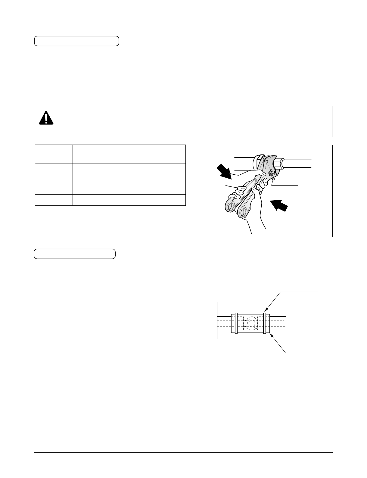
2. After deforming the piping, align centers of the union fitting of the Indoor Unit and the piping, and tighten
them firmly with wrenches.
3. Connect pipe to the service valve or ball valve which is located below the Outdoor Unit.
4. After completing the piping connection, be sure to check if there is gas leakage in indoor and outdoor connection.
Union
Pipe size Flare nut fastening torque (N.m)
Ø6.35mm 14~18
Ø9.52mm 35~42
Ø12.7mm 50~57.5
Ø15.88mm 75~80
Ø19.05mm 100~140
Piping Connection
CAUTION
Use two wrenches and tighten with regular torque.
1. Use the heat insulation material for the refrigerant piping which has an excellent heat-resistance (over
120°C).
2. Precautions in high humidity circumstance:
This air conditioner has been tested according to the
"KS Standard Conditions with Mist" and confirmed
that there is not any default. However, if it is operated
for a long time in high humid atmosphere (dew point
temperature: more than 23°C), water drops are liable
to fall. In this case, add heat insulation material
according to the following procedure:
• Heat insulation material to be prepared... Adiabatic
glass wool with thickness 10 to 20mm.
• Stick glass wool on all air conditioners that are located in ceiling atmosphere.
• In addition to the normal heat insulation (thickness: more than 8mm) for refrigerant piping (gas piping: thick
piping) and drain piping, add further 10mm to 30mm thickness material.
Indoor Unit
Thermal insulator
(accessory)
Fastening band
(accessory)
Refrigerant piping
HEAT INSULATION
Page 26

26 Outdoor Unit
Refrigerant piping installation
WARNING
After completing work, securely tighten both service ports and caps so that gas does not leak.
Refrigerant piping installation
The method of connection consists of flare connections at the Indoor Units, flange connections for the piping of
the Outdoor Unit and flare connections for the liquid piping. Note that the branched sections are brazed.
WARNING
Always use extreme care to prevent the refrigerant gas (R22) from the leakage while using fire or
flame. If the refrigerant gas comes in contact with the flame from any source, such as a gas stove, it
breaks down and generates a poisonous gas which can cause gas poisoning. Never weld in an
unventilated room. Always conduct an inspection for gas leakage after installation of the refrigerant
piping has been completed.
Pipe joint (auxiliary parts): Securely perform welding by
passing nitrogen through the service valve port.
Flare nut: Loose or tighten flare nut by using the wrench
with both ends. Coat the flare connection part with oil for
a refrigerator.
Cap: Remove caps and operate valve, etc. After operation, always reattach caps (tightening torque of valve
cap: 25Nm (250kg-cm) or more).
Service port: Make the refrigerant pipe empty and use
the service port for filling additional refrigerant. Always
reattach caps after completing work (tightening torque of
service cap: 14Nm (140kg-cm) or more).
Liquid pipe
Gas pipe
Elbow joint: Elbow welding (Non-acid welding in welding)
Cautions in pipe connection/valve operation
Open status when both the pipe and
the valve are in a straight line.
Cut both the pipe and the valve with a
cutter to suit the length
(Don't cut the length of less than 70mm)
Elbow
Ball Valv e(Gas Pipe)
Ball Valv e(Liquid Pipe)
Page 27

Installation Manual 27
Refrigerant piping installation
Connection of High/Low Pressure Common pipe
1. For the High/Low Pressure Common pipe, connect both Main Outdoor Unit and Sub (1, 2) Outdoor Unit to the pipe by
using elbows supplied field.
2. For cutting the pipe, connect the High/Low Pressure Common pipe after removing burrs, dusts and foreign materials
within the pipe. Otherwise, the product may not operate due to sludge within the pipe.
3. For leakage inspection of the work part, pressurize nitrogen gas by 2.94MPa (30kgf/cm
2
).
4. Continue vacuum work after the vacuum degree reaches to 5Torr
5. Open side bar with the hex wrench.
Connect the pipe by using Gas pipe Pressure
connection elbow. For installing the pipe in the
front after cutting part in a saw, install the
only pipe knock out hole part. For installing
the pipe in side, install the whole of pipe knock
out.
Sub
Outdoor Unit
Main
Outdoor Unit
2 Outdoor Units 3 Outdoor Units
WARNING
After installing the pipe, clog the pipe excavation inlet of the front panel and the side panel
(Wire may be damaged due to entering of rats, animals, etc).
Sub2
Outdoor
Unit
Sub1
Outdoor
Unit
Main
Outdoor Unit
Knock out
Transmission Line Hole
Power Cable Hole
Pipe Hole
(Front) (Side)
Page 28

28 Outdoor Unit
Ø 28.58
Ø 38.1
❈ Branch Pipe for Connection between Outdoor Units: ARBL202C ❈ Branch Pipe for Connection between Outdoor Units: ARBL302C
❈ Branch Pipe for Connection between Outdoor Units: ARBL202C ❈ Branch Pipe for Connection between Outdoor Units: ARBL302C
Main Pipe
Main Pipe
Sub2 + Sub1 Outdoor
Unit Connection Pipe
Sub1 Outdoor Unit
Main Outdoor Unit
Ø 12.7
Ø 12.7
Ø 12.7
Sub1 + Main Outdoor
Unit Connection Pipe
After cutting to length
(Don't cut the pipe of
less than 70mm)
Sub2 + Sub1 Outdoor
Unit Connection Pipe
Sub1 Outdoor Unit
Gas Pipe
Sub1 Outdoor
Unit Gas Pipe
Weld elbow while
flowing nitrogen.
After cutting to length
(Don't cut the pipe of
less than 70mm)
Sub1 + Main Outdoor
Unit Connection Pipe
Main Outdoor Unit
Gas Pipe
Main Outdoor
Unit Gas Pipe
Weld elbow while
flowing nitrogen.
Ø 44.5
Ø 19.05
Ø 22.2
Ø 19.05
Ø 28.58
Ø 38.1
Ø 28.58
Refrigerant piping installation
2 Outdoor Units
3 Outdoor Units
CAUTION
Both the High/Low Pressure Common pipe and the Liquid pipe shall be insulated by insulation material.
Connection of Gas pipe Connection of Liquid pipe
Connection of Liquid(Gas) pipe
Connection of Gas pipe
Connection of Liquid pipe
Weld elbow while
After cutting to length
(Don't cut the pipe of less
than 70mm)
Sub Outdoor
Gas Pipe
flowing nitrogen.
Ø 28.58
Main Outdoor
Gas Pipe
Ø 38.1
Sub Outdoor
Liquid pipe
Main Outdoor
Liquid Pipe
Ø 12.7
Ø 19.05
❈ Branch Pipe for Connection between Outdoor Units: ARBL202C
Ø 28.58
Main Pipe
Ø 12.7
Main Pipe
Page 29

Installation Manual 29
Refrigerant piping installation
To Outdoor Unit
Capped Piping
A
A
B
A
B
1. Use the following materials for refrigeration piping.
• Material: Seamless phosphorous deoxidized copper pipe
2. Commercially available piping often contains dust and other materials. Always blow it clean with a
dry inert gas.
3. Use care to prevent dust, water or other contaminants from entering the piping during installation.
4. Reduce the number of bending portions as much as possible, and make bending radius as big as
possible.
5. Always use the branch piping set shown below, which are sold separately.
6. If the diameters of the branch piping of the designated refrigerant piping differs, use a pipe cutter to cut
the connecting section and then use an adapter for connecting different diameters to connect the piping.
7. Always observe the restrictions on the refrigerant piping (such as rated length, the difference between
high/low pressures and piping diameter).
Failure to do so can result in equipment failure or a decline in heating/cooling performance.
8. A second branch cannot be made after a header. (These are shown by .)
9. The Multi V will stop due to an abnormality like excessive or insufficient refrigerant. At such a time, always
properly charge the unit. When servicing, always check the notes concerning pipe length and amount of additional refrigerant at both locations.
10. Never perform a pump down. This will not only damage the compressor but also deteriorate the per-
formance.
11. Never use refrigerant to perform an air purge. Always evacuate using a vacuum pump.
12. Always insulate the piping properly. Insufficient insulation will result in a decline in heating/cooling perfor-
mance, water drops from condensation and other such problems.
13. When connecting the refrigerant piping, make sure the service valves of the Outdoor Unit is completely
closed (the factory setting) and do not operate it until the refrigerant piping for the Outdoor and Indoor Units
has been connected, a refrigerant leakage test has been performed and the evacuation process has been
completed.
14. Always use a non-oxidizing brazing material for brazing the parts. If a non-oxidizing brazing material is
used, it could cause clogging or damage to the compressor unit.
Caution
ARBL052S ARBL102S ARBL202S ARBL302S ARBL054 ARBL057 ARBL1010
ARBL052L ARBL102L ARBL202L ARBL302L ARBL104 ARBL107 ARBL2010
ARBL102G ARBL202M
Y branch
Header
4 branch 7 branch 10 branch
Page 30

30 Outdoor Unit
Refrigerant piping installation
WARNING
When installing and moving the air conditioner to another site, be sure to make recharge refrigerant
after perfect evacuation.
- If a different refrigerant or air is mixed with the original refrigerant, the refrigerant cycle may malfunction and
the unit may be damaged.
- After selecting diameter of the refrigerant pipe to suit total capacity of the Indoor Unit connected after
branching, use an appropriate branch pipe set according to the pipe diameter of the Indoor Unit and the
installation pipe drawing.
= Product length (1,280) + (distance between Outdoor Units)
Pipe length between Outdoor Units
(Gas pipe, Liquid pipe, High/Low Pressure Common pipe)
Unit: mm
1,280
1,280
Distance between Outdoor Units
Distance between Outdoor Units
Page 31

Installation Manual 31
Refrigerant piping system
Refrigerant piping installation
◆ Y branch method
Longest piping length **Equivalent piping length
A+B+C+D+e ≤ 120m A+B+C+D+e≤ 140m
Longest piping length after 1st branch
B+C+D+e ≤ 30m
Difference in height(Outdoor Unit ↔ Indoor Unit)
H ≤ 50m ( 40m : Outdoor Unit is lower than Indoor Units)
Difference in height (Indoor Unit ↔ Indoor Unit)
h ≤ 15m
*L
l
H
h
1 Outdoor Unit(Half size)
L 120m
h 15m
H 50m
Example : 5 Indoor Units connected
: Outdoor Unit
: 1st branch (Y branch)
: Indoor Units
: Downward Indoor Unit
➲ Main pipe diameter (A)
➲ Total piping length = A+B+C+D+a+b+c+d+e ≤ 220m
➲ Refrigerant pipe diameter from branch to branch (B,C,D)
Downward Indoor Unit total capacity
[kW(Btu/h)]
~8.3(28,300) Ø9.52(3/8 inch) Ø15.88(5/8 inch)
~17.8(60,700)
Ø12.7(1/2 inch) / 9.52(3/8 inch)
Ø19.05(3/4 inch)
~27.9(95,200) Ø12.7(1/2 inch) Ø25.4(1 inch)
~42.4(144,700) Ø12.7(1/2 inch) Ø28.58(11/8 inch)
~58.5(199,600) Ø15.88(5/8 inch) Ø31.8(11/4
inch)
~75.4(257,300) Ø19.05(3/4 inch) Ø38.1(11/2 inch)
75.5(257,600)~ Ø22.2(7/8 inch) Ø44.5(13/
4 inch)
Liquid pipe
(mm)
Gas pipe
(mm)
WARNING
Install the same main pipe diameter as those connected after the initial branch where the pipe diameter
connected after the initial branch.
Ex) Where connecting the Indoor Unit to 24HP (67.2kW) to the 120%.
Main pipe diameter of Outdoor Unit: Ø 38.1 (Gas pipe) Ø 19.05(Liquid pipe)
Main pipe diameter of Outdoor Unit: Ø 44.5 (Gas pipe) Ø 22.2 (Liquid pipe)
depending on 120% Indoor Unit combination
Therefore, Ø 44.5 (Gas pipe), Ø 22.2 (Liquid pipe) as pipe diameter of the large side is selected as main pipe diameter.
*: Must be satisfied both conditions
**: Assume equivalent pipe length
of Y branch to be 0.5m, that of
header to be 1m, calculation
purpose.
Apply 5, 6HP model only
Page 32

32 Outdoor Unit
Refrigerant piping installation
Longest piping length **Equivalent piping length
A+B+C+D+e ≤ 120m A+B+C+D+e ≤ 140m
Longest piping length after 1st branch
B+C+D+e ≤ 30m
Difference in height(Outdoor Unit ↔ Indoor Unit)
H ≤ 50m ( 40m : Outdoor Unit is lower than Indoor Units)
Difference in height (Indoor Unit ↔ Indoor Unit)
h ≤ 15m
*L
l
H
h
1 Outdoor Unit
L 120m
Example : 5 Indoor Units connected
: Outdoor Unit
: 1st branch (Y branch)
: Indoor Units
: Downward Indoor Unit
➲ Main pipe diameter (A)
- Liquid pipe : Ø12.7mm(1/2 inch)
- Gas pipe : Ø28.58mm((11/8
inch)
➲ Total piping length = A+B+C+D+a+b+c+d+e ≤ 220m
➲ Refrigerant pipe diameter from branch to branch (B,C,D)
Downward Indoor Unit total capacity
[kW(Btu/h)]
~8.3(28,300) Ø9.52(3/8 inch) Ø15.88(5/8 inch)
~17.8(60,700) Ø12.7(1/2 inch) Ø19.05(3/4 inch)
~27.9(95,200) Ø12.7(1/2 inch) Ø25.4(1 inch)
~42.4(144,700) Ø12.7(1/2 inch) Ø28.58(11/
8 inch)
~58.5(199,600) Ø15.88(5/8 inch) Ø31.8(11/4 inch)
~75.4(257,300) Ø19.05(3/4 inch) Ø38.1(11/
2 inch)
75.5(257,600)~ Ø22.2(7/8 inch) Ø44.5(1
3
/4 inch)
Liquid pipe
(mm)
Gas pipe
(mm)
WARNING
Install the same main pipe diameter as those connected after the initial branch where the pipe diameter
connected after the initial branch.
Ex) Where connecting the Indoor Unit to 24HP (67.2kW) to the 120%.
Main pipe diameter of Outdoor Unit: Ø 38.1 (Gas pipe) Ø 19.05(Liquid pipe)
Main pipe diameter of Outdoor Unit: Ø 44.5 (Gas pipe) Ø 22.2 (Liquid pipe)
depending on 120% Indoor Unit combination
Therefore, Ø 44.5 (Gas pipe), Ø 22.2 (Liquid pipe) as pipe diameter of the large side is selected as main
pipe diameter.
*: Must be satisfied both conditions
**: Assume equivalent pipe length
of Y branch to be 0.5m, that of
header to be 1m, calculation
purpose.
Page 33

Installation Manual 33
Refrigerant piping installation
2 Outdoor Units
Main
Sub
10m or
less
Example : 5 Indoor Units connected
: Outdoor Unit
: 1st branch (Y branch)
: Indoor Units
: Downward Indoor Unit
: Connection branch pipe
between Outdoor units:
ARBL202C
➲ Sub Outdoor Unit ~ Connection branch pipe Pipe diameter (E)
High/Low Pressure Common pipe
(mm)
Ø19.05(3/4 inch) Ø12.7(1/2 inch) Ø28.58(11/8 inch)
Liquid pipe
(mm)
Gas pipe
(mm)
➲ Connection branch pipe ~ Main pipe diameter (A)
Ø19.05(3/4 inch) Ø38.1(11/2 inch)
Liquid pipe
(mm)
Gas pipe
(mm)
WARNING
• Main pipe must be always come out to direction of the Main Outdoor Unit in installation.
• For installing the refrigerant pipe system between Outdoor Units, use the connection branch pipe
between Outdoor Units.
Page 34

34 Outdoor Unit
Refrigerant piping installation
3 Outdoor Units
10m or
less
Example : 5 Indoor Units
connected
: Outdoor Unit
: 1st branch (Y branch)
: Indoor Units
: Downward Indoor Unit
: Connection branch pipe
between Outdoor units:
ARBL302C
: Connection branch pipe
between Outdoor units:
ARBL202C
➲ Sub2 Outdoor unit ~ Connection branch pipe Pipe diameter (F)
High/Low Pressure Common pipe
(mm)
Ø19.05(3/4 inch) Ø12.7(1/2 inch) Ø28.58(11/8 inch)
Liquid pipe
(mm)
Gas pipe
(mm)
High/Low Pressure Common pipe
(mm)
Ø19.05(3/4 inch) Ø19.05(3/4 inch) Ø38.1(11/2 inch)
Liquid pipe
(mm)
Gas pipe
(mm)
➲ Connection branch pipe ~ Connection branch pipe Pipe diameter (E)
➲ Connection branch pipe
~ Main pipe diameter (A)
Ø22.2(7/8 inch) Ø44.5(13/4 inch)
Liquid pipe
(mm)
Gas pipe
(mm)
WARNING
• Main pipe must be always come out to direction of the Main Outdoor Unit in installation.
• For installing the refrigerant pipe system between Outdoor Units, use the connection branch pipe
between Outdoor Units.
Page 35

Installation Manual 35
Refrigerant piping installation
Longest piping length **Equivalent piping length
A+B+C+D+e ≤ 120m A+B+C+D+e ≤ 140m
Longest piping length after 1st branch
B+C+D+e ≤ 30m
Difference in height(Outdoor Unit ↔ Indoor Unit)
H ≤ 50m ( 40m : Outdoor Unit is lower than Indoor Units)
Difference in height (Indoor Unit ↔ Indoor Unit)
h ≤ 15m
*L
l
H
h
➲ Refrigerant pipe diameter from branch to branch (B,C,D)
➲ Total piping length = A+B+C+D+a+b+c+d+e ≤ 220m
Downward Indoor Unit total capacity
[kW(Btu/h)]
~8.3(28,300) Ø9.52(3/8 inch) Ø15.88(5/8 inch)
~17.8(60,700) Ø12.7(1/2 inch) Ø19.05(3/4 inch)
~27.9(95,200) Ø12.7(1/2 inch) Ø25.4(1 inch)
~42.4(144,700) Ø12.7(1/2 inch) Ø28.58(11/8
inch)
~58.5(199,600) Ø15.88(5/8 inch) Ø31.8(11/
4 inch)
~75.4(257,300) Ø19.05(3/4 inch) Ø38.1(11/2 inch)
75.5(257,600)~ Ø22.2(7/8 inch) Ø44.5(13/4 inch)
Liquid pipe
(mm)
Gas pipe
(mm)
WARNING
Install the same main pipe diameter as those connected after the initial branch where the pipe
diameter connected after the initial branch.
Ex) Where connecting the Indoor Unit to 24HP (67.2kW) to the 120%.
Main pipe diameter of Outdoor Unit: Ø 38.1 (Gas pipe) Ø 19.05(Liquid pipe)
Main pipe diameter of Outdoor Unit: Ø 44.5 (Gas pipe) Ø 22.2 (Liquid pipe) depending on 120% Indoor Unit
combination
Therefore, Ø 44.5 (Gas pipe), Ø 22.2 (Liquid pipe) as pipe diameter of the large side is selected as main
pipe diameter.
*: Must be satisfied both conditions
**: Assume equivalent pipe length of Y branch to be 0.5m, that of header to be 1m, calculation purpose.
• Piping length from outdoor branch to outdoor unit ≤ 10m, equivalent lengh : max 13m
(for 16HP or more)
Page 36

36 Outdoor Unit
Refrigerant piping installation
◆ Header Method
Longest piping length **Equivalent piping length
A+f ≤ 120m A+f ≤ 140m
Longest pipeing length after 1st branch
f ≤ 30m
Difference in height(Outdoor Unit ↔ Indoor Unit)
H ≤ 50m ( 40m : Outdoor Unit is lower)***
Difference in height (Indoor Unit ↔ Indoor Unit)
h ≤ 15m
*L
l
H
h
1 Outdoor Unit(Half size)
Example : 6 Indoor Units connected
: Outdoor Unit
: 1st branch
: Indoor Units
: Sealing
➲ Main pipe diameter (A)
➲ Total piping length = A+a+b+c+d+e+f ≤ 220m
H 50m
L 120m
15m
Branch pipe can not be used after header
*: Must be satisfied both conditions
Caution : ***:Indoor Unit should be installed at lower position than the header.
**: Assume equivalent pipe length of
Y branch to be 0.5m, that of header to be 1m, calculation purpose.
Page 37

Installation Manual 37
Refrigerant piping installation
Longest pipingngth **Equivalent piping length
A+f ≤ 120m A+f ≤ 140m
Longest piping length after 1st branch
f ≤ 30m
Difference in height(Outdoor Unit ↔ Indoor Unit)
H ≤ 50m ( 40m : Outdoor Unit is lower)***
Difference in height (Indoor Unit ↔ Indoor Unit)
h ≤ 15m
*L
l
H
h
1 Outdoor Unit
Example : 6 Indoor Units connected
: Outdoor Unit
: 1st branch
: Indoor Units
: Sealing
➲ Main pipe diameter (A)
- Liquid pipe : Ø12.7mm(1/2 inch)
- Gas pipe : Ø28.58mm(11/8 inch)
➲ Total piping length = A+a+b+c+d+e+f ≤ 220m
L 120m
Branch pipe can not be used after header
*: Must be satisfied both conditions
Caution : ***:Indoor Unit should be installed at lower position than the header.
**: Assume equivalent pipe length
of Y branch to be 0.5m, that of
header to be 1m, calculation
purpose.
Page 38

38 Outdoor Unit
Refrigerant piping installation
Longest piping length
**Equivalent piping length
A+f ≤ 120m A+f ≤ 140m
Longest piping length after 1st branch
f ≤ 30m
Difference in height(Outdoor Unit ↔ Indoor Unit)
H ≤ 50m (40m : Outdoor Unit is lower)***
Difference in height (Indoor Unit ↔ Indoor Unit)
h ≤ 15m
*L
l
H
h
*: Must be satisfied both conditions
Caution : ***:Indoor Unit should be installed at lower position than
the header.
➲ Total piping length = A+a+b+c+d+e+f ≤ 220m
WARNING
Piping length after header branching (a~f)
It is recommended that difference
of the piping length connected to
the Indoor Unit is minimized.
Performance difference between
Indoor Units may occur.
Branch pipe can not be used after
header
2 Outdoor Units
Example : 6 Indoor Units connected
: Outdoor Unit
: Header branch
: Indoor Units
: Sealing
: Connection branch pipe
between Outdoor units:
ARBL202C
➲ Sub Outdoor Unit ~ Connection branch pipe Pipe diameter (E)
High/Low Pressure Common pipe
(mm)
Ø19.05(3/4 inch) Ø12.7(1/2 inch) Ø28.58(11/
8 inch)
Liquid pipe
(mm)
Gas pipe
(mm)
➲ Connection branch pipe ~ Main pipe diameter (A)
Ø19.05(3/4 inch) Ø38.1(11/2 inch)
Liquid pipe
(mm)
Gas pipe
(mm)
**: Assume equivalent pipe length of Y branch to be 0.5m, that of header to be 1m, calculation purpose.
• Piping length from outdoor branch to outdoor unit ≤ 10m, equivalent lengh : max 13m
(for 16HP or more)
10m or
less
Page 39

Installation Manual 39
Refrigerant piping installation
Branch pipe can not be used after header
Example : 6 Indoor Units connected
: Outdoor Unit
: Header branch
: Indoor Units
: Sealing
: Connection branch pipe
between Outdoor units:
ARBL302C
: Connection branch pipe
between Outdoor units:
ARBL202C
10m or
less
3 Outdoor Units
Longest pipeinglength **
Equivalent piping length
A+f ≤ 120m A+f ≤ 140m
Longest piping length after 1st branch
f ≤ 30m
Difference in height(Outdoor Unit ↔ Indoor Unit)
H ≤ 50m (40m : Outdoor Unit is lower)***
Difference in height (Indoor Unit ↔ Indoor Unit)
h ≤ 15m
*L
l
H
h
*: Must be satisfied both conditions
Caution : ***:Indoor Unit should be installed at lower position than the header.
➲ Sub2 Outdoor unit ~ Connection branch pipe Pipe diameter (F)
High/Low Pressure Common pipe
(mm)
Ø19.05(3/4 inch) Ø12.7(1/2 inch) Ø28.58(11/
8 inch)
Liquid pipe
(mm)
Gas pipe
(mm)
High/Low Pressure Common pipe
(mm)
Ø19.05(3/4 inch) Ø19.05(3/4 inch) Ø38.1(11/2 inch)
Liquid pipe
(mm)
Gas pipe
(mm)
➲ Connection branch pipe ~ Connection branch pipe Pipe diameter (E)
➲ Connection branch pipe
~ Main pipe diameter (A)
➲ Total piping length = A+a+b+c+d+e+f ≤ 220m
Ø22.2(7/8 inch) Ø44.5(13/4 inch)
Liquid pipe
(mm)
Gas pipe
(mm)
WARNING
Piping length after header branching (a~f)
It is recommended that difference
of the piping length connected to
the Indoor Unit is minimized.
Performance difference between
Indoor Units may occur.
**: Assume equivalent pipe length of Y branch to be 0.5m, that of header to be 1m, calculation purpose.
• Piping length from outdoor branch to outdoor unit ≤ 10m, equivalent lengh : max 13m
(for 16HP or more)
Page 40

40 Outdoor Unit
Refrigerant piping installation
◆ Combination of Y branch/header method
Longest piping length **Equivalent piping length
A+B+b ≤ 120m A+B+b ≤ 140m
Longest piping length after 1st branch
B+b ≤ 30m
Difference in height(Outdoor Unit ↔ Indoor Unit)
H ≤ 50m (40m : Outdoor Unit is lower than Indoor Units)***
Difference in height (Indoor Unit ↔ Indoor Unit)
h ≤ 15m
*L
l
H
h
1 Outdoor Unit(Half siz
e)
Example : 5 Indoor Units connected
: Outdoor Unit
: 1st branch (Y branch)
: Y branch
: Indoor Unit
: Header
: Sealing
➲ Main pipe diameter (A)
➲ Refrigerant pipe diameter from branch to branch (B,C)
➲ Total piping length = A+B+C+a+b+c+d+e ≤ 220m
H 50m
L 120m
h 15m
*: Must be satisfied both conditions
Caution : ***:Indoor Unit should be installed at lower position than the header.
Branch pipe can not be used after header
WARNING
Piping length after header branching (a~f)
It is recommended that difference of the piping length connected to the Indoor Unit is minimized. Performance difference between Indoor Units may occur.
Downward Indoor Unit total capacity
[kW(Btu/h)]
~8.3(28,300) Ø9.52(3/8 inch) Ø15.88(5/8 inch)
~17.8(60,700)
Ø12.7(1/2 inch) / 9.52(3/8 inch)
Ø19.05(3/4 inch)
~27.9(95,200) Ø12.7(1/2 inch) Ø25.4(1 inch)
~42.4(144,700) Ø12.7(1/2 inch) Ø28.58(11/
8 inch)
~58.5(199,600) Ø15.88(5/8 inch) Ø31.8(11/4 inch)
~75.4(257,300) Ø19.05(3/4 inch) Ø38.1(11/2 inch)
75.5(257,600)~ Ø22.2(7/
8 inch) Ø44.5(1
3
/
4 inch)
Liquid pipe
(mm)
Gas pipe
(mm)
**: Assume equivalent
pipe length of Y
branch to be 0.5m,
that of header to
be 1m, calculation
purpose.
Apply 5, 6HP model only
Page 41

Installation Manual 41
Refrigerant piping installation
1 Outdoor Unit
Example : 5 Indoor Units connected
: Outdoor Unit
: 1st branch (Y branch)
: Y branch
: Indoor Unit
: Header
: Sealing
➲ Main pipe diameter (A)
- Liquid pipe : Ø12.7mm(1/2 inch)
- Gas pipe : Ø28.58mm(1
1
/8 inch)
➲ Refrigerant pipe diameter from branch to branch (B,C)
➲ Total piping length = A+B+C+a+b+c+d+e ≤ 220m
L 120m
Longest piping length **Equivalent piping length
A+B+b ≤ 120m A+B+b ≤ 140m
Longest piping length after 1st branch
B+b ≤ 30m
Difference in height(Outdoor Unit ↔ Indoor Unit)
H ≤ 50m (40m : Outdoor Unit is lower than Indoor Units)***
Difference in height (Indoor Unit ↔ Indoor Unit)
h ≤ 15m
*L
l
H
h
*: Must be satisfied both conditions
Caution : ***:Indoor Unit should be installed at lower position than the header.
Branch pipe can not be used after header
WARNING
Pipe length after header branching (a~f)
It is recommended that difference of the pipe length connected to the Indoor Unit is minimized.
Performance difference between Indoor Units may occur.
Downward Indoor Unit total capacity
[kW(Btu/h)]
~8.3(28,300) Ø9.52(3/8 inch) Ø15.88(5/8 inch)
~17.8(60,700) Ø12.7(1/2 inch) Ø19.05(3/4 inch)
~27.9(95,200) Ø12.7(1/2 inch) Ø25.4(1 inch)
~42.4(144,700) Ø12.7(1/2 inch) Ø28.58(11/
8 inch)
~58.5(199,600) Ø15.88(5/8 inch) Ø31.8(11/4 inch)
~75.4(257,300) Ø19.05(3/4 inch) Ø38.1(11/
2 inch)
75.5(257,600)~ Ø22.2(
7
/8 inch) Ø44.5(13/4 inch)
Liquid pipe
(mm)
Gas pipe
(mm)
**: Assume equivalent
pipe length of Y
branch to be 0.5m,
that of header to be
1m, calculation purpose.
Page 42

42 Outdoor Unit
Refrigerant piping installation
Branch pipe can not be used after header
Example : 5 Indoor Units connected
: Outdoor Unit
: 1st branch(Y branch)
: Y branch
: Indoor Unit
: Connection branch pipe
between Outdoor units:
ARBL202C
: Header
: Sealing
➲ Sub Outdoor Unit ~ Connection branch pipe Pipe diameter (E)
High/Low Pressure Common pipe
(mm)
Ø19.05(3/4 inch) Ø12.7(1/2 inch) Ø28.58(11/
8 inch)
Liquid pipe
(mm)
Gas pipe
(mm)
➲ Connection branch pipe ~ Main pipe diameter (A)
Ø19.05(3/4 inch) Ø38.1(11/
2 inch)
Liquid pipe
(mm)
Gas pipe
(mm)
10m or
less
➲ Refrigerant pipe diameter from branch to branch (B,C)
Downward Indoor Unit total capacity
[kW(Btu/h)]
~8.3(28,300) Ø9.52(3/8 inch) Ø15.88(5/8 inch)
~17.8(60,700) Ø12.7(1/2 inch) Ø19.05(3/4 inch)
~27.9(95,200) Ø12.7(1/2 inch) Ø25.4(1 inch)
~42.4(144,700) Ø12.7(1/2 inch) Ø28.58(11/
8 inch)
~58.5(199,600) Ø15.88(5/8 inch) Ø31.8(11/4 inch)
~75.4(257,300) Ø19.05(3/4 inch) Ø38.1(11/2 inch)
75.5(257,600)~ Ø22.2(7/8 inch) Ø44.5(13/4 inch)
Liquid pipe
(mm)
Gas pipe
(mm)
2 Outdoor Units
Page 43

Installation Manual 43
Refrigerant piping installation
Branch pipe can not be used after header
3 Outdoor Units
Example : 5 Indoor Units connected
: Outdoor Unit
: 1st branch(Y branch)
: Y branch
: Indoor Unit
: Connection branch pipe
between Outdoor units:
ARBL302C
: Connection branch pipe
between Outdoor units:
ARBL202C
: Header
: Sealing
➲ Sub2 Outdoor unit ~ Connection branch pipe Pipe diameter (F)
High/Low Pressure Common pipe
(mm)
Ø19.05(3/4 inch) Ø12.7(1/2 inch) Ø28.58(11/8 inch)
Liquid pipe
(mm)
Gas pipe
(mm)
High/Low Pressure Common pipe
(mm)
Ø19.05(3/4 inch) Ø19.05(3/4 inch) Ø38.1(11/2 inch)
Liquid pipe
(mm)
Gas pipe
(mm)
➲ Connection branch pipe ~ Connection branch pipe Pipe diameter (E)
➲ Connection branch pipe ~ Main pipe diameter (A)
Ø22.2(7/8 inch) Ø44.5(13/4 inch)
Liquid pipe
(mm)
Gas pipe
(mm)
10m or
less
➲ Refrigerant pipe diameter from branch to branch (B,C)
Downward Indoor Unit total capacity
[kW(Btu/h)]
~8.3(28,300) Ø9.52(3/8 inch) Ø15.88(5/8 inch)
~17.8(60,700) Ø12.7(1/2 inch) Ø19.05(3/4 inch)
~27.9(95,200) Ø12.7(1/2 inch) Ø25.4(1 inch)
~42.4(144,700) Ø12.7(1/2 inch) Ø28.58(11/
8 inch)
~58.5(199,600) Ø15.88(5/8 inch) Ø31.8(11/4 inch)
~75.4(257,300) Ø19.05(3/4 inch) Ø38.1(11/2 inch)
75.5(257,600)~ Ø22.2(7/8 inch) Ø44.5(1
3
/4 inch)
Liquid pipe
(mm)
Gas pipe
(mm)
Page 44

44 Outdoor Unit
Refrigerant piping installation
➲ Total piping length = A+B+C+a+b+c+d+e ≤ 220m
Longest piping length Equivalent piping length
A+B+b ≤ 120m A+B+b ≤ 140m
Longest piping length after 1st branch
B+b ≤ 30m
Difference in height(Outdoor Unit ↔ Indoor)
H ≤ 50m (40m : Outdoor Unit is lower than Indoor Units)**
Difference in height (Indoor Unit ↔ Indoor Unit)
h ≤ 15m
*L
l
H
h
*: Must be satisfied both conditions
Caution : ***:Indoor Unit should be installed at lower position than the header.
WARNING
Piping length after header branching (a~f)
It is recommended that difference of the piping length connected to the Indoor Unit is minimized.
Performance difference between Indoor Units may occur.
**: Assume equivalent pipe length of Y branch to be 0.5m, that of header to be 1m, calculation purpose.
• Piping length from outdoor branch to outdoor unit ≤ 10m, equivalent lengh : max 13m
(for 16HP or more)
Page 45

Installation Manual 45
Refrigerant piping installation
◆ Indoor Unit Connection
➲ Indoor Unit connecting pipe from branch (a,b,c,d,e)
Total piping length ≤ 220m Total piping length ≤ 220m
1 Outdoor Unit(Half size) 1 Outdoor Unit
2 Outdoor Units 3 Outdoor Units
Total piping length ≤ 220m Total piping length ≤ 220m
Indoor Unit capacity [kW(Btu/h)]
~4.0(13,600)
~9.0(30,700)
~
15.0(51,200)
Ø6.35(1/4 inch)
Ø9.52(3/8 inch)
Ø9.52(3/8 inch)
Ø12.7(1/2 inch)
Ø15.88(5/8 inch)
Ø19.05(3/4 inch)
Liquid pipe
[mm(inch)]
Gas pipe
[mm(inch)]
10m or
less
10m or
less
H 50m
L 120m
h 15m
L 120m
Exception:
Wide Art Cool(4.0kW(13,600 Btu/h)): Liquid pipe(Ø9.52(3/8 inch)), Gas pipe(Ø15.88(5/8 inch))
Page 46

46 Outdoor Unit
Refrigerant piping installation
◆ The Amount of Refrigerant
The calculation of the additional charge should take account of the length of pipe.
WARNING
Regulation for refrigerant leakage
: the amount of refrigerant leakage should satisfy the following equation for human safety.
❐ If the above equation can not be satisfied, then follow the following steps.
- Selection of air conditioning system: select one of the next
1. Effective opening part Installation
2. Reconfirmation of Outdoor Unit capacity and piping length
3. Reduction of the amount of refrigerant
4. 2 or more security device installation of alarm for gas leakage
- Change Indoor Unit type
: installation position should be over 2m from the floor (Wall mounted type → Cassette type)
- Adoption of ventilation system
: choose ordinary ventilation system or building ventilation system
- Limitation in piping work
: design for earthquake-proof and prevention against thermal stress
Total amount of refrigerant in the system
0.3 ( kg / m3)
Volume of the room at which Indoor Unit of the least capacity is installed
CAUTION
Refer to Outdoor Units Information due to differ
CF(Correction Factor) as the Outdoor Units
Product Charge(1Unit)=10kg
A
B
=
+
+
+
+
+
+
Additional charge (kg)
Total liquid pipe (m): Ø22.2mm
Total liquid pipe (m): Ø19.05mm
Total liquid pipe (m): Ø15.88mm
Total liquid pipe (m): Ø12.7mm
Total liquid pipe (m): Ø9.52mm
Total liquid pipe (m): Ø6.35mm
CF(kg)
(Correction Factor)
Total amount(kg)
x 0.4(kg/m)
x 0.3(kg/m)
x 0.2(kg/m)
x 0.12(kg/m)
x 0.06(kg/m)
x 0.025(kg/m)
+=
A B
Ex) 10HP
A
C
c d
34 5
B
B B B
b
a
Outdoor Unit
Indoor Unit
A: ø12.7, 60m
B: ø9.52, 20m
C: ø12.7, 20m
Additional Charge = A x 0.12 + B x 0.06 + C x 0.12
+ (a+b+c+d+e) x 0.025 + CF
= 60 x 0.12 + 20 x 0.06 + 20 x 0.12
+ (10 x 5) x 0.025 - 1(CF)
= 11.05 (kg)
X
e
21
BB
a: ø6.35, 10m
b: ø6.35, 10m
c: ø6.35, 10m
d: ø6.35, 10m
e: ø6.35, 10m
Page 47

Installation Manual 47
Refrigerant piping installation
◆ Distribution Method
1. Line Distribution
With line distribution method, it is possible to make the first or the second main pipe distribution within the third
branch, and do not make the main pipe distribution, at or after the fourth branch.
2. Vertical Distribution
Ensure that the branch pipes are attached vertically.
3. The others
Header
Sub
Main
Sub
Main
Correct Incorrect
1st
1st
2nd
2nd
3rd
Sub
Main
Sub
Main
Sub
Main
Sub
Main
Sub
Main
1st
3rd
2nd
1st
Main pipe
Distribution
2nd
Main pipe
Distribution
3rd main pipe distribution
Page 48

48 Outdoor Unit
Refrigerant piping installation
Branch pipe Fitting
Y branch
A
B
To Outdoor Unit
To Branch Piping or Indoor Unit
A
B
Facing
upwards
Facing
downwards
Within ± 3° Within ± 3°
Viewed from point A
in direction of arrow
Horizontal
plane
Within +/- 10°
A
Insulator
(included with kit)
Liquid and Gas
pipe joints
Insulator for
field piping
Tape
(field supply)
A
B
Header
To outdoor unit
To indoor unit
A
B
C
• Ensure that the branch pipes are attached horizontally or vertically (see the diagram below.)
• There is no limitation on the joint mounting configuration.
• If the diameter of the refrigerant piping selected by the procedures described is different from the size
of the joint, the connecting section should be cut with a pipe cutter.
• Branch pipe should be insulated with the insulator in each kit.
• When the number of pipes to be connected is
smaller than the number of header branches,
install a cap to the unconnected branches.
• The Indoor Unit having larger capacity must be
installed closer to than smaller one.
• If the diameter of the refrigerant piping selected
by the procedures described is different from
the size of the joint,
the connecting section
should be cut with a pipe cutter.
Pipe cutter
Page 49

Installation Manual 49
Refrigerant piping installation
• When the number of Indoor Units to be connected to the branch pipes is less than the number of branch
pipes available for connection then cap pipes should be fitted to the surplus branches.
• Fit branch pipe lie in a horizontal plane.
• Header should be insulated with the insulator in each kit.
• Joints between branch and pipe should be sealed with the tape included in each kit.
• Any cap pipe should be insulated using the insulator provided with each kit and then taped as described
above.
B
Piched pipe
Horizontal plane
View from point B in the direction of the arrow
Insulate the header using
the insulation
material attached to the
branch pipe kit
as shown in the figure.
Insulator
Insulator of field pipe
Tape
Tape
Cap pipe
Insulator for cap pipe
Page 50

50 Outdoor Unit
Refrigerant piping installation
◆ Y branch pipe
Models Gas pipe Liquid pipe
ARBL102G
ARBL202S
ARBL202L
ARBL202M
ARBL302S
ARBL302L
ARBL302M
ARBL102L
ø44.5 ø38.1
ø38.1
ø31.8
ø28.58
ø25.4
ø28.58
ø31.8
ø22.2 ø19.05
ø19.05 ø15.88
ø12.7
ø12.7
ø15.88
ø9.52
ø44.5 ø38.1
ø38.1
ø31.8
ø28.58
ø25.4
ø28.58
ø31.8
ø22.2 ø19.05
ø19.05ø22.2
ø15.88
ø19.05
ø22.2
ø15.88
ø15.88
ø12.7
ø38.1 ø31.8
ø38.1 ø31.8
ø19.05 ø15.88
ø19.05 ø15.88
ø28.58
ø12.7
ø15.88
ø19.05
ø25.4
ø12.7
ø6.35
ø9.52
ø12.7
ø38.1 ø31.8
ø38.1 ø31.8
ø28.58
ø19.05
ø25.4
ø19.05 ø15.88
ø19.05 ø15.88
ø28.58
ø12.7
ø6.35
ø9.52
ø12.7
ø38.1
ø31.8
ø31.8
ø19.05
ø25.4
ø19.05 ø15.88
ø19.05 ø15.88
ø28.58
ø28.58
ø28.58
ø25.4
ø12.7
ø12.7
ø6.35
ø9.52
ø12.7
ø25.4 ø19.05
ø19.05
ø15.88
ø15.88
ø22.2
ø12.7
ø12.7
ø12.7
ø9.52
ø9.52
ø9.52
ø6.35
ARBL052S
ø15.88
ø15.88
ø15.88
ø12.7
ø12.7
ø9.52
ø9.52
ø9.52
ø6.35
ø6.35
ø19.05
ARBL102S
ø15.88
ø15.88
ø15.88
ø12.7
ø12.7
ø12.7
ø12.7
ø9.52
ø9.52
ø6.35
ø19.05 ø19.05
ø28.58 ø25.4
ø28.58 ø25.4
ø15.88
ø9.52
ø9.52 ø6.35
ø15.88
ø12.7
ø12.7
ø12.7
ø12.7
ø19.05
ø19.05
ø28.58 ø25.4
ø28.58 ø25.4
ø15.88
ø15.88 ø12.7
ø15.88 ø12.7
ø9.52
ø9.52
ø6.35
ø12.7
ø12.7
ø19.05
ø19.05
[unit:mm]
ø44.5 ø38.1
ø44.5 ø38.1
ø22.2 ø19.05
ø22.2 ø19.05
ø15.88
ø6.35
ø9.52
ø12.7
ø31.8
ø12.7
ø15.88
ø19.05
ø25.4
ARBL052L
Page 51

Installation Manual 51
Refrigerant piping installation
◆ Header
Ø15.88
Ø12.7
Ø15.88
Ø12.7
Ø19.05
Ø15.88
Ø12.7
Ø15.88
Ø12.7
Ø19.05
[unit:mm]
Ø9.52 Ø9.52
Ø6.35
Ø6.35
Ø12.7
Ø9.52
Ø6.35
Ø9.52
Ø6.35
Ø12.7
Ø15.88
Ø12.7
Ø28.58
Ø19.05
Ø15.88
Ø9.52
Ø6.35
Ø9.52
Ø12.7
Ø6.35
Ø15.88
Ø12.7
Ø28.58
Ø19.05
Ø15.88
Ø9.52
Ø6.35
Ø9.52
Ø12.7
Ø6.35
Ø15.88
Ø12.7
Ø28.58
Ø19.05
Ø15.88
Ø9.52Ø6.35
Ø9.52
Ø12.7
Ø6.35
Ø15.88
Ø15.88
Ø19.05
Ø6.35
Ø9.52
Ø9.52 Ø6.35
Ø15.88
Ø19.05
Ø31.8
Ø38.1
Ø12.7
Models Gas pipe Liquid pipe
OD19.05 15.88 12.7 OD12.7 9.52
OD19.05 15.88 12.7
OD12.7 9.52
OD38.1 34.9 28.58
OD19.05 15.88
OD28.58 22.2 OD12.7 9.52
OD28.58 22.2
OD12.7 9.52
OD28.58 22.2 OD12.7 9.52
4 branch
ARBL054
7 branch
ARBL057
4 branch
ARBL104
7 branch
ARBL107
10 branch
ARBL1010
10 branch
ARBL2010
Page 52

52 Outdoor Unit
Refrigerant piping installation
Leak Test and Vacuum
(1) Leak test
Leak test should be m
ade by pressurizing nitrogen gas to 2.94 MPa(30.0kg/cm
2
). For the test method, refer to
the following figure. (Make a test with the service valves closed. Be also sure to pressurize Liquid pipe, Gas pipe
and High/Low Pressure Common pipe)
The test result can be judged good if the pressure has not be reduced after leaving for about one day after completion of nitrogen gas pressurization.
Sub2 Outdoor Unit Sub1 Outdoor Unit Main Outdoor Unit
Close
Close
Close
Close
Close
Close
Nitrogen Gas
Cylinder
Nitrogen Gas
Cylinder
Common pipe
High/Low Pressure
Liquide pipe
Gas pipe
CloseClose
Common pipe
High/Low Pressure
Liquide pipe
Gas pipe
Close
Common pipe
High/Low Pressure
Liquide pipe
Gas pipe
Liquid Side
Indoor Unit
Gas Side
Page 53

Installation Manual 53
Refrigerant piping installation
(2) Vacuum
Vacuum should be made from the service port provided on the Outdoor Unit’s service valve to the vacuum
pump commonly used for Liquid pipe, Gas pipe and High/Low Pressure Common pipe. (Make Vacuum from
Liquid pipe, Gas pipe and High/Low Pressure Common pipe with the service valve closed.)
* Never perform air purging using refrigerant.
WARNING
When installing and moving the air conditioner to another site, recharge after perfect evacuation.
- If a different refrigerant or air is mixed with the original refrigerant, the refrigerant cycle may malfunction and
the unit may be damaged.
Note : Always add an appropriate amount of refrigerant. (For the refrigerant additional charge)
Too much or too little refrigerant will cause trouble.
Sub2 Outdoor Unit Sub1 Outdoor Unit Main Outdoor Unit
Vacuum pump
Close
Close
Close
Close
Close
Close
Vacuum pump
Common pipe
High/Low Pressure
Liquide pipe
Gas pipe
CloseClose
Common pipe
High/Low Pressure
Liquide pipe
Gas pipe
Close
Common pipe
High/Low Pressure
Liquide pipe
Gas pipe
Liquid Side
Scale
Use a graviometer. (One that can measure
down to 0.1 kg.). If you are unable to
prepare such a high-precision gravimeter
Gas Side
you may use a charge cylinder.
• Vacuum should be done for 3 hours or more
after the pressure is under 5 torr.
Indoor Unit
Page 54

54 Outdoor Unit
Refrigerant piping installation
Thermal insulation of refrigerant piping
Heat
insulation
material
Outer
covering
Glass fiber
Adhesive + Heat - resistant polyethylene foam +
Adhesive tape
Indoor Vinyl tape
Floor exposed
Water-proof hemp cloth + Bronze asphalt
Outdoor
Water-proof hemp cloth + Zinc plate + Oily paint
Note:
When using polyethylene cover as co vering material, asphalt roofing shall not be required.
• Do not insulate gas or low pressure pipe and liquid or high
pressure pipe together.
• Be sure to fully insulate connecting portion.
Liquid pipe
Gas pipe
Power lines
Finishing tape
Insulating material
Bad example
Good example
These parts are not insulated.
B A C
A
B
C
A
C
D
E
A
B
C
D
E
Transmission lines
F
Liquid pipe
Transmission lines
Transmission lines
Separation
Gas pipe
Power lines
Finishing tape
Insulating material
A
B
C
D
E
F
A
A
B
F
Heat insulation material
Pipe
Outer covering
(Wind the connection part and cutting part of
heat insulation material with a finishing tape.)
D
F
E
E
B
A
C
Power lines
Be sure to give insulation work to refrigerant piping by covering liquid pipe and gas pipe separately with
enough thickness heat-resistant polyethylene, so that no gap is observed in the joint between Indoor Unit
and insulating material, and insulating materials themselves. When insulation work is insufficient, there is a
possibility of condensation drip, etc. Pay special attention to insulation work to ceiling plenum.
1m1m
A
B
D
F
G
B
G
D
B
H
I
J
A
E
B
I
A
B
D
C
Inner wall (concealed)
Floor (fireproofing)
Penetrating portion on fire
limit and boundary wall
Roof pipe shaft
Outer wall Outer wall (exposed)
Penetrations
Sleeve
Heat insulating material
Lagging
Caulking material
Band
Waterproofing layer
Sleeve with edge
Lagging material
Mortar or other incombustible caulking
Incombustible heat insulation material
When filling a gap with mortar, cover the
penetration part with steel plate so that
the insulation material will not be caved in.
For this part, use incombustible materials
for both insulation and covering.(Vinyl
covering should not be used.)
Page 55

Installation Manual 55
Electrical Wiring
Electrical Wiring
Areas of Caution
Remote
control
Remote
control
Remote
control
Remote
control
Indoor
Unit
Outdoor Unit
Outdoor Unit
Outdoor Unit
Outdoor Unit
Indoor
Unit
Remote
control
Remote
control
Indoor
Unit
Indoor
Unit
Remote
control
Remote
control
Indoor
Unit
Indoor
Unit
Indoor
Unit
Indoor
Unit
CAUTION
Be sure to put Outdoor Unit to earth. Do not connect earth line to any gas pipe, water pipe, lightening
rod or telephone earth line. If earth is incomplete, it may cause an electric shock.
WARNING
Be sure to have authorized electric engineers do electric work using special circuits in accordance
with regulations and this installation manual. If power supply circuit has a lack of capacity or electric
work deficiency, it may cause an electric shock or fire.
1. Follow ordinance of your governmental organization for technical standard related to electrical equipment,
wiring regulations and guidance of each electric power company.
2. Install the Outdoor Unit transmission line away from the power source wiring so that it is not affected by electric noise from the power source. (Do not run it through the same conduit.)
3. Be sure to provide designated grounding work to Outdoor Unit.
4. Give some allowance to wiring for electrical part box of Indoor and Outdoor Units, because the box is sometimes removed at the time of service work.
5. Never connect the main power source to terminal block of transmission line. If connected, electrical parts will
be burnt out.
6. Use 2-core shield cable for transmission line.(O mark in the figure below) If transmission lines of different systems are wired with the same multiplecore cable, the resultant poor transmitting and receiving will cause erroneous operations. ( mark in the figure below)
7. Only the transmission line specified should be connected to the terminal block for Outdoor Unit transmission.
2-Core Shield Cable Multi-Core Cable
Page 56

56 Outdoor Unit
Electrical Wiring
Remote
control
Remote
control
Indoor
Unit
Indoor
Unit
Remote
control
Remote
control
Indoor
Unit
Indoor
Unit
Remote
control
Remote
control
Indoor
Unit
Indoor
Unit
Remote
control
Remote
control
Indoor
Unit
Indoor
Unit
Outdoor Unit
Outdoor Unit
Outdoor Unit
Outdoor Unit
Main Sub1 Sub2
Main Sub1 Sub2
Main Sub1 Sub2
Main Sub1 Sub2
Remote
control
Remote
control
Indoor
Unit
Indoor
Unit
Remote
control
Outdoor Unit
Outdoor Unit
Outdoor Unit
Outdoor Unit
Remote
control
Indoor
Unit
Indoor
Unit
Remote
control
Remote
control
Indoor
Unit
Indoor
Unit
Remote
control
Remote
control
Indoor
Unit
Indoor
Unit
Remote
control
Remote
control
Remote
control
Remote
control
Indoor
Unit
Outdoor Unit
Outdoor Unit
Outdoor Unit
Outdoor Unit
Indoor
Unit
Remote
control
Remote
control
Indoor
Unit
Indoor
Unit
Remote
control
Remote
control
Indoor
Unit
Indoor
Unit
Indoor
Unit
Indoor
Unit
2-Core Shield Cable Multi-Core Cable
2-Core Shield Cable Multi-Core Cable
2-Core Shield Cable Multi-Core Cable
CAUTION
• Use the 2-core shield cables for transmission lines. Never use them together with power cables.
• Never use multi-core cable
• As this unit is equipped with an inverter, to install a phase leading capacitor not only will deterio-
rate power factor improvement effect, but also may cause capacitor abnormal heating. Therefore,
never install a phase leading capacitor.
• Keep power imbalance within 2% of the supply rating. Large imbalance will shorten the life of the
smoothing capacitor.
Page 57

Installation Manual 57
Electrical Wiring
Control box and connecting position of wiring
- Remove all of the screws on front panel by pulling it forward.
- Connect Main Outdoor Unit with Sub Outdoor Units,
and Main Outdoor with Indoor Units through the terminal block for transmission lines.
- When making an indoor/outdoor connection with
shielded wiring, connect the shield ground to the
earth screw. When making a central control system
connection with shielded wiring, use the terminal
block for central control.
WARNING
The temperature sensor for outdoor air should not be exposed to direct sunlight.
- Provide an appropriate cover to intercept direct sunlight.
Front Panel
Main Sub1, 2
Interter
Board
Radiation Panel
(Inverter Comp
Driver)
Reactor
(Inverter Comp.)
Cover
Capacitor
Control Board for
Outdoor Unit Inverter Fan
Noise Filter
Magnetic
Fuse
EOCR
Main PCB
Capacitor for Sub
Outdoor Unit Fan
Transformer
Connect outdoor unit here by using
the distribution panel ground line.
Magnetic
EOCR
Sub PCB
Transformer
Ground Terminal
for Transmission
Line Shield
Take care polarity of 3 phase, type of
power supply on the terminal console
for the main power supply
Page 58

58 Outdoor Unit
Electrical Wiring
Transmission and Power Lines
1) Transmission cable
• Types : shielding wire CVVS or CPEVS
• Diameter : over 1.25mm
2
• Insulation material : PVC
• Maximum allowable temperature: 60°C
• Maximum allowable line length: under 220m
2) Remote control cable
• Types : 3-core cable
3) Simple central control cable
• Types : 4-core cable (Shielding wire)
• Diameter : over 1.25mm
2
• Insulation material : PVC
4) Separation of transmission and power lines
• If transmission and power lines are run alongside each other then here is a strong likelihood of operational
faults developing due to interference in the signal wiring caused by electrostatic and electromagnetic coupling.
The tables below indicates our recommendation as to appropriate spacing of transmission and power lines
where these are to be run side by side
Note:
1. The figures are based on assumed length of parallel cabling up to 100m. For length in excess of 100m
the figures will have to be recalculated in direct proportion to the additional length of line involved.
2. If the power supply waveform continues to exhibit some distortion the recommended spacing in the
table should be increased.
• If the lines are laid inside conduits then the following point must also be taken into account when grouping
various lines together for introduction into the conduits
- power lines(including power supply to air conditioner) and signal lines must not be laid inside the same
- In the same way, when grouping the lines power and signal lines should not be bunched together.
Current capacity of power line Spacing
10A 300mm
50A 500mm
100A 1000mm
100A or more 1500mm
100V or more
CAUTION
■ If apparatus is not properly earthed then there is always a risk of electric shocks, the earthing of the
apparatus must be carried out by a qualified person.
■ Use a power wire pipe for the power wiring
Page 59

Installation Manual 59
Electrical Wiring
Minimum Wire Thickness(mm2)
Branch
Model
8–81 Outdoor Unit
Ground
Main Cable
Breaker for Wiring
(NFB)
50A
Breaker for Current
Leakage(ELB)
50A 100mA 0.1 sec. or less
424
Indoor Unit (All Models)
30A 30A 30mA 0.1 sec. or less
Minimum Wire Thickness(mm2)
Branch
Model
5.5–5.51 Outdoor Unit((5, 6HP)
Ground
Main Cable
Breaker for Wiring
(NFB)
30A
Breaker for Current
Leakage(ELB)
30A 100mA 0.1 sec. or less
222
Indoor Unit (All Models)
30A 30A 30mA 0.1 sec. or less
Minimum Wire Thickness(mm2)
Branch
Model
14–142 Outdoor Units
GroundMain Cable
Breaker for Wiring
(NFB)
75A(50Hz),
85A(60Hz)
Breaker for Current
Leakage(ELB)
30A 100mA 0.1 sec. or less
424
Indoor Unit (All Models)
30A 20A 30mA 0.1 sec. or less
Minimum Wire Thickness(mm2)
Branch
Model
38–383 Outdoor Units
Ground
Main Cable
Breaker for Wiring
(NFB)
110A(50Hz),
120A(60Hz)
Breaker for Current
Leakage(ELB)
125A 200mA 0.1 sec. or less
5.525.5
Indoor Unit (Outdoor Unit 30HP)
Indoor Unit (Outdoor Unit 40HP)
50A 50A 50mA 0.1 sec. or less
828 60A 60A 60mA 0.1 sec. or less
1. Use a separate power supply for the Outdoor Unit and Indoor Unit.
2. Bear in mind ambient conditions (ambient temperature,direct sunlight, rain water,etc.) when proceeding with the wiring and connections.
3. The wire size is the minimum value for metal conduit wiring. The power cord size should be 1 rank thicker taking into account the
line voltage drops. Make sure the power-supply voltage does not drop more than 10%.
4. Specific wiring requirements should adhere to the wiring regulations of the region.
5. Power supply cords of parts of appliances for outdoor use should not be lighter than polychloroprene sheathed flexible cord.
6. Don't install an individual switch or electrical outlet to disconnect each of indoor unit separately from the power supply.
7. All the wiring should comply with the local electrical legislations.
WARNING
• Be sure to use specified wires for connections so that no external force is imparted to terminal connections. If connections are not fixed firmly, it may cause heating or fire.
• Be sure to use the appropriate type of overcurrent protection switch. Note that generated overcurrent may include
some amount of direct current.
CAUTION
•
Some installation site may require attachment of an earth leakage breaker. If no earth leakage breaker is installed, it may
cause an electric shock.
• Do not use anything other than breaker and fuse with correct capacity. Using fuse and wire or copper wire with too large
capacity may cause a malfunction of unit or fire.
❈ Power line between
Main Outdoor Unit and
Sub Outdoor Unit:
8mm
2
❈ Power line between
Main Outdoor Unit and
Sub Outdoor Unit:
14mm
2
❈ Power line between
Sub 1 Outdoor Unit
and Sub 2 Outdoor
Unit: 8mm2.
◆ Wiring of Main Power Supply and Equipment Capacity
Schematic Drawing of Wiring (Example)
Outdoor Unit ((3Ø, 380 ~415V, 50Hz )(3Ø, 380V, 60Hz))
Indoor Unit(1Ø, 220V, 50Hz)(1Ø, 220V, 60Hz))
Page 60

60 Outdoor Unit
◆ Example Connection of Transmission Cable
1 Outdoor Unit(Half size)
3 Phase
Power supply
50Hz 380~415V
Power supply
1 Phase 50Hz
220V
3 Phase Power line (R, S, T)
Transmission line (3 line): Wired remote control
Single Phase of power supply line (L, N)
Transmission line (2 shield line): Between Indoor Unit and Outdoor Unit
Power supply switch
(Switch fuse)
Outdoor Unit Control Box
Indoor unitCentral controller
ABVcc GNDDC
34 34 34
The GND terminal is a '–' terminal for the central controller, not Ground Line
WARNING
• Indoor Unit ground Lines are required for preventing electrical shock accident in current leakage,
Transmission disorder by noise effect and motor current leakage (without connection to pipe).
• Don't install an individual switch or electrical outlet to disconnect each of indoor unit separately from the
power supply.
Electrical Wiring
Page 61

Installation Manual 61
Electrical Wiring
◆ Example Connection of Transmission Cable
1 Outdoor Unit
3 Phase
Power supply
50Hz 380~415V
Power supply
1 Phase 50Hz
220V
3 Phase Power line (R, S, T)
Transmission line (3 line): Wired remote control
Single Phase of power supply line (L, N)
Transmission line (2 shield line): Between Indoor Unit and Outdoor Unit
Power supply switch
(Switch fuse)
Outdoor Unit Control Box
Indoor unitCentral controller
ABVcc GNDDC
34 34 34
The GND terminal is a '–' terminal for the central controller, not Ground Line
WARNING
• Indoor Unit ground Lines are required for preventing electrical shock accident in current leakage,
Transmission disorder by noise effect and motor current leakage (without connection to pipe).
• Don't install an individual switch or electrical outlet to disconnect each of indoor unit separately from the
power supply.
Page 62

62 Outdoor Unit
Electrical Wiring
◆ Example Connection of Transmission Cable
2 Outdoor Units
Power supply switch
(Switch fuse)
3 Phase Power line(R, S, T)
Transmission line (3 line): Wired remote control
Single Phase of power supply line (L, N)
Transmission line (2 shield line):
Between Outdoor Unit and Outdoor Unit
Transmission line (2 shield line):
Between Indoor Unit and Outdoor Unit
3 Phase
Power supply
50Hz 380~415V
Power supply
1 Phase 50Hz
220V
Pull Box
Main Power supply Line
Branch Line
Between Indoor and Main Outdoor unit Between Main Outdoor and Sub Outdoor unit
Indoor
Unit
Outdoor
Unit
Central
Controller
Indoor
Unit
Outdoor
Unit
Central
Controller
Main
Outdoor Unit
Main
Outdoor
Unit
Sub
Outdoor Unit
The GND terminal is a '–' terminal for the central controller, not Ground Line
WARNING
• Indoor Unit ground Lines are required for preventing electrical shock accident in current leakage,
Transmission disorder by noise effect and motor current leakage (without connection to pipe).
• Don't install an individual switch or electrical outlet to disconnect each of indoor unit separately from the
power supply.
Page 63

Installation Manual 63
Electrical Wiring
◆ Example Connection of Transmission Cable
3 Outdoor Units
Power supply switch
(Switch fuse)
3 Phase Power line (R, S, T)
Transmission line (3 line): Wired remote control
Single Phase of power supply line (L, N)
Transmission line (2 shield line):
Between Outdoor Unit and Outdoor Unit
3 Phase
Power supply
50Hz 380~415V
Power supply
1 Phase 50Hz
220V
Pull Box
Main Power supply Line
Branch Line
Main
Sub1
Sub2
Transmission line (2 shield line):
Between Indoor Unit and Outdoor Unit
Between Indoor and Main Outdoor unit Between Main Outdoor and Sub Outdoor unit
Indoor
Unit
Outdoor
Unit
Central
Controller
Indoor
Unit
Outdoor
Unit
Outdoor
Unit
Central
Controller
Main
Outdoor Unit
Main
Outdoor
Unit
Sub 1
Outdoor
Unit
Outdoor
Unit
Sub 2
Outdoor
Unit
The GND terminal is a '–' terminal for the central controller, not Ground Line
WARNING
• Indoor Unit ground Lines are required for preventing electrical shock accident in current leakage,
Transmission disorder by noise effect and motor current leakage (without connection to pipe).
• Don't install an individual switch or electrical outlet to disconnect each of indoor unit separately from the
power supply.
Page 64

64 Outdoor Unit
Electrical Wiring
◆ Example Connection of Transmission Cable
1 Outdoor Unit(Half size)
3 Phase 4 Wires
Power supply
60Hz 380V
Power supply
1 Phase 60Hz
220V
3 Phase 4 Wires Power line (R, S, T)
Transmission line (3 line): Wired remote control
Single Phase of power supply line(L, N)
Transmission line (2 shield line): Between Indoor Unit and Outdoor Unit
Power supply switch
(Switch fuse)
Outdoor Unit Control Box
Indoor unitCentral controller
ABVcc GNDDC
34 34 34
The GND terminal is a '–' terminal for the central controller, not Ground Line
WARNING
• Indoor Unit ground Lines are required for preventing electrical shock accident in current leakage,
Transmission disorder by noise effect and motor current leakage (without connection to pipe).
• Don't install an individual switch or electrical outlet to disconnect each of indoor unit separately from the
power supply.
Page 65

Installation Manual 65
Electrical Wiring
◆ Example Connection of Transmission Cable
1 Outdoor Unit
3 Phase 4 Wires
Power supply
60Hz 380V
Power supply
1 Phase 60Hz
220V
3 Phase 4 Wires Power line (R, S, T)
Transmission line (3 line): Wired remote control
Single Phase of power supply line (L, N)
Transmission line (2 shield line): Between Indoor Unit and Outdoor Unit
Power supply switch
(Switch fuse)
Outdoor Unit Control Box
Indoor unitCentral controller
ABVcc GNDDC
34 34 34
The GND terminal is a '–' terminal for the central controller, not Ground Line
WARNING
• Indoor Unit ground Lines are required for preventing electrical shock accident in current leakage,
Transmission disorder by noise effect and motor current leakage (without connection to pipe).
• Don't install an individual switch or electrical outlet to disconnect each of indoor unit separately from the
power supply.
Page 66

66 Outdoor Unit
Electrical Wiring
◆ Example Connection of Transmission Cable
2 Outdoor Units
Power supply switch
(Switch fuse)
3 Phase 4 Wires Power line (R, S, T)
Transmission line (3 line): Wired remote control
Single Phase of power supply line (L, N)
Transmission line (2 shield line):
Between Outdoor Unit and Outdoor Unit
Transmission line (2 shield line):
Between Indoor Unit and Outdoor Unit
3 Phase 4 Wires
Power supply
60Hz 380V
Power supply
1 Phase 60Hz
220V
Pull Box
Main Power supply Line
Branch Line
Between Indoor and Main Outdoor unit Between Main Outdoor and Sub Outdoor unit
Indoor
Unit
Outdoor
Unit
Central
Controller
Indoor
Unit
Outdoor
Unit
Central
Controller
Main
Outdoor Unit
Main
Outdoor
Unit
Sub
Outdoor Unit
The GND terminal is a '–' terminal for the central controller, not Ground Line
WARNING
• Indoor Unit ground Lines are required for preventing electrical shock accident in current leakage,
Transmission disorder by noise effect and motor current leakage (without connection to pipe).
• Don't install an individual switch or electrical outlet to disconnect each of indoor unit separately from the
power supply.
Page 67

Installation Manual 67
Electrical Wiring
◆ Example Connection of Transmission Cable
3 Outdoor Units
Power supply switch
(Switch fuse)
3 Phase 4 Wires Power line (R, S, T)
Transmission line (3 line): Wired remote control
Single Phase of power supply line (L, N)
Transmission line (2 shield line):
Between Outdoor Unit and Outdoor Unit
3 Phase 4 Wires
Power supply
60Hz 380V
Power supply
1 Phase 60Hz
220V
Pull Box
Main Power supply Line
Branch Line
Main
Sub1
Sub2
Transmission line (2 shield line):
Between Indoor Unit and Outdoor Unit
Between Indoor and Main Outdoor unit Between Main Outdoor and Sub Outdoor unit
Indoor
Unit
Outdoor
Unit
Central
Controller
Indoor
Unit
Outdoor
Unit
Outdoor
Unit
Central
Controller
Main
Outdoor Unit
Main
Outdoor
Unit
Sub 1
Outdoor
Unit
Outdoor
Unit
Sub 2
Outdoor
Unit
The GND terminal is a '–' terminal for the central controller, not Ground Line
WARNING
• Indoor Unit ground Lines are required for preventing electrical shock accident in current leakage,
Transmission disorder by noise effect and motor current leakage (without connection to pipe).
• Don't install an individual switch or electrical outlet to disconnect each of indoor unit separately from the
power supply.
Page 68

68 Outdoor Unit
Electrical Wiring
WARNING
• Be sure to use specified wires for connections so that no external force is imparted to terminal connections. If connections are not fixed firmly, it may cause heating or fire.
• Be sure to use the appropriate type of overcurrent protection switch. Note that generated overcurrent may include
some amount of direct current.
CAUTION
•
Some installation site may require attachment of an earth leakage breaker. If no earth leakage breaker is installed, it may
cause an electric shock.
• Do not use anything other than breaker and fuse with correct capacity. Using fuse and wire or copper wire with too large
capacity may cause a malfunction of unit or fire.
1. Use a separate power supply for the Outdoor Unit and Indoor Unit.
2. Bear in mind ambient conditions (ambient temperature,direct sunlight, rain water,etc.) when proceeding with the wiring and connections.
3. The wire size is the minimum value for metal conduit wiring. The power cord size should be 1 rank thicker taking into account the
line voltage drops. Make sure the power-supply voltage does not drop more than 10%.
4. Specific wiring requirements should adhere to the wiring regulations of the region.
5. Power supply cords of parts of appliances for outdoor use should not be lighter than polychloroprene sheathed flexible cord.
6. Don't install an individual switch or electrical outlet to disconnect each of indoor unit separately from the power supply.
7. All the wiring should comply with the local electrical legislations.
❈ Power line between Main Outdoor
Unit and Sub Outdoor Unit: 8mm
2
❈ Power line between Main Outdoor
Unit and Sub Outdoor Unit:
14mm
2
❈ Power line between Sub 1
Outdoor Unit and Sub 2 Outdoor
Unit: 8mm2.
◆ Wiring of Main Power Supply and Equipment Capacity
Schematic Drawing of Wiring (Example)
Outdoor Unit(3Ø, 220V, 60Hz)
Indoor Unit(1Ø, 220V, 60Hz)
Model
Indoor Unit (All Models)
Model
Indoor Unit (All Models)
Model
Indoor Unit (All Models)
Model
Indoor Unit (Outdoor Unit 30HP)
Indoor Unit (Outdoor Unit 40HP)
Minimum Wire Thickness(mm2)
Main Cable
Minimum Wire Thickness(mm2)
Main Cable
Minimum Wire Thickness(mm2)
Minimum Wire Thickness(mm2)
Main Cable
Branch
Branch
Branch
Branch
Breaker for Wiring
Ground
8–81 Outdoor Unit(Half size)
222
Ground
22–221 Outdoor Unit
424
GroundMain Cable
60–602 Outdoor Units
424
Ground
100–1003 Outdoor Units
5.525.5
828 60A 60A 60mA 0.1 sec. or less
(NFB)
50A
25A 30A 30mA 0.1 sec. or less
Breaker for Wiring
(NFB)
75A
30A 30A 30mA 0.1 sec. or less
Breaker for Wiring
(NFB)
150A
30A 20A 30mA 0.1 sec. or less
Breaker for Wiring
(NFB)
200A
50A 50A 50mA 0.1 sec. or less
Breaker for Current
Leakage(ELB)
50A 100mA 0.1 sec. or less
Breaker for Current
Leakage(ELB)
75A 100mA 0.1 sec. or less
Breaker for Current
Leakage(ELB)
150A 100mA 0.1 sec. or less
Breaker for Current
Leakage(ELB)
200A 100mA 0.1 sec. or less
Page 69

Installation Manual 69
Electrical Wiring
◆ Example Connection of Transmission Cable
1 Outdoor Unit(Half size)
3 Phase
Power supply
60Hz 220V
Power supply
1 Phase 60Hz
220V
3 Phase Power line (R, S, T)
Transmission line (3 line): Wired remote control
Single Phase of power supply line (L, N)
Transmission line (2 shield line): Between Indoor Unit and Outdoor Unit
Power supply switch
(Switch fuse)
Outdoor Unit Control Box
Indoor unitCentral controller
ABVcc GNDDC
34 34 34
The GND terminal is a '–' terminal for the central controller, not Ground Line
WARNING
• Indoor Unit ground Line are required for preventing electrical shock accident in current leakage,
Transmission disorder by noise effect and motor leakage current (without connection to pipe).
• Don't install an individual switch or electrical outlet to disconnect each of indoor unit separately from the
power supply.
Page 70

70 Outdoor Unit
Electrical Wiring
◆ Example Connection of Transmission Cable
1 Outdoor Unit
3 Phase
Power supply
60Hz 220V
Power supply
1 Phase 60Hz
220V
3 Phase Power line (R, S, T)
Transmission line (3 line): Wired remote control
Single Phase of power supply line (L, N)
Transmission line (2 shield line): Between Indoor Unit and Outdoor Unit
Power supply switch
(Switch fuse)
Outdoor Unit Control Box
Indoor unitCentral controller
ABVcc GNDDC
34 34 34
The GND terminal is a '–' terminal for the central controller, not Ground Line
WARNING
• Indoor Unit ground Line are required for preventing electrical shock accident in current leakage,
Transmission disorder by noise effect and motor leakage current (without connection to pipe).
• Don't install an individual switch or electrical outlet to disconnect each of indoor unit separately from the
power supply.
Page 71

Installation Manual 71
Electrical Wiring
◆ Example Connection of Transmission Cable
2 Outdoor Units
Power supply switch
(Switch fuse)
3 Phase Power line(R, S, T)
Transmission line (3 line): Wired remote control
Single Phase of power supply line (L, N)
Transmission line (2 shield line):
Between Outdoor Unit and Outdoor Unit
Transmission line (2 shield line):
Between Indoor Unit and Outdoor Unit
3 Phase
Power supply
60Hz 220V
Power supply
1 Phase 60Hz
220V
Pull Box
Main Power supply Line
Branch Line
Between Indoor and Main Outdoor unit Between Main Outdoor and Sub Outdoor unit
Indoor
Unit
Outdoor
Unit
Central
Controller
Indoor
Unit
Outdoor
Unit
Central
Controller
Main
Outdoor Unit
Main
Outdoor
Unit
Sub
Outdoor Unit
The GND terminal is a '–' terminal for the central controller, not Ground Line
WARNING
• Indoor Unit ground Line are required for preventing electrical shock accident in current leakage,
Transmission disorder by noise effect and motor leakage current (without connection to pipe).
• Don't install an individual switch or electrical outlet to disconnect each of indoor unit separately from the
power supply.
Page 72

72 Outdoor Unit
Electrical Wiring
◆ Example Connection of Transmission Cable
3 Outdoor Units
Power supply switch
(Switch fuse)
3 Phase Power line (R, S, T)
Transmission line (3 line): Wired remote control
Single Phase of power supply line (L, N)
Transmission line (2 shield line):
Between Outdoor Unit and Outdoor Unit
3 Phase
Power supply
60Hz 220V
Power supply
1 Phase 60Hz
220V
Pull Box
Main Power supply Line
Branch Line
Main
Sub1
Sub2
Transmission line (2 shield line):
Between Indoor Unit and Outdoor Unit
Between Indoor and Main Outdoor unit Between Main Outdoor and Sub Outdoor unit
Indoor
Unit
Outdoor
Unit
Central
Controller
Indoor
Unit
Outdoor
Unit
Outdoor
Unit
Central
Controller
Main
Outdoor Unit
Main
Outdoor
Unit
Sub 1
Outdoor
Unit
Outdoor
Unit
Sub 2
Outdoor
Unit
The GND terminal is a '–' terminal for the central controller, not Ground Line
WARNING
• Indoor Unit ground Line are required for preventing electrical shock accident in current leakage,
Transmission disorder by noise effect and motor leakage current (without connection to pipe).
• Don't install an individual switch or electrical outlet to disconnect each of indoor unit separately from the
power supply.
Page 73

Installation Manual 73
Electrical Wiring
Location of setting Switch
Main PCB
Sub1, 2 PCB
7 Segments
(Shows setting status)
SW03M (DIP switch)
SW03M (DIP switch)
LED
(Shows setting status)
Page 74

74 Outdoor Unit
Electrical Wiring
DIP switch setting
• The Sub Outdoor Unit numbers must be setup as No.1 from the near side from the Main Outdoor Unit.
• For the DIP switch, that far from the button switch becomes number 1.
• Setting check depending on setting of the DIP switch.
(1) You can check that setting values are properly setup as the Main Outdoor Unit is set to 7 segment,
the Sub Outdoor Unit to LED if turning the power of the Outdoor Unit on after setting up the DIP
switch.
(2) This function is shown only for 2 seconds after powering up.
(3) It is function to check that input is properly done due to a poor contact of the DIP switch.
CAUTION
Product may not properly operate if the relevant DIP switch is not properly setup.
Setting of Main Outdoor Unit Check of Main Outdoor Unit setting
SW03M setting
Factory shipment
status
Normal mode
Numbers sequentially show on 7 segments after powering up.
These numbers show setting status.
Order
1st
2nd
3rd
4th
Number Item
1
7
9
5~40
25
31
Factory shipment status
Cooling Only
H/P
Number showing capacity
Nomal mode
Operation check mode
Setting of Sub Outdoor Unit Check of Sub Outdoor Unit setting
SW03M setting
Factory shipment
status
Normal mode
Sub1 Outdoor Unit
Sub2 Outdoor Unit
Shows setting status by using 8 LEDs of the Sub Outdoor Unit.
1) LED01Y, LED02Y
: Factory shipment status
2) LED03Y, LED04Y
: Cooling Only
3) LED05Y, LED06Y
: Sub1 Outdoor Unit
4) LED07Y, LED08Y
: Normal mode : Operation check mode
: H/P
: Sub2 Outdoor Unit
Page 75

Installation Manual 75
Electrical Wiring
7 Segments
SW02M
AUTO ADDRESS
• The address of Indoor Units would be set by Automatic addressing
1) Wait for a minute after applying power supply
(Main and Sub Outdoor Unit, Indoor Unit).
2) Press the switch of the Outdoor Unit (SW02M) for 5 seconds.
3) A "88" is indicated on 7-segment LED of the Outdoor Unit control board.
4) For completing addressing, 2~7 minutes are required depending on numbers of Indoor Unit connection
set.
5) Numbers of Indoor Unit connection set whose addressing is completed are indicated for 30seconds on
7-segment LED of the Outdoor Unit control board.
6) After completing addressing, address of each Indoor Unit is indicated on the wired remote control display
window. (CH01, CH02, CH03, ............. CH06: Indicated as numbers of Indoor Unit connection set.)
Automatic Addressing
CAUTION
- In replacement of the Indoor Unit PCB, always perform Automatic Address Setting
again. If power supply is not applied to the Indoor Unit, operation error occurs.
- Automatic addressing is only possible on the main PCB
Page 76

76 Outdoor Unit
Electrical Wiring
◆ The Procedure of Automatic Addressing
Indoor address number is displayed on wired remote control or
Indoor Unit display window. It is not an error message, will be
disappeared when on/off button is pressed on remote control
ex) Display of 01, 02, ..., 15 means connection of 15 Indoor
Units and auto addressing is completed normally.
• Auto addressing Setting End
Numbers of Indoor Unit connection set whose
addressing is completed are indicated for 30seconds
on 7-segment LED after completing setting
Page 77

Installation Manual 77
Electrical Wiring
Group Number Setting for Indoor Units
Confirm the power of whole system(Indoor Unit, Outdoor Unit) is OFF, otherwise turn off.
The transmission lines connected to C, D of simple central controller should be connected to C,D terminal
port for central control of Outdoor Unit with care for their polarity (C ➔ C, D ➔ D)
Both the DC power (Vcc) and the GND connect the simple central controller according to the polarity of Vcc
terminal and GND.
Turn the whole system on.
Set the group and Indoor Unit number with a wired remote control.
To control several sets of Indoor Units into a group, set the group ID from 0 to F for this purpose.
ABGND
Vcc
Vcc
GND
D
C
C
D
Indoor unitCentral controller
Simple central Control
Terminal block of outdoor unit
1 (Half size), 1 Outdoor Unit
B E F C D Vcc GNDA
Vcc
GND
C
D
Indoor unit
Outdoor unit
Central controller
Simple central Control
Terminal block of outdoor unit
2, 3 Outdoor Units
Group recognizing the simple central controller
No. 0 group (00~0F)
No. 1 group (10~1F)
No. 2 group (20~2F)
No. 3 group (30~3F)
No. 4 group (40~4F)
No. 5 group (50~5F)
No. 6 group (60~6F)
No. 7 group (70~7F)
No. 8 group (80~8F)
No. 9 group (90~9F)
No. A group (A0~AF)
No. B group (B0~BF)
No. C group (C0~CF)
No. D group (D0~DF)
No. E group (E0~EF)
No. F group (F0~FF)
Page 78

78 Outdoor Unit
Group Setting and Check Method
Electrical Wiring
Plasma
Timer Cancel
Program Week
Hour Min
Holiday
Set/Clr
RESET
ZONE
1234
Operation unit
Humidify
JET
AUTO
AUTO SWING OPERATION
FAN SPEED
Program set
SUB FUNCTION
SET TEMP
Room Temp
HI
MED
LO
Heater
Defrost
Filter
Preheat
Out door
Time
Timer
On
Set no. Time
Off
01 03 05 07 09 11 13 15 17 19 21 23
• Using the wired remote controller
1. Press Program button and Set/Clr button at the same time for 3 seconds.
2. The current group and the indoor unit numbers are indicated on the "88" of the wired remote control.
3. Set numbers by using the temperature adjust key.
4. Press Program button and Set/Clr button at the same time
for 3 seconds.
5. If transmit recognition data are received from the indoor unit,
it returns to the general operation mode.
Group
No.
Room(Indoor Unit)
No.
EX)
3A
• Using the wireless remote controller
ON OFF
SET
CANCEL
PLASMA
Address
setting
Address
check
1. Address setting mode
1) Press RESET button with the upper left-side key pressed. (The
left key should be pressed over 3 seconds)
2) Set the indoor unit address using the temperature controller.
Allowed range : 00-FF
ex)
3
A
3) After setting address, press ON/OFF key once, toward indoor
unit.
4) The indoor unit shows the set address and it means completion
of address setting process. (The address displaying time and its
way is different depending upon the type of indoor unit )
2. Address check mode
1) Press RESET button with the upper right-side key pressed.
(The right key should be pressed over 3 seconds)
2) Press ON/OFF key once toward the indoor unit to be checked,
and it displays its address.(The address displaying time and its
way is different depending upon the type of indoor unit )
3) Reset the remote controller to use it in the normal operation
❈ Some remote controllers may not be support by above functions, according to the production date of
wired/wireless remote controllers. As it has no concern with customers’ use, use the remote controller
available for the address setting during installation.
Page 79

Installation Manual 79
Test Run
Test Run
1
2
3
4
Check to see whether there is any refrigerant leakage, and slack of power or transmission cable.
Confirm that 500 V megger shows 2.0 MΩ or more between power supply terminal block and ground.
Do not operate in the case of 2.0 MΩ or less.
NOTE: Never carry out megaohm check over terminal control board. Otherwise the control board
would be broken.
Immediately after mounting the unit or after leaving it turned off for an extended length of time,
the resistance of the insulation between the power supply terminal board and the ground may
decrease to approx. 2 MΩ as a result of refrigerant accumulating in the internal compressor.
If the insulation resistance is less than 2 MΩ, turning on the main power supply and energizing
the crankcase heater for more than 6 hours will cause the refrigerant to evaporate, increasing
the insulation resistance.
Check if High/Low Pressure Common pipe, Liquid pipe and Gas pipe valves are fully opened.
NOTE: Be sure to tighten caps.
Check if there are any problems in automatic addressing or not:
Check and confirm that there are no error messages in the display of Indoor Units or remote controls
and LED in Outdoor Units.
Checks Before Test Run
CAUTION
when cutting main power of the Multi V
• Always apply main power of the outdoor unit during use of product
(cooling season/heating season).
• Always apply power before 6 hours to heat the crank case heater where performing test run after
installation of product. It may result in burning out of the compressor if not preheating the crank
case with the electrical heater for more than 6 hours.
(In case of the outdoor temperature below 10°C)
• When operating the unit after powering off, automatically run into in the preheat mode for 3 hours
and "PH" is indicated on the outdoor unit 7-Segment.
CAUTION
Preheat of compressor
• Start preheat operation for 3 hours after supplying main power.
• 'PH' is indicated on the PCB LED during preheat of the compressor.
• Operation of the product during preheat operation is not possible, and operation is possible if 'PH'
indication is disappeared after the compressor is fully preheated for 3 hours (preheat operation is
performed for the outdoor temperature below 10°C).
• Preheat is only performed once after supplying power.
• Be sure to supply power 6 hours before operation so that the heater is heated
(Insufficient heating may cause damage of the compressor.)
Page 80

80 Outdoor Unit
Test Run
How to Cope with Test Run Abnormality
The phenomena from main component failure
Compressor
Outdoor
fan
Outdoor
LEV
Not operating
Stop during running
Loud noise during
running
High pressure error
at cooling
Heating failure, frequent defrosting
No operating sound
at applying power
Heating failure,
Frozen outdoor heat
exchanger part
Low pressure error
or discharge temperature error
Motor insulation broken
Motor insulation failure
Phase sequence fault
Motor failure,
Bad ventilation around
outdoor heat exchanger
Bad connector contact
Coil failure
LEV clogged
LEV clogged
Check resistance between terminals and
chassis
Check resistance between terminals and
chassis
Check wiring(R, S, T) sequence, or lnter
change last two phase connection.
Check the outdoor fan operation after being
turned the Outdoor Unit off for some time.
Remove obstacles around the Outdoor Unit
Check connector
Check resistance between terminals
Service necessary
Service necessary
Component Phenomenon Cause Check method and Trouble shooting
When system fault occurs, the error code is displayed at Indoor Unit display or remote control display, the trouble shooting guide is in the service manual
Page 81

Installation Manual 81
Test Run
Self-Diagnosis Function
Error Indicator
• This function indicates types of failure in self-diagnosis and occurrence of failure for air condition.
• Error mark is displayed on display window of Indoor Units and wired remote controller, and 7-segment LED of
Outdoor Unit control board as shown in the table.
• If more than two troubles occur simultaneously, lower number of error code is first displayed.
• After error occurrence, if error is released, error LED is also released simultaneously.
Display Title Cause of Error
0
0
0
0
0
0
0
0
0
1
2
3
4
5
6
7
8
9
2
2
2
2
2
1
2
3
4
5
3
3
3
3
3
1
2
3
4
5
Indoor Unit air sensor
Indoor Unit sensor(inlet pipe)
Wired remote control ↔ Indoor
Unit transmission
Drain pump
Outdoor unit ↔ Indoor Unit trans-
mission
Indoor Unit outlet pipe sensor
The other operation mode
Not in use
Serial No. Error
DC peak
Excess of limited current of Main
Outdoor Unit INV compressor
Poor voltage charge for driving
INV compressor
High Pressure Switch of Main
Outdoor Unit
Low/Over voltage
Not in use
Discharge temperature of Main
Outdoor Unit (INV compressor)
Discharge temperature of Main
Outdoor Unit (constant speed
compressor)
High pressure of Main Outdoor
Unit
Low pressure of Main Outdoor
Unit
Indoor Unit air sensor open or short
Indoor Unit inlet pipe sensor open or short
In the case that Indoor Unit can not receive any signal
from wired remote control successively for 3 minutes
Malfunction of drain pump
In the case that Indoor Unit can not receive any signal
from Outdoor Unit successively for 3 minutes
Indoor Unit outlet pipe sensor open or short
In the case that an Indoor Unit is operated the other
operation mode different from the operated Indoor Unit
Not in use
In the case that the serial number marked on
EEPROM of Indoor Unit is 0 or FFFFFF
IPM over temperature or compressor malfunction
When current detection is over the maximum current
limit
DC charging is not performed after starting relay turn
on
Suspension of compressor by the Main Outdoor Unit High
Pressure switch
Input voltage is out of tolerance of rating voltage
Not in use
Due to over rising of INV compressor discharge tempera-
ture, Compressor off is occurred 3 times in 1
hour
Due to over rising of constant speed compressor discharge temperature, Compressor off is occurred
3times in an hour
Compressor Off by excessive increase of Main
Outdoor Unit High Pressure
Compressor Off by excessive reduction of Main
Outdoor Unit Low Pressure
Indoor Unit related error
Power related error
Compressor related error
Page 82

82 Outdoor Unit
Test Run
Connection of excessive capacity
(excessive Indoor Unit capacity)
IMV control part ➡ Main Outdoor Unit
control part
Indoor Unit ➡ Main Outdoor Unit control part
Reverse connection of the R,S,T
power line of Main Outdoor Unit
Transmission related error (Main
control part ➡ INV control part)
Excessive temperature of INV control
part radiation panel
Fan temperature sensor
Current detect (CT) sensor of Main Outdoor Unit Inverter
compressor open or short
Open or short of discharge temperature sensor of Main
Outdoor Unit Inverter compressor
Open or short of Outdoor Low Pressure sensor of Main
Outdoor Unit
Open or short of Outdoor High Pressure sensor of Main
Outdoor Unit
Open or short of Outdoor air sensor of Main Outdoor Unit
Open or short of heat exchanger sensor of Main Outdoor
Unit (front side)
Open or short of Suction temperature sensor of Main
Outdoor Unit
Open or short of discharge temperature sensor of the constant speed compressor of Main Outdoor Unit
Open or short Heat exchanger sensor of Main Outdoor Unit
(rear side)
Current detect a(CT) sensor of Main
Outdoor Unit Inverter compressor
Discharge temperature sensor of Main
Outdoor Unit Inverter compressor
Outdoor Low Pressure sensor of Main
Outdoor Unit
Outdoor High Pressure sensor of Main
Outdoor Unit
Outdoor air sensor of Main Outdoor
Unit
Heat exchanger sensor of Main
Outdoor Unit (front side)
Suction temperature sensor of Main
Outdoor Unit
Discharge temperature sensor of the
constant speed compressor of Main
Outdoor Unit
Heat exchanger sensor of Main
Outdoor Unit (rear side)
Display Title Cause of Error
4
4
4
4
4
4
4
4
4
0
1
2
3
4
5
6
7
8
5
5
5
5
5
6
6
1
2
3
4
7
2
5
The displayed number of Indoor Units being connected is
over rated capacity of Outdoor Unit
Failing to receive signal of the Main Outdoor Unit control part
from the INV control part
Failing to receive signal of the Main Outdoor Unit control part
from the Indoor Unit control part
Misconnection or disconnection of R,S,T power line of Main
Outdoor Unit
Failing to receive signal of the INV control part from the Main
control part
Excessive temperature of INV control part radiation panel
Open or short of fan temperature sensor
Outdoor unit related errorTransmission related error
Outdoor Unit
related error
Page 83

Installation Manual 83
Test Run
Compressor Off by excessive increase of discharge temperature of constant speed compressor1 of the Sub1 Outdoor
Unit
Compressor Off by excessive increase of discharge temperature of constant speed compressor1 of the Sub2 Outdoor
Unit
Compressor Off by excessive increase of discharge temperature of constant speed compressor1 of the Sub2 Outdoor
Unit (3 units)
Compressor Off by excessive increase of discharge temperature of constant speed compressor2 of the Sub2 Outdoor
Unit (3 units)
If failing to receive signal of the Sub1 Outdoor Unit from the
Main Outdoor Unit control part
If failing to receive signal of the fan driving control part from
the Main Outdoor Unit control part
Occurrence of over-current at Main Outdoor Unit fan motor
(IPM Fault)
Occurrence of Low Voltage of Main Outdoor Unit fan motor
If failing to receive signal of the Main Outdoor Unit control
part from the fan driving control part
Operation of High Pressure switch due to increase of Sub1
Outdoor Unit High Pressure increase
Misconnection or disconnection of R, S, T Power line of Sub1
Outdoor Unit
If failing to receive signal of the Main Outdoor Unit control
part from the Sub1 Outdoor Unit control part
Open or short of Main Outdoor Unit liquid pipe temperature
sensor
Open or short of Main Outdoor Unit excessive cooling inlet
temperature sensor
Open or short of Main Outdoor Unit excessive cooling outlet
temperature sensor
Open or short of Sub1 Outdoor Unit High Pressure sensor
Open or short of Sub1 Outdoor Unit Low Pressure sensor
Open or short of Sub1 Outdoor Unit air temperature sensor
Open or short of Sub1 Outdoor Unit suction temperature
sensor
Open or short of Sub1 Outdoor Unit constant speed compressor1 discharge temperature sensor
Discharge temperature of Main
Outdoor constant speed compressor
1 of Sub1 Outdoor Unit
Discharge temperature of Main
Outdoor constant speed compressor
2 of Sub1 Outdoor Unit
Discharge temperature of Main
Outdoor constant speed compressor
1 of Sub2 Outdoor Unit (3 units)
Discharge temperature of Main
Outdoor constant speed compressor
2 of Sub2 Outdoor Unit (3 units)
Transmission related error between
Outdoor Units (Sub1 Outdoor Unit ➡
Main Outdoor Unit)
Transmission related error Main
Outdoor Unit fan driving (fan ➡
Outdoor Unit)
Occurrence of over-current at Main
Outdoor Unit fan motor (IPM Fault)
Low Voltage of Main Outdoor Unit fan
motor
Transmission related error of Main
Outdoor Unit fan motor
(Outdoor Unit ➡ fan)
High Pressure switch of Sub1 Outdoor
Unit
Reverse connection of the R, S, T
Power line of Sub1 Outdoor Unit
Transmission related error between
Outdoor Units (Main Outdoor Unit ➡
Sub1 Outdoor Unit)
Main Outdoor Unit liquid pipe
temperature sensor
Main Outdoor Unit excessive cooling
inlet temperature sensor
Main Outdoor Unit excessive cooling
outlet temperature sensor
Sub1 Outdoor Unit High Pressure
sensor
Sub1 Outdoor Unit Low Pressure
sensor
Sub1 Outdoor Unit air temperature
sensor
Sub1 Outdoor Unit suction
temperature sensor
Sub1 Outdoor Unit constant speed
compressor1 discharge temperature
sensor
Display Title Cause of Error
100
101
102
103
104
105
106
107
108
109
110
111
113
114
115
116
117
118
120
121
Compressor related errorCompressor related errorTransmission related error
Outdoor Unit related error
Page 84

84 Outdoor Unit
Test Run
Open or short of Sub1 Outdoor Unit constant speed compressor2 discharge temperature sensor
Open or short of heat exchanger sensor of Sub1 Outdoor
Unit (front side)
Open or short of heat exchanger sensor of Sub1 Outdoor
Unit (rear side)
Open or short of Sub1 Outdoor Unit liquid pipe temperature
sensor
Open or short of Sub1 Outdoor Unit excessive cooling inlet
temperature sensor
Open or short of Sub1 Outdoor Unit excessive cooling outlet
temperature sensor
Open or short of Sub2 Outdoor Unit High Pressure sensor
(3Units)
Open or short of Sub2 Outdoor Unit Low Pressure sensor
(3Units)
Open or short of Sub2 Outdoor Unit air temperature sensor
(3Units)
Open or short of Sub2 Outdoor Unit suction temperature sensor (3Units)
Open or short of Sub2 Outdoor Unit constant speed compressor1 discharge temperature sensor (3Units)
Open or short of Sub2 Outdoor Unit constant speed compressor2 discharge temperature sensor (3Units)
Open or short of Sub2 Outdoor Unit heat exchanger temperature sensor(front side) (3Units)
Open or short of Sub2 Outdoor Unit heat exchanger temperature sensor(rear side) (3Units)
Open or short of Sub2 Outdoor Unit liquid pipe temperature
sensor (3units)
Open or short of Sub2 Outdoor Unit excessive cooling inlet
temperature sensor (3units)
Open or short of Sub2 Outdoor Unit excessive cooling outlet
temperature sensor (3units)
Open or short of Sub2 Outdoor Unit High Pressure sensor
(3units)
Misconnection or disconnection of R, S, T Power line of Sub2
Outdoor Unit
If failing to receive signal of the central control part from the
main control part
Compressor Off by excessive increase of Sub1 Outdoor Unit
High Pressure
Sub1 Outdoor Unit constant speed
compressor2 discharge temperature
sensor
Sub1 Outdoor Unit heat exchanger
sensor (front side)
Sub1 Outdoor Unit heat exchanger
sensor (rear side)
Sub1 Outdoor Unit liquid pipe temperature sensor
Sub1 Outdoor Unit excessive cooling
inlet temperature sensor
Sub1 Outdoor Unit excessive cooling
outlet temperature sensor
Sub2 Outdoor Unit High Pressure
sensor (3Units)
Sub2 Outdoor Unit Low Pressure
sensor (3Units)
Sub2 Outdoor Unit air temperature
sensor (3Units)
Sub2 Outdoor Unit suction
temperature sensor (3Units)
Sub2 Outdoor Unit constant speed
compressor1 discharge temperature
sensor (3Units)
Sub2 Outdoor Unit constant speed
compressor2 discharge temperature
sensor (3Units)
Sub2 Outdoor Unit heat exchanger
temperature sensor (front side)
(3Units)
Sub2 Outdoor Unit heat exchanger
temperature sensor (rear side)
(3Units)
Sub2 Outdoor Unit liquid pipe
temperature sensor (3Units)
Sub2 Outdoor Unit excessive cooling
inlet temperature sensor (3Units)
Sub2 Outdoor Unit excessive cooling
outlet temperature sensor (3Units)
Sub2 Outdoor Unit High Pressure
sensor (3Units)
Reverse connection of the R, S, T
Power line of Sub2 Outdoor Unit
Transmission related error between
Outdoor Units (Main Outdoor Unit ➡
Sub2 Outdoor Unit) (3Units)
High Pressure of Sub1 Outdoor Unit
Display Title Cause of Error
122
123
124
125
126
127
128
129
130
132
133
134
135
136
137
138
139
140
141
142
143
Outdoor Unit related error
Page 85

Installation Manual 85
Test Run
■ Please refer to trouble shooting guide in service manual for each error title
CAUTION
In case that the control box is opened and before checking electrical parts, it should be checked that
the LED 01Y (Refer to next page) turned off (wait 3 minutes after main power OFF), otherwise, it may
cause electrical shock.
Compressor Off by excessive reduction of Sub2 Outdoor Unit
Low Pressure
Compressor Off by excessive increase of Sub2 Outdoor Unit
High Pressure
Compressor Off by excessive reduction of Sub2 Outdoor Unit
Low Pressure
Input voltage of Sub1 Outdoor Unit is more than 487V or less
than 270V
Open or short of outdoor voltage sensor of Sub1 Outdoor
Unit
Input voltage of Sub2 Outdoor Unit is more than 487V or less
than 270V
Open or short of outdoor voltage sensor of Sub2 Outdoor
Unit
Pressure unbalance between Outdoor Units
Low Pressure of Sub1 Outdoor Unit
High Pressure of Sub2 Outdoor Unit
(3Units)
Low Pressure of Sub2 Outdoor Unit
(3Units)
Short voltage/excess voltage of Sub1
Outdoor Unit
Voltage sensor of Sub1 Outdoor Unit
Short voltage/excess voltage of Sub2
Outdoor Unit (3Units)
Voltage sensor of Sub2 Outdoor Unit
(3Units)
Failure of operation mode conversion
Display Title Cause of Error
144
145
146
147
148
149
150
151
Outdoor Unit related error
Page 86

86 Outdoor Unit
Test Run
Position of the LED01Y in inverter board
Page 87

Installation Manual 87
Caution For Refrigerant Leak
The installer and system specialist shall secure safety against leakage according to local regulations or standards.
The following standards may be applicable if local regulations are not available.
Though the R410A refrigerant is harmless and incombustible itself , the room to equip the air conditioner should be large to
such an extent that the refrigerant gas will not exceed the limiting concentration even if the refrigerant gas leaks in the room.
■ Limiting concentration
Check limiting concentration along following steps and take appropriate measure depending on the situation.
■ Calculate amount of all the replenished refrigerant (kg) per each refrigerant
system.
■ Calculate minimum room capacity
Calculate room capacity by regarding a portion as one room or the smaller room.
(1) Without partition
(2) With partition and with opening which serve as
passage of air to adjoining room
Caution For Refrigerant Leak
Introduction
Checking procedure of limiting concentration
Limiting concentration is the limit of Freon gas concentration where immediate measures can be taken without hurting human body when refrigerant leaks in the air. The limiting concentration shall be described in the
unit of kg/m3(Freon gas weight per unit air volume) for facilitating calculation.
Limiting concentration: 0.30kg/m
3
(R22) (ISO5149, EN378-1)
Outdoor unit
(No.1 system)
Indoor unit
Flow of
refrigerant
Room where refrigerant leaks
(Refrigerant of the whole No.1
system flows out.)
Amount of replenished
refrigerant per one outdoor
unit system
Amount of replenished
refrigerant at factory shipment
Amount of additional
+
replenished refrigerant
Amount of additionally
replenished refrigerant
depending on piping
length or piping
diameter at customer
Total amount of replenished
=
refrigerant in refrigerant
facility (kg)
Note : In case one refrigerant facility is
divided into 2 or more refrigerant
systems and each system is
independent, amount of replenished
refrigerant of each system shall be
adopted.
Indoor unit
Outdoor unit
Outdoor unit
Indoor unit
Opening
Partition
In the case of opening
without door , or 0.15
% or more openings
(to floor space) both
above and below door)
Page 88

88 Outdoor Unit
Caution For Refrigerant Leak
(3) With partition and without opening which serve as passage of air to adjoining room
■ Calculate refrigerant concentration
■ In case the concentration exceeds the limit
When the concentration exceeds the limit, change original plan or take one of the countermeasures
shown below:
• Countermeasure 1
Provide opening for ventilation.
Provide 0.15% or more opening to floor space both above and below door, or provide opening without
door.
• Countermeasure 2
Provide gas leak alarm linked with mechanical ventilator.
Pay a special attention to the place, such as a basement, etc. where refrigerant can stay, since refrigerant is
heavier than air.
Outdoor unit
Indoor unit
Smallest
room
Total amount of replenished
refrigerant in refrigerant facility (kg)
Capacity of smallest room where
indoor unit is installed (m
3
)
Refrigerant concentration
=
(R22)
(kg/m
3
)
In case the result of calculation exceeds
the limiting concentration, perform the
same calculations by shifting to the
second smallest, and the third smallest
rooms until at last the result is below the
limiting concentration.
Countermeasure 2
Gas leak alarm
Mechanical ventilator
Indoor unit
Countermeasure 1
Opening effective to ventilation
Page 89

P/No.: 3828A24002A
Printed in Korea
After reading this manual, keep it in a place easily accessible to the user for future reference.
 Loading...