

LG LRTPC2031W, LRTPC2031BK, LRTPC1831W, LRTPC1831BK Owner’s Manual
2. PARTS IDENTIFICATION
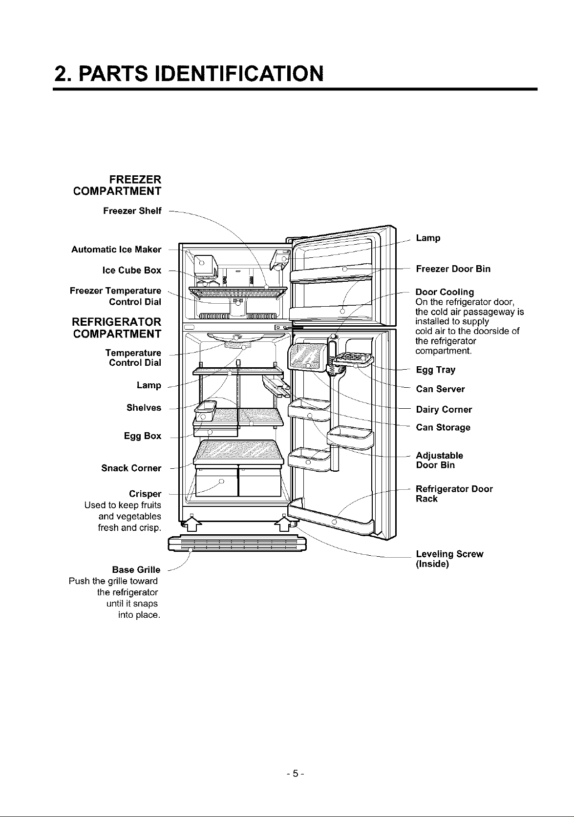
FREEZER
COMPARTMENT
Freezer Shelf
Automatic Ice Maker
Lamp
Ice Cube Box
Freezer Temperature
Control Dial
REFRIGERATOR
COMPARTMENT
Temperature
Control Dial
Lamp
Shelves
Egg Box
Snack Corner
Crisper
Used to keep fruits
and vegetables
fresh and crisp.
Freezer Door Bin
Door Cooling
On the refrigerator door,
the cold air passageway is
installedto supply
cold air to the doorside of
the refrigerator
compartment.
Egg Tray
Can Server
Dairy Corner
Can Storage
Adjustable
Door Bin
Refrigerator Door
Rack
Base Grille
Push the grille toward
the refrigerator
until it snaps
into place.
Leveling Screw
J
-5-
(Inside)
3. DISASSEMBLY
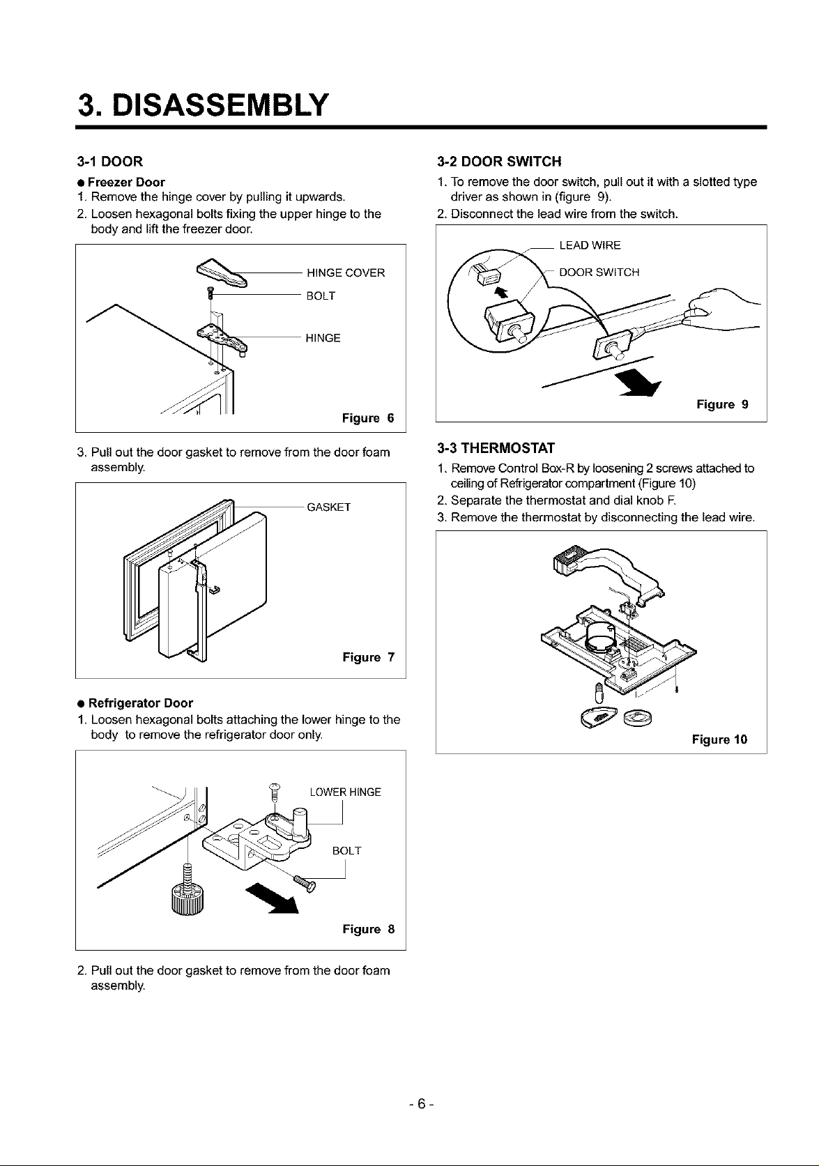
3-1 DOOR
• Freezer Door
1, Remove the hinge cover by pulling it upwards,
2, Loosen hexagonal bolts fixing the upper hinge to the
body and lift the freezer door.
HINGE COVER
HINGE
BOLT
Figure 6
3. Pull out the door gasket to remove from the door foam
assembly.
3-2 DOOR SWITCH
1. To remove the door switch, pull out it with a slotted type
driver as shown in (figure 9),
2, Disconnect the lead wire from the switch.
LEAD WIRE
DOOR SWITCH
Figure 9
3-3 THERMOSTAT
1, Remove Control Box-R by loosening 2screws attached to
coiling of Refrigerator compartment (Figure 10)
2, Separate the thermostat and dial knob R
3, Remove the thermostat by disconnecting the lead wire,
GASKET
Figure 7
• Refrigerator Door
1. Loosen hexagonal bolts attaching the lower hinge to the
body to remove the refrigerator door only.
LOWER HINGE
BOLT
Figure 8
2, Pull out the door gasket to remove from the door foam
assembly.
Figure 10
-6-
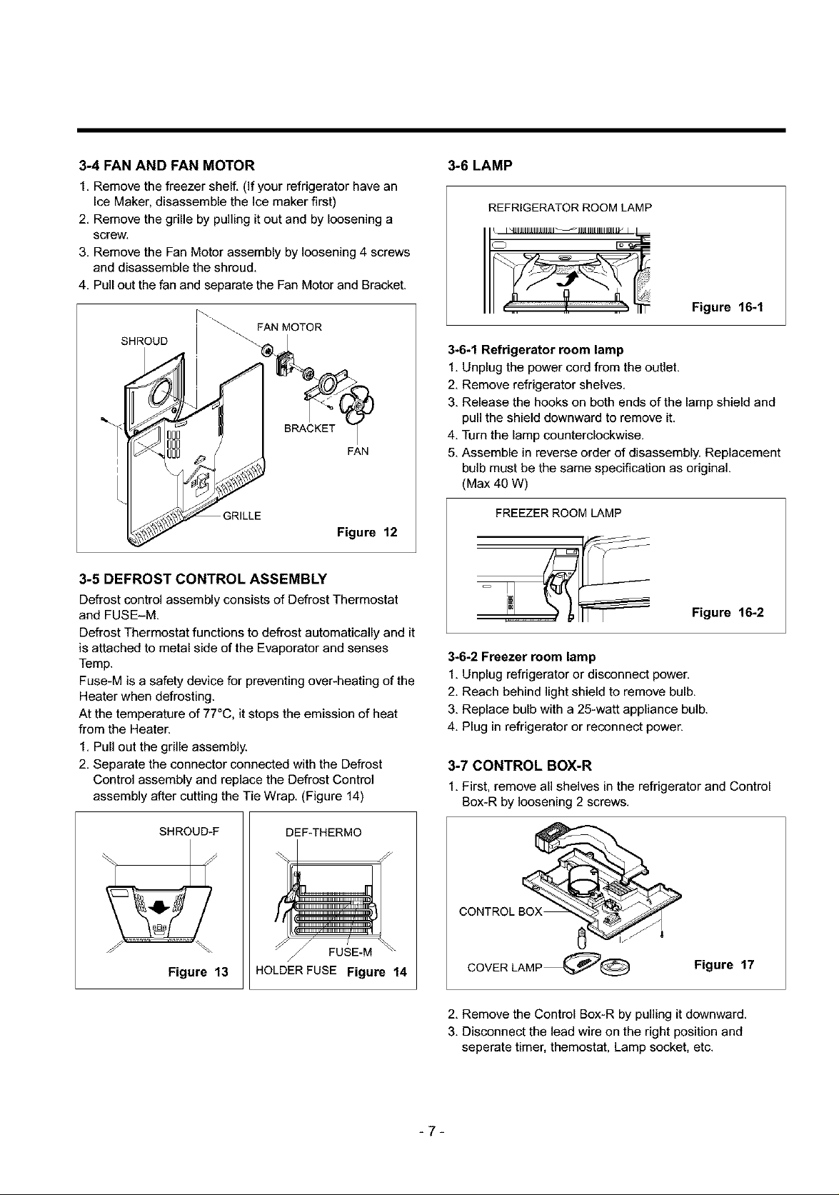
3-4 FAN AND FAN MOTOR
1. Remove the freezer shelf. (If your refrigerator have an
Ice Maker, disassemble the Ice maker first)
2. Remove the grille by pulling it out and by loosening a
screw.
3. Remove the Fan Motor assembly by loosening 4 screws
and disassemble the shroud.
4. Pull out the fan and separate the Fan Motor and Bracket.
SHROUD _'_,FANMOTOR
BRACKET
I
I
3-5 DEFROST CONTROL ASSEMBLY
Defrost control assembly consists of Defrost Thermostat
and FUSE-M
Defrost Thermostat functions to defrost automatically and it
is attached to metal side of the Evaporator and senses
Temp.
Fuse-M is a safety device for preventing over-heating of the
Heater when defrosting.
At the temperature of 77°C, it stops the emission of heat
from the Heater.
1. Pull out the grille assembly.
2. Separate the connector connected with the Defrost
Control assembly and replace the Defrost Control
assembly after cutting the Tie Wrap. (Figure 14)
FAN
Figure 12
3-6 LAMP
REFRIGERATOR ROOM LAMP
Figure 16-1
3-6-1 Refrigerator room lamp
1. Unplug the power cord from the outlet.
2. Remove refrigerator shelves.
3. Release the hooks on both ends of the lamp shield and
pull the shield downward to remove it.
4. Turn the lamp counterclockwise.
5. Assemble in reverse order of disassembly. Replacement
bulb must be the same specification as original.
(Max 40 W)
FREEZER ROOM LAMP
Figure 16-2
3-6-2 Freezer room lamp
1. Unplug refrigerator or disconnect power.
2. Reach behind light shield to remove bulb.
3. Replace bulb with a 25-watt appliance bulb.
4. Plug in refrigerator or reconnect power.
3-7 CONTROL BOX-R
1. First, remove all shelves in the refrigerator and Control
Box-R by loosening 2 screws.
I I
Figure 13 HOLDERFUSE Figure 14
-7-
COVER LAMP_@ Figure 17
2. Remove the Control Box-R by pulling it downward.
3. Disconnect the lead wire on the right position and
seperate timer, themostat, Lamp socket, etc.
&
4. ADJUSTMENT
4-1 COMPRESSOR
4-14 Role
The compressor intakes low temperature and low pressure
gas evaporated from evaporator of the refrigerator, and
condenses this gas to high temperature and high pressure
gas, and then plays delivering role to condenser.
4-1-2 Composition
The compressor includes overload protection. The PTC
starter and OLP (overload protector) are outside the
compressor. Since the compressor is manufactured to
tolerances of 1 micron, and is sealed in a dust - and
moisture - free environment, use extreme caution when
repairing it.
4-%3 Note for Usage
(1) Be careful not to allow over-voltage and over-current.
(2) No Strike
If applying forcible power or strike (dropping or careless
handling), poor operation and noise may occur.
(3) Use proper electric components appropriate to the
Compressor.
(4) Note to Keep Compressor.
If Compressor gets wet in the rain and rust in the pin of
Hermetic Terminal, the result may be poor operation
and poor contact may cause.
(5) Be careful that dust, humidity, and welding flux don't
contaminate the compressor inside when replacing the
Compressor. Dust, humidity, and flux due to welding
which contaminates the cylinder may cause Iockage
and noise.
4-2 PTC-STARTER
4-2-1 Composition of PTC-Starter
(1) PTC (Positive Temperature Coefficient) is a no-contact
semiconductor starting device which uses ceramic
material consisting of BaTiO3.
(2) The higher the temperature is, the higher the resistance
value. These features are used as starting device for
the Motor.
4-2-2 Role of PTC-Starter
(1) PTC is attached to Hermetic Compressor used for
Refrigerator, Show Case, and starting Motor.
(2) Compressor for household refrigerator applies to
single-phase induction Motor.
For normal operation of the single-phase induction
motor, in the starting operation flows in both main coil
and sub-coil. After the starting is over, the current in
subcoil is cut off. The proper features of PTC play all
the above roles. So, PTC is used as a motor starting
device.
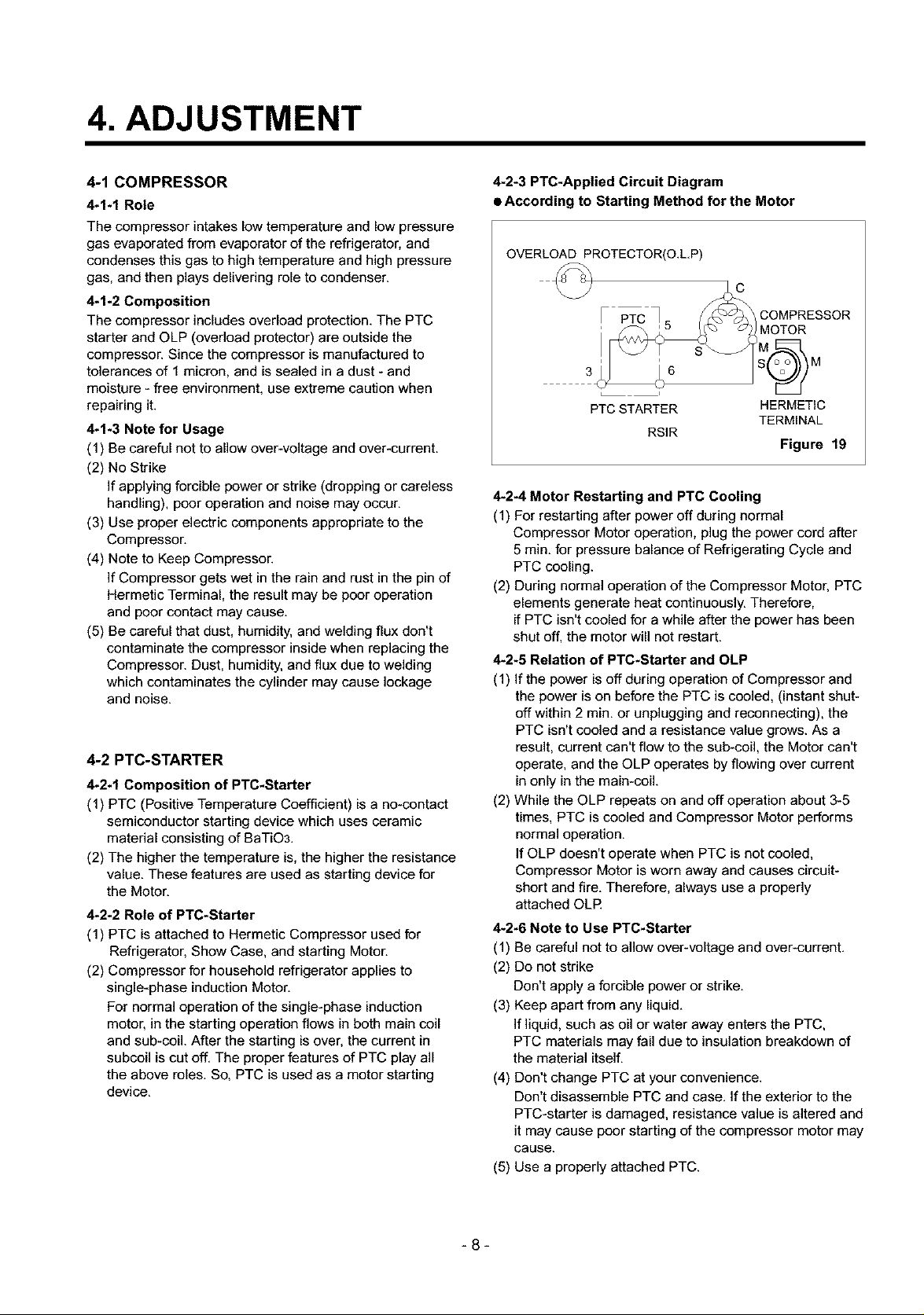
4-2-3 PTC-Applied Circuit Diagram
• According to Starting Method for the Motor
OVERLOAD PROTECTOR(O.L.P)
PTC _ < _-_a_ COMPRESSOR
PTC STARTER HERMETIC
RSlR
4-2-4 Motor Restarting and PTC Cooling
(1) For restarting after power off during normal
Compressor Motor operation, plug the power cord after
5 min. for pressure balance of Refrigerating Cycle and
PTC cooling.
(2) During normal operation of the Compressor Motor, PTC
elements generate heat continuously. Therefore,
if PTC isn't cooled for a while after the power has been
shut off, the motor will not restart.
4-2-5 Relation of PTC-Starter and OLP
(1) If the power is off during operation of Compressor and
the power is on before the PTC is cooled, (instant shut-
off within 2 rain. or unplugging and reconnecting), the
PTC isn't cooled and a resistance value grows. As a
result, current can't flow to the sub-coil, the Motor can't
operate, and the OLP operates by flowing over current
in only in the main-coil.
(2) While the OLP repeats on and off operation about 3-5
times, PTC is cooled and Compressor Motor performs
normal operation.
If OLP doesn't operate when PTC is not cooled,
Compressor Motor is worn away and causes circuit-
short and fire. Therefore, always use a properly
attached OLR
4-2-6 Note to Use PTC-Starter
(1) Be careful not to allow over-voltage and over-current,
(2) Do not strike
Don't apply a forcible power or strike,
(3) Keep apart from any liquid,
if liquid, such as oil or water away enters the PTC,
PTC materials may fail due to insulation breakdown of
the material itself,
(4) Don't change PTC at your convenience,
Don't disassemble PTC and case, If the exterior to the
PTC-starter is damaged, resistance value is altered and
it may cause poor starting of the compressor motor may
cause.
(5) Use a properly attached PTC.
TERMINAL
Figure 19
-8-
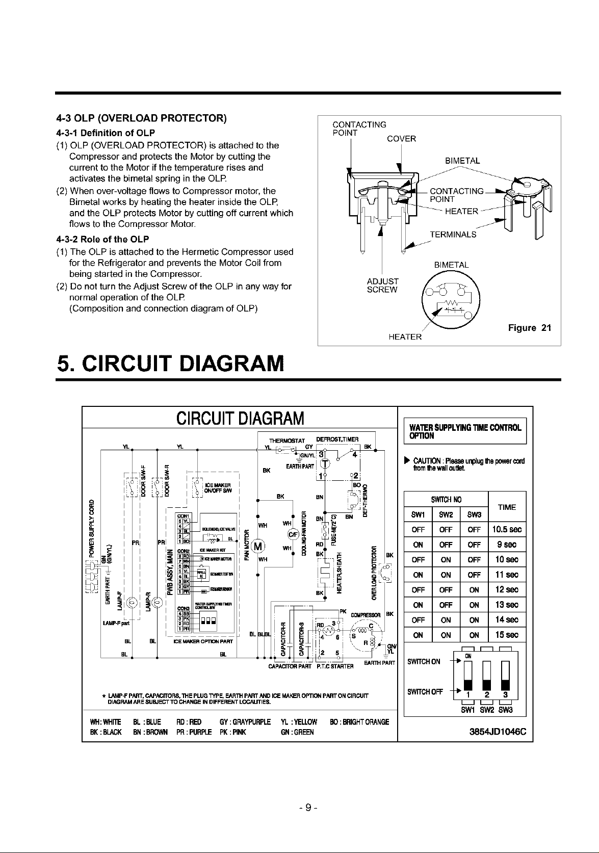
4-30LP (OVERLOAD PROTECTOR)
4-3-1 Definition of OLP
(1) OLP (OVERLOAD PROTECTOR) is attached to the
Compressor and protects the Motor by cutting the
current to the Motor if the temperature rises and
activates the bimetal spring in the OLR
(2) When over-voltage flows to Compressor motor, the
Bimetal works by heating the heater inside the OLP,
and the OLP protects Motor by cutting off current which
flows to the Compressor Motor.
4-3-2 Role of the OLP
(1) The OLP is attached to the Hermetic Compressor used
for the Refrigerator and prevents the Motor Coil from
being started in the Compressor,
(2) Do not turn the Adjust Screw of the OLP in any way for
normal operation of the OLR
(Composition and connection diagram of OLP)
CONTACTING
POINT
l TERMINALS - I./I
ADJUST
SCREW
COVER
BIMETAL
ONTACT,NG
q PO,NT I
BIMETAL
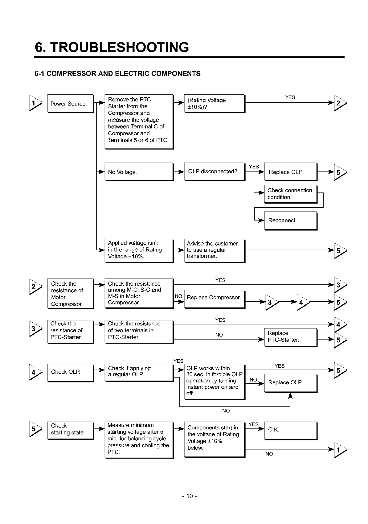
5. CIRCUIT DIAGRAM
CIRCUITDIAGRAM
"IL YL
I i iICEMAKER
CC
ICE Mi_R O_ pART
BL
_ERMQ6TAT DEFRO6T,TIMER
CAPACITORPART P.T.CSTARTER
E&R3H pART
HEATER
WAI_RSUPPLYING11MECONTROLI
OPllON
I_ CAUTION:PleaseunplugIllepowercord
fromIhewallcuret.
Figure 21
1
]
TIME
10.5sec
9sec
10sec
11sec
12sec
13sec
14sec
15sec
* I.AMP-F PART,CAPACITORS,IH E PLUGl_fPE, F._R_'I PART AND ICE MAI_R OPTION PART ON CIRCUIT
DIAGRAM ARE SUBJECT TO CHAN_E IN DIFFERENT LOCALITIES.
WH:WHI'_ BL:BLUE RD:RED GY:GRAYPURPLEYL:YELLOW BO:BRIGHTORANGE
BK:BLACK BN:BROWN PR:PURPLE PK:PINK GN:GREEN
-9-
' C"ONIi;;
SWITCHOFF 2 3
SWI SW2SW3
3854JD1046C
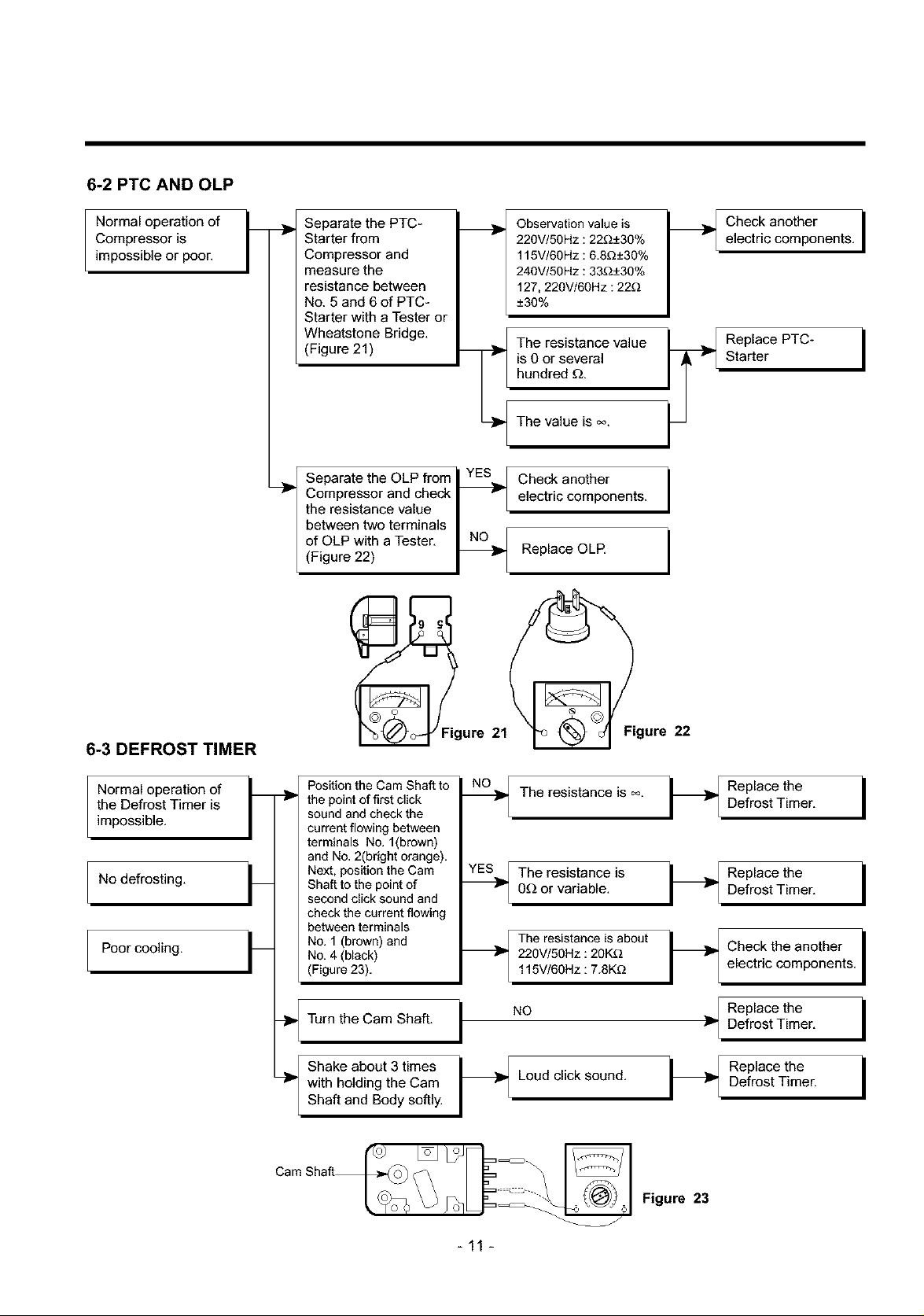
6. TROUBLESHOOTING
6-1 COMPRESSOR AND ELECTRIC COMPONENTS
Power Source.
Check the
resistance of
Motor
Compressor,
__ Remove the PTC-
Starter from the
Compressor and
measure the voltage
between Terminal C of
Compressor and
Terminals 5 or 6 of PTC.
_1 Applied voltage isn't
in the range of Rating
Voltage +10%.
among M-C, S-C and
M-S in Motor
. heck the resistance
Compressor,
_,Y (Rating Voltage+_10%)? i YES __[_
-_OLP disconnected?
Replace OLR _-_
C°hed_kic°nnecti° n _1
Recon0ect.I
to use a regular
Advise the customer i _-[_
transformer.
Replace Compressor.
N_O YES }__
Check the
resistance of
PTC-Starter.
Check OLR
Check
starting state,
of two terminals in
F heck the resistance i
PTC-Starter,
YES
b Check if applying I_OLP works within i YES _- [_a regular OLR L 30 sec, in forcible OLP I r
I I operation byturning _ Replace OLR i
Hinstant power on and _ r
starting voltage after 5
rain. for balancing cycle
pressure and cooling the
b easure minimum
PTC.
the voltage of Rating
Voltage +_10%
Components start in p O.K. i
below. NO _' [_
YES
NO _'- Replace
NO
-10-
PTC-Starter.
6-2 PTC AND OLP
Normal operation of [__ __
Compressor is
impossible or poor.
/
Separate the PTC-
Starter from
Compressor and
measure the
resistance between
No. 5 and 6 of PTC-
Starter with a Tester or
Wheatstone Bridge,
(Figure 21)
_' Compressor and check I v
the resistance value
between two terminals ..._
ofOLPwith aTester, I NO
I Separate the OLP from YE_
(Figure 22) _1 -
Observation value is
220V/50Hz : 22£2+_30%
115V/60Hz : 6.8D+_30%
240V/50Hz : 33£2+_30%
127, 220V/60Hz : 22_2
+_30%
The resistance value
is 0 or several
hundred £2.
The value is oo
Check another
electric components,
Replace OLR
Check another ielectric components,
Replace PTC-
Starter
i
6-3 DEFROST TIMER
Normal operation of
the Defrost Timer is
impossible,
No defrosting,
Poor cooling,
(_gure
Position the Cam Shaft to
the point of first click
sound and check the
current flowing between
terminals No. 1(brown)
and No. 2(bright orange).
Next, position the Cam
Shaft to the point of
second click sound and
check the current flowing
between terminals
No. 1 (brown) and
i
No. 4 (black)
(Figure 23).
Turn the Cam Shaft. I
with holding the Cam
i Shake about 3 times b
Shaft and Body softly.
i
21 _igure
The resistance is =. i_ I
0£2or variable,
The resistance is _._
220V/50Hz : 20K_
The resistance is about H
115V/60Hz: 7.8K_
NO _'
Loud click sound,
22
Replace the
Defrost Timer,
Replace the
Defrost Timer,
Check the another
electric components,
Replace the
Defrost Timer,
Replace the
Defrost Timer.
i
i
i
i
i
CamShaft__ ]_Jk'_: __
-11 -
F, ,,re
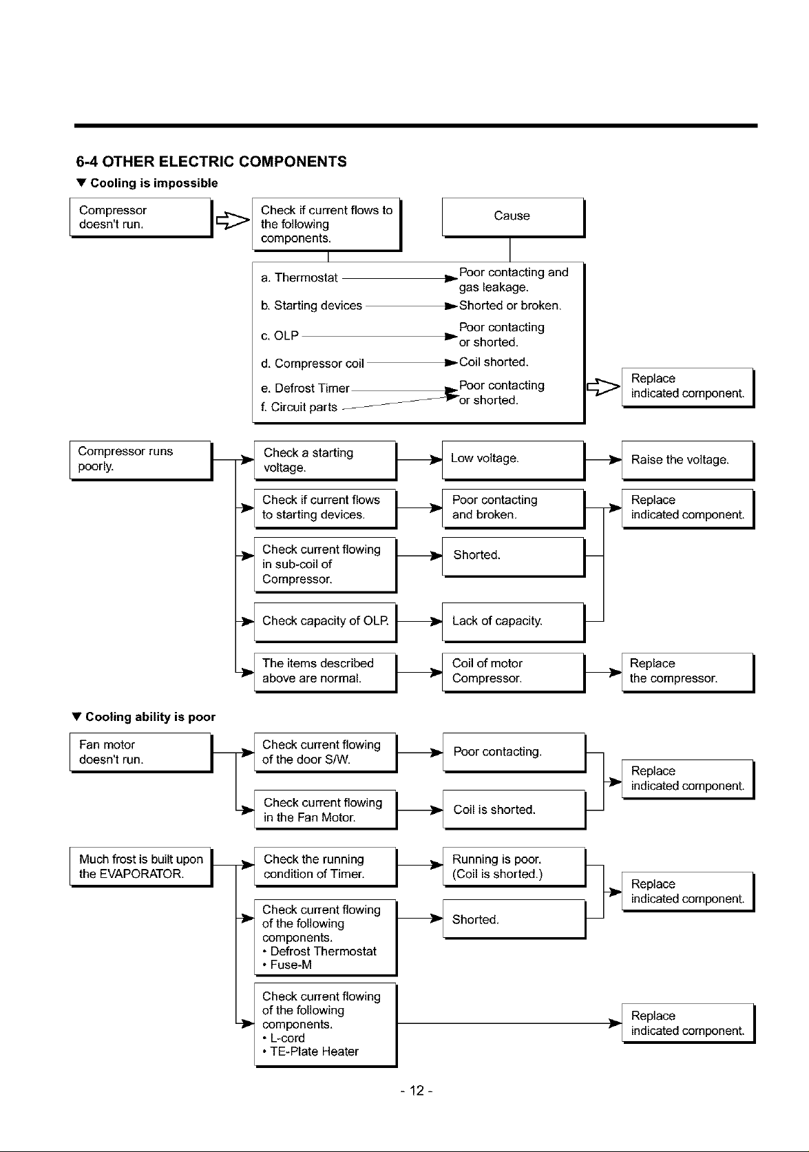
6-4 OTHER ELECTRIC COMPONENTS
• Cooling is impossible
doesn't run. the following
CompressorI Check,,current,,owstoi Cause
components.i I
a. Thermostat
b. Starting devices
c. OLP _' or shorted.
d. Compressor coil
e. Defrost Timer ,._ Poor contacting
f. Circuit parts
_or shorted.
Poor contacting and
"- gas leakage.
Shorted or broken.
Poor contacting
Coil shorted.
=;:>
indicated component.
Replace i
Compressor runs
poorly.
• Cooling ability is poor
Fan motor
doesn't run.
Check a starting Low voltage.
voltage.
to starting devices, and broken.
Check if current flows Poor contacting _
Check current flowing Shorted. L
in sub-coil of
Compressor,
Check capacity of OLE
The items described
above are normal.
Check current flowing
of the door S/W.
Check current flowing
in the Fan Motor.
P
Lack of capacity. _--
Compressor.
Coil of motor
Poor contacting. _--_
Coil is shorted. _--
I -
/
Raise the voltage.
Replace
indicated component.
the compressor,
Replace i
indicated component.
Replace i
i
i
Much frost is built upon
the EVAPORATOR.
Check the running
condition of Timer.
Check current flowing
of the following
components,
• Defrost Thermostat
• Fuse-M
of the following
components,
• L-cord
Check current flowing
• TE-Plate Heater
Running is poor, ____(Coil is shorted.)
Replace iindicated component.
Shorted. _--
Replace
indicated component.
-12-
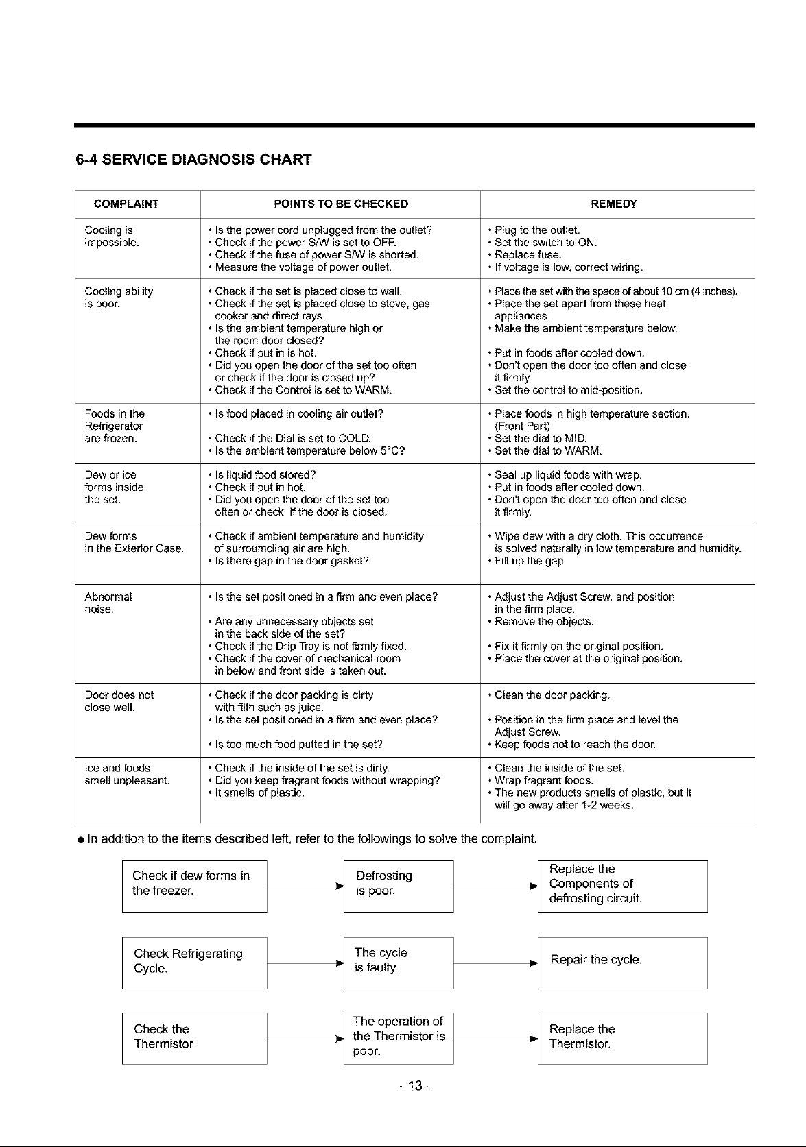
6-4 SERVICE DIAGNOSIS CHART
COMPLAINT POINTS TO BE CHECKED REMEDY
Cooling is • Is the power cord unplugged from the outlet? * Plug to the outlet.
impossible. • Check if the power S/W is set to OFF. * Set the switch to ON.
• Check if the fuse of power S/W is shorted. * Replace fuse.
• Measure the voltage of power outlet. * If voltage is low, correct wiring.
Cooling ability
is poor.
Foods in the • Is food placed in cooling air outlet? * Place foods in high temperature section.
Refrigerator (Front Part)
are frozen. • Check if the Dial is set to COLD. * Set the dial to MID.
Dew or ice • Is liquid food stored? * Seal up liquid foods with wrap.
forms inside • Check if put in hot. * Put in foods after cooled down.
the set. • Did you open the door of the set too * Don't open the door too often and close
Dew forms • Check if ambient temperature and humidity *Wipe dew with a dry cloth. This occurrence
in the Exterior Case. of surroumcling air are high. is solved naturally in low temperature and humidity.
Abnormal • Is the set positioned in a firm and even place? *Adjust the Adjust Screw, and position
noise, in the firm place.
• Check if the set is placed close to wall.
• Check if the set is placed close to stove, gas
cooker and direct rays.
• Is the ambient temperature high or
the room door closed?
• Check if put in is hot.
• Did you open the door of the set too often
or check if the door is closed up?
• Check if the Control is set to WARM.
• Is the ambient temperature below 5°C? * Set the dial to WARM.
often or check if the door is closed, it firmly.
• Is there gap in the door gasket? * Fill up the gap.
• Are any unnecessary objects set * Remove the objects.
in the back side of the set?
• Check if the Drip Tray is not firmly fixed. * Fix it firmly on the original position.
• Check if the cover of mechanical room * Place the cover at the original position.
in below and front side is taken out.
• Place the set w_ the space of about 10 cm (4 inches).
• Place the set apart from these heat
appliances.
• Make the ambient temperature below.
• Put in foods after cooled down.
• Don't open the door too often and close
it firmly.
• Set the control to mid-position.
Door does not • Check if the door packing is dirty * Clean the door packing.
close well. with filth such as juice.
Ice and foods • Check if the inside of the set is dirty. * Clean the inside of the set.
smell unpleasant. • Did you keep fragrant foods without wrapping? *Wrap fragrant foods.
• In addition to the items described left, refer to the followings to solve the complaint.
Check if dew forms in
the freezer,
Check Refrigerating Repair the cycle,
Cycle,
Check the Replace the
Thermistor Thermistor,
• Is the set positioned in a firm and even place? * Position in the firm place and level the
• Is too much food putted in the set? * Keep foods not to reach the door.
• It smells of plastic. *The new products smells of plastic, but it
Adjust Screw.
will go away after 1-2 weeks.
Replace the
_" is poor.
Defrosting
Components of
defrosting circuit.
The cycle
is faulty.
_, the Thermistor is
The operation of
poor,
-13-
 Loading...