

LG LRTPC2031BS, LRTPC1831BS Owner’s Manual
2001.06.01160/120
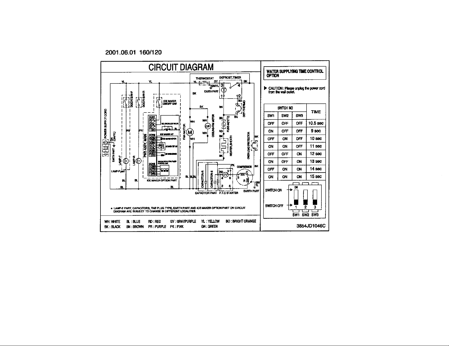
CIRCUITDIAGRAM
..... BK _:
'[_j_L_==_,i_v_=-
I; :1 I : :Oit_FSN4
ili / iv:----
i _,,
.
CAPACrlORpARTp,T.GFCrARTF.FI
_r LAMP.FpART,CAP.kG/TORS,"IHEPLUG"_pE, F._RTHpARTANDICEMAKEROPTK_ pARTONC_RCUIT
_/,_q_M AREELle,._-CTTOCHANGIEIN Dir'FIERENTLOCALJTI_.
WH:'611ffE BL :BLUE RD:RED Qy:(]RAYPtIRP!,_ YL:YB.LOW BO:BRIQHT(_._GE
EK:BLACK BN:BROWN PR:PUflF1.E PK:PINK GN;GRE_N
WA'i-r.flSUPPLYING11MECON'mOL
OPTIOH
CAUTION:Rme Lm#ugthepowerc_l
h_nIhew_iO_L
SWff_ NO
8W1 6W3
OFF OFF 10.5 S_
ON OFF 9 860
BK
OFF OFF 10 se(
I
ON OFF 11 se(
OFF ON 12se(
ON ON 13se(
BK
OFF ON 14 se(
r
pART
S_I_'I OFF
$Wl S_t2 S_t3
TIME
15se(
3854JD1046C
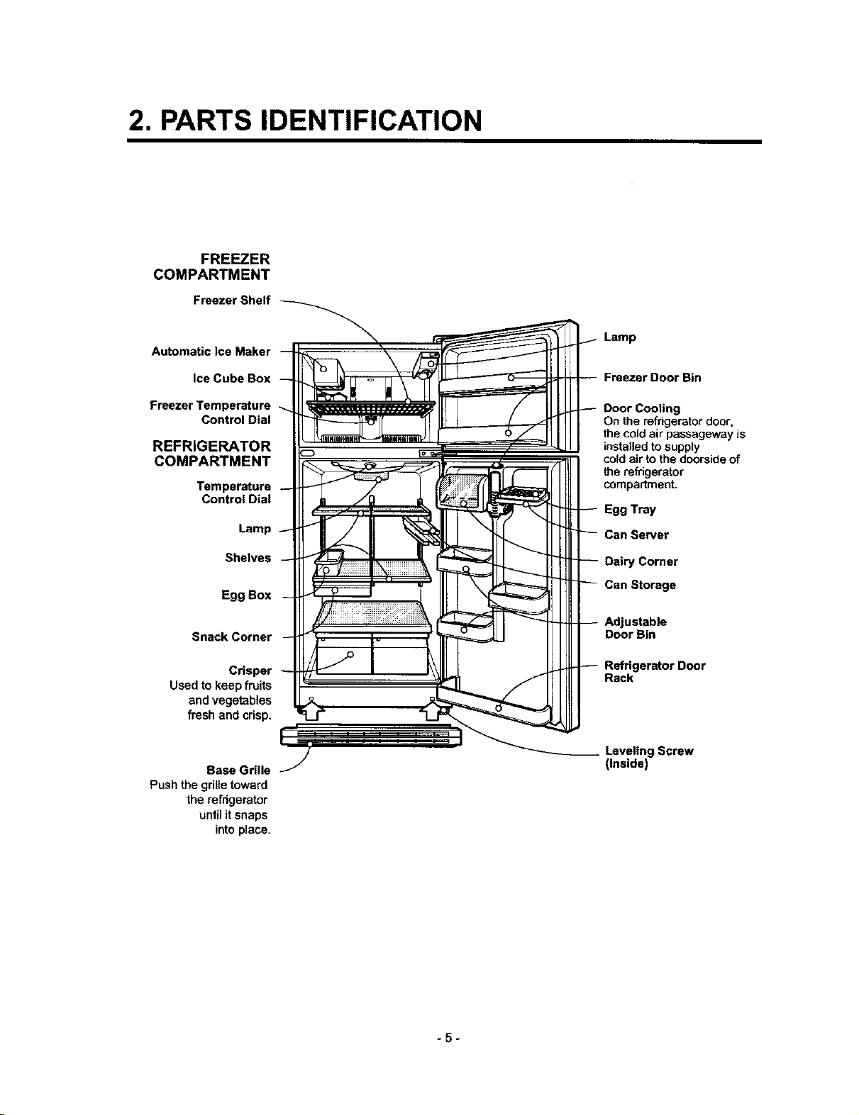
2. PARTS IDENTIFICATION
FREEZER
COMPARTMENT
Freezer Shelf
Automatic Ice Maker
Ice Cube Box
Freezer Temperature
Control Dial
REFRIGERATOR
COMPARTMENT
Temperature
Control Dial
Lamp
Shelves
Egg Box
Snack Corner
Crisper
Used to keepfruits
and vegetables
fresh and crisp.
Lamp
Freezer Door Bin
Door Cooling
On the refrigerator door,
the cold air passageway is
installedto supply
coldair tothe doorsideof
the refrigerator
compartment.
Egg Tray
Can Server
Dairy Comer
Can Storage
Adjustable
Door Bin
Refrigerator Door
Rack
Base Grille
Push the grille toward
the refrigerator
until it snaps
into place.
Leveling Screw
(Inside)
-5-
3. DISASSEMBLY
34 DOOR
• Freezer Door
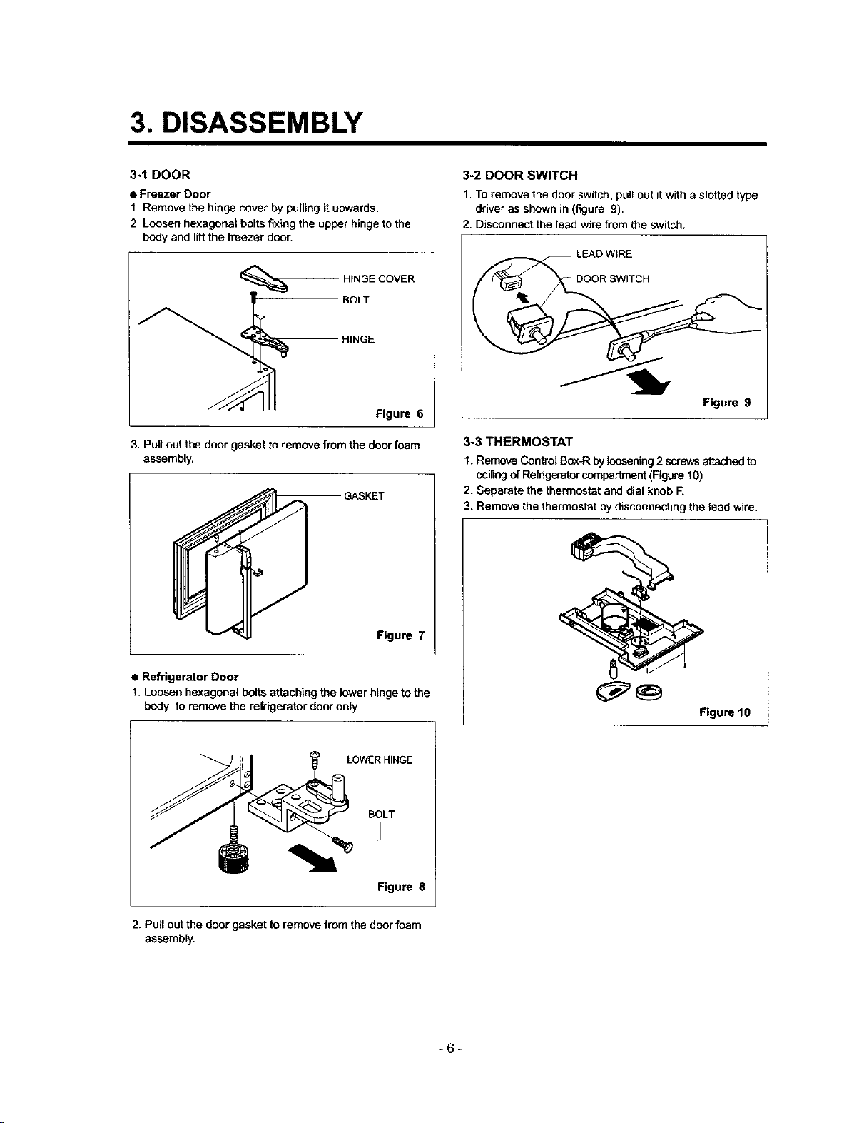
1. Remove the hinge cover by pulling it upward&
2 Loosen hexagonal bolts fixing the upper hinge to the
body and lift the freezer door.
BOLT
HINGE
HINGE COVER
Figure 6
3. Pull out the door gasket to remove from the door foam
assembly.
GASKET
3-2 DOOR SWITCH
1. To remove the door switch, pull out it with a slotted type
driver as shown in (figure 9).
2. Disconnect the lead wire from the switch.
LEAD WIRE
DOOR SWITCH
Figure 9
3-3 THERMOSTAT
1. Remove Control BoxJRby loosening2 screws attached to
ceiling of Refrigeratorcompartment (Figure 10)
2. Separate the thermostat and dial knob F.
3. Remove the thermostat by disconnecting the lead wire.
Figure 7
• Refrigerator Door
I. Loosen hexagonal bolts attaching the lower hinge to the
body to remove the refrigerator door only.
LOWER HINGE
BOLT
__1
Figure 8
2. Pull out the door gasket to remove from the door foam
assembly.
Figure 10
-6-
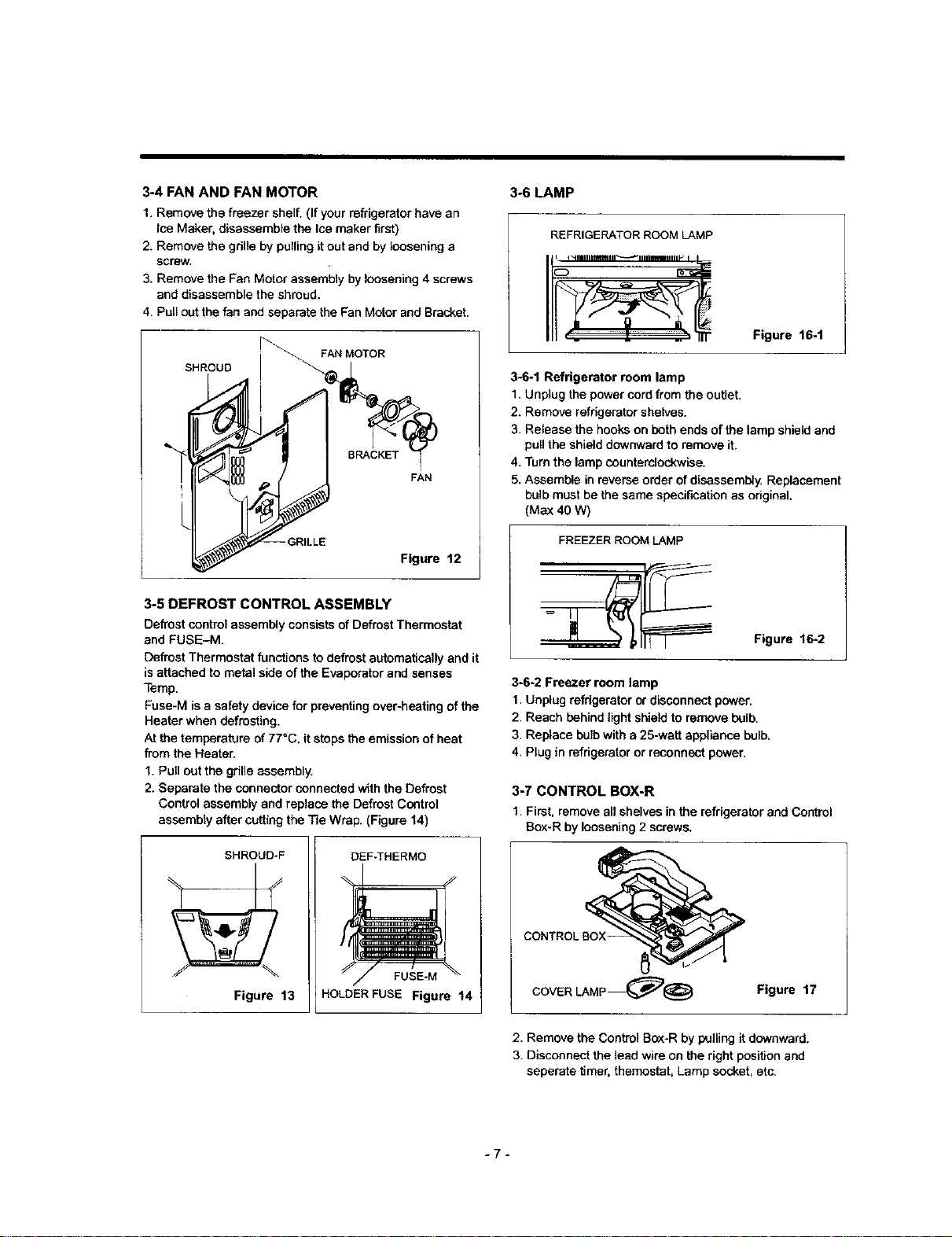
3-4 FAN AND FAN MOTOR
1. Remove the freezer shelf. (If your refrigerator have an
Ice Maker, disassemble the Ice maker first)
2. Remove the grille by pulling itout end by loosening a
screw.
3. Remove the Fan Motor assembly by loosening 4 screws
and disassemble the shroud.
4. Pull out the fan and separate the Fan Motor and Bracket.
3°6 LAMP
REFRIGERATOR ROOM LAMP
f_ ...v°£_ -
Figure 16-t
SHROUD
q
Figure 12
3-5 DEFROST CONTROL ASSEMBLY
Defrost control assembly consists of Defrost Thermostat
and FUSE--M.
Defrost Thermostat functions to defrost automatically and it
is attached to metal side of the Evaporator and senses
Temp.
Fuse-M is a safety device for preventing over-heating of the
Heater when defrosting.
At the temperature of 77=C, it stops the emission of heat
from the Heater.
I. Pull out the grille assembly.
2. Separate the connector connected with the Defrost
Control assembly and replace the Defrost Control
assembly after cutting the Tie Wrap. (Figure 14)
SHROUD-F
DEF-THERMO
3-6-1 Refrigerator room lamp
1. Unplug the power cord from the outlet.
2. Remove refrigerator shelves.
3. Release the hooks on both ends of the lamp shield and
pull the shield downward to remove it.
4. Turn the lamp countemlockwise.
5. Assemble in reverse order of disassembly. Replacement
bulb must be the same specification as original.
(Max 40 W)
FREEZER ROOM LAMP
Figure 16-2
3-6-2 Freezer room lamp
1. Unplug refrigerator or disconnect power.
2. Reach behind light shield to remove bulb.
3. Replace bulb with a 25-watt appliance bulb,
4. Plug in refrigerator or reconnect power.
3-7 CONTROL BOX-R
1. First, remove all shelves in the refrigerator and Control
Bax-R by loosening 2 screws.
Figure 13
FUSE-M
HOLDER FUSE Figure 14
J
COVER LAMP_@ Figure 17
2. Remove the Control Bax-R by pulling it downward,
3. Disconnect the lead wire on the right position and
seperete timer, themostat, Lamp socket, eto,
-7-
4. ADJUSTMENT
44 COMPRESSOR
4-1-1 Role
The compressor intakes low temperature and low pressure
gas evaporated from evaporator of the refrigerator, and
condenses this gas to high temperature and high pressure
gas, and then plays delivering role to condenser.
4-1-2 Composition
The compressor includes overload protection. The PTC
starter and OLP (overload protector) are outside the
compressor. Since the compressor is manufactured to
tolerances of 1 micron, and is sealed in a dust - and
moisture - free environment, use extreme caution when
repairing it.
4-1-3 Note for Usage
(1) Be careful not to allow over-voltage and over-current.
(2) No Strike
If applying forcible bower or strike (dropping or careless
handling), poor operation and noise may occur.
{3) Use proper electric components appropriate to the
Compressor.
(4) Note to Keep Compressor.
If Compressor gets wet in the rain and rust in the pin of
Hermetic Terminal, the result may be poor operation
and poor contact may cause.
(5) Be careful that dust, humidity, and welding flux don't
contaminate the compressor inside when replacing the
Compressor. Dust, humidity, and flux due to welding
which contaminates the cylinder may cause leakage
and noise.
4-2 PTC-STARTER
4-2-1 Composition of PTC-Starter
(1) PTC (Positive Temperature Coefficient) is a no-contact
semiconductor starting device whioh uses ceramic
material consisting of BaTiO3.
(2) The higher the temperature is, the higher the resistance
value. These features are used as starting device for
the Motor.
4-2-2 Role of PTC-Starter
(1) PTC is attached to Hermetic Compressor used for
Refrigerator, Show Case, and startthg Motor.
(2) Compressor for household refrigerator applies to
single-phase induction Motor.
For normal operation of the single-phase induction
motor, in the starting operation flows in both main coil
and sub-coil. After the starting is over, the current in
suboeil is cut off. The proper features of PTC play all
the above roles. So, PTC is used as a motor starting
device.
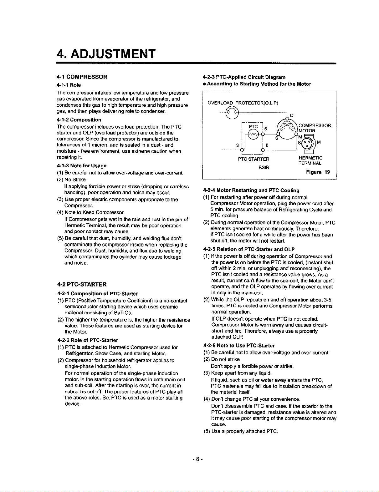
4-2-3 PTC-Applied Circuit Diagram
• According to Starting Method for the Motor
OVERLOAD PROTECTOR(O.L.P)
@ o
og; E SOR
PTC STARTER HERMETIC
RSIR
4-2-4 Motor Restarting and PTC Cooling
(1) For restarting after power off during normal
Compressor Motor operation, plug the power cord after
5 min. for pressure balance of Refrigerating Cycle and
PTC cooling.
(2) During normal operation of the Compressor Motor, PTC
elements generate beat continuously. Therefore,
if PTC isn't cooled for a while after the power has been
shot off, the motor will not restart.
4-2_5 Relation of PTC-Starter and OLP
(1) If the power is off during operation of Compressor and
the bower is on before the PTC is cooled, (instant shut-
off within 2 min. or unplugging and reconnecting), the
PTC isn't cooled and a resistance value grows. As a
result, current can't flow to the sub-coiL the Motor can't
operate, and the OLP operates by flowing over currant
in only in the main-coil.
(2) While the OLP repeats on and off operation about 3-5
times, PTC is cooled and Compressor Motor performs
normal operation.
If OLP doesn't operate when PTC is not cooled,
Compressor Motor is worn away and causes circuit-
short and fire. Therefore, always use a properly
attached OLE
4-2-6 Note to Use PTC-Starter
(1) Be careful not to allow over-volfage and over-current.
(2) Do not strike
Don't apply a forcible power or strike.
(3) Keep apart from any liquid.
If liquid, such as oil or water away enters the PTC,
PTC materials may fail due to insulation breakdown of
the material itself.
(4) Don't change PTC at your convenience.
Don't disassemble PTC and case. If the exterior to the
PTC-starter is damaged, resistance value is altered and
it may cause poor starting of the compressor motor may
cause.
(5) Use a properly attached PTC.
TERMINAL
Figure 19
-8-
4-30LP (OVERLOAD PROTECTOR)
4-3-1 Definition of OLP
(1) OLP (OVERLOAD PROTECTOR) is attached to the
Compressor and protects the Motor by cutting the
current to the Motor ifthe temperature dsas and
activates the bimetal spring in the OLF_
(2) When over-voltage flows to Compressor motor, the
Bimetal works by heating the heater inside the OLP,
and the OLP protects Motor by cutting off current which
flows to the Compressor Motor=
4-3-2 Role of the OLP
(1) The OLP is attached to the Hermetic Compressor used
for the Refrigerator and prevents the Motor Coil from
being started in the Compressor.
(2) Do not turn the Adjust Screw ofthe OLP in any way for
normal operation of the OLR
(Composition and connection diagram of OLP)
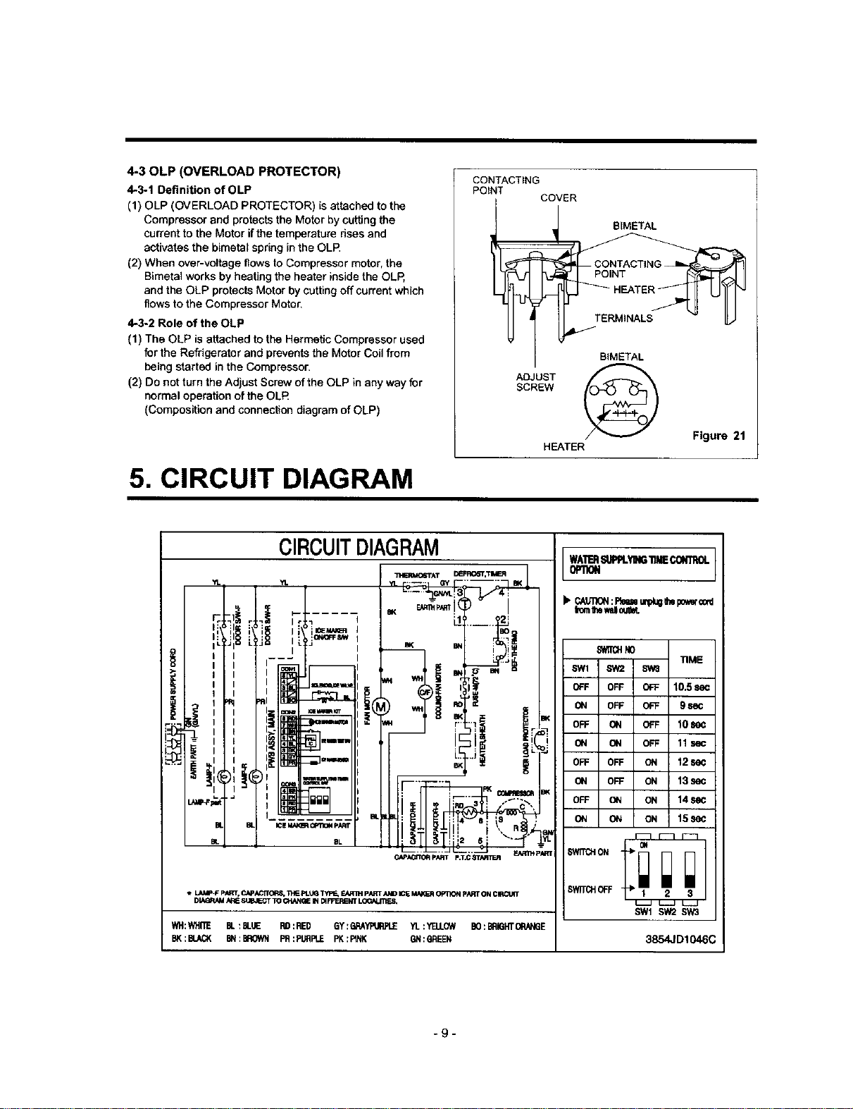
5. CIRCUIT DIAGRAM
CONTACTING
POINT
SCREW
ADJUST
COVER BIMETAL
BIMETAL
HEATER
Figure 21
CIRCUITDIAGRAM
• L , _ -- GY " EK
THEI_Io6"rA'r DL_R,06_,_
' --it ,[\j , ., _ _L_i
' ' , "] ,
I I =_ i i
' l l lI_ (_I 1,
.... I I
- II I i l '_"S .... _-,
• LAV_-F pAR_, C_pi_'C_B, _ pt.U_ "[yp_ FJ_R_-I pi_T i_ID ICE MA_.A _ p.q_T ON ClIRCUtT
DI_IRN_I ARESt,_I_'T TO CHANGE_ _ FP'ER_NTLOON.iTIES,
WH:WHITE BL:BUIE R9:RED 6Y:6RAYPURPLE_L :_Td.LOWBO:BRIGHTORN_GE
BK:BU_( BN:BROWNPR:PIJflPLEPK:FtNK 8N:GREEN
I I_ ! '
CAPid_'TOI_ pART p:r,C _W/d_TER _P_ P/_r
WATERSUPPLYING"flMECONTROL
!b CAU111_I:Re=emplugIt_po_r o0d
from'_ewsll0ulbt.
_N0
SW1 SW2 Sw8
OFF OFF OFF 10.5 se¢
ON OFF OFF 9 se¢
OFF ON OFF 10SeC
ON ON OFF 11sec
OFF OFF ON 12se¢
ON OFF ON 13sec
OFF ON ON 14See
ON ON ON 15See
SWITCHOFF • 2 3
SW1 SW2SW3
_IME
3854JD1046C
-9-
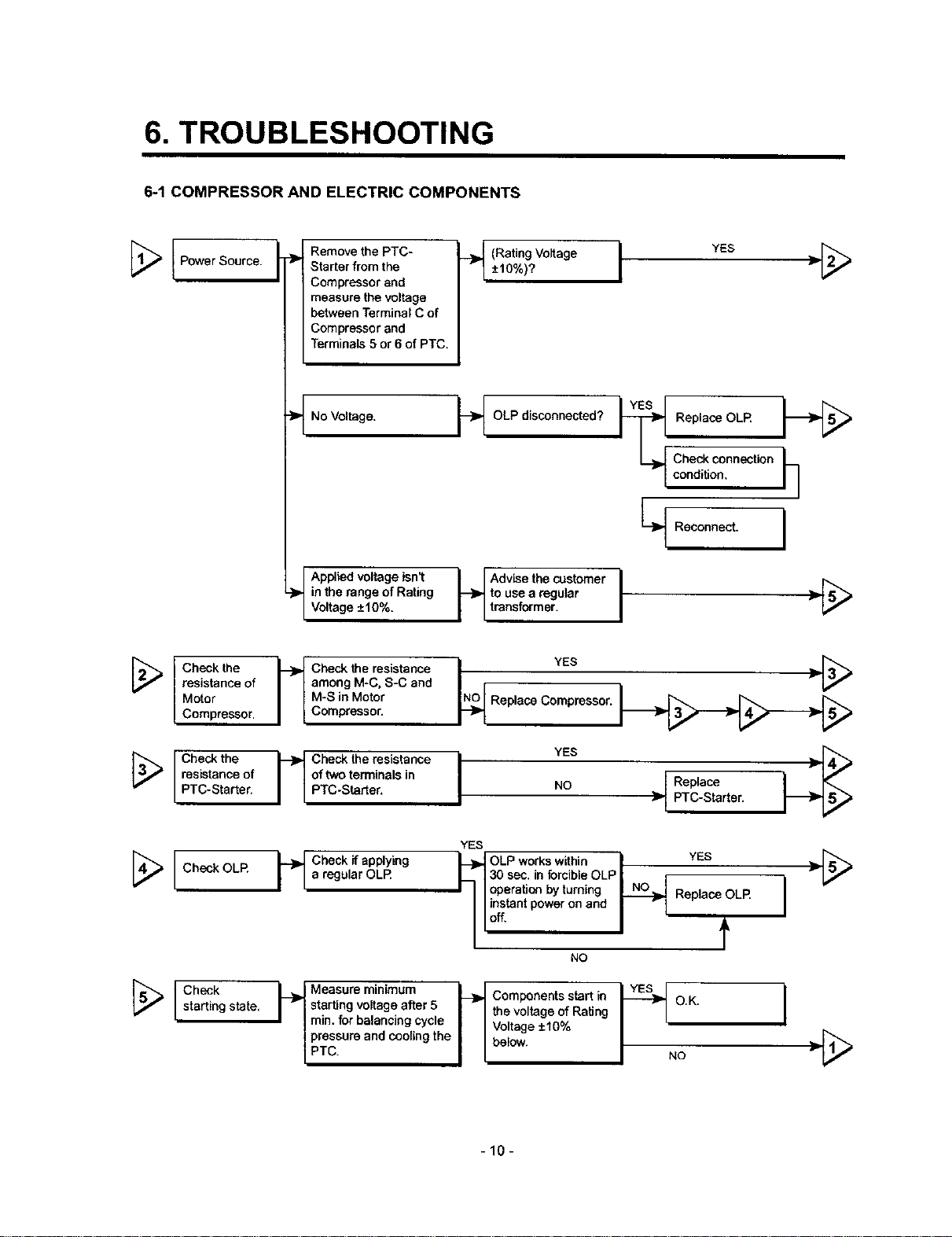
6. TROUBLESHOOTING
6-1 COMPRESSOR AND ELECTRIC COMPONENTS
Remove the PTC-
;_ Power Source.
-_ Starter from the
Compressor and
measure the voltage
between Terminal C of
Compressor and
Terminals 5 or 6 of PTC.
.__ (Rating Voltage YES
±10%)? I "_
No Voltage.
Applied voltage isn't
in the range of Rating
Voltage ±10%.
Check the _--_ Check the resistance
resistance of I I among M-C. S-C and
Motor I I M-S in Motor
Compressor. I L Compressor.
Check the
resistance of
PTC-Starter.
---_ heck the resistance
of two terminals in
PTC-Star[er.
Replace OLR
OLP disconnected?
to use a regular __
_ Advise the customer j [_
transformer.
NNN_OOOReplace CoYm_eesor. _
YES
NO _' PTC-Starter.
YES
Check connection
condition.
Recenne_.
Replace
h
I
[_ I check OLR _'_ check if applying _,l_ OLP w°rks within',30 sec. in forcible OLP, , YES ,[_
I l a regular OLR
I I I operation by turning _ Replace OLR I
I -'
NO
starting state. I r I starting voltage after 5 I I the voltage of Rating
_ Icheck _ Measura minimum I_ Components start io I_ O.K"
I I min. for balancing cycle I I Voltage +-10%
|| PTc.pressureand cooling the i i below. I NO
-10-
I
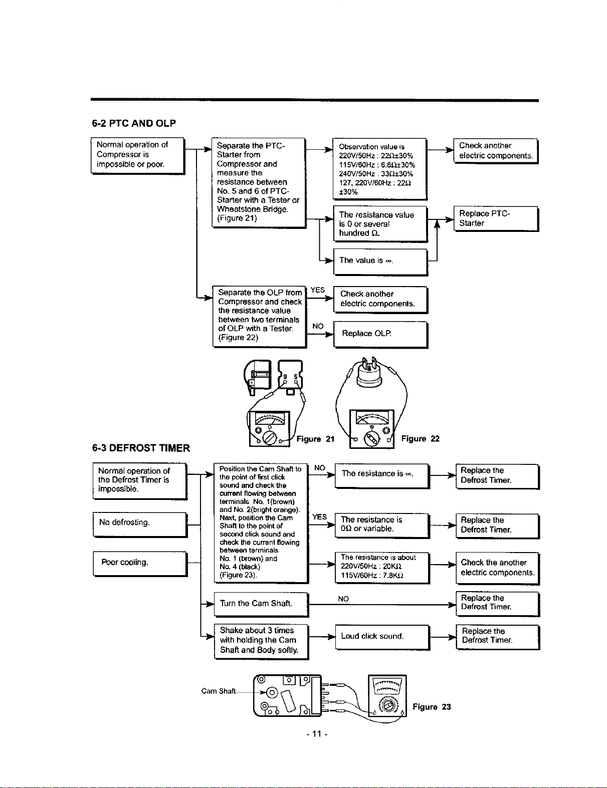
6-2 PTC AND OLP
Normal operation of
Compressor is
impossible or poor.
_}_ Separate the PTC-
Starter from
Compressor and
measure the
resistance between
No. 5 and 6 of PTC-
Starter with a Tester or
(Figure 21)
r
I
Observation value is _l
220V/50Hz :22{2±30%
115V/60Hz :6.8_.2±30%
240V/5OHz : 33_;2_30%
127, 220V/6OHz : 22_
:T:30%
The resistance value _1
is 0 or several
hundred _.
/
-!
/
Check another I
electric components. I
Starter
Replace PTC- I
6-3 DEFROST TIMER
Normal operation of
the Defrost Timer is
impossible.
No defrosting.
Poor cooling.
Wheatstooe Bridge. _i_
Compressor and check _ electric components. I
the resistance value I I
between two terminals I r
Separate the OLP from I YES,.=[ Check another
of OLP with a Tester. _ I
(Figure 22) _ Replace OLF_
-_ the point of first click
___ Position the Cam Shaft to
F Next, position the Cam
___ No, 1 (brown) and
sound and check the
current flowing between
terminals No. l(bn3wn)
and No. 2(bright orange).
Shaft to the point of
second click sound and
check Ihe current flowing
between terminals
No. 4 (black)
(Figure 23).
The value is =_.
I
ure 21 gure 22
The resistance is co ____ Replace the I
.._ Tbe resistance is I-_ Replace the I
.__ The resistance is about
0(2 or variable. Defrost Timer.
220VI5OHz :20K.Q
115V/60Hz :7.8K_2
Defrost Timer.
electric components.
_t heck the another I
-_ Turn the Cam Shaft.
Shake about 3 times
-}_ with holding the Cam
Shaft and Body soffiy.
I .o
-_ Loud click sound.
-11 -
Replace the I
]_ Defrost Timer. I
I DRaefp Oasctetheer" I
Figure 23
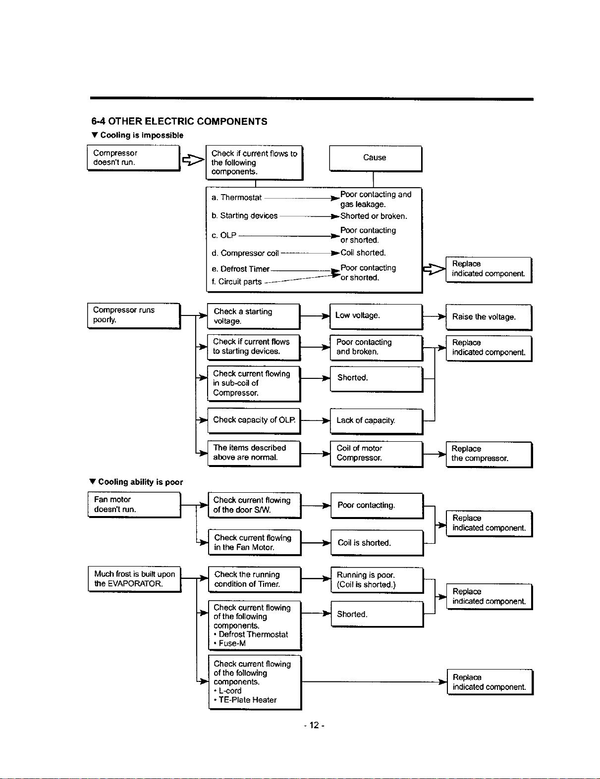
6_OTHER ELECTRIC COMPONENTS
• Cooling is impossible
doesn't run. I_
I Compressor I
I Compressor runs
poorly,
the following
Check if current flows to I [ Cause
components.
a. Thermostat _Poor contacting and
b. Starting devices m Shorted or broken.
c. OLP __ Poor contacting
d. Compressor coil
e. Defrost Timer _ Poor contacting
f. Circuit parts ______-_or shorted.
._ Check a starting _ Low voltage,
voltage.
to starting devices, and broken,
__ Check if current flows _ Poor contacting
in sub-coil of
._ Check current flowing _ Shorted.
Compressor.
, t
gasleakage.
or shorted.
Coilshorted.
I
Replace
indicated component. I
Raise the voltage. I
• Cooling ability is poor
Fan motor
doesn't run.
Muchfrost is builtupon L
the EVAPORATOR. /
-_ CheckcepecityofOLl_ _ Lack of capacity.
above are normal. Compressor.
._ The items described _ Coil of motor
__ heck current flowing
Poor contacting.
of the door S/W.
L_ Check current flowing
r I in the Fan Motor.
.._ Check the runningcondition of Timer.
Check current flowing
"_ of the following
components.
• Defrost Thermostat
• Fuse-M
Check current flowing
of the following
--_ components.
• L-cord
• TE-Plate Heater
_ Running is poor.
Coil is shorted.
(Coil is shorted.)
Shorted.
_ Replacethe compressor. I
indicated component.
Replace I
indicated component.
__.[ eplace I
> l Replace
indicated component. I
-12-
 Loading...