

LG LRTPC2031T, LRTPC1831T Owner’s Manual
SERVICING PRECAUTIONS
AIR RECHARGING IN COMPRESSOR
Test the re_geration system connecting it electrically before
refilling operation. It is necessary to ascertain the function
of the motor-compressor and identify the defects
immediately. If defects have been found, empty the old
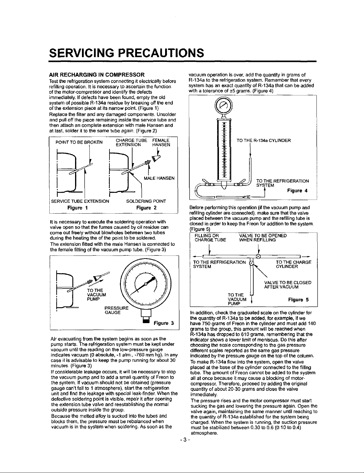
system of possible R-134a residue by breaking off the end
oftha extension piece at its narrow point. (Figure 1)
Replace the filter and any damaged components. Unsolder
and pull off the piece remaining inside the service tube and
then attach an complete extension with male Hansen and
at last, solder it to the same tube again. (Figure 2)
POINT TO BE BROKEN
SERVICE TUBE EXTENSION
Figure 1
It is necessary to execute the soldering operation with
valve open so that the fumes caused by oil residue can
come out freely without blowholes between two tubes
during the heating the of the point to be soldered.
The extension fitted with the male Hansen is connected to
the female fitting of the vacuum pump tube. (Figure 3)
CHARGETUBE FEMALE
EXTENSION HANSEN
MALE HANSEN
SOLDERING POINT
Figure 2
vacuum operation is over. add the quantity in grams of
R-134a to the refrigeration system. Remember that every
system has an exact quantity of R-134a that can be added
with a tolerance of +-5grams. (Figure 4)
TO THE R-134a CYLINDER
_ _ TOTHEREFRIGE_T_ON
SYSTEM
_-_ t Figure 4
Before performing this operation (if the vacuum pump and
refilling cylinder are connected), make sure that the valve
placed between the vacuum pump and the refilling tube is
closed in order to keep the Freon for addition to the system.
(Figure 5)
FILLING OR VALVE TO BE OPENED
CHARGE TUBE WHEN REFILLING
. VACUUM
Air evacuating from the system begins as soon as the
pump starts. The refrigeration system must be kept under
vacuum untti the reading on the low-pressure gauge
indicates vacuum (0 absolute, -1 stm., -760 mm hg). In any
case it is advisable to keep the pump running for about 30
minutes. (Figure 3)
If considerable leakage occurs, it will be necessary to stop
the vacuum pump and to add a small quantity of Freon to
the system, ff vacuum should not be obtained (pressure
gauge can't fall to 1 atmosphere), start the refrigeration
unit and find the leakage with special leak-finder. When the
defective soldering point is visible, repair it after opening
the extension tube valve and reestablishing the normal
outside pressure inside the group.
Because the melted alloy is sucked into the tubes and
bicoks them, the pressure must be rebalancod when
vacuum is in the system when soldering. As soon as the
THE
PRESSURE
GAUGE
TO THE REFRIGERATION TO THE CHARGE
SYSTEM CYLINDER
VALVE TO BE CLOSED
AFTER VACUUM
TO THE
VACUUM _ Figure 5
PUMP
In addition, check the graduated scale on the cylinder for
the quantity of R-134a to be added, for example, if we
have 750 grams of Freen in the cylinder and must add 140
grams to the group, this amount will be reached when
R-134a has dropped to 610 grams, remembering that the
indicator shows a lower limitof meniscus. Do this after
choosing the scale corresponding to the gas pressure
different scales reported as the same gas pressure
indicated by the pressure gauge on the top of the column.
To make R-t34a flow into the system, open the valve
placed at the base of the cylinder connected to the filling
tube. The amount of Freen cannot be added to the system
all at once because it may cause a blocking of motor-
compressor. Therefore, proceed by adding the original
quantity of about 20-30 grams and close the valve
immediately.
The pressure rises and the motor compressor must start
sucking the gas and Iowedng the pressure again. Open the
valve again, maintaining the same manner until reaching to
the quantity of R-134a established for the system being
charged. When the system is running, the suction pressure
must be stabilized between 0.30 to 0.6 (0.10 to 0.4)
atmosphere.
-3-
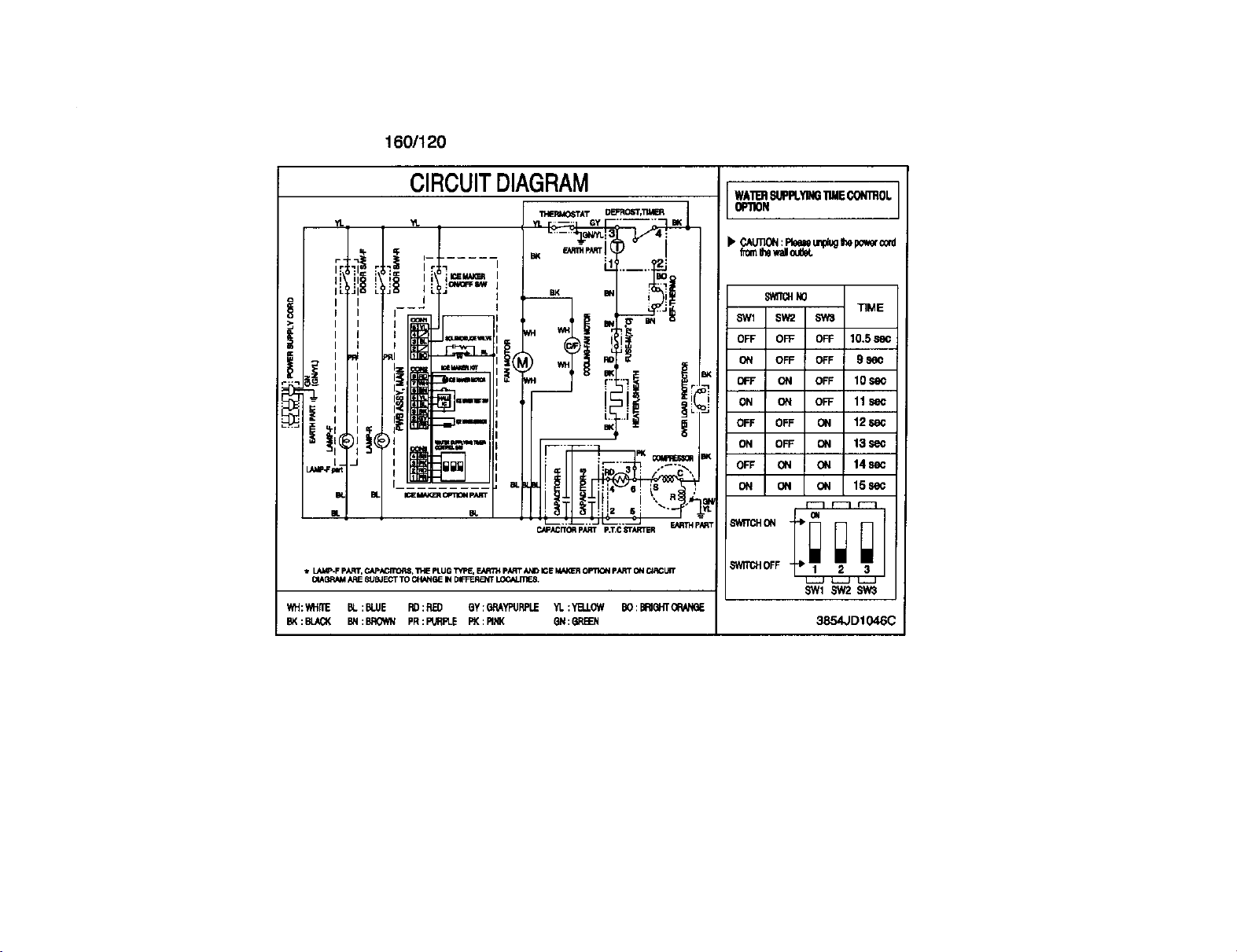
160/120
CIRCUITDIAGRAM
_ - .... GY .....
;A i : ; ! ]lliGi_IIiW "'!'.i
'_ I i I i
i_:_71!I-JI io iI __--- .il'.....
I I I iiil _ wi.i
I,
.i ,,,+,.,,,+,._...+._.:,,_a _-_Iil!
o!u. , , ++m_.--I
, - I I illi i
N" ' lmm,,.... - ! rl
....+_,_,,.,.,+1_"-I __+ i
I i il
_,c_,_,_,Im,l__--_"-""
i.. m. - _,_-=,_,_rT i '
i_ m. m
i LAI/P.F pARi', CAPACffl_II,8, "i'VE PLUG TVF_ E_ITH pART _ID ICE _ OPTII_ pART C¢i CIRCUIT
[_#IQilMil ARE 8'i.i_J ECT TO CIIANIIE IN D_ _,
WH:WHILE BL:BLUE RI) :RED 8Y : GRAYPURPLE YI. :'_LLOW lO :IRittT _
BK:BLA_ BN:BROtI?I PR:F_RPLE PI(:PINK 8N:GREEN
M. ! ,
i ! :RD 3 : /" C_',
[--.T_ __.2_JL_-- _- .. - F..idy_p.i,R T
_Acrn_ p_ p.T.C_r_qrrER
WATER81,'FPLYINGTIE CONI_OL
OImON
b' CAUTION:flue mpluglllll polar_i_
fcmlhlwalloulW.
Siall;tl No
SWI SW2 SWI
OFF OFF OFF 10,5
ON OFF OFF 9 86_
OFF ON OFF 10$ec
ON ON OR= 11SeC
OFF OFF ON 12 $_C
ON OFF ON 13 sec
OFF ON ON 14 sec
ON ON ON 15sec
r'-_ r--] _-1
_WlI_4 OFF t. 1 2 3
L-iJ _ Li-J
SW1 _ SW3
TIME
oN
3854JD1046C
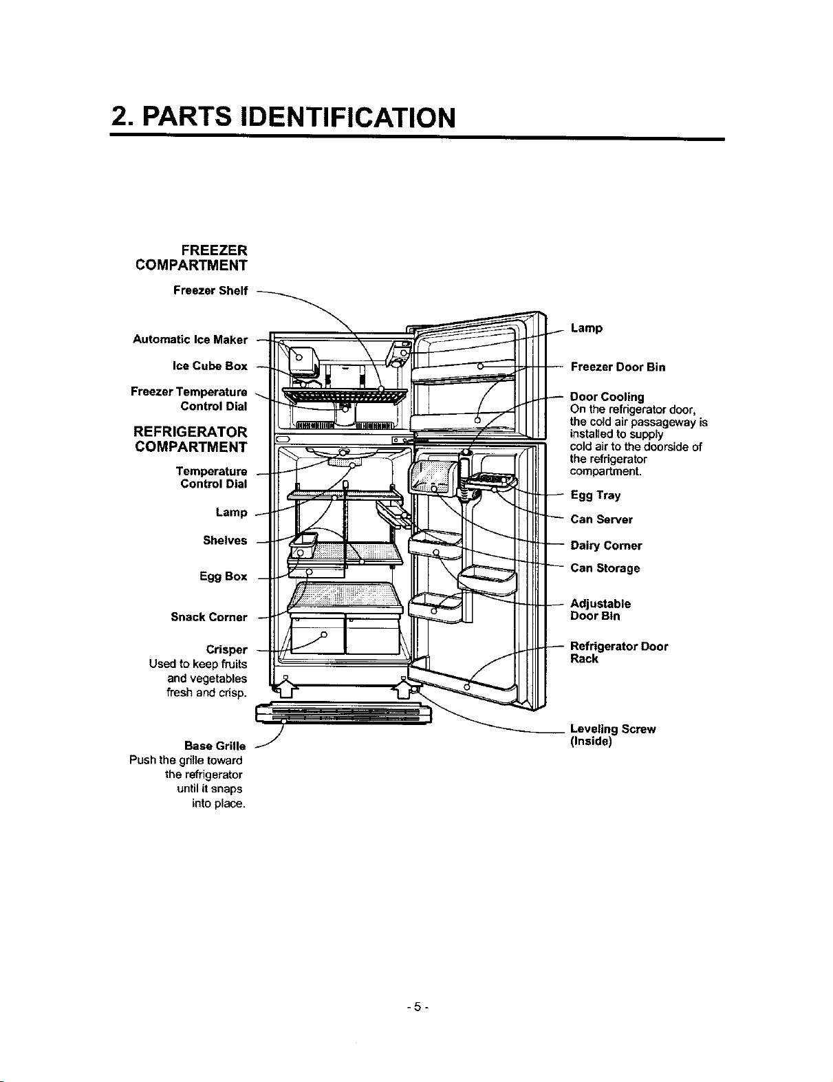
2. PARTS IDENTIFICATION
FREEZER
COMPARTMENT
Freezer Shelf
Automatic Ice Maker
Ice Cube Box
Freezer Temperature
Control Dial
REFRIGERATOR
COMPARTMENT
Temperature
Control Dial
Lamp
Shelves
Egg Box
Snack Comer
Crisper
Used to keep fruits
and vegetables
fresh and crisp.
Lamp
Freezer Door Bin
Door Cooling
On the refrigeratordoor,
the cold air passageway is
installedto supply
coldairto the doorsideof
the refrigerator
compartment.
Egg Tray
Can Server
Dairy Comer
Can Storage
ustable
Door Bin
Refrigerator Door
Rack
Base Grille
Pushthe grilletoward
the refrigerator
untilit snaps
intoplace.
Leveling Screw
(Inside)
-5-
3. DISASSEMBLY
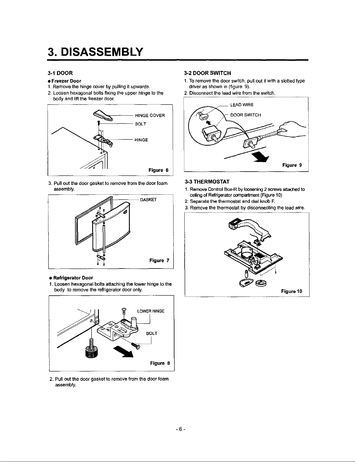
3-1 DOOR
• Freezer Door
1. Remove the hinge cover by pulling it upwards.
2. Loosen hexagonal bolts fixing the upper hinge to the
body and lift the freezer door.
BOLT
_. HINGE COVER
3. PuN out the door gasket to remove from the door foam
assembly.
HINGE
Figure 6
GASKET
3-2 DOOR SWITCH
1. To remove the door switch, pull out itwith a slotted type
driver as shown in (figure g).
2. Disconnect the lead wire from the switch.
LEAD WIRE
DOOR SWITCH
Figure 9
3-3 THERMOSTAT
1. Remove Contral Box-R by loosening 2 scre,,_ attached to
ceiling of Refrigerator compadrnent (F_gure10)
2. Separate the thermostat and dial knob E
Remove the thermostat by disconnecting the lead wire.
Figure 7
• Refrigerator Door
1. Loosen hexagonal bolts attaching the lower hinge to the
body to remove the refrigerator door only.
LOWER HINGE
BOLT
__J
Figure 8
2. Pull out the door gasket to remove from the door foam
assembly.
Figure 10
-6-
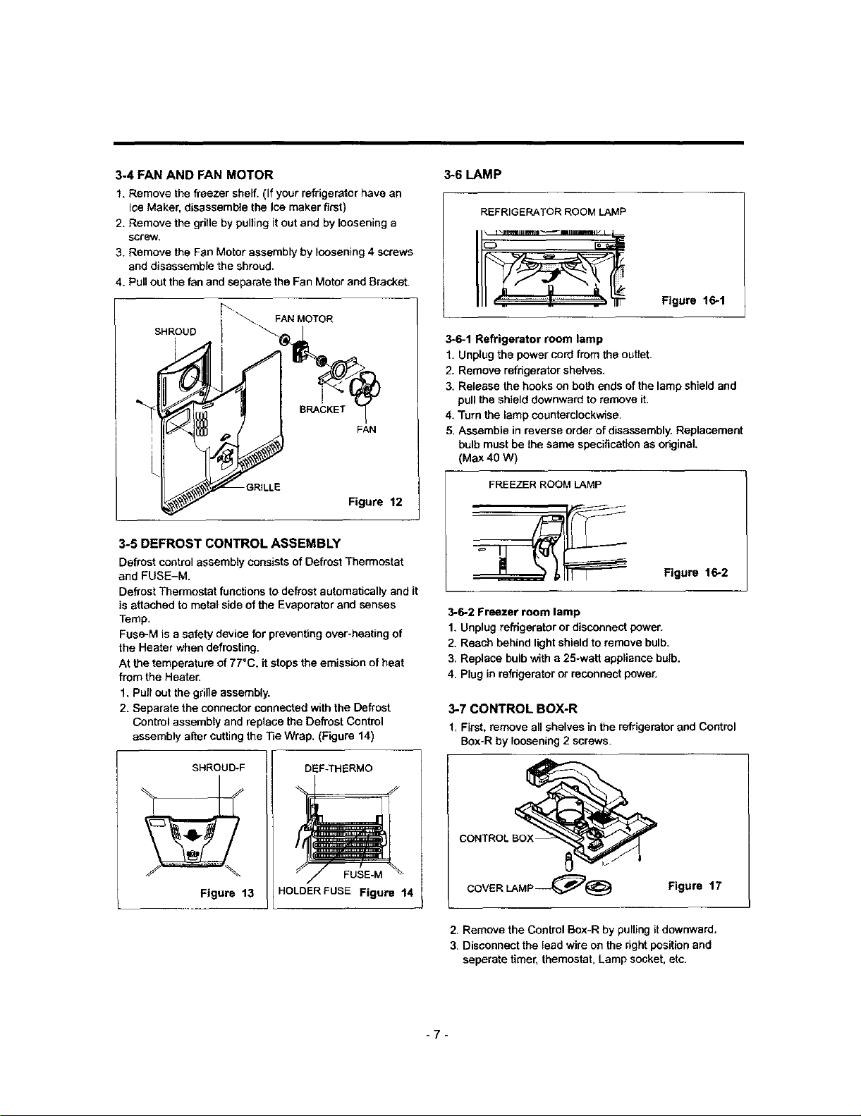
3-4 FAN AND FAN MOTOR
1. Remove the freezer shelf. (If your refrigerator have an
Ice Maker, disassemble the Ice maker first)
2. Remove the grille by pulling it out and by loosening a
screw.
3. Remove the Fan Motor assembly by loosening 4 screws
and disassemble the shroud.
4. Pull out the fan and separate the Fan Motor end Bracket.
SHROUD
_\._FAN MOTOR
FAN
Figure 12
3-5 DEFROST CONTROL ASSEMBLY
Defrost control assembly consists of Defrost Thermostat
and FUSE-M.
Defrost Thermostat functions to defrost automatically and it
is attached to metal side of the Evaporator and senses
Temp,
Fuse-M is a safety device for preventing over-heating of
the Heater when defrosting.
At the temperature of 77°C, it stops the emission of heat
from the Heater.
1. Pull out the grille assembly.
2. Separate the connector connected with the Defrost
Control assembly and replace the Defrost Control
assembly after cutting the Tie Wrap. (Figure 14)
3-6 LAMP
REFRIGERATOR ROOM LAMP
Figure 16-1
3-6-1 Refrigerator room lamp
1. Unplug the power cord from the outlet.
2. Remove refrigerator shelves.
3. Release the hooks on both ends of the lamp shield and
pull the shield downward to remove it.
4, Turn the lamp counterclockwise.
5. Assemble in reverse order of disassembly. Replacement
bulb must be the same specification as ofiginak
(Max 40 W)
FREEZER ROOM LAMP
Figure 16-2
3-6-2 Freezer room lamp
1. Unplug refrigerator or disconnect power.
2. Reach behind light shield to remove bulb.
3. Replace bulb with a 25-watt appliance bulb.
4. Plug in refrigerator or reconnect power.
3-7 CONTROL BOX-R
1, First, remove all shelves in the refrigerator and Control
Box-R by loosening 2 screws.
SHROUD-F
L__. ,_ Figure 13
DEF_HERMO
FUSE-M
HOLDERFUSE Figure 14
I
COVER LAMP_@ Figure 17
2. Remove the Control Box-R by pulling itdownward.
3. Disconnect the lead wire on the right position and
seperate timer, themostat, Lamp socket, etc.
-7-
4. ADJUSTMENT
4-1 COMPRESSOR
4-1-1 Role
The compressor intakes low temperature and low pressure
gas evaporated from evaporator of the refrigerator, and
condenses this gas to high temperature and high pressure
gas, and then plays delivering role to condenser.
4-1-2 Composition
The compressor includes ovedoad protection. The PTC
starter and OLP (overload protector) are outside the
compressor. Since the compressor is manufactured to
tolerances of I micron, and is sealed in a dust - and
moisture - free environment, use extreme caution when
repairing it.
4-1-3 Note for Usage
(1) Be careful not to allow over-voltage and over*current.
(2) No Stdke
If applying forcible power or strike (dropping or careless
handling), poor operation and noise may occur.
(3) Use proper electnc components appropriate to the
Compressor.
(4) Note to Keep Compressor.
If Compressor gets wet in the rain and rust in the pin of
Hermetic Terminal, the result may be poor operetlen
and poor contact may cause.
(5) Be careful that dust, humidity, and welding flux don't
contaminate the compressor inside when replacing the
Compresson Dust, humidity, and flux due to welding
which contaminates the cylinder may cause Iocknge
and noise.
4-2 PTC-STARTER
4-2-1 Composition of PTC-Starter
(1) PTC (Positive Temperature Coefficient) is a no-contaet
semiconductor starting device which uses ceramic
material consisting of BaTiOs.
(2) The higher the temperature is, the higher the resistance
value. These features am used as starting device for
the Motor.
4-2-2 Role of PTC-Starter
(1) PTC is attached to Hermetic Compressor used for
Refdgeretor, Show Case, and starting Motor.
(2) Compressor for household refrigerator applies to
single-phase induction Motor.
For normal operation of the single-pbase induction
motor, in the starting operation flows in both main coil
and sub-coiL After the starting isover, the current in
subcoil is cut off. The proper features of PTC play all
the above roles. So, PTC is used as a motor starting
device.
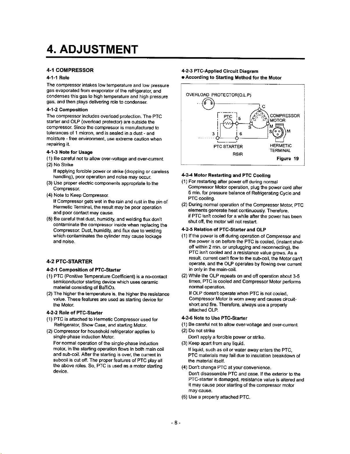
4-2-3 PTC-Appltad Circuit Diagram
• According to Starting Method for the Motor
OVERLOAD PROTECTOR(O.L.P)
o
F -75 cog ESSOR
PTC STARTER HERMETIC
RSIR
4-24 Motor Restarting and PTC Cooling
(1) For restarting after power off dudng normal
Compressor Motor operation, plug the power cord after
5 min. for pressure balance of Refdgerafing Cycle and
PTC cooling.
(2) During normal operation of the Compressor Motor, PTC
elements generate heat cot_inuously. Therefore,
if PTC isn't cooled for a while after the power has been
shut off, the motor will not restart.
4-2-5 Relation of PTC-Starter and OLP
(I) If the power is off dudng operation of Compressor and
the power is on before the PTC is cooled, (instant shut-
off within 2 min. or unplugging and reconnecting), the
PTC isn't cooled and a resistance value grows. As a
result, current can't flow to the sub-coil, the Motor can_
operate, and the OLP operates by flowing over current
in only in the main-coil.
(2) While the OLP repea_ on and off operation about 3-5
times, PTC is cooled and Compressor Motor performs
normal operation.
If OLP doesn't operate when PTC is not cooled,
Compressor Motor is worn away and causes circuit-
short and fire. Therefore, always use a properly
attached OLP.
4-2-6 Note to Use PTC-Starter
(1) Be careful not to allow over-voltage and over*current.
(2) Do not stdke
Don't apply a forcible power or strike.
(3) Keep apart from any liquid.
If liquid, such as oil or water away enters the PTC,
PTC materials may fail due to insulation breakdown of
the material itself.
(4) Don't change PTC at your convenience.
Don'[ disassemble PTC and case. If the exterior to the
PTC-starter is damaged, resistance value is altered and
it may cause poor starting of the compressor motor
may cause.
(5) Use a properly attached PTC.
TERMINAL
Figure 19
-8-
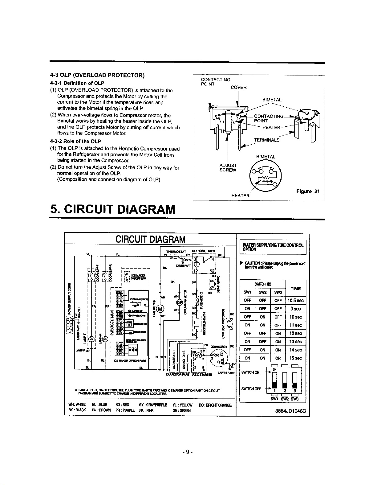
4-30LP (OVERLOAD PROTECTOR)
4-3-1 Definition of OLP
(1) OLP (OVERLOAD PROTECTOR) is attached to the
Compressor and protects the Motor by cuttingthe
current to the Motor if the temperature rises and
activates the bimetal spring in the DLP.
(2) When over-voltage flows to Compressor motor, the
Bimetal works by hea_ing the heater inside the OLP,
and the OLP protects Motor by cutting off current which
flows to the Compressor Motor.
4-3-2 Role of the OLP
(1) The DLP is attached to the Hermetic Compressor used
for the Refrigerator and prevents the Motor Coil from
being started in the Compressor.
(2) Do not turn the Adjust Screw of the OLP in any way for
normal operation of the OLP.
(Composition and connection diagram of OLP)
5. CIRCUIT DIAGRAM
CONTACTING
POINT
COVER
_ _ BIMETAL
SCREW
ADJUST
HEATER
BIMETAL
Figure 21
CIRCUITDIAGRAM
ICSJ
_S_W
q
ww_l
mm
==ram I
II='_==1
a_w I
ILi
IC_ I#A_=i OPT_ pater
EL
t L,M#P-Fp._RT,CAPAI_TOR_"hE pLt_l "i_ EAR'RtpN_r M_DICEM,il_ Opi3Ofl pARTONCIRCUtT
DIAGRA_ARESUB,IECT10 Ck_tGE IN _ LOCNJI1E_
WH: WHITE BL :BLUE RD ; RED 6Y :GRAYPURPLIE YL :YB.LOW BO: BflJGHTORikNGE
BK:BLAO( BN:BROWN PR:PJRPLE PK:PINK GN:GREE_J
II 5
C._i,ILCffO_ pART p_i'.C 83"N_E R F-A_I_I PAR[
•
il
WATI_ISBPPLYI__ _If_ROL
OPTION
• C_UIION:Phaseumlugth*l:_Wo_
lTor_Ih8walloulel.
5'_T(_ND
SW1 SW2 SW3
OFF OFF OFF 10.5=
ON OFF OFF 9 sec
OFF ON OFF 10S_
ON ON OFF 11se
OFF OFF ON 12S_
ON OFF ON 13S_
OFF ON ON 14s_
ON ON ON 15S_
SWITCHOFF 2 3
L_.J _ _
SWl sw2 sw3
TIME
3854JD1046C
-9-
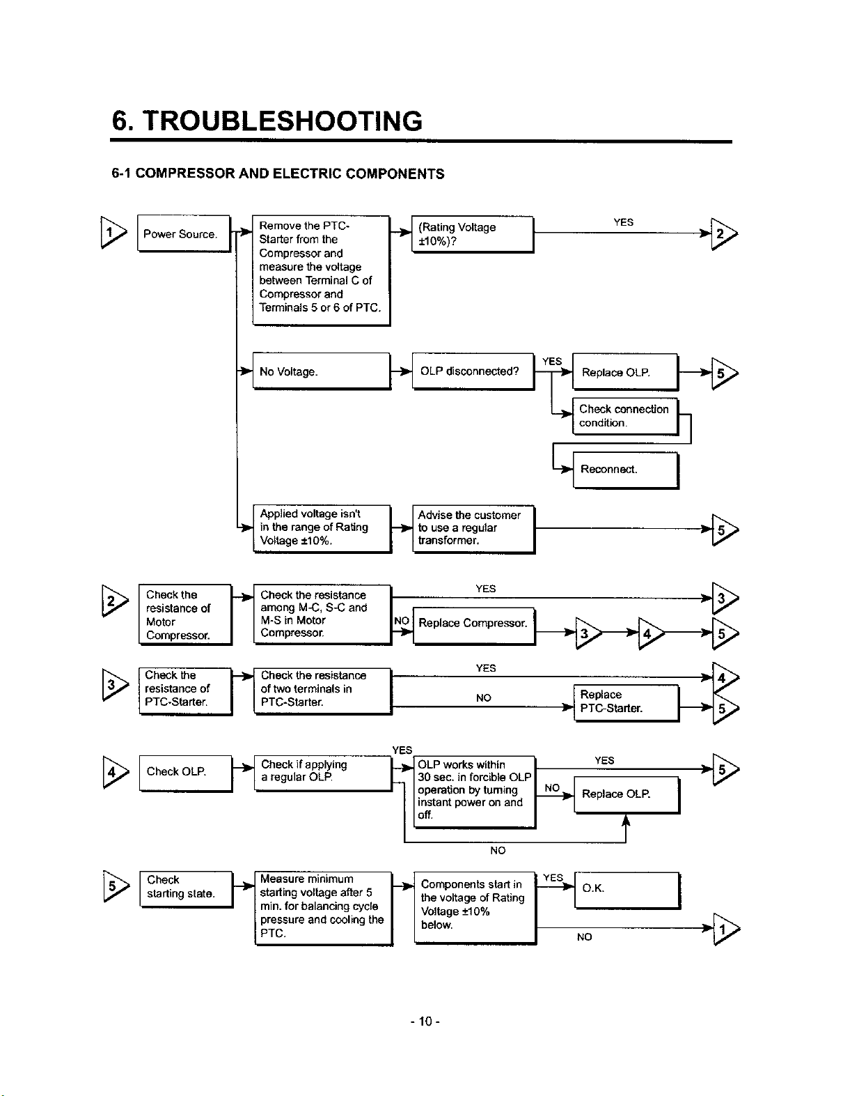
6. TROUBLESHOOTING
6-1 COMPRESSOR AND ELECTRIC COMPONENTS
Remove the PTC-
[_ I Power Source.
Starter from the
Compressor and
measure the voltage
between Terminal C of
Compressor and
Terminals 5 or 6 of PTC.
No Voltage. _]_ OLP disconnected?
__ (Rating Voltage YES
±10%)? I "[_
Replace OLP.
condition.
Check conneclton __]
Reconn I
_,. in the range of Rating ,I to use a regular
VO rage ±10%. i transformer.
Check the _ Check the resistance
Motor M-S in Motor
resistance of i ° I among M-C, S-C and
Compressor. Compressor.
Check the _- Check the resistance
PTC-Starter. PTC-Starter.
resistance of i I of two terminals in
[_ _ Check if applying
[_ Check
Check OLP. a regular OL_
starting state.
_ F
starting voltage after 5 i I the voltage of Rating " "
min. for balancing cycle i I Voltage -+10%
_ Measure minimum _-_ Components start in _-_ O K
PTc.pressureand cooling the I Lbelow. J NO
I
N_O YES _- [3[3[3_
Replace Compressor.
Replace
NO _- PTC-Starter.
YES
30 sec. in forcible OLP
operation by turning Replace OLP.
instant power on and
_ LP w°rks within _ YES i _'[_
Off. f
NO
I
I
-10-
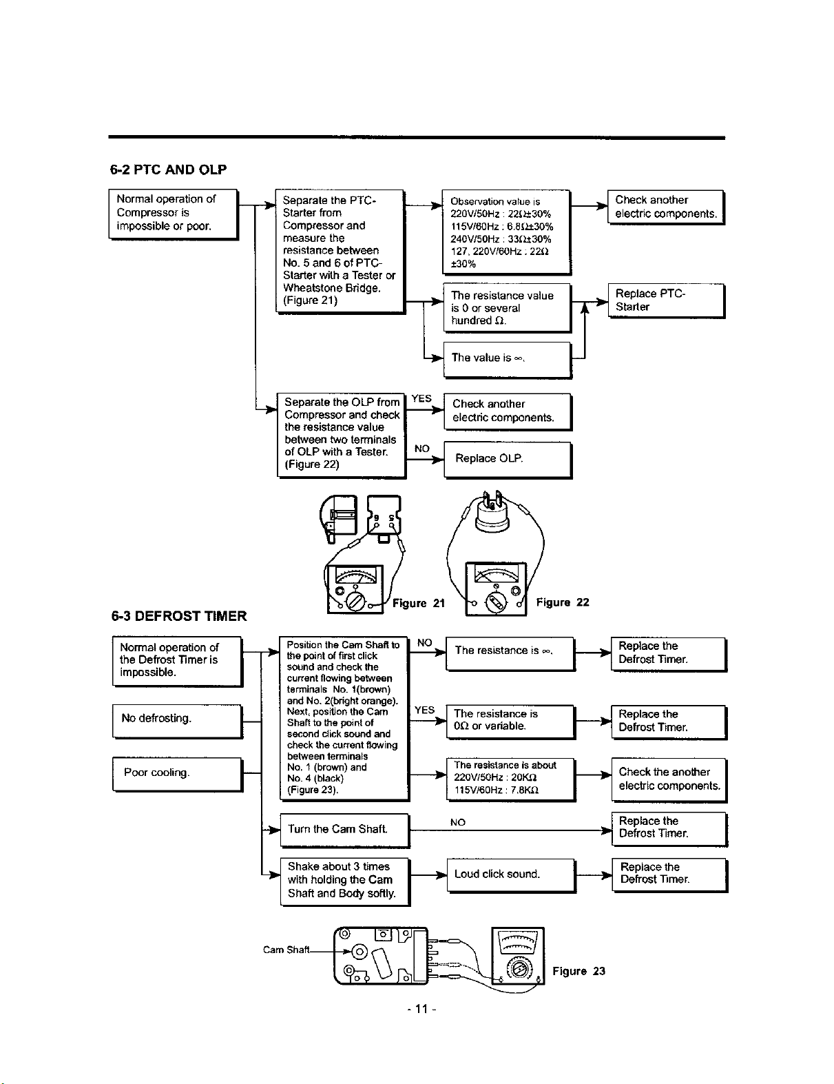
6-2 PTC AND OLP
Normal operation of t'_
Compressor is --_
impossible or poor.
/
Separate the PTC-
Starter from
Compressor and
measure the
resistance between
No. 5 and 6 of PTC-
Starter with a Tester or
Wheatstone Bridge.
(Figure 21)
Compressor and check I Vl eLectdc components. I
the resistance value I I
between two terminals I
Separate the OLP from] YES_ Check another
of OLP with a Tester. _ I
(Figure 22) _ Replace OLP.
Observation value is
220V/50Hz : 22_30%
115V/60Hz : 6 8_,E1:30%
240V/50Hz :33.(Z_30%
127,220VI60Hz : 22_)
-+30%
The resistance value
is 0 or several
hundred _.
The value is _.
Check another Ielectric components.
Replace PTC-
Starter
I
I
6-3 DEFROST TIMER
the Defrost Timer is
Normal operation of
impossible.
No defrosting.
Poor cooling.
--]P the point of first click
sound and check the
current flowing between
terminals No. 1(brown)
and No, 2(bright orange).
Position the Cam Shaft to
Next, position the Cam
Shaft to the point of
second click sound and
check the current flowing
between terminals
No. 4 (black)
.__ NO. 1(brown) and
(Figure 23).
-}_ Turn the Cam Shaft.
-}P with holding the Cam
I Shake about 3 times
Shaft and Body softly.
..-_ The resistance is ,_.
0Q or variable.
.Y_ The resistance is
220VISOHz: 20K_
__Tbe resistanceisabout
115V/60Hz: 7.8K_
I N°
I_ Loud clicksound.
-11 -
I ;eefp °acstethmeer.I
I_t Checkthe another I
Figure 23
electric components. I
7-- Replace the
Defrost Timer. I
I
 Loading...