

LG GR-382R, LRTP1231xx, LRTP1231W Service Manual

SERVICE MANUAL
REFRIGERATOR
ATTENTION
Before start servicing, carefully read the safety instructions
in this manual
MODEL(S): GR-382R
LRTP1231W
Contents
Safety Precautions ----------------------------------------------- -------------------------------------- 1
Service Precautions ----------------------------------------------------------------------------------- 2-3
Specifications ------------------------------------------------------------------------------------------- 4
Feature Chart ------------------------------------------------------------------------------------------- 5
Circuit Diagram ------------------------------------------------------------------------------------------ 6-7
Cooling Systems ---------------------------------------------------------------------------------------- 8
Product Disassembly ---------------------------------------------------------------------------------- 9-11
Doors ------------------------------------------------------------- ----------------------------------------- 9
Door Switch ---------------------------------------------------------------------------------------------- 9
Electronic Control Display PCB ----------------------------------------------------------------- --- 9
Freezer Fan ---------------------------------------------------------------------------------------------- 10
Defrost Control ------------------------------------------------------------------------------------------ 10
Lamp ------------------------------------------------------------------------------------------------------- 10
Refrigerator Control Box ------------------------------------------------------------------------------ 11
Reversible Door --------------------------------------- --------------------------------------------------- 12-13
Adjustments ----------------------------------------------------------------------------------------------- 14-15
Compressor ---------------------------------------------------------------------- ------------------------ 14
PTC Starter----------------------------------------------------------------------------------------------- 14
Overload Protector (OLP) ---------------------------------------------------------------------------- 15
Troubleshooting ----------------------------------------------------------------------------------------- 16-21
Compressor & Electrical Components ------------------------------------------------------------ 16
PTC & OLP ------------------------------------ ---------------------------------------------------------- 17
Other Electrical Components ----------------------------------------------------------------------- 18
Service Diagnosis Chart ------------------------------------------------------------- ----------------- 19
Refrigerant Cycle --------------------------------------------------------------------------------------- 20-21
MICOM circuit & operation --------------------------------------------------------------------------- 22-39
Refrigerator Exploded View-------------------------------------------------------------------------- 40-41
Service Parts list----------------------------------------------------------------------------------------- 42-43
Safety Precautions.
Read the following inst ructions before servicing your refrigerator.
1. Unplug the refrigerator before
servicing.
2. Visually inspect for gas leakage or
short circuit.
3. If testing with the refrigerator
plugged in, wear rubber gloves to
avoid electric shock.
4. Do not touch frozen metal parts;
your hands could freeze to the
surface. This
5. Be sure that no water is dripping
may cause frostbite.
towards electrical or metal parts.
6. If you check the bottom part of the
refrigerator while the freezer
door is open, be careful standing
up. You
could bump your head.
7. When you tilt your refrigerator be
sure to take out all metal, glass, or
other loose
parts.
8. When servicing the evaporator,
wear cotton gloves to prevent cutting
by any of
the evaporator fins.
1

Service Precautions
Refrigerant Recharging
Test the compressor's operation before
recharging the refrigerant; this is very
important to detect failures and to
ensure the proper motor running, and
to identify failures immediately. If
failure has been detected, clean the
system from any other possible
R-134a residues by breaking the final
part of the compressor's service pipe
at it's thinnest part as shown in Fig. #1.
Replace the filter and any other part
that could be deteriorated. Unweld
and pull out the service pipe,
then place a new pipe extension with a
Hansen male connector and solder
the new pipe. See Fig. #2
0(absolute or -1 atm, -760 mm Hg.) It
is not recommend to run the vacuum
pump for more than 30 minutes. See
Figure 3.
In case there is a large leak and the
vacuum operation must stop,
you must add a small amount of
refrigerant to the system and check
with an electronic leak detector. If a
soldering failure is detected, open the
valve before soldering to equalize the
pressure and keep solder from being
blown out of the joint or sucked into
the piping.
It is necessary to open the valve
when soldering to allow the gases to
escape without forcing the molten
solder out of the joint. The extension
with the male Hansen connector
should be connected to a female type
connector to the vacuum pump's pipe.
See Fig. #3
System air evacuation starts as soon
as the pump begins to run. The
system must be kept under vacuum
until the low pressure gauge shows
As soon as the repair is completed,
charge the correct amount of
refrigerant into the system.
Remember that each system requires
a specific amount of refrigerant with a
tolerance of ±5 grams. See Figure 4.
Before performing this operation (if
the vacuum pump and charging
cylinder are still attached to the
system) be sure the valve between
the pump and the cylinder is closed to
2
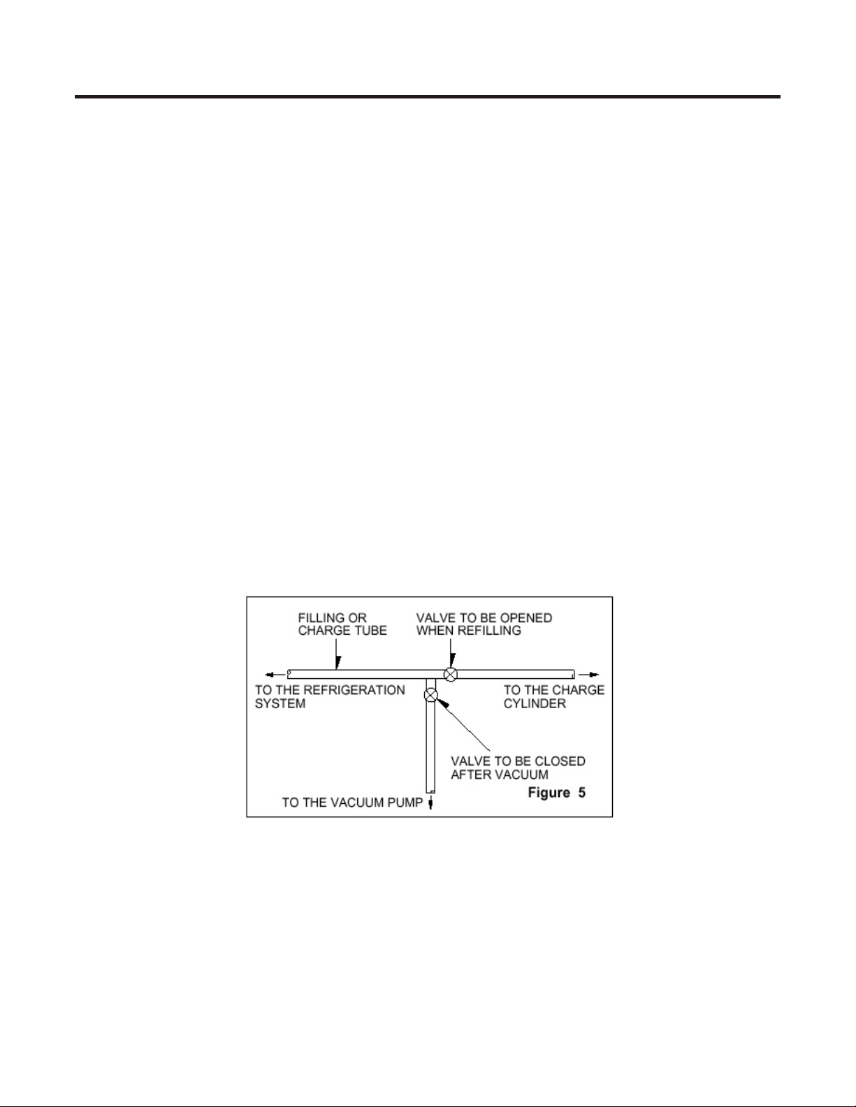
Service Precautions
keep refrigerant out of the system.
See Figure 5.
For gas charging, check the
graduated scale on the cylinder to see
the amount of refrigerant that it
contains and the amount that will be
pumped into the system. For
example, if you have 750 grams of
refrigerant in the cylinder and we
have to pump 165 grams to the
system, this amount will be reached
when the indicator reaches 585
grams; remember that the indicator
shows a lower level of meniscus.
Do this after choosing the scale
corresponding to the gas pressure
indicated on the pressure indicator
located on the upper part of the
column. To let R-134a flow into the
system, open the valve at the
recharging cylinder's base. The total
amount of refrigerant should not be
installed in one session, as it could
block the compressor. Install 20~30
grams at a time and close the valve.
The compressor will run and the
pressure will drop. Then open the
valve and install other 20~30 grams
of refrigerant. Repeat this procedure
until the entire amount has been
added to the system. Under operating
conditions, the system pressure
should stabilize between 0.3 and 0.6
atm.
3


Feature Chart
FREEZER
Temperature
Control
Shelf
Ice Trays
Twist´n Serve
REFRIGERATOR
Temperature
Control
Fresh Meat
Tray
Lamp
Shelves
(Plastic or Glass)
Deodorizer
(Absorbs
Odors)*
Multi Air Flow
Air flow distributor
Freezer
Door Baskets
Refrigerator
Door Baskets
Vegetable Tray
(Keeps fruits and
vegetables fresh)
MODEL(S): GR-382R
LRTP1231W
* This part is only included in model LRTP1231W
Magic Crisper
(Vegetable Tray cover
that control humidity)
5
Leveling
Screws


Graphic Circuit Diagram
Brown
Red
Pink
Yellow
Blue
Violeta
Whitte
White
White
White
Brown
Red
Red
Blue
Orange
Orange
Yellow
Blue
c
C
C
Brown
Red
Orange
Orange
Blue
Black
Switch
Violet
Yellow
Thermal Fuse
Defrost Resistance
Evaporator
Defrost Resistance
Fan
(Heater Cord)
Sensor
Lamp
Control
Sensor
Brown
Blue
Red
Blue
Sensor
CON2
Defrost and Temperature Electronic Control
CON1
Black
Yellow
Blue
Black
Fan
Motor
Blue
AC Current
Brown
Pink
Blue
Pink
Black
OLP
M
Running Capacitor
COMPRESSOR
7
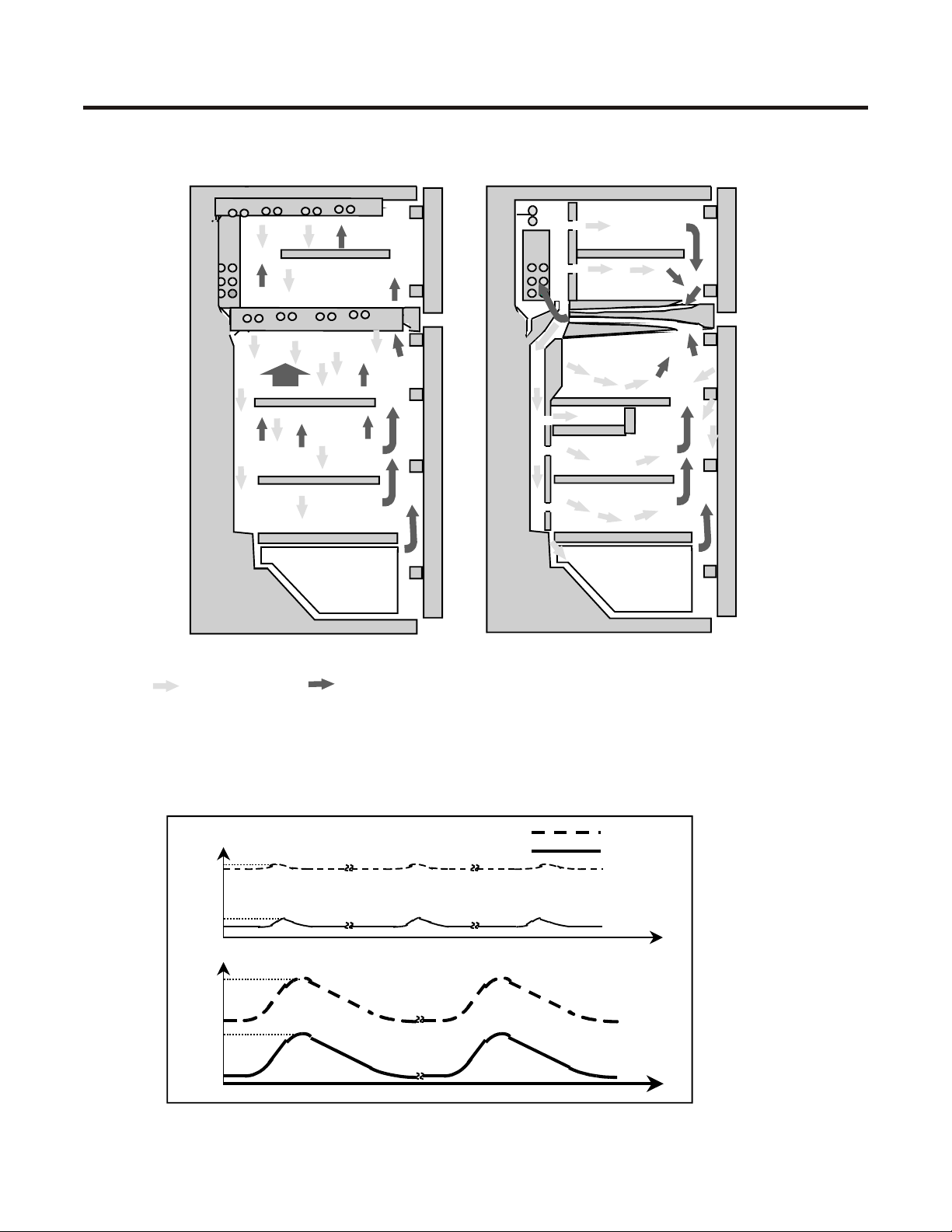
Cooling Systems
Direct System Indirect System
Important: Check that the air ducts are not
Cold Air
Temperature variation during defrosting time, depending upon the cooling system .
Temp.( ? )
4
3
-16
-18
Temp.( ? )
18
Warm Air
obstructed for a better cooling
performance.
Indirect System
Direct System
Refrigerator
Freezer
Tim
e
3
-3
-18
Tim
e
8

3. Product Disassemble.
Doors
Freezer Door
1. Remove hinge cover by pulling it
upwards.
2. Loosen the hexagonal bolts that
hold the upper hinge in place. See
Figure 1.
3. Remove door. See Figure 2.
Figure 1
Figure 2
4. Pull gasket to remove it. See
Figures 3 and 4.
2. Disconnect all switche's cables.
See Figure 8
Figure 7
Figure 8
Control Circuit ( Display PWB)
1. Remove the lamp cover by
inserting a screwdriver in the lower
side's holes. See Figure 9.
2. Loosen and remove the 2 screws.
See Figure 10.
Figure 3
Figure 4
Refrigerator Door.
1. Loosen the hexagonal bolts that
hold the central hinge in place.
See Figure 5.
2. Remove refrigerator door. See
Figure 6.
3. Pull out the gasket to remove it
from the door. See Figure 4 from
Freezer door.
Figure 5
Figure 6
Door Switch
1. Pull out the door switch out using
a flat head screwdriver. See
Figure 7
Figure 9 Figure 10
3. Pull out the Control Box. See
Figure 11.
4. Disconnect the connector from the
cable terminal. See Figure 12.
5. Remove the EPS Multi air duct
(insulation) from the control box.
6. Detach the electronic control
(Display, PWB). See Figure 13.
Figure 11
Figure 12
9

Figure 13
Fan and Fan Motor.
1. Remove freezer shelf.
3. Remove the ice bin assembly by
pulling it to the right side, until it
snaps out.
4. Remove Grill Fan screw cover.
See Figure 14.
5. Loosen the screw. See Figure 15.
6. Pull out the fan cover. Figure 16.
Defrost Control Assembly
1. The defrost control assembly
consists of one thermistor and a
fuse that melts with heat.
2. The termistor's function is to
sense the compartment's
temperature and automatically
stop the defrost. The termistor is
located beside of the evaporator
bracket.
3. The melting fuse is a safety device
to prevent an overheating of the
defrosting resistance when it
operates.
4. The fuse melts at 162° F and the
resistance heater stops.
5. To replace this components,
please follow the steps mentioned
at Figure 18.
Figure 14
Figure 15
6. Unplug the connector.
7. Remove the fan holder shroud.
Figure 17.
8. Remove fan and loosen both
screws that hold the bracket.
9. Remove the motor bracket and the
rubber parts. Pull out the fan
motor. See Figure 17.
Figure 16
Figure 17
1. Figure 18. Unplug the connector plugged to
Lamp.
Refrigerator Compartment Lamp
1. Remove the lamp cover with
a screwdriver or a similar tool.
See Figure 19.
2. Remove the lamp by unscrewing it
counterclockwise and replace it
with the same specifications
(125V,20W). Part Number
6912JB2002J.
10
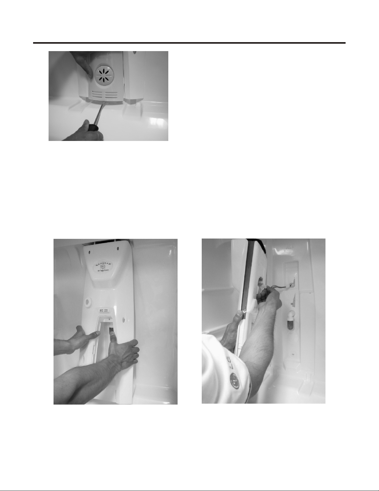
Figure 13
Figure 19
Refrigerator Control Box.
Remove the lamp cover as mentioned
before.
1. Loosen the screws.
2. Remove the entire control box.
See Figure 20.
3. Disconnect the control box
connector. See Figure 21.
Figure 20 Figure 21
11

4. Reversible Door
PRECAUTION
1. Before reversing the doors, remove all foods and accesories,
like shelves or trays, which are not attached to the doors.
2. Use a Philips screwdriver, bolt driver, torque wrench, or spanner to
tighten and loosen the bolt.
3. Be careful not to drop the refrigerator or door when assembling or
disassembling lower hinge or the Adjustable Screw Assembly.
4. Don´t lay the refrigerator down to work on it. It will cause
malfunction.
5. The doors may be reversed to provide left or right opening, depending upon the customer´s
preference.
HOW TO REPLACE THE DOOR OPENING LEFT TO RIGHT
(when converting from left-opening to right opening)
12

13 14
 Loading...