

LG LRTGC1815W, LRTGC1815BS Owner’s Manual
SERVICING PRECAUTIONS
AIR RECHARGING IN COMPRESSOR
Test the refrigeration system connecting it electrically before
refilling operation. It is necessary to ascertain the function
of the motor-cempressor and identify the defects
immediataly. If defects have been found, empty the old
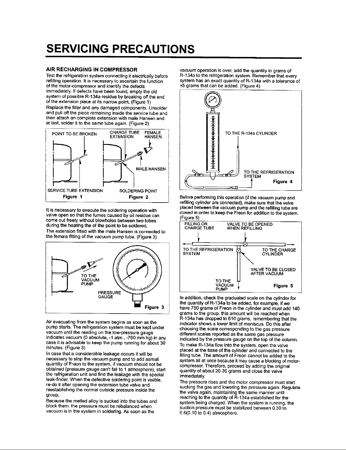
system of possible R-134a residue by breaking off the end
of the extension piece at its narrow point. (Figure 1)
Replace the filter and any damaged components. Unsolder
and pull off the piece remaining inside the service tube and
then attach an complete extension with male Hansan and
at last, solder it to the same tube again. (Figure 2)
POINT TO BE BROKEN
SERVICE TUBE EXTENSION
Figure 1
It is necessary to execute the soldering operation with
valve open so that the fumes caused by oil residue can
come out freely without blowholes between two tubes
dudng the beating the of the point to be soldered.
The extension fitted with the male Hansen is connected to
the female fitting of the vacuum pump tube. (Figure 3)
CHARGETUBE FEMALE
EXTENSION HANSEN
MALE HANSEN
SOLDERING POINT
Figure 2
vacuum operation is over, add the quantity in grams of
R-134a to the refrigeration system. Remember that every
system has an exact quanti_y of R-134a with a tolerance of
-+5grams that can be added. (Figure 4)
TO THE R-134a CYLINDER
1
STEM Figure 4
Before performing thisoperation (if the vacuum pump and
refilling cylinder are connected), make sure that the valva
placed between the vacuum pump and the refilling tube are
closed in order to keep the Freon for addition to the system.
(Figure 5)
FILLING OR VALVE TO BE OPENED
CHARGE TUBE WHEN REFILLING
_r
TOTHE REFRIGERATION TO THE CHARGE
SYSTEM CYLINDER
Air evacuating from the system begins as soon as the
pump starts. The refrigeration system must be kept under
vacuum until the reading on the low-pressure gauge
indicates vacuum (0 absolute, -1 atm., -760 mm hg) in any
case it is advisable to keep the pump running for about 30
minutes. (Figure 3)
In case that a considerable leakage occurs it will be
necessary to stop the vacuum pump and to add asmati
quantity of Freon to the system, if vacuum should not be
obtained (pressure gauge can't fall to 1 atmosphere), start
the refrigeration unit and find the leakage with the special
leak-finder. When the defective soldering point is visible,
re-do it after opening the extension tube valve and
reestablishing the normal outside pressure inside the
group.
Because the melted alley is sucked into the tubes and
block them. the pressure must be rehelanced when
vacuum is in the system in soldedng. As soon as the
VALVE TO BE CLOSED
AFTER VACUUM
TO THE
VACUUM
PUMP
In addition, check the graduated scale on the cylinder for
the quantity of R-134a to be added, for example, if we
have 750 grams of Freon in the cylinder and must add 140
grams to the group, this amount will be reached when
R-134a has dropped to 610 grams, remembering that the
indicator shows a lower limit of meniscus. Do this after
choosing the scale corresponding to the gas pressure
different scales reported as the same gas pressure
indicated by the pressure gauge on the top of the column.
To make R-134a flow into the system, open the valve
placed at the base of the cylinder and connected to the
filling tube. The amount of Freon cannot be added to the
system all at once because it may cause a blocking of motor-
compressor. Therefore, proceed by adding the original
quantity of about 20-30 grams and close the valve
immediately.
The pressure nsas and the motor compressor must start
sucking the gas and lowering the pressure again. Regulate
the valve again, maintaining the same manner until
reaching to the quantity of R-134a established for the
system being charged. When the system is running, the
suction pressure must be stabilized between 0.30 to
0.6(0.10 to 0.4) atmosphere.
Figure 5
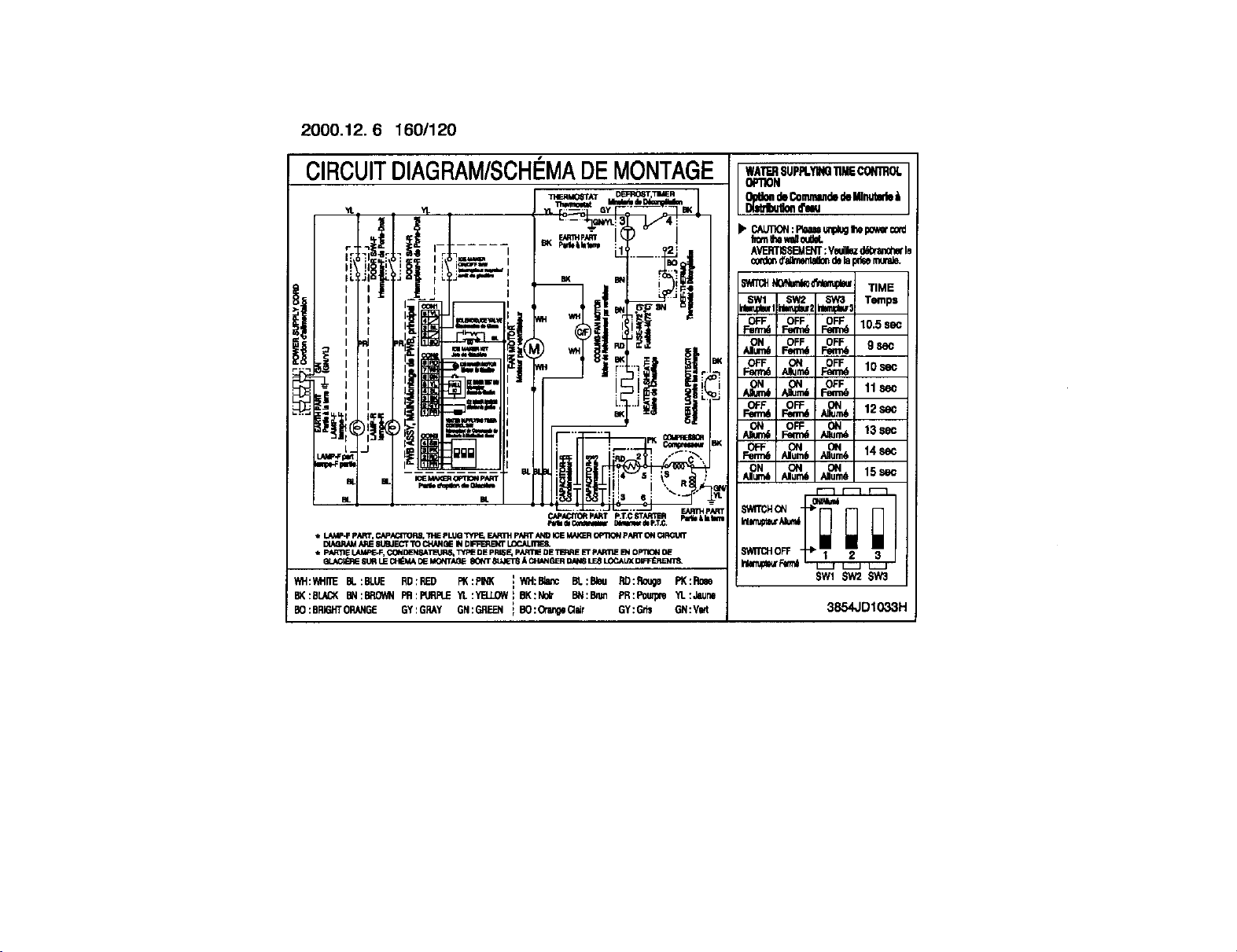
2000.12.6 160/120
CIRCUITDIAGRAM/SCH¢:MADEMONTAGE
31ERM0_TAT D_RO6T,TIMER
"/t
['8'1:I.......r-_ --I _,,'bW,_ LL:I _2' ,11
'_ r--'_ QyFL'--L]TaKJ
il,L!J----_- _ I!
!, !
IN_r=.=,, ,t I*" *".,_h,,_ "
I _ E o _.._ e_
. I :1,... I ;,. T ! r _]=_ I_L
'
I.J
Li_,_.F p_', P.,i_i,GITOBS,"1_1_PLtJG"PIPE+EAR_ pN4T N_D IGEMAIQROPTIONpr_IT _ _
BIi_R/_ AR_81J_JEC'rTO 1_/_I61E IN DIFFERB_ U3_.1_33_
pARTIE LAMFE-F, C4:t_ISATL=UR_ TY/_ DE pRISE, p,_RnE DE _ ET pARTIE _ OPTIGN OE
• ,.ACI_ 8t._ I.E CH_ _ MONTA_E 8G_rr 8tJ,IET8_ CIt_GER ON_ LE8LOCAL_DFR_EIIP&
WH:_III_ _L:BLUE RB:RED PK:pIt_ IWH:Bla_ _:elee RD:Ro_ge PK:Ro_
B(:SL/_ _N:BRO_NFR:P_PE YL:YBJ.OW_BK:No_ _:B_ PR:POu_ Yl.:Jsune
BO:BRI6h'TORANGEGY:GRAY GN:GREF..N_BO:Orar_Qcr GY:G_ GN:V_
=. Z ,'J
L..._
e_ai_ O_mw _ep,T_
{
WA'rF.RSUPPLYIN_11MECONIROL
OF_ON
• CAUIX_:Plea_Lmp_gI',epoe,_c=_d
f_omIhet_ ou_
AVERTISSEM_iT:V_Wlbzd6braa,_herle
NONmr,&_o'_tar,_ TIME
SWl SW2 SW3 Temps
_ _ lo._
ON OFF OFF g S_C
Alum6 Fem_ Fem_
_ _Nmt .O_ 11se_
_6 _6 14sec
Alum6 Allure6
SWlTCHOFF- -_ 3
SW_ $w2 5w3
3854JDlO33H
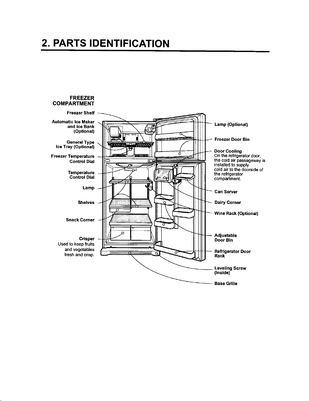
2. PARTS IDENTIFICATION
FREEZER
COMPARTMENT
Freezer Shelf
Automatic Ice Maker
and ice Bank
(Optional)
General Type
Ice Tray (Optional)
Freezer Temperature
Control Dial
Temperature
Control Dial
Lamp (Optional)
Freezer Door Bin
Door Cooling
On the refrigeratordoor,
the cold air passageway is
installedtosupply
coldair to the doorside of
the refrigerator
compartment.
Lamp
Shelves
Snack Corner
Crisper
Used to keep fruits
and vegetables
fresh and crisp.
Can Sewer
Dairy Corner
Wine Rack (Optional)
ustable
Door Bin
Rack
Screw
(inside)
Base Grille
3. DISASSEMBLY
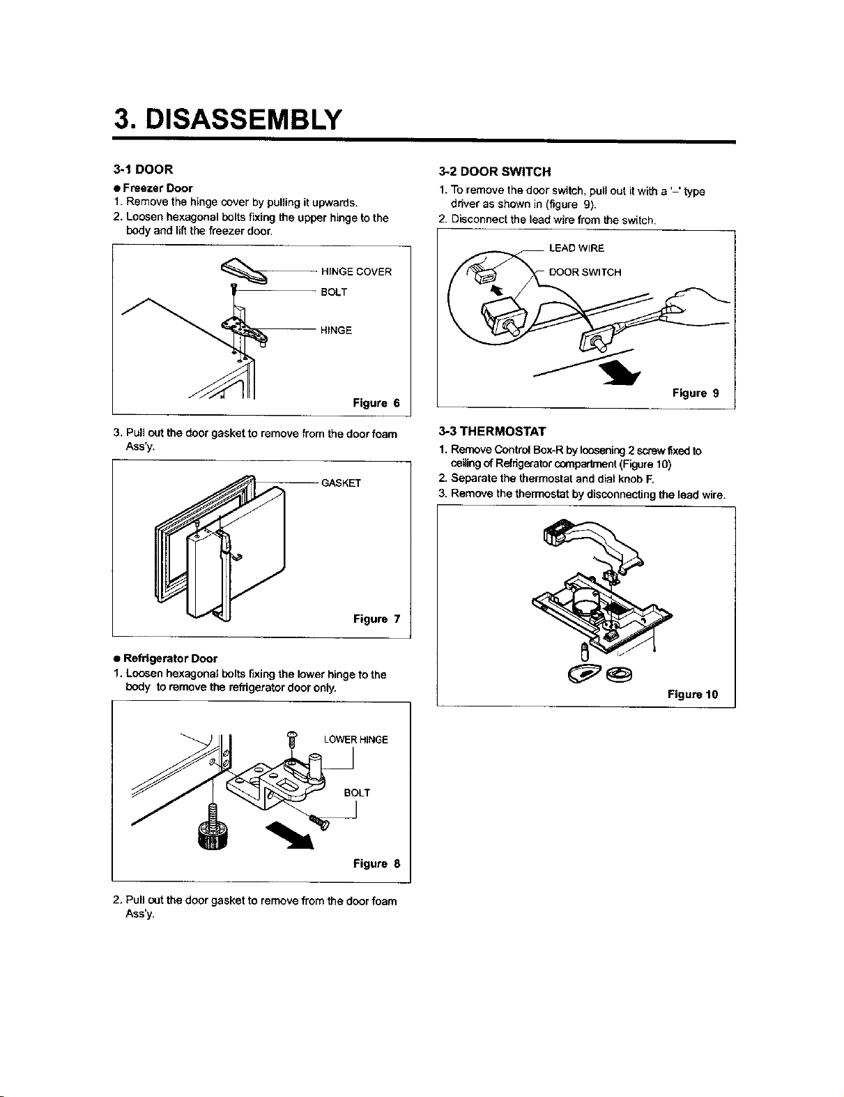
3-1 DOOR
• Freezer Door
1. Remove the hinge cover by pulling it upwards.
2. Loosen hexagonal bolts fixing the upper hinge to the
body and I_t the freezer door.
HINGE COVER
BOLT
HINGE
Figure 6
3. Pull out the door gasket to remove from the door foam
Ass'y.
GASKET
3-2 DOOR SWITCH
1. To remove the door swish, pull out it with a '-' type
driver as shown in (figure 9).
2. Disconnect the lead wire from the switch.
Figure 9
3-3 THERMOSTAT
1. Remove Control Box-R by loosening 2 screw fixed to
ceiling of Refdg_ator compadrnent (Figure 10)
2. Separate the thermostat and dial knob F,
3. Remove the thermostat by disconnecting the lead wire.
Figure 7
• Refrigerator Door
1. Loosen hexagonal bolts fixing the lower hinge to the
body to remove the refrigerator door only.
LOWER HINGE
Figure 8
2. Pull out the door gasket to remove from the door foam
Ass'y.
Figure 10
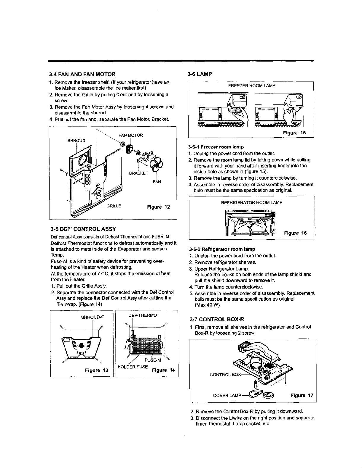
3.4 FAN AND FAN MOTOR
1. Remove the freezer sheff. (If your refrigerator have an
Ice Maker, disassemble the Ice maker first)
2. Remove the Gdlle by pulling it out and by loosening a
screw.
3. Remove the Fan Motor Assy by loosening 4 screws and
disassembta the shroud.
4. Pull out the fan end. separate the Fan Motor, Bracket.
SHROUD
3-6 LAMP
FREEZER ROOM LAMP
Figure t5
3-6.1 Freezer room lamp
1. Unplug the power cord from the outlet.
2. Remove the room lamp lid by taking down while pulling
it forward with your hand alter inserting finger into the
inside hale as shown in (figure 15).
3. Remove the lamp by turning it counterclockwise.
4. Assemble in reverse order of disassembly. Replacement
bulb must be the same specication as original.
Figure 12
3-5 DEF' CONTROL ASSY
Def controlAssyconsistsof Defrost Thermostatand FUSE-M.
Defrost Thermostat functions to defrost automatically and it
isattached to metal side of the Evaporator and senses
Temp.
Fuse-M is a kind of safety device for preventing over-
heating of the Heater when defrosting,
At the temperature of 77°C, it stops the emission of heat
from the Heater.
1. Pull out the Gdlle Ass'y.
2. Separate the connector connected with the Def Control
Assy and replace the Def Control Assy alter cutting the
Tie Wrap. (Figure 14)
SHROUD-F
DE_THERMO
FUSE-M
Figure 13
HOLDERFUSE
Figure 14
REFRIGERATOR ROOM LAMP
I_ Figure 16
3-6-2 Refrigerator room lamp
1. Unplug the power cord from the outlet.
2. Remove refrigerator shelves.
3. Upper Refrigerator Lamp.
Release the hooks on both ends of the lamp shield and
pull the shield downward to remove it.
4. Turn the lamp counterclockwise.
5. Assemble in reverse order of disassembly, Replacement
bulb must be the same specification as original.
(Max 40 W)
3-7 CONTROL BOX-R
1, First, remove all shelves in the refrigerator and Control
Box-R by loosening 2 screw,
CONTROl
COVER LAMP_@ Figure 17
2. Remove the Control Box-R by pulling it downward.
3. Disconnect the L/wire on the nght position and seperate
timer, themostat, Lamp socket, etc.
4. ADJUSTMENT
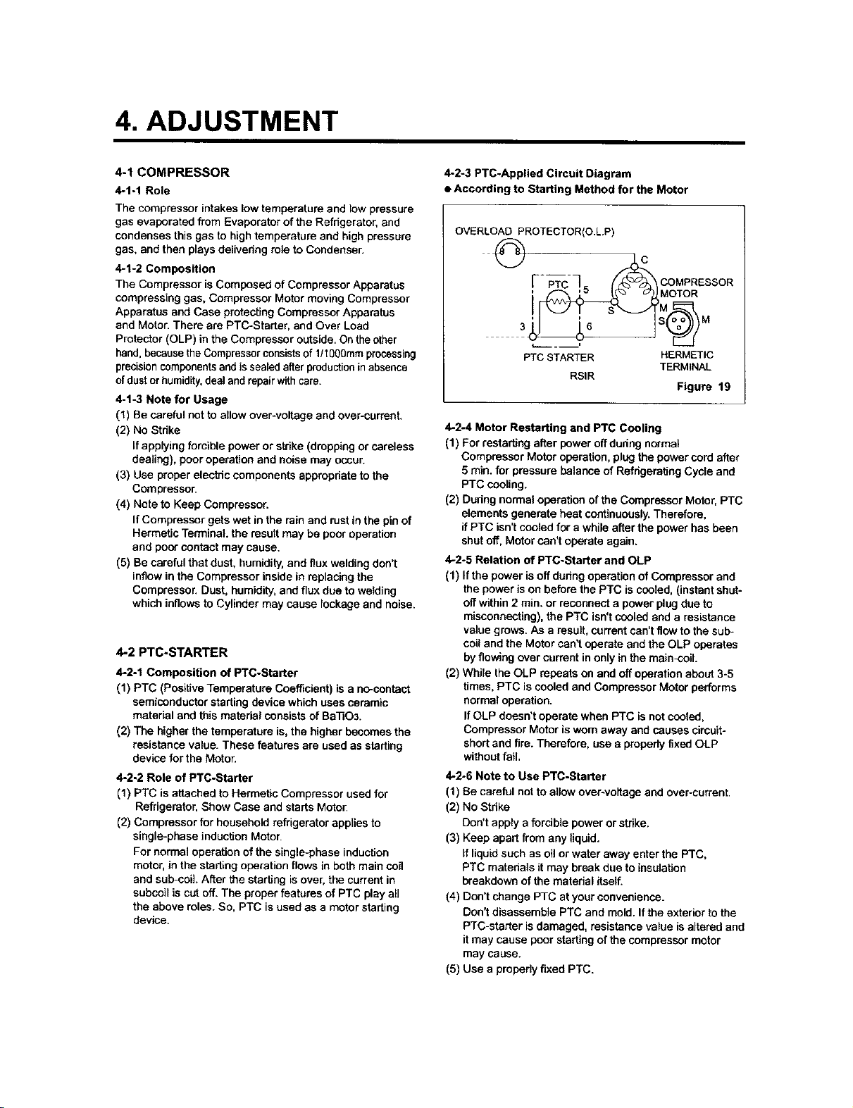
4-1 COMPRESSOR
4-1-1 Role
The compressor intakes low temperature and low pressure
gas evaporated from Evaporator of the Refrigerator, and
condenses this gas to high temperature and high pressure
gas, and then plays delivering role to Condenser.
4-1-2 Composition
The Compressor is Composed of Compressor Apparatus
compressing gas, Compressor Motor moving Compressor
Apparatus and Case protecting Compressor Apparatus
and Motor. There are PTC-Starter, and Over Load
Protector (OLP) in the Compressor outside. On the other
hand, because the Compressor consistsof 1/1000rnm processing
precisioncomponentsand is sealed after production in absence
of dust orhumidity,deal and repair with care.
4-1-3 Note for Usage
(1) Be careful not to allow over-voltage and over-current.
(2) No Strike
if applying forcible power or strike (dropping or careless
dealing), poor operation and noise may occur.
(3) Use proper electric components apprepdate to the
Compressor.
(4) Note to Keep Compressor.
If Compressor gets wet in the rain and rust in the pin of
Hermetic Terminal, the result may be poor operation
and poor contact may cause.
(5) Be careful that dust, humidity, and flux welding don't
inflow in the Compressor inside in replacing the
Compressor. Dust, humidity, and flax due to welding
which inflows to Cylinder may cause leckage and noise.
4-2 PTC-STARTER
4-2-1 Composition of PTC-Starter
(1) PTC (Positive Temperature Coefficient) is a no-contact
semiconductor starting device which uses ceramic
material and this material consists of Ba]]O3.
(2) The higher the temperature is, the higher becomes the
resistance value. These features are used as starting
device for the Motor.
4-2-2 Role of PTC-Starter
(1) PTC is attached to Hermetic Compressor used for
Refrigerator, Show Case and starts Motor.
(2) Compressor for household refrigerator applies to
single-phase induction Motor.
For normal operation of the single-phase induction
motor, in the starting operation flows in both main coil
and sub-coiL After the starting is over, the current in
subcoit is cut off. The proper features of PTC play all
the above roles. So, PTC is used as a motor starting
device.
4-2-3 PTC-Applied Circuit Diagram
• According to Starting Method for the Motor
OVERLOAD PROTECTOR(O.L.P)
_7_. C MPR S O
( < kMOoR SR
PTC STARTER HERMETIC
RSIR
4-2-4 Motor Restarting and PTC Cooling
(1) For restarting after power off dudng normal
Compressor Motor operation, plug the power card after
5 rain. for pressure balance of Refrigerating Cycle and
PTC cooling.
(2) During normal operation of the Compressor Motor, PTC
elements generate heat continuously. Therefore,
if PTC isn't cooled for a while after the power has been
shut off, Motor can't operate again,
4-2-5 Relation of PTC-Starter and OLP
(1) If the power is off dudng operation of Compressor and
the power is on before the PTC is cooled, (instant shut*
off within 2 min. or reconnect a power plug due to
misconnecting), the PTC isn't cooled and a resistance
value grows. As a result, current can't flow to the sub-
coil and the Motor can't operate and the OLP operates
by flowing over current in only in the main-coil.
(2) While the OLP repeats on and off operation about 3-5
times, PTC is cooled and Compressor Motor performs
normal operation.
If OLP doesn't operate when PTC is not cooled,
Compressor Motor is worn away and causes circuit-
short and fire. Therefore, use a property fixed OLP
without fail,
4-2-6 Note to Use PTC-Starter
(1) Be careful not to allow over*voltage and over-current.
(2) No Strike
Don't apply a forcible power or strike.
(3) Keep apart from any liquid.
if liquid such as oil or water away enter the PTC,
PTC materials it may break due to insulation
breakdown of the material itself.
(4) Don't change PTC at your convenience.
Don't disassemble PTC and mold. If the exterior to the
PTC-starter is damaged, resistance value is altered and
it may cause poor starting of the compressor motor
may cause.
(5) Use a properly fixed PTC.
TERMINAL
Figure 19
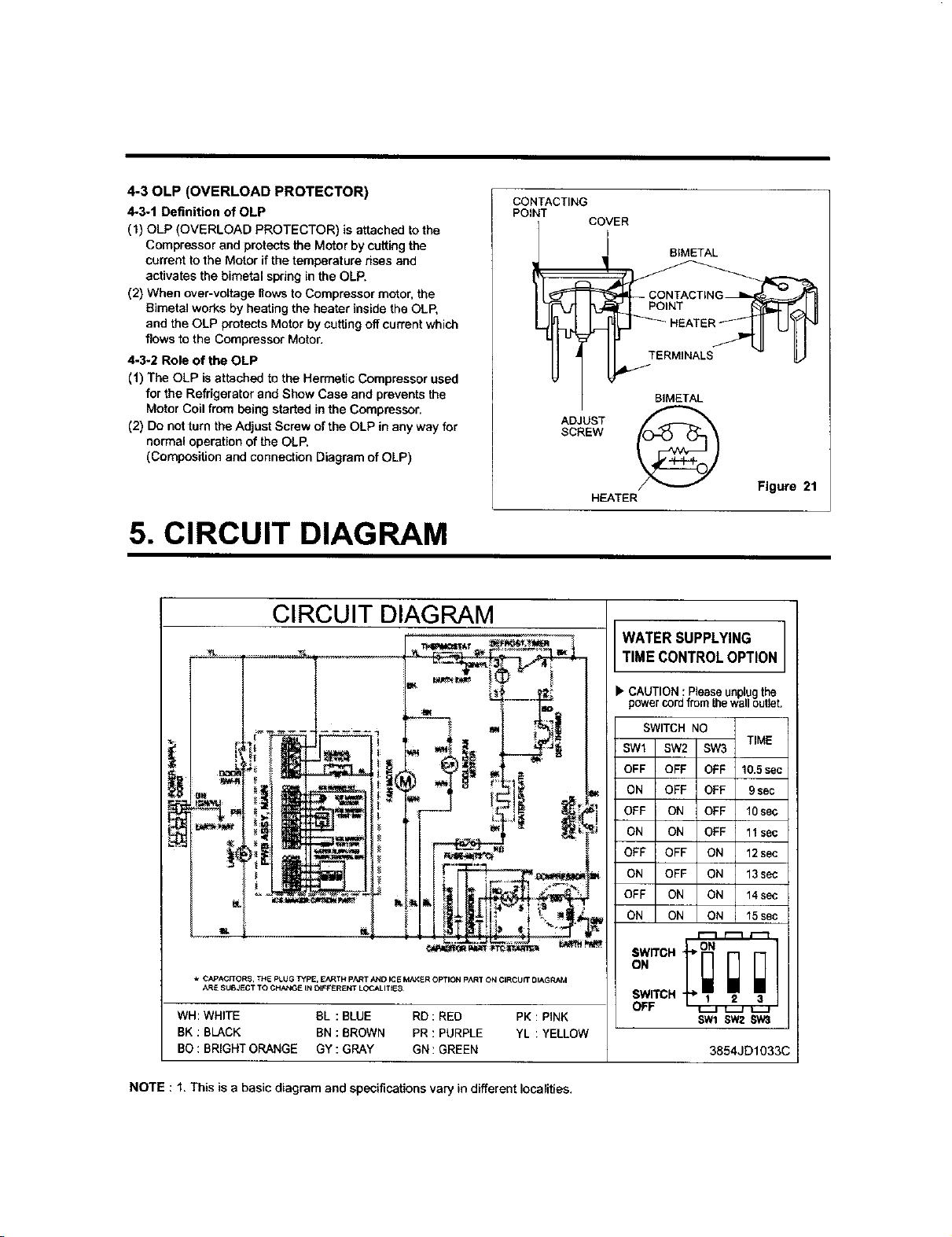
4-30LP (OVERLOAD PROTECTOR)
4-3.1 Definition of OLP
(1) OLP (OVERLOAD PROTECTOR) is attached to the
Compressor and protects the Motor by cutting the
current to the Motor if the temperature dses and
activates the bimetal swing in the OLP.
(2) When over-voltage flows to Compressor motor, the
Bimetal works by heath 9 the heater inside the OLP,
and the OLP protects Motor by cutting off current which
flows to the Compressor Motor.
4-3-2 Role of the OLP
(1) The OLP is attached to the Hermetic Compressor used
for the Refrigerator and Show Case and prevents the
Motor Coil from being started in the Compressor.
(2) Do not turn the Adjust Screw of the OLP in any way for
normal operation of the OLP,
(Composition and connection Diagram of OLP)
5. CIRCUIT DIAGRAM
CIRCUIT DIAGRAM
CONTACTING
POINT
_BIMETAL
SCREW
ADJUST
COVER
BIMETAL
HEATER
WATERSUPPLYING
TIMECONTROLOPTION
Figure 21
* CAPACITORS, THE PLUG TYPE, EARTH pART AND ICE MAKER OPTION PART ON CIRCUIT DIAGRAM
ARE 8UBaECT TO CHANG_ IN DIF_£REN¥ LOCALITIES
WH: WHITE BL : BLUE RD : RED PK : PINK
BK : BLACK BN : BROWN PR : PURPLE YL : YELLOW
BO : BRIGHT ORANGE GY : GRAY GN : GREEN
NOTE : 1. This is a basic diagram and specifications vary in different localities.
CAUTION : Please unplugthe
powercordfrom the walloutlet.
SWITCH NO
SW1 SW2 SW3
OFF OFF OFF 10.5se
ON OFF OFF 9 sec
OFF ON OFF 10 se(
ON ON OFF 11 se(
OFF OFF ON 12se(
ON OFF ON 13 se_
OFF ON ON 14se(
ON ON ON 15se(
SWITCH 2 a
OFF _ v._r _
SW1 SW2 SW3
TIME
3854JD1033C
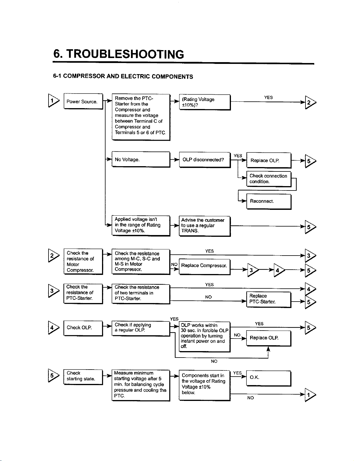
6. TROUBLESHOOTING
6-1 COMPRESSOR AND ELECTRIC COMPONENTS
[_ Power Source.
[_ Check the
resistance of
Motor
Compressor.
._ Remove the PTC-
Starter from the
Compressor and
measure the voltage
between Terminal C of
Compressor and
Terminals 5 or 6 of PTC.
No Voltage. OLP disconnected? Replace OLP.
Applied voltage isn't
in the range of Rating to use a regular _-I__
Voltage +10%. TRANS.
Check the resistance
among M_3, S-C and
M-S in Motor
Compressor. .o a eCo 0 o.or
.__ (RatingVoltage YES
±10%)? I "l_
Check connection
condition.
r%_
[_ Check the
[_ Check OLP.
[_ Check
resistance of
PTC-Starter.
starting state.
of two terminals in Replace
PTC-Starter. NO }_ PTC-Starter.
C ckthe s nceI YESI
YES
a regular OLR _, 130 sec. in forcible OLP
I I I operation by turning Replace OLP.
I I instant power on and
II°".
NO
I-'_ starting voltage alter 5 O.K.
I I rain. for balancing cycle _ I Voltage +10%
Measure minimum _ Components start in _[
| pressure and cooling the I I below.
/ PTC I I I .o
I the voltage of Rating
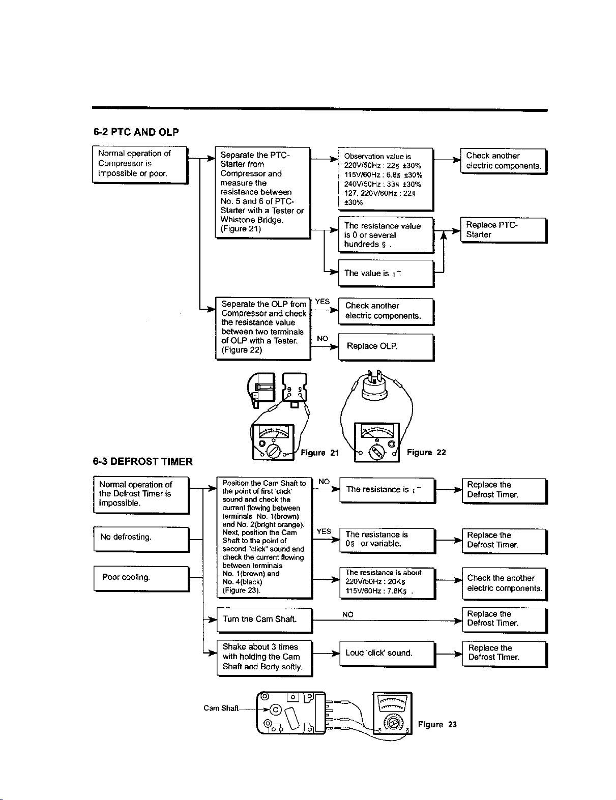
6-2 PTC AND OLP
Compressor is
I Normaloperationof
impossible or poor,
__ Separate the PTC- ._
Starter from
Compressor and
measure the
resistance between
No. 5 and 6 of PTC-
Starter with a Tester or
(Figure 21)
r
!
Observation voiueis
220V/50Hz : 228 ±30%
115VI60Hz : 6.88 ±30%
240V!50Hz : 335 -+30%
127, 220V/60Hz : 228
-+30%
The resistance value _l
is 0 or several
hundreds _ .
/
Check another Ielectric components.
Replace PTC-
Starter
6-3 DEFROST TIMER
Normal operation of __
the Defrost Timer is "_
/mposs b e.
No defrosting. F
Poor cooling.
Whistone Bndge. __
Compressor and check_ electric components. I
the resistance value | I
between two terminals I r
I Separata the OLP from _ yI:S_._[ Check another
of OLP with a Tester. NLNOj I
(Figure 22) _ Replace OLP.
Position the Cam Shaft to
the point of first 'dick'
sound and check the
current flowing between
terminals No. 1(brown)
and No. 2(bright orange),
Next, position the Cam
Shaft to the point of
second "click" sound and
check the current nowing
between terminals
No. 1(brown) and
No. 4(black)
(Figure 23).
The va]ue is i "_
--_ The resistance is z-
.._ The resistance is
___ The resistance is about
0_ orvariable,
220V/5OHz :20K_
115V/60Hz : 7.8K$ .
I
DReefpl_sctth_eer" I
I_ ;ep_°a_tethneer I
i_ heckthe another I
electric components.
Tum the Cam Shaft. I NO
with holding the Cam Loud 'click' sound.
._ Shake about 3 times I_
Shaft and Body softly.
P D
" DRefp_°actetheer" I
I_ Replace theDefrost Timer. I
 Loading...