

LG LRTG2011BS, LRTG2011BK, LRTG1811BS Owner’s Manual
SERVICING PRECAUTIONS
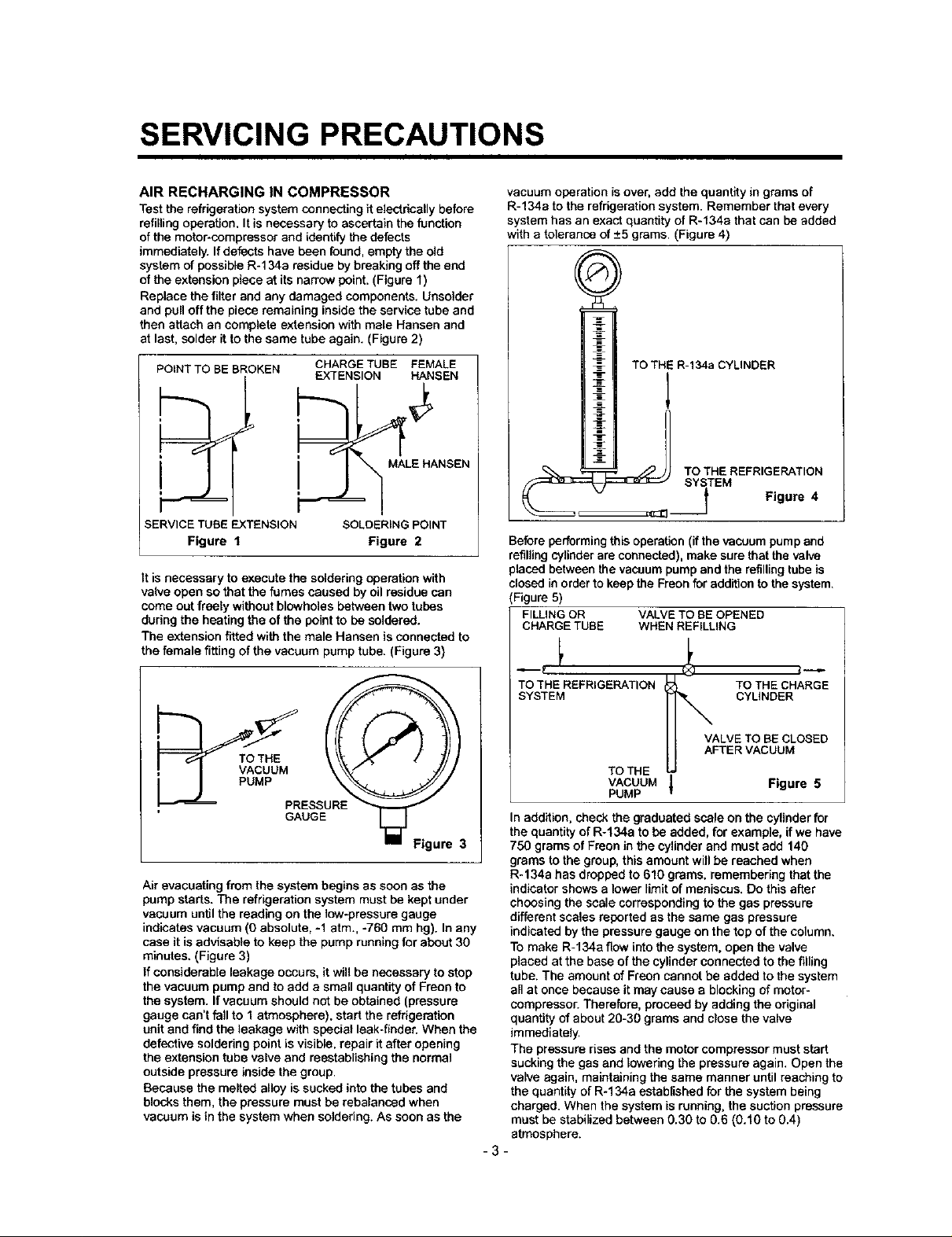
AIR RECHARGING IN COMPRESSOR
Test the refrigeration system connecting it electrically before
refilling operation. It is necessary to ascertain the function
of the motor-compressor and identify the defects
immediately. If defects have been found, empty the old
system of possible R-134a residue by breaking off the end
of the extension piece at its narrow point. (Figure 1)
Replace the filter and any damaged components. Unso}der
and pull off the piece remaining inside the service tube and
then attach an complete extension with male Hansen and
at last, solder it to the same tube again. (Figure 2)
POINT TO BE BROKEN
SERVICE TUBE EXTENSION
Figure 1
It is necessary to execute the soldering operation with
valve open so that the fumes caused by oil residue can
come out freely without blowholes between two tubes
during the heating the of the point to be soldered.
The extension fitted with the male Hansen is connected to
the female fitting of the vacuum pump tube. (Figure 3)
CHARGE TUBE FEMALE
EXTENSION HANSEN
MALE HANSEN
SOLOERING POINT
Figure 2
vacuum operation is over, add the quantity in grams of
R-134a to the refrigeration system. Remember that every
system has an exact quantity of R-134e that can be added
with a tolerance of _+5grams. (Figure 4)
TO THi R-134a CYLINDER
?s %REFR'GERAT'ON
___ Figure 4
Before performing this operation (if the vacuum pump and
refilling cylinder are connected), make sure that the valve
placed between the vacuum pump and the refilling tube is
closed in order to keep the Freon for addition to the system.
(Figure 5)
FILLING OR VALVE TO BE OPENED
CHARGE TUBE WHEN REFILLING
GAUGE
Figure 3
Air evacuating from the system begins as soon as the
pump starts. The refrigeration system must be kept under
vacuum until the reading on the low-pressure gauge
indicates vacuum (0 absolute, -1 atm., -760 mm hg). In any
case it is advisable to keep the pump running for about 30
minutes. (Figure 3)
If considerable leakage occurs, it will be necessary to stop
the vacuum pump and to add a small quantity of Freon to
the system. If vacuum should not be obtained (pressure
gauge can't fall to 1 atmosphere), start the refrigeration
unit and find the leakage with special leek-finder. When the
defective soldering point is visible, repair it after opening
the extension tube valve and reestablishing the normal
outside pressure inside the group.
Because the melted alloy is sucked into the tubes and
blocks them, the pressure must be rebalanced when
vacuum is in the system when soldering. As soon as the
TO THE REFRIGERATION TO THE CHARGE
SYSTEM CYLINDER
VALVE TO BE CLOSED
AFTER VACUUM
TO THE
VACUUM J Figure 5
PUMP
In addition, check the graduated scale on the cylinder for
the quantity of R-134a to be added, for example, if we have
750 grams of Freon in the cylinder and must add 140
grams to the group, this amount will be reached when
R-134a has dropped to 610 grams, remembering that the
indicator shows a lower limit of meniscus. Do this after
choosing the scale corresponding to the gas pressure
different scales reported as the same gas pressure
indicated by the pressure gauge on the top of the column.
To make R-134a flow into the system, open the valve
placed at the base of the cylinder connected to the filling
tube. The amount of Freon cannot be added to the system
all at once because it may cause e blocking of motor-
compressor. Therefore, proceed by adding the original
quantity of about 20-30 grams and close the valve
immediately.
The pressure rises and the motor compressor must start
sucking the gas and [owerfog the pressure again. Open the
valve again, maintaining the same manner until reaching to
the quantity of R-134a established for the system being
charged. When the system is running, the suction pressure
must be stabilized between 0.30 to 0.6 (0.10 to 0.4)
atmosphere.
-3-
T
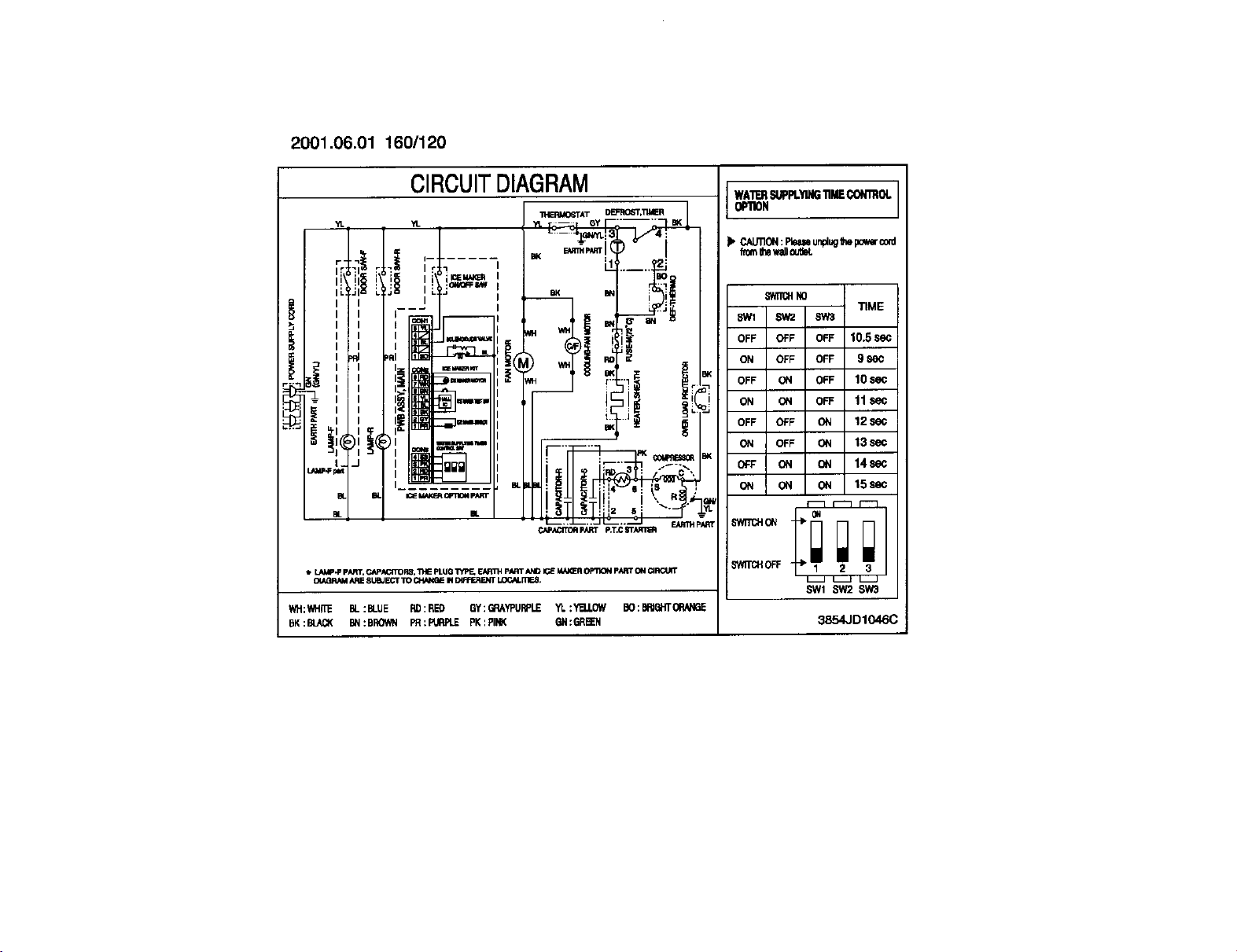
2001.06.01 160/120
CIRCUITDIAGRAM
YL "d. ..... GY ..... BK
11.II_MO6TA T DEP'RO6T*_
WATERSUPPt.YING_i CONmOL
OPIION
I. CAUIlON:Pimmunplug1hepo_rco_l
hetnIhawaJI_JtlK
,_i_i_il I_ i=_ , .o,
IL!JI L I [ BK BN "'1i
I I I----- I = '_JlL_'
r m
,, II ....
-
ij#!i#,, : '
_" ' l:r
m_ IL
LAMP.FpART,CAP_CtTOP,g."i_lEpLUG"i_lP_EAR1?4PART/_lD I_ MA_R OPT1ONpARTONCIRC_
OtAQRAM/_JE8UeJECTTO CHNK_ PIDIFFERE_IT_rnEB,
WH:WH_ BL:BLUE RD:RED GY:G_AYPURPLE YI. :Y_.OW BO: E_4GHT0RANGE
BK:BL_X BN:BROWN PR:PURPLE PK:PINK GN:GREEN 3854JD1046C
--. _. EMITHpId_T
CA_._ pARTp,T,C8T_1_
u-wrrcHN0
8Wl SW2 SW3
OFF OFF OFF 10.5 SeC
ON OFF OFF 9 86_
OFF ON OFF 10 sec
ON ON OFF 11 sec
OFF OFF ON 12
ON OFF ON 13 sec
OFF ON ON 14sec
ON ON ON 15sec
SWITCH(3N -÷_
8WI _ $W3
TIME

2. PARTS IDENTIFICATION
FREEZER
COMPARTMENT
Freezer Shelf
General Type
Ice Tray
Ice Cube Box
Freezer Temperature
REFRIGERATOR
COMPARTMENT
Temperature
Control Dial
Freezer Door Bin
Door Cooling
On the refrigerator door,
the cold air passageway is
installedto supply
coldair to the doorside of
the refrigerator
compartment.
Lamp
Shelves
Snack Corner
Crisper
Used tokeep _ui_
and vegetables
fresh and cdsp.
Base Grille
Pushthe grille toward
the refrigerator
until itsnaps
into place.
Can Server
Dairy Corner
Adjustable
Door Bin
Refrigerator Door
Rack
g Screw
(Inside)
-5-
3. DISASSEMBLY
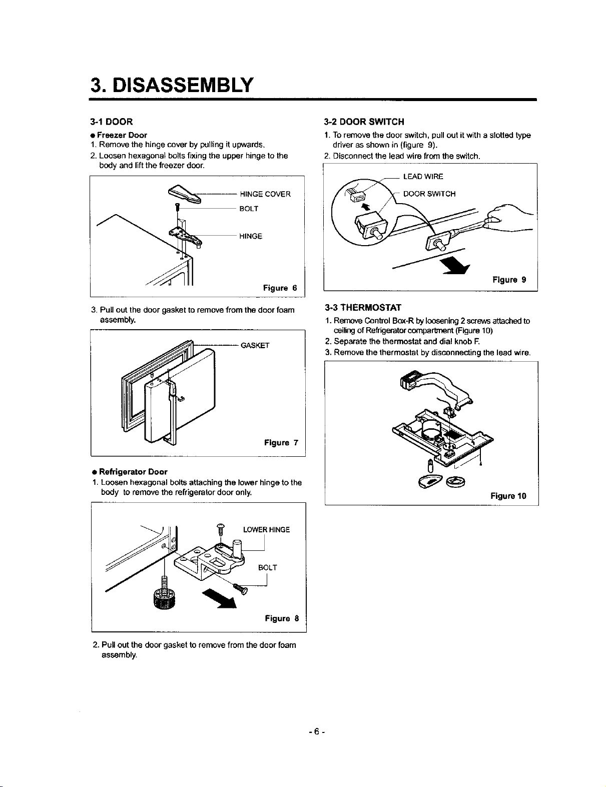
3-1 DOOR
• Freezer Door
1, Remove the hinge cover by pulling it upwards,
2. Loosen hexagonal bolts fixing the upper hinge to the
body and lift the freezer door.
BOLT
HINGE
HINGE COVER
Figure 6
3. Pull out the door gasket to remove from the door foam
assembly.
GASKET
3-2 DOOR SWITCH
1. To remove the door switch, pull out it with a slotted type
driver as shown in (figure 9).
2. Disconnect the lead wire from the switch.
LEAD WIRE
DOOR SWITCH
Figure 9
3-3 THERMOSTAT
1. Remove Control Box-R by loosening 2 screwsattached to
ceilingof Refrigerator comparlment (Figure 1O)
2. Separate the thermostat and dial knob F.
3. Remove the thermostat by disconnecting the lead wire.
Figure 7
• Refrigerator Door
1. Loosen hexagonal bolts attaching the lower hinge to the
body to removethe refdgeratordoor only.
LOWER HINGE
Figure 8
2. Pull out the door gasket to remove from the door foam
assembly.
Figure 10
-6-
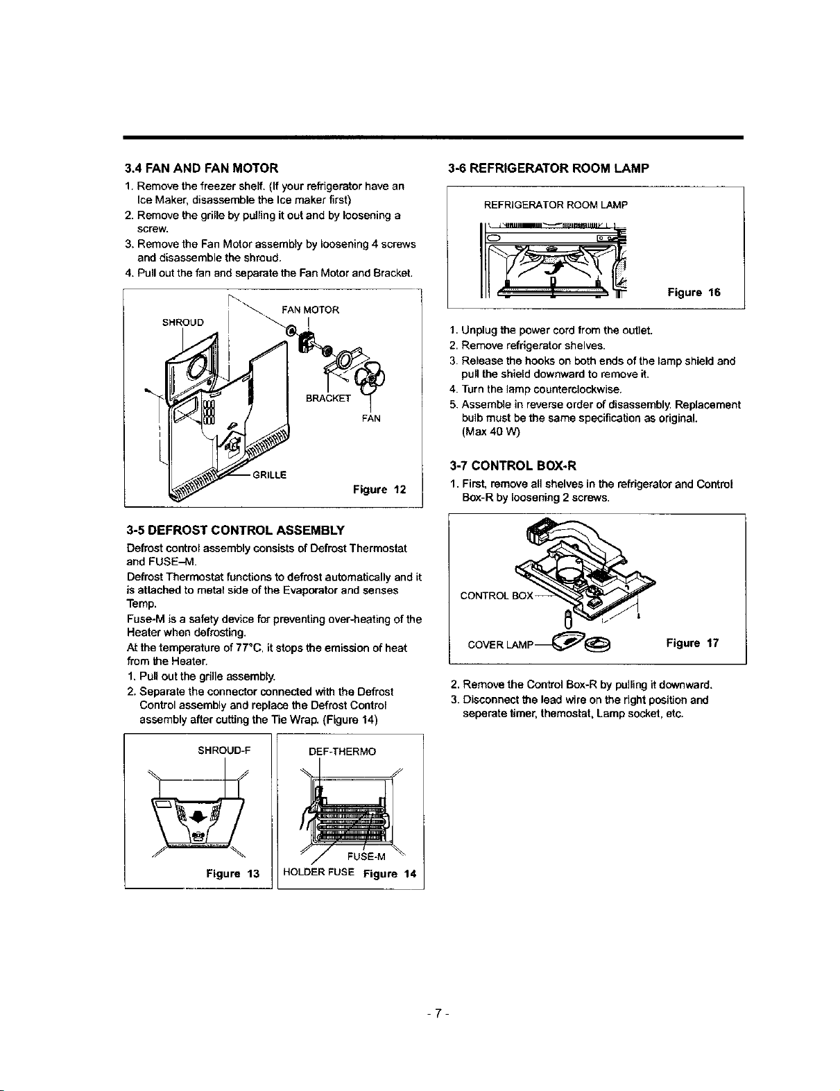
3.4 FAN AND FAN MOTOR
1. Remove the freezer shelf. (If your refrigerator have an
Ice Maker, disassemble the Ice maker first)
2. Remove the grille by pulling it out and by loosening a
screw.
3. Remove the Fan Motor assembly by loosening 4 screws
and disassemble the shroud.
4. Pull out the fan and separate the Fan Motor and Bracket.
SHROUD
[_"\FAN MOTOR
FAN
3-6 REFRIGERATOR ROOM LAMP
REFRIGERATOR ROOM LAMP
Figure 16
1. Unplug the power cord from the outlet.
2. Remove refrigerator shelves.
3. Release the hooks on both ends of the lamp shield and
pull the shield downward to remove it.
4. Turn the lamp counterclockwise.
5. Assemble in reverse order of disassembly. Replacement
bulb must be the same specification as original.
(Max 40 W)
- GRILLE
Figure 12
3-5 DEFROST CONTROL ASSEMBLY
Defrost control assembly consists of Defrost Thermostat
and FUSE-M.
Defrost Thermostat functions to defrost automatically and it
is attached to metal side of the Evaporator and senses
Temp.
Fuse-M is a safety device for preventing over-heating of the
Heater when defrosting.
At the temperature of 77°C, it stops the emission of heat
from the Heater.
1. Pull out the grille assembly.
2. Separate the connector connected with the Defrost
Control assembly and replace the Defrost Control
assembly after cutting the Tie Wrap. (Figure 14)
SHROUD-F
Figure 13
DEF_HERMO
FUSE-M
HOLDER FUSE Figure 14
3-7 CONTROL BOX-R
1. First, remove all shelves in the refrigerator and Control
Box-R by loosening 2 screws.
COVER LAMP_@ Figure 17
2. Remove the Control Boxer by pulling it downward.
3. Disconnect the lead wire on the right position and
seperate timer, themostat, Lamp socket, etc.
-7-
 Loading...