

Page 1
CAUTION
BEFORE SERVICING THE UNIT,
READ THE SAFETY PRECAUTIONS IN THIS MANUAL.
REFRIGERATOR
SERVICE MANUAL
http://biz.lgservice.com
MODEL : LRTBC1825T
LRTBC2025T
COLOR: TITANIUM
Page 2

SAFETY PRECAUTIONS....................................................................................................................................................... 2
SERVICING PRECAUTIONS.................................................................................................................................................. 3
SPECIFICATIONS................................................................................................................................................................... 4
PARTS IDENTIFICATION....................................................................................................................................................... 5
DISASSEMBLY.................................................................................................................................................................... 6-7
DOOR................................................................................................................................................................................... 6
DOOR SWITCH.................................................................................................................................................................... 6
THERMOSTAT..................................................................................................................................................................... 6
FAN AND FAN MOTOR........................................................................................................................................................ 7
DEFROST CONTROL ASSEMBLY...................................................................................................................................... 7
LAMP.................................................................................................................................................................................... 7
CONTROL BOX-R................................................................................................................................................................ 7
ADJUSTMENT........................................................................................................................................................................ 8
COMPRESSOR.................................................................................................................................................................... 8
POSITIVE TEMPERATURE COEFFICIENT-STARTER....................................................................................................... 8
OVERLOAD PROTECTOR.................................................................................................................................................. 9
CIRCUIT DIAGRAM................................................................................................................................................................ 9
TROUBLESHOOTING..................................................................................................................................................... 10-15
COMPRESSOR AND ELECTRIC COMPONENTS ........................................................................................................... 10
POSITIVE TEMPERATURE COEFFICIENT AND OVERLOAD PROTECTOR................................................................. 11
DEFROST TIMER .............................................................................................................................................................. 11
OTHER ELECTRIC COMPONENTS ................................................................................................................................. 12
SERVICE DIAGNOSIS CHART.......................................................................................................................................... 13
REFRIGERATING CYCLE............................................................................................................................................ 14-15
OPERATION PRINCIPLE AND REPAIR METHOD OF ICE MAKER ............................................................................ 16-27
EXPLODED VIEW .......................................................................................................................................................... 28-31
REPLACEMENT PARTS LIST............................................................................................................................................ 32-
CONTENTS
- 2 -
Please read the following instructions before servicing your
refrigerator.
1. Check the refrigerator for current leakage.
2. To prevent electric shock, unplug before servicing.
3. Always check line voltage and amperage.
4. If you use any kind of appliance, check regular current,
voltage, and capacity.
5. Don't touch metal products in the freezer with wet
hands. This may cause frostbite.
6. Prevent water from following onto electric elements in
the mechanical parts.
7. Close the top door before opening the bottom door.
Otherwise, you might hit your head when you stand up.
8. When tilting the refrigerator, remove any materials on
the refrigerator, especially the thin plates (ex. Glass
shelf or books.)
9. When servicing the evaporator, wear cotton gloves.
This is to prevent injuries from the sharp evaporator
fins.
10. Leave the disassembly of the refrigerating cycle to a
specialized service center. The gas inside the circuit
may pollute the environment.
SAFETY PRECAUTIONS
Page 3
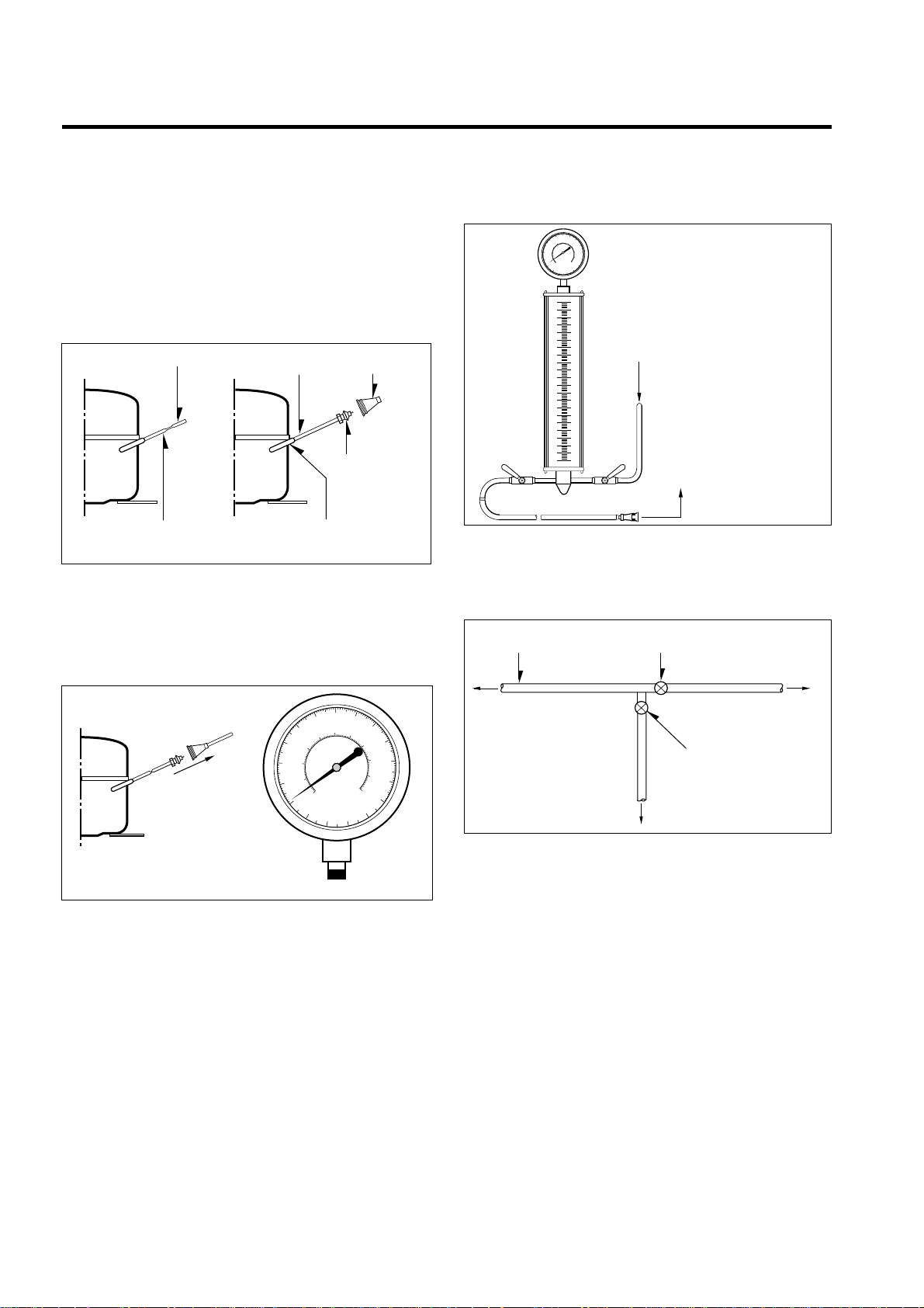
AIR RECHARGING IN COMPRESSOR
Test the refrigeration system connecting it electrically before
refilling operation. It is necessary to ascertain the function
of the motor-compressor and identify the defects
immediately. If defects have been found, empty the old
system of possible R-134a residue by breaking off the end
of the extension piece at its narrow point. (Figure 1)
Replace the filter and any damaged components. Unsolder
and pull off the piece remaining inside the service tube and
then attach an complete extension with male Hansen and
at last, solder it to the same tube again. (Figure 2)
It is necessary to execute the soldering operation with
valve open so that the fumes caused by oil residue can
come out freely without blowholes between two tubes
during the heating the of the point to be soldered.
The extension fitted with the male Hansen is connected to
the female fitting of the vacuum pump tube. (Figure 3)
Air evacuating from the system begins as soon as the
pump starts. The refrigeration system must be kept under
vacuum until the reading on the low-pressure gauge
indicates vacuum (0 absolute, -1 atm., -760 mm hg). In any
case it is advisable to keep the pump running for about 30
minutes. (Figure 3)
If considerable leakage occurs, it will be necessary to stop
the vacuum pump and to add a small quantity of Freon to
the system. If vacuum should not be obtained (pressure
gauge can't fall to 1 atmosphere), start the refrigeration
unit and find the leakage with special leak-finder. When the
defective soldering point is visible, repair it after opening
the extension tube valve and reestablishing the normal
outside pressure inside the group.
Because the melted alloy is sucked into the tubes and
blocks them, the pressure must be rebalanced when
vacuum is in the system when soldering. As soon as the
vacuum operation is over, add the quantity in grams of
R-134a to the refrigeration system. Remember that every
system has an exact quantity of R-134a that can be added
with a tolerance of ±5 grams. (Figure 4)
Before performing this operation (if the vacuum pump and
refilling cylinder are connected), make sure that the valve
placed between the vacuum pump and the refilling tube is
closed in order to keep the Freon for addition to the system.
(Figure 5)
In addition, check the graduated scale on the cylinder for
the quantity of R-134a to be added, for example, if we
have 750 grams of Freon in the cylinder and must add 140
grams to the group, this amount will be reached when
R-134a has dropped to 610 grams, remembering that the
indicator shows a lower limit of meniscus. Do this after
choosing the scale corresponding to the gas pressure
different scales reported as the same gas pressure
indicated by the pressure gauge on the top of the column.
To make R-134a flow into the system, open the valve
placed at the base of the cylinder connected to the filling
tube. The amount of Freon cannot be added to the system
all at once because it may cause a blocking of motorcompressor. Therefore, proceed by adding the original
quantity of about 20-30 grams and close the valve
immediately.
The pressure rises and the motor compressor must start
sucking the gas and lowering the pressure again. Open the
valve again, maintaining the same manner until reaching to
the quantity of R-134a established for the system being
charged. When the system is running, the suction pressure
must be stabilized between 0.30 to 0.6 (0.10 to 0.4)
atmosphere.
SERVICING PRECAUTIONS
- 3 -
POINT TO BE BROKEN
SERVICE TUBE EXTENSION
CHARGE TUBE
EXTENSION
FEMALE
HANSEN
MALE HANSEN
SOLDERING POINT
Figure 1 Figure 2
TO THE
VACUUM
PUMP
PRESSURE
GAUGE
Figure 3
TO THE R-134a CYLINDER
TO THE REFRIGERATION
SYSTEM
Figure 4
FILLING OR
CHARGE TUBE
VALVE TO BE OPENED
WHEN REFILLING
VALVE TO BE CLOSED
AFTER VACUUM
TO THE CHARGE
CYLINDER
TO THE REFRIGERATION
SYSTEM
TO THE
VACUUM
PUMP
Figure 5
Page 4
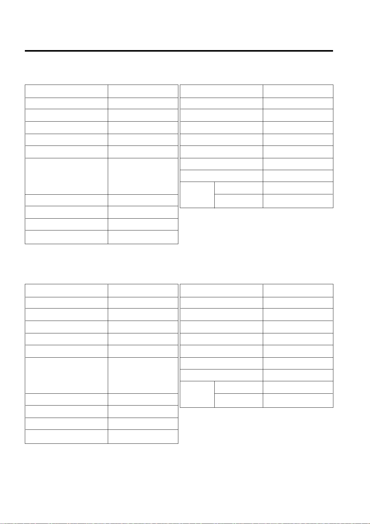
1. SPECIFICATIONS
- 4 -
ITEMS SPECIFICATIONS
DOOR DESIGN All Rounded
DIMENSIONS (mm)
754.5 X 735 X 1732 (W X D X H
)
NET WEIGHT (kg) 90
COOLING SYSTEM Fan Cooling
TEMPERATURE CONTROL Knob Dial
Full Automatic
DEFROSTING SYSTEM Heater Defrost
With a Timer
DOOR FINISH Vinyl Coated Metal
HANDLE TYPE Bar
INNER CASE ABS Resin
INSULATION Polyurethane Foam
ITEMS SPECIFICATIONS
VEGETABLE TRAY Transparent Drawer Type
COMPRESSOR PTC Starting Type
EVAPORATOR Fin Tube Type
CONDENSER Wire Condenser
REFRIGERANT R-134a (155 g)
LUBRICATING OIL ISO10 (280 cc)
DEFROSTING DEVICE SHEATH HEATER
FREEZER 25 W
LAMP
REFRIGERATOR 40 W
1. Ref. No.: LRTBC1825T
ITEMS SPECIFICATIONS
DOOR DESIGN All Rounded
DIMENSIONS (mm)
754.5 X 788 X 1732 (W X D X H
)
NET WEIGHT (kg) 93
COOLING SYSTEM Fan Cooling
TEMPERATURE CONTROL Knob Dial
Full Automatic
DEFROSTING SYSTEM Heater Defrost
With a Timer
DOOR FINISH Vinyl Coated Metal
HANDLE TYPE Bar
INNER CASE ABS Resin
INSULATION Polyurethane Foam
ITEMS SPECIFICATIONS
VEGETABLE TRAY Transparent Drawer Type
COMPRESSOR PTC Starting Type
EVAPORATOR Fin Tube Type
CONDENSER Wire Condenser
REFRIGERANT R-134a (155 g)
LUBRICATING OIL ISO10 (280 cc)
DEFROSTING DEVICE SHEATH HEATER
FREEZER 25 W
LAMP
REFRIGERATOR 40 W
2. Ref. No.: LRTBC2025T
Page 5
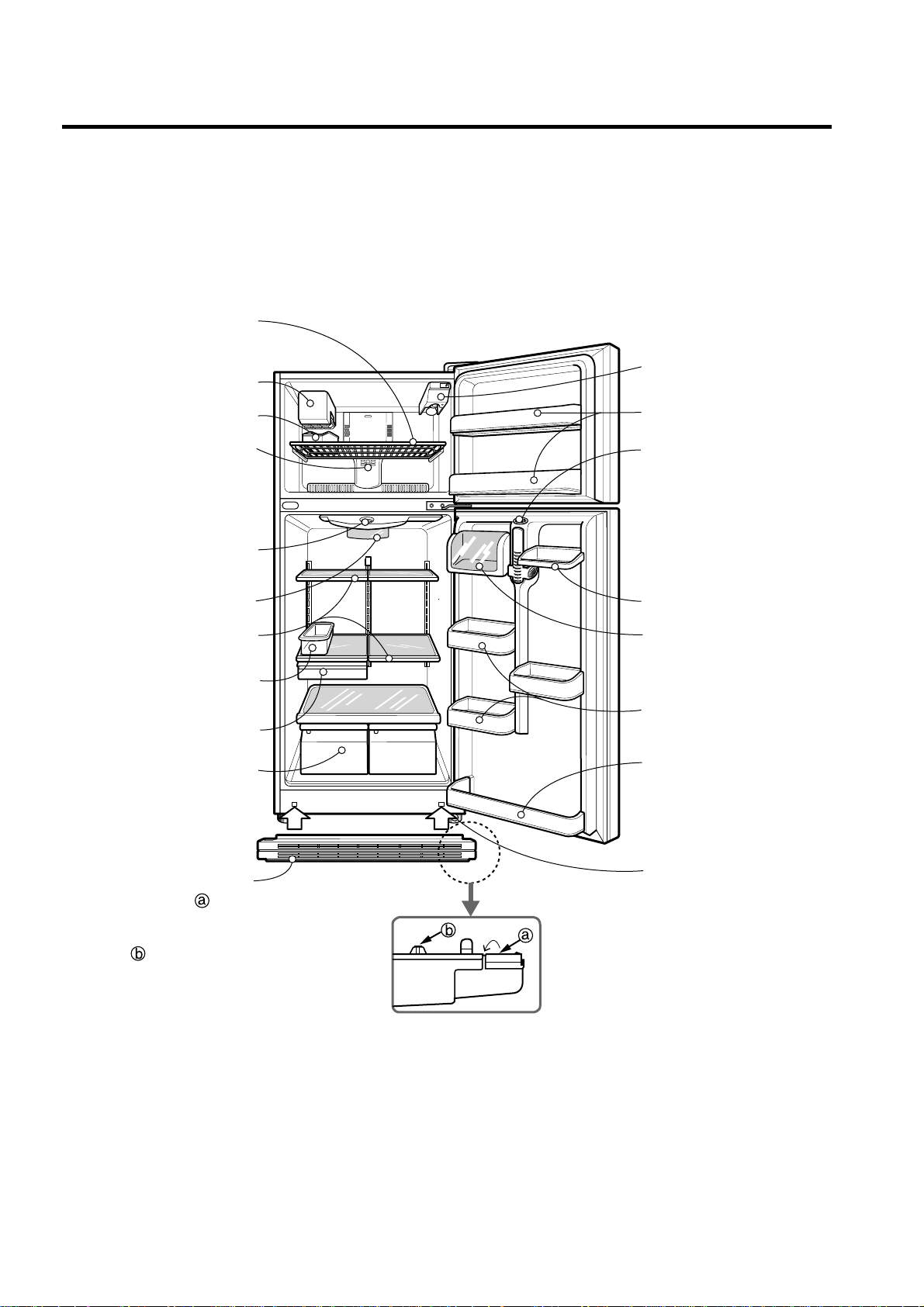
2. PARTS IDENTIFICATION
- 5 -
Automatic Ice Maker
Ice Cube Box
FREEZER
COMPARTMENT
REFRIGERATOR
COMPARTMENT
Freezer Temperature
Control Dial
Freezer Shelf
Door Cooling
On the refrigerator door,
the cold air passageway is
installed to supply
cold air to the doorside of
the refrigerator
compartment.
Temperature
Control Dial
Lamp
Shelves
Egg Box
(option)
Snack Corner
Crisper
Used to keep fruits
and vegetables
fresh and crisp.
Freezer Door Bin
Lamp
Refrigerator Door
Rack
Can Server
Adjustable
Door Bin
Leveling Screw
(Inside)
Dairy Corner
Base Grille
1. Bend down.
2. Push the grille toward the
refrigerator.
3. <Three protecting
parts> should be beneath
the bottom plate while
pushing the grille.
Page 6
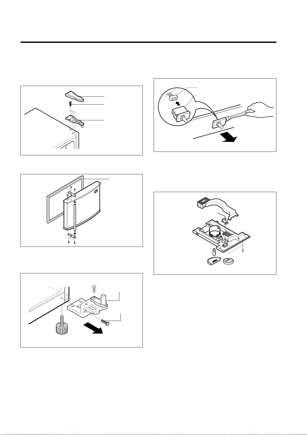
3-1 DOOR
● Freezer Door
1. Remove the hinge cover by pulling it upwards.
2. Loosen hexagonal bolts fixing the upper hinge to the
body and lift the freezer door.
3. Pull out the door gasket to remove from the door foam
assembly.
● Refrigerator Door
1. Loosen hexagonal bolts attaching the lower hinge to the
body to remove the refrigerator door only.
2. Pull out the door gasket to remove from the door foam
assembly.
3-2 DOOR SWITCH
1. To remove the door switch, pull out it with a slotted type
driver as shown in (figure 9).
2. Disconnect the lead wire from the switch.
3-3 THERMOSTAT
1. Remove Control Box-R by loosening 2 screws attached to
ceiling of Refrigerator compartment (Figure 10)
2. Separate the thermostat and dial knob F.
3. Remove the thermostat by disconnecting the lead wire.
3. DISASSEMBLY
- 6 -
BOLT
HINGE
HINGE COVER
Figure 6
GASKET
Figure 7
LOWER HINGE
BOLT
Figure 8
DOOR SWITCH
LEAD WIRE
Figure 9
Figure 10
Page 7
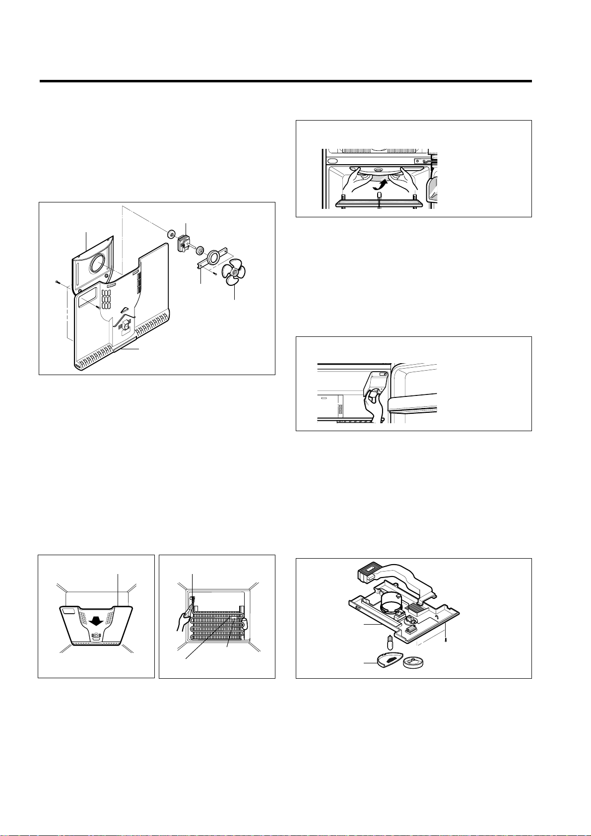
3-4 FAN AND FAN MOTOR
1. Remove the freezer shelf. (If your refrigerator have an
Ice Maker, disassemble the Ice maker first)
2. Remove the grille by pulling it out and by loosening a
screw.
3. Remove the Fan Motor assembly by loosening 4 screws
and disassemble the shroud.
4. Pull out the fan and separate the Fan Motor and Bracket.
3-5 DEFROST CONTROL ASSEMBLY
Defrost control assembly consists of Defrost Thermostat
and FUSE–M.
Defrost Thermostat functions to defrost automatically and it
is attached to metal side of the Evaporator and senses
Temp.
Fuse-M is a safety device for preventing over-heating of
the Heater when defrosting.
At the temperature of 77°C, it stops the emission of heat
from the Heater.
1. Pull out the grille assembly.
2. Separate the connector connected with the Defrost
Control assembly and replace the Defrost Control
assembly after cutting the Tie Wrap. (Figure 14)
3-6 LAMP
3-6-1 Refrigerator room lamp
1. Unplug the power cord from the outlet.
2. Remove refrigerator shelves.
3. Release the hooks on both ends of the lamp shield and
pull the shield downward to remove it.
4. Turn the lamp counterclockwise.
5. Assemble in reverse order of disassembly. Replacement
bulb must be the same specification as original.
(Max 40 W)
3-6-2 Freezer room lamp
1. Unplug refrigerator or disconnect power.
2. Reach behind light shield to remove bulb.
3. Replace bulb with a 25-watt appliance bulb.
4. Plug in refrigerator or reconnect power.
3-7 CONTROL BOX-R
1. First, remove all shelves in the refrigerator and Control
Box-R by loosening 2 screws.
2. Remove the Control Box-R by pulling it downward.
3. Disconnect the lead wire on the right position and
seperate timer, themostat, Lamp socket, etc.
- 7 -
FAN
BRACKET
SHROUD
GRILLE
FAN MOTOR
Figure 12
SHROUD-F
Figure 13
DEF-THERMO
FUSE-M
HOLDER FUSE
Figure 14
REFRIGERATOR ROOM LAMP
Figure 16-1
Figure 16-2
CONTROL BOX
COVER LAMP
Figure 17
FREEZER ROOM LAMP
Page 8
4-1 COMPRESSOR
4-1-1 Role
The compressor intakes low temperature and low pressure
gas evaporated from evaporator of the refrigerator, and
condenses this gas to high temperature and high pressure
gas, and then plays delivering role to condenser.
4-1-2 Composition
The compressor includes overload protection. The PTC
starter and OLP (overload protector) are outside the
compressor. Since the compressor is manufactured to
tolerances of 1 micron, and is sealed in a dust - and
moisture - free environment, use extreme caution when
repairing it.
4-1-3 Note for Usage
(1) Be careful not to allow over-voltage and over-current.
(2) No Strike
If applying forcible power or strike (dropping or careless
handling), poor operation and noise may occur.
(3) Use proper electric components appropriate to the
Compressor.
(4) Note to Keep Compressor.
If Compressor gets wet in the rain and rust in the pin of
Hermetic Terminal, the result may be poor operation
and poor contact may cause.
(5) Be careful that dust, humidity, and welding flux don't
contaminate the compressor inside when replacing the
Compressor. Dust, humidity, and flux due to welding
which contaminates the cylinder may cause lockage
and noise.
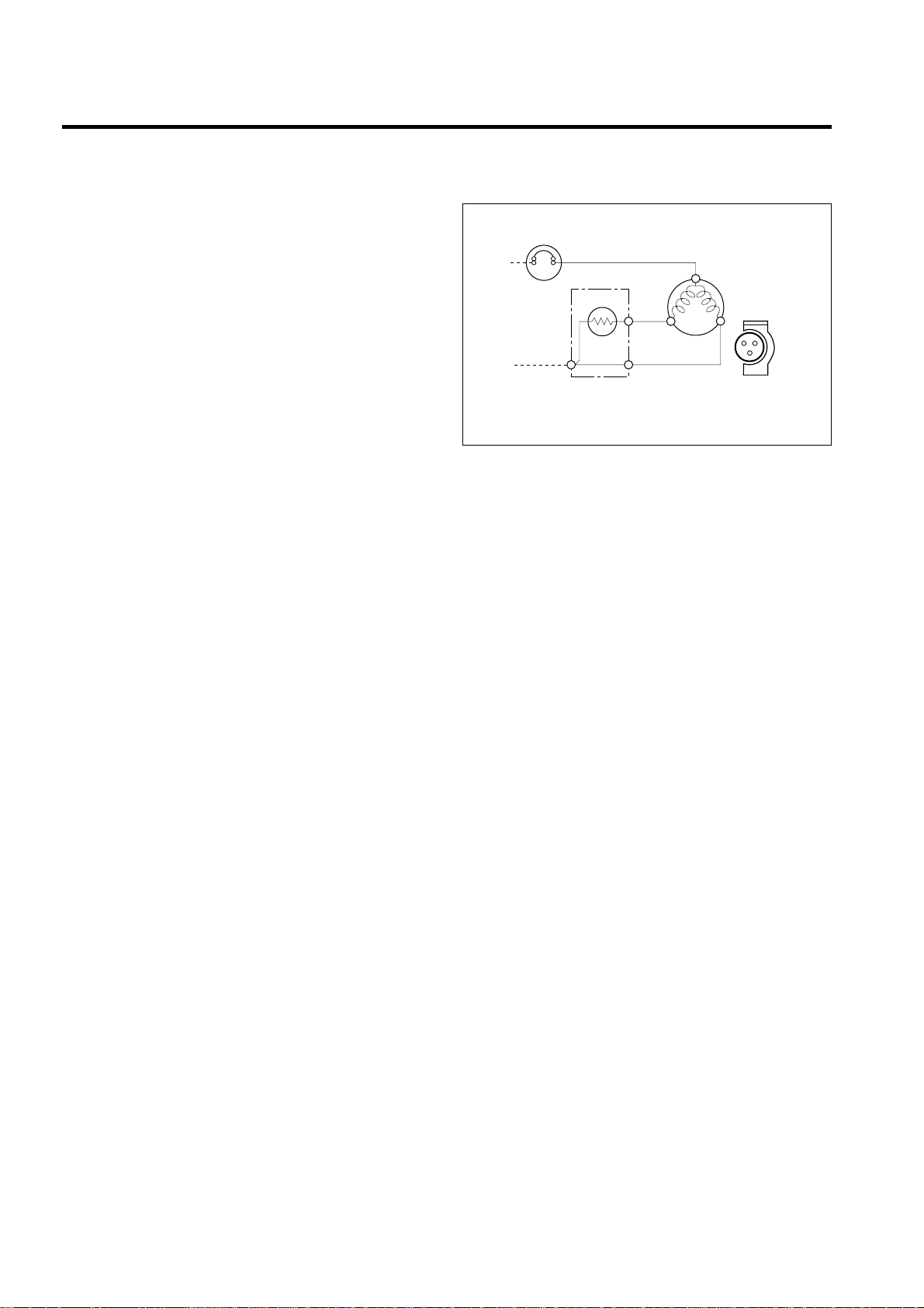
4-2 PTC-STARTER
4-2-1 Composition of PTC-Starter
(1) PTC (Positive Temperature Coefficient) is a no-contact
semiconductor starting device which uses ceramic
material consisting of BaTiO
3.
(2) The higher the temperature is, the higher the resistance
value. These features are used as starting device for
the Motor.
4-2-2 Role of PTC-Starter
(1) PTC is attached to Hermetic Compressor used for
Refrigerator, Show Case, and starting Motor.
(2) Compressor for household refrigerator applies to
single-phase induction Motor.
For normal operation of the single-phase induction
motor, in the starting operation flows in both main coil
and sub-coil. After the starting is over, the current in
subcoil is cut off. The proper features of PTC play all
the above roles. So, PTC is used as a motor starting
device.
4-2-3 PTC-Applied Circuit Diagram
● According to Starting Method for the Motor
4-2-4 Motor Restarting and PTC Cooling
(1) For restarting after power off during normal
Compressor Motor operation, plug the power cord after
5 min. for pressure balance of Refrigerating Cycle and
PTC cooling.
(2) During normal operation of the Compressor Motor, PTC
elements generate heat continuously. Therefore,
if PTC isn't cooled for a while after the power has been
shut off, the motor will not restart.
4-2-5 Relation of PTC-Starter and OLP
(1) If the power is off during operation of Compressor and
the power is on before the PTC is cooled, (instant shutoff within 2 min. or unplugging and reconnecting), the
PTC isn't cooled and a resistance value grows. As a
result, current can't flow to the sub-coil, the Motor can't
operate, and the OLP operates by flowing over current
in only in the main-coil.
(2) While the OLP repeats on and off operation about 3-5
times, PTC is cooled and Compressor Motor performs
normal operation.
If OLP doesn't operate when PTC is not cooled,
Compressor Motor is worn away and causes circuitshort and fire. Therefore, always use a properly
attached OLP.
4-2-6 Note to Use PTC-Starter
(1) Be careful not to allow over-voltage and over-current.
(2) Do not strike
Don't apply a forcible power or strike.
(3) Keep apart from any liquid.
If liquid, such as oil or water away enters the PTC,
PTC materials may fail due to insulation breakdown of
the material itself.
(4) Don't change PTC at your convenience.
Don't disassemble PTC and case. If the exterior to the
PTC-starter is damaged, resistance value is altered and
it may cause poor starting of the compressor motor
may cause.
(5) Use a properly attached PTC.
4. ADJUSTMENT
- 8 -
PTC STARTER
HERMETIC
TERMINAL
COMPRESSOR
MOTOR
C
M
S
M
3
6
5
S
PTC
OVERLOAD PROTECTOR(O.L.P)
RSIR
Figure 19
Page 9
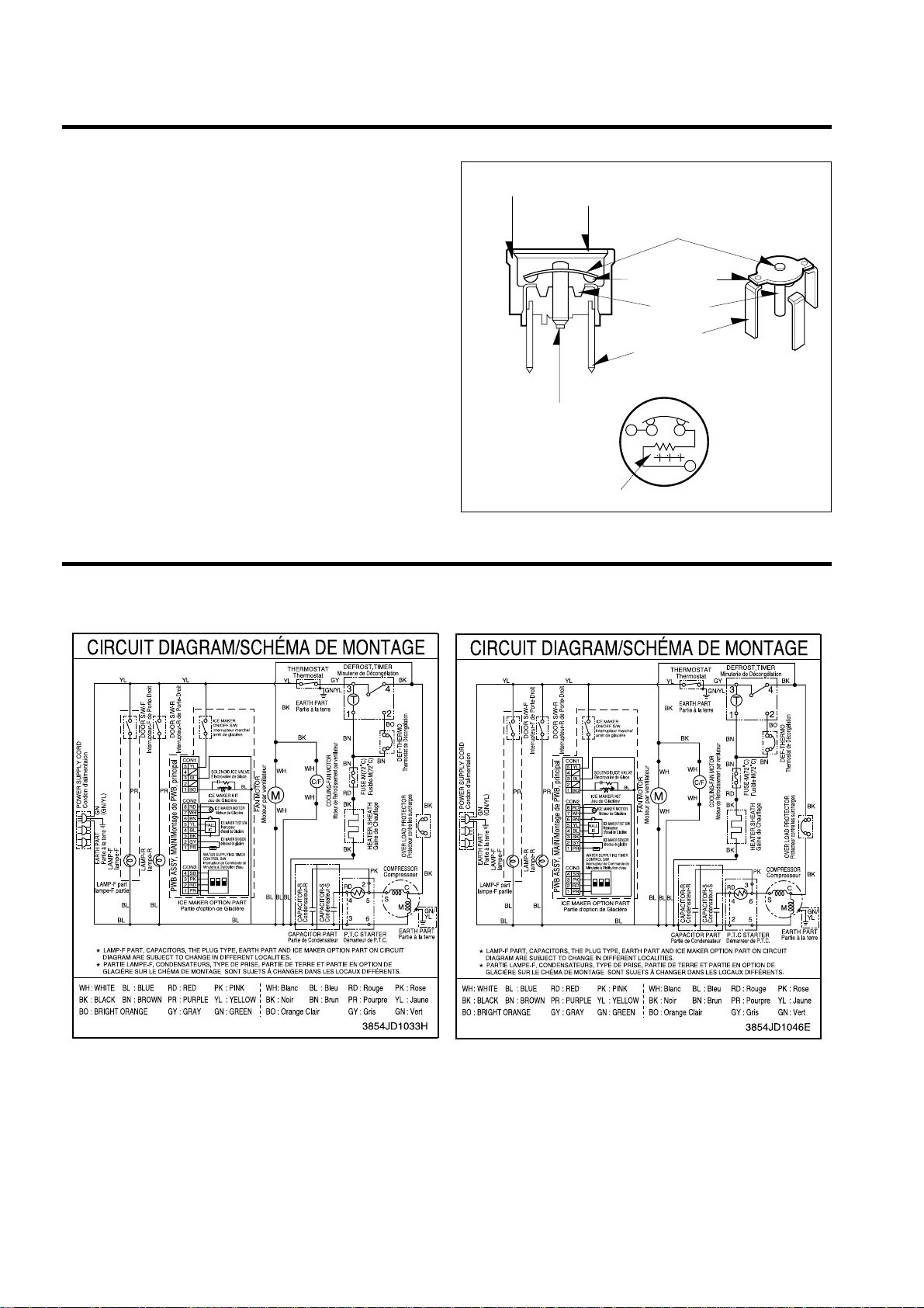
4-3 OLP (OVERLOAD PROTECTOR)
4-3-1 Definition of OLP
(1) OLP (OVERLOAD PROTECTOR) is attached to the
Compressor and protects the Motor by cutting the
current to the Motor if the temperature rises and
activates the bimetal spring in the OLP.
(2) When over-voltage flows to Compressor motor, the
Bimetal works by heating the heater inside the OLP,
and the OLP protects Motor by cutting off current which
flows to the Compressor Motor.
4-3-2 Role of the OLP
(1) The OLP is attached to the Hermetic Compressor used
for the Refrigerator and prevents the Motor Coil from
being started in the Compressor.
(2) Do not turn the Adjust Screw of the OLP in any way for
normal operation of the OLP.
(Composition and connection diagram of OLP)
- 9 -
5. CIRCUIT DIAGRAM
CONTACTING
POINT
COVER
BIMETAL
CONTACTING
POINT
HEATER
TERMINALS
ADJUST
SCREW
HEATER
BIMETAL
Figure 21
Ref. No.: LRTBC1825T Ref. No.: LRTBC2025T
Page 10
6. TROUBLESHOOTING
- 10 -
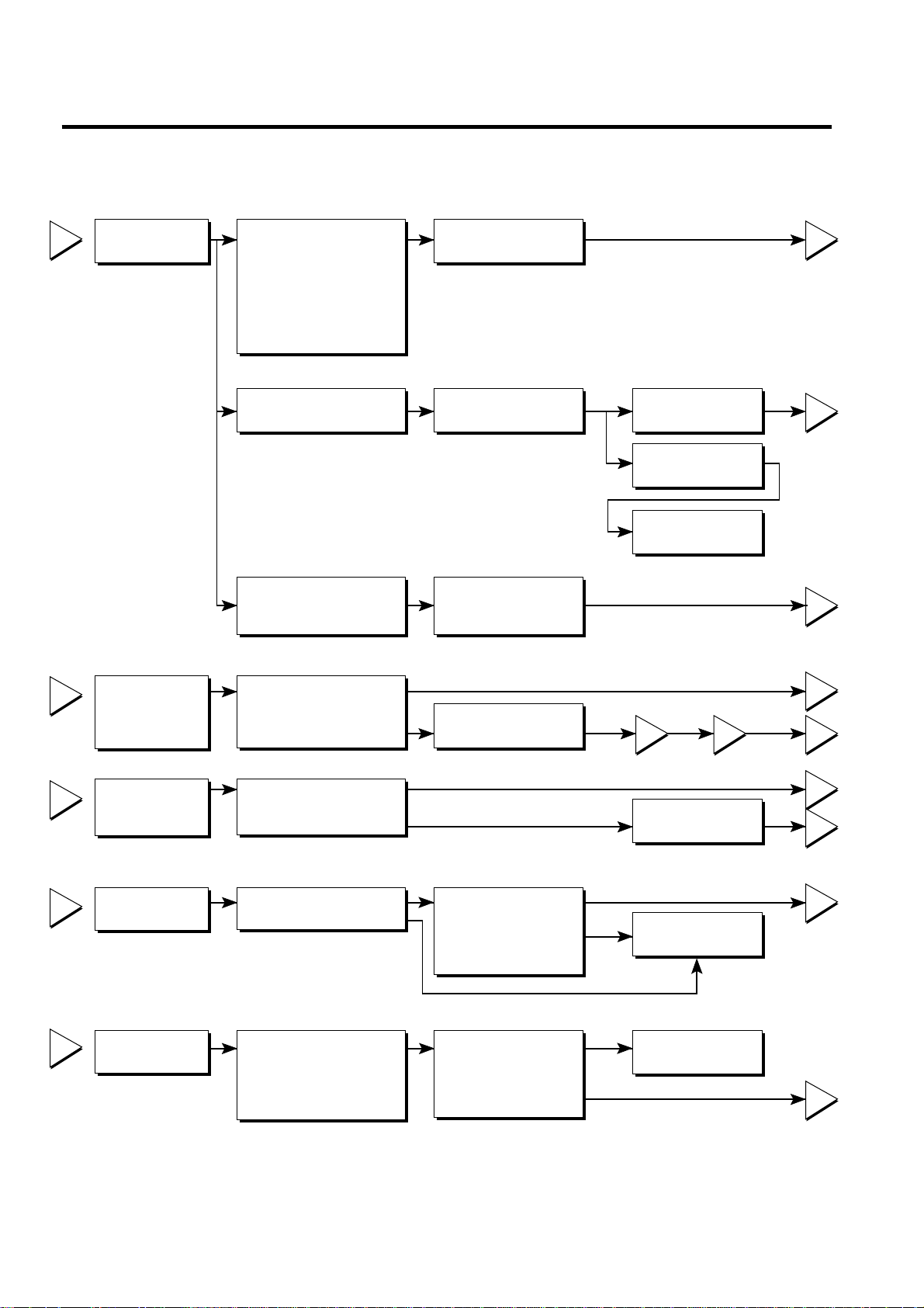
6-1 COMPRESSOR AND ELECTRIC COMPONENTS
1
2
3
4
5
2
5
5
3
5
4
5
5
1
43
YES
YES
YES
YES
NO
NO
YES
YES
YES
NO
NO
NO
Power Source.
No Voltage.
(Rating Voltage
±10%)?
Replace OLP.
Reconnect.
Replace
PTC-Starter.
Replace OLP.
O.K.
Check connection
condition.
OLP disconnected?
Advise the customer
to use a regular
transformer.
Replace Compressor.
OLP works within
30 sec. in forcible OLP
operation by turning
instant power on and
off.
Components start in
the voltage of Rating
Voltage ±10%
below.
Applied voltage isn't
in the range of Rating
Voltage ±10%.
Remove the PTCStarter from the
Compressor and
measure the voltage
between Terminal C of
Compressor and
Terminals 5 or 6 of PTC.
Check the resistance
among M-C, S-C and
M-S in Motor
Compressor.
Check the resistance
of two terminals in
PTC-Starter.
Check if applying
a regular OLP.
Measure minimum
starting voltage after 5
min. for balancing cycle
pressure and cooling the
PTC.
Check the
resistance of
Motor
Compressor.
Check the
resistance of
PTC-Starter.
Check OLP.
Check
starting state.
Page 11
- 11 -
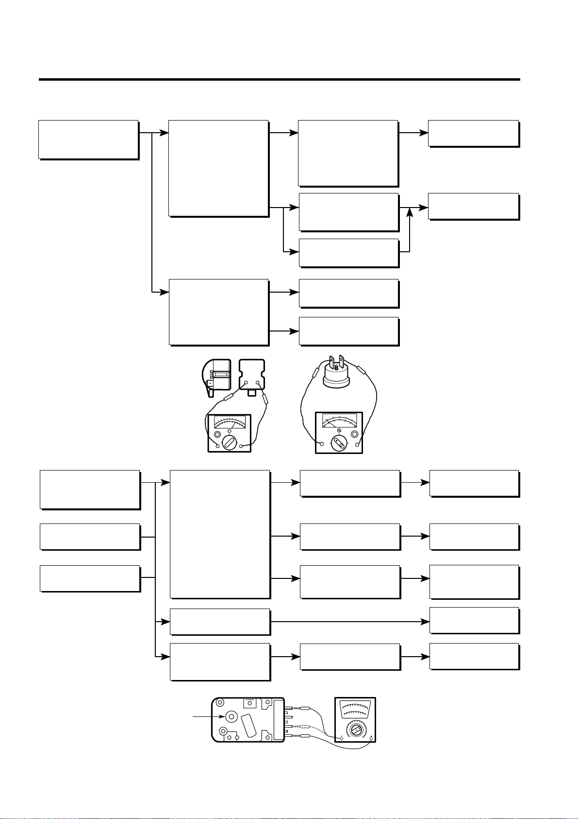
6-2 PTC AND OLP
65
YES
NO
NO
YES
NO
Cam Shaft
Normal operation of
Compressor is
impossible or poor.
Separate the PTCStarter from
Compressor and
measure the
resistance between
No. 5 and 6 of PTCStarter with a Tester or
Wheatstone Bridge.
(Figure 21)
Separate the OLP from
Compressor and check
the resistance value
between two terminals
of OLP with a Tester.
(Figure 22)
Observation value is
220V/50Hz : 22Ω±30%
115V/60Hz : 6.8Ω±30%
240V/50Hz : 33Ω±30%
127, 220V/60Hz : 22Ω
±30%
The resistance value
is 0 or several
hundred Ω.
The value is ∞.
Check another
electric components.
Replace OLP.
Check another
electric components.
Replace PTCStarter
Figure 21
Figure 22
Figure 23
Normal operation of
the Defrost Timer is
impossible.
No defrosting.
Poor cooling.
Position the Cam Shaft to
the point of first click
sound and check the
current flowing between
terminals No. 1(brown)
and No. 2(bright orange).
Next, position the Cam
Shaft to the point of
second click sound and
check the current flowing
between terminals
No. 1 (brown) and
No. 4 (black)
(Figure 23).
Turn the Cam Shaft.
Shake about 3 times
with holding the Cam
Shaft and Body softly.
The resistance is ∞.
The resistance is
0Ω or variable.
The resistance is about
220V/50Hz : 20KΩ
115V/60Hz : 7.8KΩ
Loud click sound.
Replace the
Defrost Timer.
Replace the
Defrost Timer.
Replace the
Defrost Timer.
Check the another
electric components.
Replace the
Defrost Timer.
6-3 DEFROST TIMER
Page 12
- 12 -
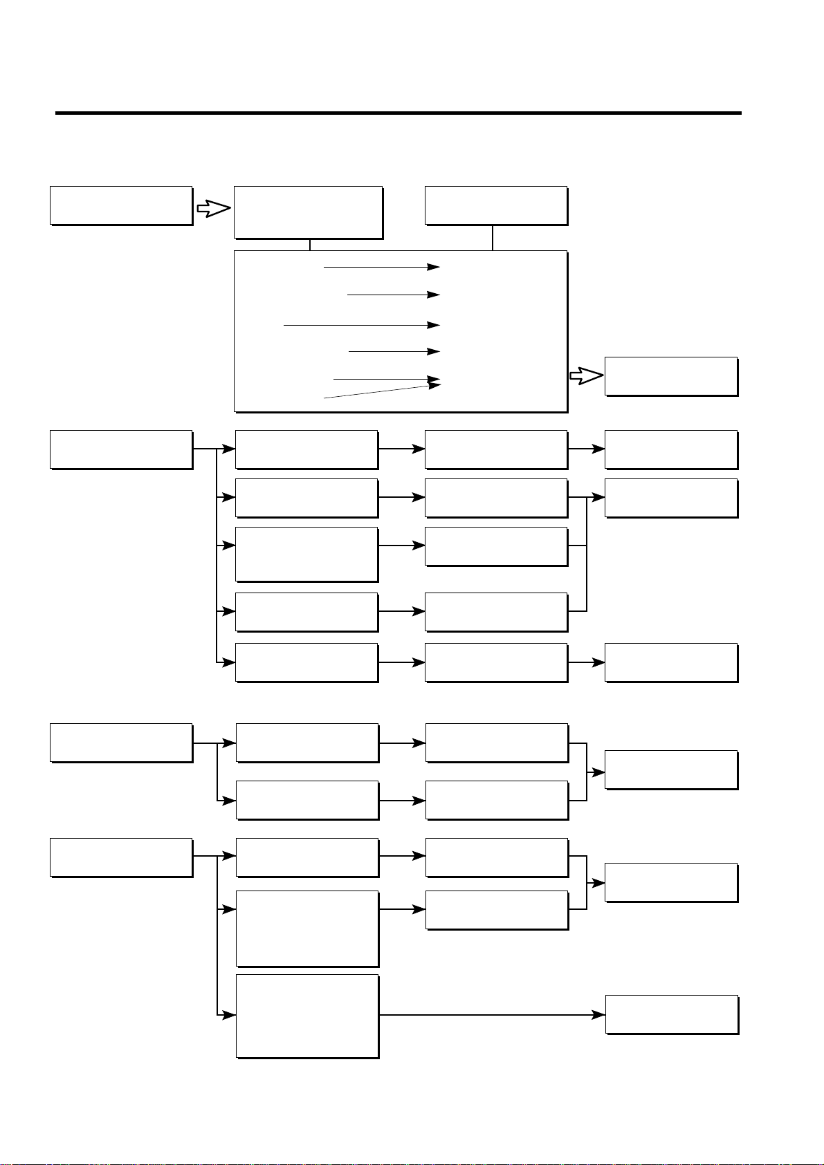
▼ Cooling is impossible
Compressor
doesn't run.
Compressor runs
poorly.
Check a starting
voltage.
Check if current flows to
the following
components.
a. Thermostat
b. Starting devices
c. OLP
d. Compressor coil
e. Defrost Timer
f. Circuit parts
Low voltage.
Poor contacting and
gas leakage.
Shorted or broken.
Poor contacting
or shorted.
Coil shorted.
Poor contacting
or shorted.
Poor contacting
and broken.
Shorted.
Lack of capacity.
Coil of motor
Compressor.
Replace
the compressor.
Replace
indicated component.
Raise the voltage.
Replace
indicated component.
Cause
Check if current flows
to starting devices.
Check current flowing
in sub-coil of
Compressor.
Check capacity of OLP.
The items described
above are normal.
▼ Cooling ability is poor
Fan motor
doesn't run.
Much frost is built upon
the EVAPORATOR.
Poor contacting.
Coil is shorted.
Shorted.
Replace
indicated component.
Replace
indicated component.
Replace
indicated component.
Running is poor.
(Coil is shorted.)
Check current flowing
of the door S/W.
Check current flowing
in the Fan Motor.
Check the running
condition of Timer.
Check current flowing
of the following
components.
• Defrost Thermostat
• Fuse-M
Check current flowing
of the following
components.
• L-cord
• TE-Plate Heater
6-4 OTHER ELECTRIC COMPONENTS
Page 13

6-4 SERVICE DIAGNOSIS CHART
- 13 -
COMPLAINT POINTS TO BE CHECKED REMEDY
Cooling is • Is the power cord unplugged from the outlet? • Plug to the outlet.
impossible. • Check if the power S/W is set to OFF. • Set the switch to ON.
• Check if the fuse of power S/W is shorted. • Replace fuse.
• Measure the voltage of power outlet. • If voltage is low, correct wiring.
Cooling ability • Check if the set is placed close to wall. • Place the set with the space of about 10 cm (4 inches).
is poor. • Check if the set is placed close to stove, gas • Place the set apart from these heat
• cooker and direct rays. • appliances.
• Is the ambient temperature high or • Make the ambient temperature below.
• the room door closed?
• Check if put in is hot. • Put in foods after cooled down.
• Did you open the door of the set too often • Don't open the door too often and close
• or check if the door is closed up? • it firmly.
• Check if the Control is set to WARM. • Set the control to mid-position.
Foods in the • Is food placed in cooling air outlet? • Place foods in high temperature section.
Refrigerator • (Front Part)
are frozen. • Check if the Dial is set to COLD. • Set the dial to MID.
• Is the ambient temperature below 5°C? • Set the dial to WARM.
Dew or ice • Is liquid food stored? • Seal up liquid foods with wrap.
forms inside • Check if put in hot. • Put in foods after cooled down.
the set. • Did you open the door of the set too • Don't open the door too often and close
• often or check if the door is closed. • it firmly.
Dew forms • Check if ambient temperature and humidity • Wipe dew with a dry cloth. This occurrence
in the Exterior Case. of surroumcling air are high. • is solved naturally in low temperature and humidity.
• Is there gap in the door gasket? • Fill up the gap.
Abnormal • Is the set positioned in a firm and even place? • Adjust the Adjust Screw, and position
noise. • in the firm place.
• Are any unnecessary objects set • Remove the objects.
• in the back side of the set?
• Check if the Drip Tray is not firmly fixed. • Fix it firmly on the original position.
• Check if the cover of mechanical room • Place the cover at the original position.
• in below and front side is taken out.
Door does not • Check if the door packing is dirty • Clean the door packing.
close well. • with filth such as juice.
• Is the set positioned in a firm and even place? • Position in the firm place and level the
• Adjust Screw.
• Is too much food putted in the set? • Keep foods not to reach the door.
Ice and foods • Check if the inside of the set is dirty. • Clean the inside of the set.
smell unpleasant. • Did you keep fragrant foods without wrapping? • Wrap fragrant foods.
• It smells of plastic. • The new products smells of plastic, but it
• will go away after 1-2 weeks.
● In addition to the items described left, refer to the followings to solve the complaint.
Check if dew forms in
the freezer.
Replace the
Components of
defrosting circuit.
Check Refrigerating
Cycle.
Check the
Thermistor
Defrosting
is poor.
The cycle
is faulty.
Repair the cycle.
Replace the
Thermistor.
The operation of
the Thermistor is
poor.
Page 14

6-5 REFRIGERATING CYCLE
- 14 -
▼ Troubleshooting Chart
▼ Leakage Detection
● Observe discharging point of refrigerant which may be in the oil discharging part in the compressor and hole of evaporator.
YES
YES
Check if compressor
runs or not.
Check if frost
forms or not in
Evaporator.
Observe the discharged
amount of Refrigerant.
Inject refrigerant to compressor
and check cooling operation.
Clogged by dust. Gas leakage.
Faulty
Compressor.
Moisture Clog
Check if oil
leaks or not.
Frost formed normally
Normal amount
No or much amount
(Check the leakage point)
Frost formed normally
No frost
or forms
in inlet only
Check Compressor
PARTIAL Freezer Low flowing sound of A little higher • Refrigerant level is low due
LEAKAGE compartment and Refrigerant is heard and than ambient • to a leak.
Refrigerator don't frost forms in inlet only temperature. • Normal cooling is possible
cool normally. • when injecting of Refrigerant
• the regular amount.
WHOLE Freezer Flowing sound of refrigerant Equal to ambient • No discharging of Refrigerant.
LEAKAGE compartment and is not heard and frost isn't temperature. • Normal cooling is possible
Refrigerator don't formed. • when injecting of Refrigerant
cool normally. • the regular amount.
PARTIAL Freeze Flowing sound of refrigerant A little higher • Normal discharging of
CLOG compartment and is heard and frost forms than ambient • refrigerant.
Refrigerator don't in inlet only. temperature. • The capillary tube is faulty.
cool normally.
WHOLE
Freezer
Flowing sound of refrigerant Equal to ambient • Normal discharging of
CLOG
compartment and
is not heard and frost isn't temperature. • Refrigerant.
Refrigerator don't cool.
formed.
MOISTURE Cooling operation Flowing sound of refrigerant Lower than • Cooling operation restarts
CLOG stops periodically. is not heard and frost melts. ambient • when heating the inlet of
temperature • capillary tube.
COMP- Freezer and Low flowing sound of A little higher • Low pressure at high side
RESSION Refrigerator refrigerant is heard and ambient • of compressor due to low
don't cool. frost forms in inlet only. temperature. • refrigerant level.
NO COMP- No compressing Flowing sound of refrigerant Equal to ambient • No pressure of high pressure
RESSION operation. is not heard and no frost. temperature. • part in the compressor.
CAUSE
TEMPERATURE
OF THE
COMPRESSOR
REMARKS
STATE OF
THE SET
STATE OF THE
EVAPORATOR
LEAKAGE
CLOGGED BY DUST
DEFECTIVE
COMPRESSION
Page 15

- 15 -
NO. ITEMS UNIT STANDARDS PURPOSES REMARKS
▼ General Control of Refrigerating Cycle
Pipe and
piping system
opening time
Welding
N
2 sealed
parts
Refrigeration
Cycle
Refrigerant
weighing
Drier
replacement
Leak check
1
2
3
4
5
6
7
Min.
Nitrogen
pressure
Confirm
N
2 leak
Min.
Torr
EA
EA
EA
EA
Pipe: within 1 hour.
Comp: within 10 minutes.
Drier: within 20 minutes.
Weld under Nitrogen
atmosphere.
(N
2 pressure:
0.1~0.2 kg/cm
2
)
Confirm air leaking sounds
when removing cap.
Sound: usable
No sound: not usable
More than 40 minutes
Below 0.03 (ref)
High and low pressure sides
are evacuated at the same
time for models above 200 l.
Use R-134a exclusive
manifold.
Use R-134a exclusive.
R-134a exclusive.
R-134a exclusive.
Use R-134a exclusively.
Weighing allowance: ±5g
Note: Winter: -5g
Summer: +5g
- Use R-134a exclusively for
R-134a refrigerator.
- Use R-12 exclusively for
R-12 refrigerator.
-
Replace drier whenever repairing
refrigerator cycle piping.
- Do not use soapy water for
check. It may be sucked
into the pipe by vacuum.
To protect
moisture
penetration.
To protect oxide
scale formation.
To protect
moisture
penetration.
To remove moisture.
To protect mixing
of mineral and
ester oils.
To protect R-12
refrigerant mixing.
"
"
Do not mix with
R-12 refrigerant.
To remove the
moisture from
pipe inside.
Defect
refrigerant leak
area.
The opening time should be reduced
to a half of the standards during rain
and rainy seasons (the penetration of
water into the pipe is dangerous).
- Refer to repair note in each part.
- R-134a refrigerant is more
susceptible to leaks than R-12 and
requires more care during welding.
-
Do not apply force to pipes before and
after welding to protect pipe from cracking.
- In case of evaporator parts, if it
doesn't make sound when removing
cap, blow dry air or N
2 gas for more
than 1 min and use the parts.
Note: Only applicable to the model
equipped with reverse flow
protect plate.
Vacuum efficiency can be improved
by operating compressor during
evacuation.
The bushing pipes for R-12 refrigerant
shall be melted when they are used for
R-134a refrigerant (causes of leak.)
- Do not weigh the refrigerant at too
hot or too cold an area.
(77°F[25°C] is adequate.)
-
Make Copper bombe (Device filling refrigerant)
Socket: 2SV Plug: 2PV R-134a
Note: Do not burn O-ring (bushing)
during welding.
- Check oil leak at refrigerant leak
area. Use electronic leak detector if
oil leak is not found.
- The electronic leak detector is very
sensitive to halogen gas in the air. It
also can detect R-141b in urethane.
Practice many times before using
this type of detector.
Evacuation
time
V acuum
degree
V acuum
V acuum
piping
Pipe
coupler
Outlet
(Socket)
Plug
Page 16

This manual describes function of models adhering Ice Maker.
7-1 OPERATION PRINCIPLE
7-1-1 Operation principle of Ice Maker
1. Turning the ice-making stop switch off stops ice-making function of the ice-maker and thus no ice is made .
2. Ice-making function stops at the time of selecting ice-making function and release of the ice-making function allows to
perform the initial control function again.
7.
OPERATION PRINCIPLE AND REPAIR METHOD OF ICE MAKER
- 16 -
•
Power Input
Initial Control
Icing Control
Ice-removing
Control
Water Supply
Control
Test Control
Keep a level of ice-removing tray with “initial control” inputting
power.
•
Wait until when water within ice-removing tray becomes cold
after starting ice-making operation.
•
Perform “ice-removing control” after supplying water to the iceremoving tray by operating solenoid of the ice valve.
•
As operation for the assembly line and service of refrigerator,
pressing a “I/Maker Test Switch” allows to operate in the order
of “initial ice-removing water supply” control step.
•
Perform “ice check operation” to ensure that ice is filled at an
ice bank by carrying out reverse turning and forward turning
the ice-removing motor. Perform “icing-removing operation for
dropping ices of ice-removing tray from the ice bank If ices
are not fully filled.
* Make sure the switch on the ice maker assy is turned “on”.
Page 17

7-2 Function of Ice maker
7-2-1 Initial control function
1. The level of the ice-removing tray (ice-removing container) after completing the MICOM initialization in the initial POWER
ON,returning to electricity failure and turning-off of ice-making stop switches. Namely, detection lever operates up and down.
2. The level of ice-removing container is detected with high / low output signal of hall sensor.
In another words, operation is performed in order to keep a level by operating ice-removing motor so that high or low voltage could be applied in the MICOM PIN.
3. No signal change of hall sensors until a minute after operating the ice-removing motor should be considered as failure. In
this case, stop the automatic ice-remover and then reset the ice-maker initialization if considered as normal after performing continuous check in a cycle of an hour.
4. Keeping of the ice-removing tray (ice-removing container) should be considered initial control is completed.
7-2-2 Water supply control function
1. Supply water into the ice-removing tray by operating the ice solenoid placed at the machine room of refrigerator using the
time check function if considered as the level is kept after performing a horizontal operation of the ice-making tray after
the ice-removing control (normal ice-removing control, ice-removing control of test function) is completed.
2. The quantity of water supply is determined by supplying water for a constant using the dip switch.
<Water Supply Quantity Table>
3. The change of the quantity of water supply setting may be done according to the changed time even after changing it
without powering off. In the change of dip switch during water supply, it is done according to the water supply time previously established and then done according to the additionally changed time from the next water supply.
7-2-3 Ice-making control function
1. Ice-making control is related with when considered as water within ice-making tray (ice container) turns into ice completely after completing water supply operation and performs ice-making completion operation by detecting temperature
of ice-making tray. (ice-making sensor is mounted on the bottom of the ice-making tray).
2. Ice-making control begins after completing water supply control or initial control.
3. It is considered that ice-making is completed if temperature of ice-making sensor arrives at -6°C after 60 minutes pass
from the time water is supplied to the ice-making tray.
4. It is considered that ice-making is completed if temperature of ice-making sensor arrives at below -7°C after 10 minutes
pass at the above status.
- 17 -
Remarks
The quantity of water supply may differ depending on
the setting status of the dip switch or on water pressure
as water supply method is of a pattern of direct connection to water cock.
* Make sure it is adjusted to meet the line indicating the
adequate amount of water supply.
Line indicating the
adequate amount
of water supply.
Adequate
water level.
Water supply control switch
* Adjust the water supply control switch to adjust the
amount of water being supplied.
SWITH
ON
SWITH
OFF
ON
SW1
123
SW2 SW3
SWITCH NO
SW1
SW2 SW3
OFF OFF OFF
ON OFF OFF
OFF ON OFF
ON ON OFF
OFF OFF ON
ON OFF ON
OFF ON ON
ON ON ON
TIME
10.5 sec
9 sec
10 sec
11 sec
12 sec
13 sec
14 sec
15 sec
Page 18

7-2-4 Ice-removing control function
1. Ice-removing control means operation to separate ice within ice-making tray ( ice-making container) after ice-making is
completed.
2. Step to check ices stored at the ice bank (container for storing ice) are fully filled. It is considered as they are fully filled if
signals of the hall sensor are at the On status (“high”) before 3.6seconds after rotating positively the ice-making motor. In
this case, the ice-making motor remains at the waiting status without performing ice-removing function.
Perform ice-detecting operation after rotating positively the ice-making motor in the cycle of an hour if the full ice status is
detected. Perform water supply control function after completing ice-removing function in the short of ices stored.
Reversely rotating the ice-removing motor in the storage of full ices and then let the motor stop at the position of the icemaking or waiting status.
3. Ice-removing control performs ice-removing operation immediately if ices stored at the ice bank (container for storing ice)
are not fully filled (the hall sensor are at the Off status (“low”) within 3.6seconds after rotating positively the ice-making
motor). In this case, it positively rotates (CW) the ice-removing motor and keeps the ice-making tray at the maximum distortion status and makes ices be separated from the ice-making tray. In this case, ice-detecting lever automatically operates lifting operation with ice-removing operation.
4. Ice-removing control positively rotates (CW) the ice-removing motor and stops it for a second as it considers as maximum
distortion point (ice-detecting axle = 160°) if the sensor signal changes from the Off status (“low”) to the On status (“high”)
after 3.6 seconds pass.
5. Ice-removing control positively rotates (CW) the ice-removing motor at the cycle of an hour if problems in ice-making
motor or hall sensor are found and performs initial operation or operates initialization of product if normal.
6. Ice-removing control stops for a second at the maximum distortion status of the ice-removing tray (container for storing
ice).
7. Step that the ice-removing tray stops for a second and then returns to the level. It returns to the level status returns to the
ice-removing tray by reversely rotating the ice-making motor.
8. The cycle of “water supply ➝ ice-making ➝ ice-removing ➝ returning to the level” if becoming the level status.
- 18 -
In the short of
ices stored
Output signal
of hall sensor
In full ices
stored
Output signal
of hall sensor
Operation of
ice-detecting axle
Ice-detection level 30°
Maximum distortion point
Ice-making
(original)
Lock
2±1 sec
9±3 sec
8±3 sec
Ice-detection Ice-removal lock
Lock
Level
status
Returning
to level
<Timing chart for ice-removal>
Page 19

7-2-5 Test Function
1. Function used compulsory operation for the purpose of performing operation test, service and cleaning. This test function
is performed if pressing the test switch mounted on the automatic ice-maker itself for 0.5 second or more.
2. The test button operates when the test function is not input but at the level status. It does not perform ice-removal control
and water supply control if ices are full during operation of test function
3. Pressing the test button for more than 0.5 seconds at the level the status immediately performs ice-removing operation
irrespective of the ice generation conditions of the ice-making tray.
Caution shall be exercised as water may overflow if operating the test function at the water status that ice-making is not
done. A cycle of water supply is performed at the level adjusting operation after ice-removing operation.
Therefore, the test button allows to check problems in ice-removing operation, level operation and water supply.
4. The test function operates in the normal cycle of ice-making ➝ ice-removal ➝ returning to the level ➝ water supply if
water supply is completed.
- 19 -
TEST S/W
* To check on the amount of water being supplied, press
the Test button. (Hold for 0.5 seconds)
Page 20

7-3 Failure diagnosis method of ice maker
- 20 -
No
Yes
No
No
Yes
Yes
DC power (5V,12V) is
normally output?
Defect of power terminal
• Check DC power (5V,12V)
Replacement of
MAIN PCB
Normally perform
ice-removing and returning to
the level if pressing TEST S/W
for more than 0.5
second?
Defect of ice-making sensor
Replacement of
ice-making sensor
Defect of ice-making kit
Replacement of
ice-making kit
Replacement of
MAIN PCB
Defect of ice-making KIT TEST S/W
Replacement of
ice-making kit
Replacement of
water supply valve
Defect of water supply
Water supply is
normal after the ice-making tray
and returning to the level with the
ice-removing motor?
Normal
• Check resistance values of
both ends of ice-making sensor
(Pin for PCB CON2 1,2 PIN)
• Ice-making sensor~Defect
between (PIN NO # 4 of IC1)
boards
• Both ends of TEST S/W
(# 3,6 pin of PCB CON2 3,6)
are at open status?
• TEST S/W ~ Defect between
boards (PIN NO #19 of IC1)
• Water supply valve conduct
current?
• Water supply pump normally
operates?
• Water supply line is normally
connected?
• Resistance values at both
ends of ice-removing motor
(# 7,8 pin of PCB CON2 7,8)
is 18°~22Ω ?
• Drive circuit of ice-removing
motor (IC5 and auxiliary
circuit) is normal?
• HALL IC~Defect between
(PIN NO # 20 of IC1) boards
• Be sure ice-removing and
returning to the level when
pressing the TEST S/W
Page 21

7-4 Explanation of ice maker circuits
7-4-1 Power circuit
The secondary party of transformer consists of power (12Vdc) for driving display and relay and power (5Vdc) supplying
power to MICOM and IC.
In this case, voltage at each part is as follows:
VA1 is parts for preventing over-voltage and noise and plays a role of protecting elements of the secondary part of transformer as the inside of element becomes short and is broken and power fuse is cut off when power of more than 175V is
applied.
7-4-2 Vibration circuit
Circuit used for synchronous clock generation for transmitting/receiving information of the inside logic elements of IC and
basic time generation for calculating time. Rated parts must be used as counting time is changed at the IC1 or the OSC1
does not operate if SPEC would be changed.
7-4-3 Reset circuit
The reset circuit is a circuit that initializes various parts such as RAM, etc inside of the MICOM (IC1) and starts the whole of
function from the initial status and ‘low’ voltage is applied for a constant time (10ms) at the reset terminal of the MICOM at
the start of power input.
The reset terminal is at 5V during general operation (the MICOM does not operate in the defect of the reset IC).
- 21 -
Part Both ends of VA1 Both ends of CE2 Both ends of CE3
Voltage 115Vac 12Vdc 5Vdc
Page 22

7-4-4 Load drive circuit
1. Load drive status check
- 22 -
Load Type Water Valve
Measurement Location A
Condition
ON 1V below
OFF 12V
Page 23

7-4-5 ICE MAKER drive/circuit
This circuit is a circuit used to embody functions such as ice-removing, full-ice detection, level noise, and ice-making temperature detection of ice-making tray (ice-making container).
- 23 -
Page 24

7-5 Main PWB Assembly and Parts List
7-5-1 MAIN PWB
- 24 -
Page 25

7-5-2 Replacement Part List
- 25 -
Page 26

7-6 PWB DIAGRAM
- 26 -
Page 27

- 27 -
Page 28

8. EXPLODED VIEW & REPLACEMENT PARTS LIST
- 28 -
▼ The parts of refrigerator and the shape of each part are subject to change in different localities.
▼ Capacitors and fuse are optional parts.
GR-T622, GR-T722
106A
104A
106A
401A
304A
103C
309A
318A
308A
314A
307A
312A
317A
310B
310A
103A
105A
301A
283B
282B
406B
103B
411A
328A
334B
323B
334A
315A
319A
329C
420A
319C
113D
113B
113C
410G
110A
410C
120B
409B
120C
158C
120A
145B
145A
282H
282E
282C
418A
281A
281B
Page 29

- 29 -
154A
151B
151C
151D
151A
147C*
147A*
151C
151D
170A
149A
330B
405C
404A
329A
405A
332A
110C
408A
409A
406A
158B
140D
140E
140B
140A*
141D
141E
141B
141A*
*
: Option
Page 30

- 30 -
241C
241A
241D
241C
241C
241B
205A
205A
243A
210A
233A
230A
203A
201A
231A
212A
244B
607A
607A
607A
244C
244B
1SZZ0A
244A
607A
244C
212G
1SZZ0A
281E
281E
211A
Handle Assembly,
Package
200A
Page 31

- 31 -
ICE MAKER PART
616E
623A
618A
616D
622A
620A
619A
605A
600A
603A
604A
5074AA
6923
601A
602A
603B
611A
Page 32

RUN-DATE: 02-07-26
BUYER NAME:LGEUS MODEL NAME:LRTBC1825T LG REFERENCE NO:GR-T622ATC.ATICLGX
COLOR:TITANIUM
- 32 -
S
AL
LOCA.NO
PART NO(LG) DESCRIPTION SPECIFICATION REMARK
6923 6923JB1001A MICOM ASSEMBLY
103A 3650JA2004U HANDLE,BACK
103B 3650JA2004V HANDLE,BACK
103C 3551JA2082D COVER ASSEMBLY,LOWER
104A 4441JA3001A CASTER ASSEMBLY
A 105A 5250JA2009A DRAIN,PIPE-Z
106A 4779JA2003B LEG ASSEMBLY,ADJUST
110A 6930JB1007C THERMOSTAT
110C 4940JD1007C KNOB,DAMPER
113B 4974JA2033A GUIDE,DUCT
113C 4970JA3016A SPRING,W
113D 4986JA2024A GASKET,DOOR
120A 4995JA1024K CONTROL BOX ASSEMBLY,R
120B 4994JD1037A CONTROL BOX,R
120C 4940JD1006E KNOB,DAMPER
140A 5027JA1041E SHELF ASSEMBLY,NET
140B 5027JA1029F SHELF ASSEMBLY,R
140D 5026JA2024E SHELF,NET
140E 5026JA2024F SHELF,NET
141A 5027JA1019Q SHELF ASSEMBLY,R
141B 5027JA1029F SHELF ASSEMBLY,R
141D 5026JA2020C SHELF,NET
141E 5026JA2020F SHELF,NET
145A 4930JA2032A HOLDER,SHELF
145B 4930JA2031A HOLDER,SHELF
149A 5026JA1108B SHELF ASSEMBLY,F
151A 3391JA1036G TRAY ASSEMBLY,VEGETABLE
151B 3391JA1036H TRAY ASSEMBLY,VEGETABLE
151C 4940JA2012A KNOB,DAMPER
151D 4940JA2011A KNOB,DAMPER
154A 3551JA1027D COVER ASSEMBLY,T/V
158B 4930JA1034A HOLDER,LAMP
158C 3550JA2096A COVER,LAMP
170A 3390JD1050G TRAY,MEAT
1SZZ0A 1TCG0403232
SCREW TAPPING,COUNTER SUNK HEAD
200A 3581JA1045Q DOOR ASSEMBLY,F
A 201A 5433JA0076F DOOR FOAM ASSEMBLY,F
203A 4987JA1024A GASKET ASSEMBLY,DOOR
205A 5004JD1110B BASKET,DOOR
210A 4620JA2011A STOPPER,DOOR
211A 3651JA2212A HANDLE ASSEMBLY,PACKAGE
212A 3650JA2053A HANDLE,F
Page 33

RUN-DATE: 02-07-26
BUYER NAME:LGEUS MODEL NAME:LRTBC1825T LG REFERENCE NO:GR-T622ATC.ATICLGX
COLOR:TITANIUM
- 33 -
S
AL
LOCA.NO
PART NO(LG) DESCRIPTION SPECIFICATION REMARK
212G 4140JD2001C NAME PLATE,P(H)
230A 3581JA8475C DOOR ASSEMBLY,R
A 231A 5433JA0077L DOOR FOAM ASSEMBLY,R
233A 4987JA1024B GASKET ASSEMBLY,DOOR
241A 5004JD1119A BASKET,DOOR
241B 5005JA1001B BASKET ASSEMBLY,DOOR
241C 5004JD1112B BASKET,DOOR
241D 5004JD1111B BASKET,DOOR
243A 4620JA3010B STOPPER,DOOR
244A 3650JA2054A HANDLE,R
244B 3650JA2055A HANDLE,DECO
244C 3650JA2056A HANDLE,DECO
281A 3550JA2132K COVER,HINGE
281B 4775JA2031B HINGE ASSEMBLY,U
281E 5006JA3054H CAP,HINGE
282B 4774JA2005A HINGE ASSEMBLY,C
282C 1WPZJA3007A WASHER,DRAWING
282E 5006JA2011U CAP,HINGE
282H 5006JA2020B CAP,HINGE
283B 4775JA2026A HINGE ASSEMBLY,L
301A 5421JA1032A EVAPORATOR ASSEMBLY
304A 3550JA1117A COVER,BACK-M/C
307A 2521C-B6282 COMPRESSOR,ASSEMBLY LA62LBCMC2 D DREF
A 308A 6748C-0004D P.T.C ASSEMBLY P6R8MD #250 MURATA
309A 6750C-0004M O.L.P 4TM414KFBYY-520
310A 3550JA2087A COVER,P.T.C
312A 5040JA3044A RUBBER,SEAT
314A 4620JA3009A STOPPER,COMP
315A 3103JA1015A COMP BASE ASSEMBLY,STD
317A 5851JA2003B DRIER
318A J719-00006A HOLDER,DRIER
319A 3390JA1115A TRAY,DRIP
319C 4974JA1046A GUIDE,FAN
323B 5403JA1026A CONDENSER ASSEMBLY,WIRE
327A 4J04328A RUBBER,DAMPING
328A 4J03020A RUBBER,DAMPING
329A J753-00011A FAN ASSEMBLY
329C 5901JA1005B FAN ASSEMBLY
330B 4998JA1010A SHROUD,F
332A 3531JA1018L GRILLE ASSEMBLY,FAN
334A 3550JA2095A COVER,PIPE
334B 5040JA3039A RUBBER,PIPE
Page 34

RUN-DATE: 02-07-26
BUYER NAME:LGEUS MODEL NAME:LRTBC1825T LG REFERENCE NO:GR-T622ATC.ATICLGX
COLOR:TITANIUM
- 34 -
S
AL
LOCA.NO
PART NO(LG) DESCRIPTION SPECIFICATION REMARK
401A 6615JB2003F CONTROLLER ASSEMBLY
404A 4681JB1011P MOTOR ASSEMBLY,REF FAN
405A 4810JA3007A BRACKET,MOTOR
A 405C J756-00008B RUBBER,MOTOR-N
406A 6600JB1005C SWITCH,[PUSH]
A 406B 6600JB1002K SWITCH,[PUSH]
408A 6621JB2005A SOCKET ASSEMBLY,LAMP
409A 6912JB2004F LAMP,[INCANDESCENT] 120V 25W
409B 6912JB2004C LAMP,[INCANDESCENT] 125V 40W
410C 6914JB2006G TIMER 120V
410G 0CBZJB2001E CAPACITOR,DRAWING 250VAC 12UF
411A 6411JB1013B POWER CORD ASSEMBLY
418A 5300JB1050R HEATER,SHEATH 115V 270W
420A 4681JB1013G MOTOR ASSEMBLY,REF FAN
5074AA 5074JA1023A BANK,ICE
600A 5989JA1004B ICE MAKER ASSEMBLY,KIT
601A 3390JA1118A TRAY,ICE
602A 4810JA1022A BRACKET,ICE MAKER
603A 3550JA3095A COVER,SENSOR
603B 5410JA3011A INSULATION,BACK
604A 4510JA3003A LEVER,ICE MAKER
605A 5988JA1001A ICE MAKER(MECH),UNIT
607A 4930JA3068A HOLDER,BRACKET
611A 3551JA2074A COVER ASSEMBLY,TRAY
616D 5210JA3005J TUBE,PE
616E 5210JA3021A TUBE,INJECT
618A 4810JA3036A BRACKET,COVER
619A 5220JA2009D VALVE,WATER
620A 1NZZJA3005A NUT,DRAWING
620A 1NZZJA3005A NUT,DRAWING
622A 5040JA3025A RUBBER,INJECT
623A 4770JA3001A BAND (MECH)
Page 35

RUN-DATE: 02-07-26
BUYER NAME:LGEUS MODEL NAME:LRTBC2025T LG REFERENCE NO:GR-T722ATC.ATICLGX
COLOR:TITANIUM
- 35 -
S
AL
LOCA.NO
PART NO(LG) DESCRIPTION SPECIFICATION REMARK
6923 6923JB1001A MICOM ASSEMBLY
103A 3650JA2004U HANDLE,BACK
103B 3650JA2004V HANDLE,BACK
103C 3551JA2082D COVER ASSEMBLY,LOWER
104A 4441JA3001A CASTER ASSEMBLY
A 105A 5250JA2009A DRAIN,PIPE-Z
106A 4779JA2003B LEG ASSEMBLY,ADJUST
110A 6930JB1007C THERMOSTAT
110C 4940JD1007C KNOB,DAMPER
113B 4974JA2033A GUIDE,DUCT
113C 4970JA3016A SPRING,W
113D 4986JA2024A GASKET,DOOR
120A 4995JA1022H CONTROL BOX ASSEMBLY,R
120B 4994JD1037B CONTROL BOX,R
120C 4940JD1006E KNOB,DAMPER
140A 5027JA1041J SHELF ASSEMBLY,NET
140B 5027JA1030E SHELF ASSEMBLY,R
140D 5026JA2016E SHELF,NET
140E 5026JA2016F SHELF,NET
141A 5027JA1019U SHELF ASSEMBLY,R
141B 5027JA1030E SHELF ASSEMBLY,R
141D 5026JA2012C SHELF,NET
141E 5026JA2012F SHELF,NET
145A 4930JA2032A HOLDER,SHELF
145B 4930JA2031A HOLDER,SHELF
147A 5074JA1008A TRAY,EGG
147C 3550JA1077A COVER,BANK
149A 5026JA1108A SHELF ASSEMBLY,F
151A 3391JA1036G TRAY ASSEMBLY,VEGETABLE
151B 3391JA1036H TRAY ASSEMBLY,VEGETABLE
151C 4940JA2012A KNOB,DAMPER
151D 4940JA2011A KNOB,DAMPER
154A 3551JA1027D COVER ASSEMBLY,T/V
158B 4930JA1034A HOLDER,LAMP
158C 3550JA2096A COVER,LAMP
170A 3390JD1050H TRAY,MEAT
1SZZ0A 1TCG0403232
SCREW TAPPING,COUNTER SUNK HEAD
200A 3581JA1045Q DOOR ASSEMBLY,F
A 201A 5433JA0076F DOOR FOAM ASSEMBLY,F
203A 4987JA1024A GASKET ASSEMBLY,DOOR
205A 5004JD1110B BASKET,DOOR
210A 4620JA2011A STOPPER,DOOR
Page 36

RUN-DATE: 02-07-26
BUYER NAME:LGEUS MODEL NAME:LRTBC2025T LG REFERENCE NO:GR-T722ATC.ATICLGX
COLOR:TITANIUM
- 36 -
S
AL
LOCA.NO
PART NO(LG) DESCRIPTION SPECIFICATION REMARK
211A 3651JA2212A HANDLE ASSEMBLY,PACKAGE
212A 3650JA2053A HANDLE,F
212G 4140JD2001C NAME PLATE,P(H)
230A 3581JA8475C DOOR ASSEMBLY,R
A 231A 5433JA0077L DOOR FOAM ASSEMBLY,R
233A 4987JA1024B GASKET ASSEMBLY,DOOR
241A 5004JD1119A BASKET,DOOR
241B 5005JA1001B BASKET ASSEMBLY,DOOR
241C 5004JD1112B BASKET,DOOR
241D 5004JD1111C BASKET,DOOR
243A 4620JA3010B STOPPER,DOOR
244A 3650JA2054A HANDLE,R
244B 3650JA2055A HANDLE,DECO
244C 3650JA2056A HANDLE,DECO
281A 3550JA2132K COVER,HINGE
281B 4775JA2031B HINGE ASSEMBLY,U
281E 5006JA3054H CAP,HINGE
282B 4774JA2005A HINGE ASSEMBLY,C
282C 1WPZJA3007A WASHER,DRAWING
282E 5006JA2011U CAP,HINGE
282H 5006JA2020B CAP,HINGE
283B 4775JA2026A HINGE ASSEMBLY,L
301A 5421JA1032A EVAPORATOR ASSEMBLY
304A 3550JA1117A COVER,BACK-M/C
307A 2521JA1006C COMPRESSOR,ASSEMBLY
308A 6748JA3001A P.T.C
309A 6750JA3001A O.L.P
310A 3550JA2158A COVER,P.T.C
310B 4620JA3014A STOPPER,CORD
312A 5040JA3044A BUSHING,SEAT
314A 4620JA3009A STOPPER,COMP
315A 3103JA1015B COMP BASE ASSEMBLY,STD
317A 5851JA2003B DRIER
318A J719-00006A HOLDER,DRIER
319A 3390JA1115A TRAY,DRIP
319C 4974JA1046A GUIDE,FAN
323B 5403JA1026A CONDENSER ASSEMBLY,WIRE
328A 4J03020A BUSHING,DAMPING
329A J753-00011A FAN ASSEMBLY
329C 5901JA1005B FAN ASSEMBLY
330B 4998JA1010A SHROUD,F
332A 3531JA1018L GRILLE ASSEMBLY,FAN
Page 37

RUN-DATE: 02-07-26
BUYER NAME:LGEUS MODEL NAME:LRTBC2025T LG REFERENCE NO:GR-T722ATC.ATICLGX
COLOR:TITANIUM
- 37 -
S
AL
LOCA.NO
PART NO(LG) DESCRIPTION SPECIFICATION REMARK
334A 3550JA2095A COVER,PIPE
334B 5040JA3039A BUSHING,PIPE
401A 6615JB2003F CONTROLLER ASSEMBLY
404A 4681JB1011P MOTOR ASSEMBLY,REF FAN
405A 4810JA3007A BRACKET,MOTOR
A 405C J756-00008B BUSHING,MOTOR-N
406A 6600JB1005C SWITCH,[PUSH]
A 406B 6600JB1002K SWITCH,[PUSH]
408A 6621JB2005A SOCKET ASSEMBLY,LAMP
409A 6912JB2004F LAMP,[INCANDESCENT] 120V 25W
409B 6912JB2004C LAMP,[INCANDESCENT] 125V 40W
410C 6914JB2006G TIMER 120V
410G 0CBZJB2001E CAPACITOR,DRAWING 250VAC 12UF
411A 6411JB1013B POWER CORD ASSEMBLY
418A 5300JB1050R HEATER,SHEATH 115V 270W
420A 4680JB1029A MOTOR ASSEMBLY,REF FAN 115V/60HZ
5074AA 5074JA1023A BANK,ICE
600A 5989JA1004B ICE MAKER ASSEMBLY,KIT
601A 3390JA1118A TRAY,ICE
602A 4810JA1022A BRACKET,ICE MAKER
603A 3550JA3095A COVER,SENSOR
603B 5410JA3011A INSULATION,BACK
604A 4510JA3003A LEVER,ICE MAKER
605A 5988JA1001A ICE MAKER(MECH),UNIT
607A 4930JA3068A HOLDER,BRACKET
611A 3551JA2074A COVER ASSEMBLY,TRAY
616D 5210JA3005J TUBE,PE
616E 5210JA3021A TUBE,INJECT
618A 4810JA3036A BRACKET,COVER
619A 5220JA2009D VALVE,WATER
620A 1NZZJA3005A NUT,DRAWING
620A 1NZZJA3005A NUT,DRAWING
622A 5040JA3025A BUSHING,INJECT
623A 4770JA3001A BAND (MECH)
Page 38

P/No. 3828JD8332Y JUL., 2002 Printed in Korea
 Loading...