

LG LRTBC1825xx Service Manual
CAUTION
BEFORE SERVICING THE UNIT,
READ THE SAFETY PRECAUTIONS IN THIS MANUAL.
REFRIGERATOR
SERVICE MANUAL
http://biz.lgservice.com
MODEL : LRTBC1825T
LRTBC2025T
COLOR: TITANIUM

SAFETY PRECAUTIONS....................................................................................................................................................... 2
SERVICING PRECAUTIONS.................................................................................................................................................. 3
SPECIFICATIONS................................................................................................................................................................... 4
PARTS IDENTIFICATION....................................................................................................................................................... 5
DISASSEMBLY.................................................................................................................................................................... 6-7
DOOR................................................................................................................................................................................... 6
DOOR SWITCH.................................................................................................................................................................... 6
THERMOSTAT..................................................................................................................................................................... 6
FAN AND FAN MOTOR........................................................................................................................................................ 7
DEFROST CONTROL ASSEMBLY...................................................................................................................................... 7
LAMP.................................................................................................................................................................................... 7
CONTROL BOX-R................................................................................................................................................................ 7
ADJUSTMENT........................................................................................................................................................................ 8
COMPRESSOR.................................................................................................................................................................... 8
POSITIVE TEMPERATURE COEFFICIENT-STARTER....................................................................................................... 8
OVERLOAD PROTECTOR.................................................................................................................................................. 9
CIRCUIT DIAGRAM................................................................................................................................................................ 9
TROUBLESHOOTING..................................................................................................................................................... 10-15
COMPRESSOR AND ELECTRIC COMPONENTS ........................................................................................................... 10
POSITIVE TEMPERATURE COEFFICIENT AND OVERLOAD PROTECTOR................................................................. 11
DEFROST TIMER .............................................................................................................................................................. 11
OTHER ELECTRIC COMPONENTS ................................................................................................................................. 12
SERVICE DIAGNOSIS CHART.......................................................................................................................................... 13
REFRIGERATING CYCLE............................................................................................................................................ 14-15
OPERATION PRINCIPLE AND REPAIR METHOD OF ICE MAKER ............................................................................ 16-27
EXPLODED VIEW .......................................................................................................................................................... 28-31
REPLACEMENT PARTS LIST............................................................................................................................................ 32-
CONTENTS
- 2 -
Please read the following instructions before servicing your
refrigerator.
1. Check the refrigerator for current leakage.
2. To prevent electric shock, unplug before servicing.
3. Always check line voltage and amperage.
4. If you use any kind of appliance, check regular current,
voltage, and capacity.
5. Don't touch metal products in the freezer with wet
hands. This may cause frostbite.
6. Prevent water from following onto electric elements in
the mechanical parts.
7. Close the top door before opening the bottom door.
Otherwise, you might hit your head when you stand up.
8. When tilting the refrigerator, remove any materials on
the refrigerator, especially the thin plates (ex. Glass
shelf or books.)
9. When servicing the evaporator, wear cotton gloves.
This is to prevent injuries from the sharp evaporator
fins.
10. Leave the disassembly of the refrigerating cycle to a
specialized service center. The gas inside the circuit
may pollute the environment.
SAFETY PRECAUTIONS
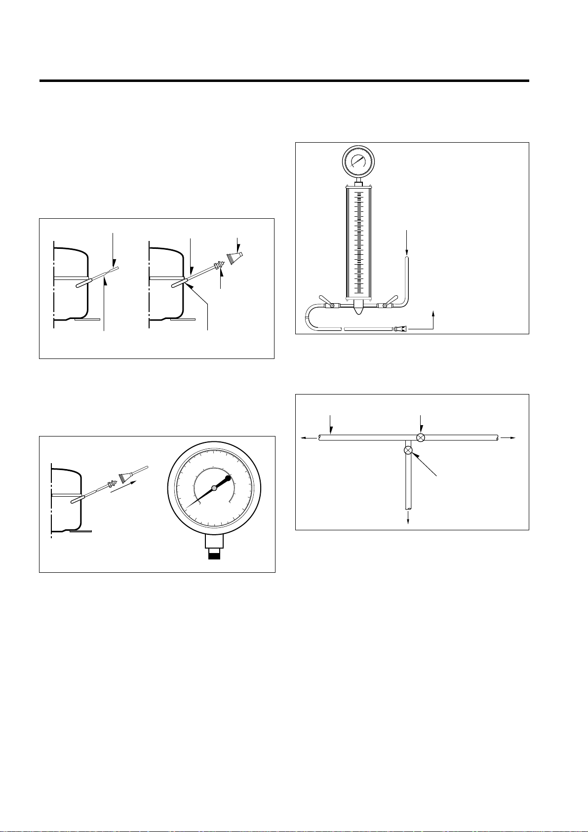
AIR RECHARGING IN COMPRESSOR
Test the refrigeration system connecting it electrically before
refilling operation. It is necessary to ascertain the function
of the motor-compressor and identify the defects
immediately. If defects have been found, empty the old
system of possible R-134a residue by breaking off the end
of the extension piece at its narrow point. (Figure 1)
Replace the filter and any damaged components. Unsolder
and pull off the piece remaining inside the service tube and
then attach an complete extension with male Hansen and
at last, solder it to the same tube again. (Figure 2)
It is necessary to execute the soldering operation with
valve open so that the fumes caused by oil residue can
come out freely without blowholes between two tubes
during the heating the of the point to be soldered.
The extension fitted with the male Hansen is connected to
the female fitting of the vacuum pump tube. (Figure 3)
Air evacuating from the system begins as soon as the
pump starts. The refrigeration system must be kept under
vacuum until the reading on the low-pressure gauge
indicates vacuum (0 absolute, -1 atm., -760 mm hg). In any
case it is advisable to keep the pump running for about 30
minutes. (Figure 3)
If considerable leakage occurs, it will be necessary to stop
the vacuum pump and to add a small quantity of Freon to
the system. If vacuum should not be obtained (pressure
gauge can't fall to 1 atmosphere), start the refrigeration
unit and find the leakage with special leak-finder. When the
defective soldering point is visible, repair it after opening
the extension tube valve and reestablishing the normal
outside pressure inside the group.
Because the melted alloy is sucked into the tubes and
blocks them, the pressure must be rebalanced when
vacuum is in the system when soldering. As soon as the
vacuum operation is over, add the quantity in grams of
R-134a to the refrigeration system. Remember that every
system has an exact quantity of R-134a that can be added
with a tolerance of ±5 grams. (Figure 4)
Before performing this operation (if the vacuum pump and
refilling cylinder are connected), make sure that the valve
placed between the vacuum pump and the refilling tube is
closed in order to keep the Freon for addition to the system.
(Figure 5)
In addition, check the graduated scale on the cylinder for
the quantity of R-134a to be added, for example, if we
have 750 grams of Freon in the cylinder and must add 140
grams to the group, this amount will be reached when
R-134a has dropped to 610 grams, remembering that the
indicator shows a lower limit of meniscus. Do this after
choosing the scale corresponding to the gas pressure
different scales reported as the same gas pressure
indicated by the pressure gauge on the top of the column.
To make R-134a flow into the system, open the valve
placed at the base of the cylinder connected to the filling
tube. The amount of Freon cannot be added to the system
all at once because it may cause a blocking of motorcompressor. Therefore, proceed by adding the original
quantity of about 20-30 grams and close the valve
immediately.
The pressure rises and the motor compressor must start
sucking the gas and lowering the pressure again. Open the
valve again, maintaining the same manner until reaching to
the quantity of R-134a established for the system being
charged. When the system is running, the suction pressure
must be stabilized between 0.30 to 0.6 (0.10 to 0.4)
atmosphere.
SERVICING PRECAUTIONS
- 3 -
POINT TO BE BROKEN
SERVICE TUBE EXTENSION
CHARGE TUBE
EXTENSION
FEMALE
HANSEN
MALE HANSEN
SOLDERING POINT
Figure 1 Figure 2
TO THE
VACUUM
PUMP
PRESSURE
GAUGE
Figure 3
TO THE R-134a CYLINDER
TO THE REFRIGERATION
SYSTEM
Figure 4
FILLING OR
CHARGE TUBE
VALVE TO BE OPENED
WHEN REFILLING
VALVE TO BE CLOSED
AFTER VACUUM
TO THE CHARGE
CYLINDER
TO THE REFRIGERATION
SYSTEM
TO THE
VACUUM
PUMP
Figure 5
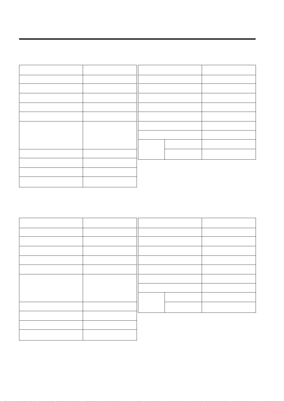
1. SPECIFICATIONS
- 4 -
ITEMS SPECIFICATIONS
DOOR DESIGN All Rounded
DIMENSIONS (mm)
754.5 X 735 X 1732 (W X D X H
)
NET WEIGHT (kg) 90
COOLING SYSTEM Fan Cooling
TEMPERATURE CONTROL Knob Dial
Full Automatic
DEFROSTING SYSTEM Heater Defrost
With a Timer
DOOR FINISH Vinyl Coated Metal
HANDLE TYPE Bar
INNER CASE ABS Resin
INSULATION Polyurethane Foam
ITEMS SPECIFICATIONS
VEGETABLE TRAY Transparent Drawer Type
COMPRESSOR PTC Starting Type
EVAPORATOR Fin Tube Type
CONDENSER Wire Condenser
REFRIGERANT R-134a (155 g)
LUBRICATING OIL ISO10 (280 cc)
DEFROSTING DEVICE SHEATH HEATER
FREEZER 25 W
LAMP
REFRIGERATOR 40 W
1. Ref. No.: LRTBC1825T
ITEMS SPECIFICATIONS
DOOR DESIGN All Rounded
DIMENSIONS (mm)
754.5 X 788 X 1732 (W X D X H
)
NET WEIGHT (kg) 93
COOLING SYSTEM Fan Cooling
TEMPERATURE CONTROL Knob Dial
Full Automatic
DEFROSTING SYSTEM Heater Defrost
With a Timer
DOOR FINISH Vinyl Coated Metal
HANDLE TYPE Bar
INNER CASE ABS Resin
INSULATION Polyurethane Foam
ITEMS SPECIFICATIONS
VEGETABLE TRAY Transparent Drawer Type
COMPRESSOR PTC Starting Type
EVAPORATOR Fin Tube Type
CONDENSER Wire Condenser
REFRIGERANT R-134a (155 g)
LUBRICATING OIL ISO10 (280 cc)
DEFROSTING DEVICE SHEATH HEATER
FREEZER 25 W
LAMP
REFRIGERATOR 40 W
2. Ref. No.: LRTBC2025T
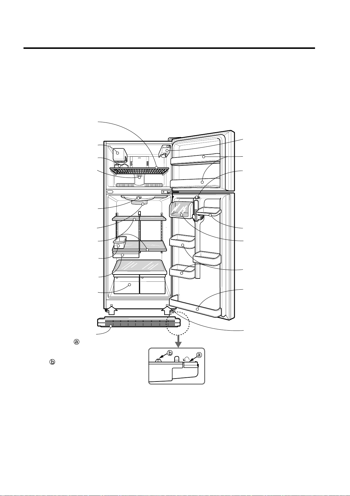
2. PARTS IDENTIFICATION
- 5 -
Automatic Ice Maker
Ice Cube Box
FREEZER
COMPARTMENT
REFRIGERATOR
COMPARTMENT
Freezer Temperature
Control Dial
Freezer Shelf
Door Cooling
On the refrigerator door,
the cold air passageway is
installed to supply
cold air to the doorside of
the refrigerator
compartment.
Temperature
Control Dial
Lamp
Shelves
Egg Box
(option)
Snack Corner
Crisper
Used to keep fruits
and vegetables
fresh and crisp.
Freezer Door Bin
Lamp
Refrigerator Door
Rack
Can Server
Adjustable
Door Bin
Leveling Screw
(Inside)
Dairy Corner
Base Grille
1. Bend down.
2. Push the grille toward the
refrigerator.
3. <Three protecting
parts> should be beneath
the bottom plate while
pushing the grille.
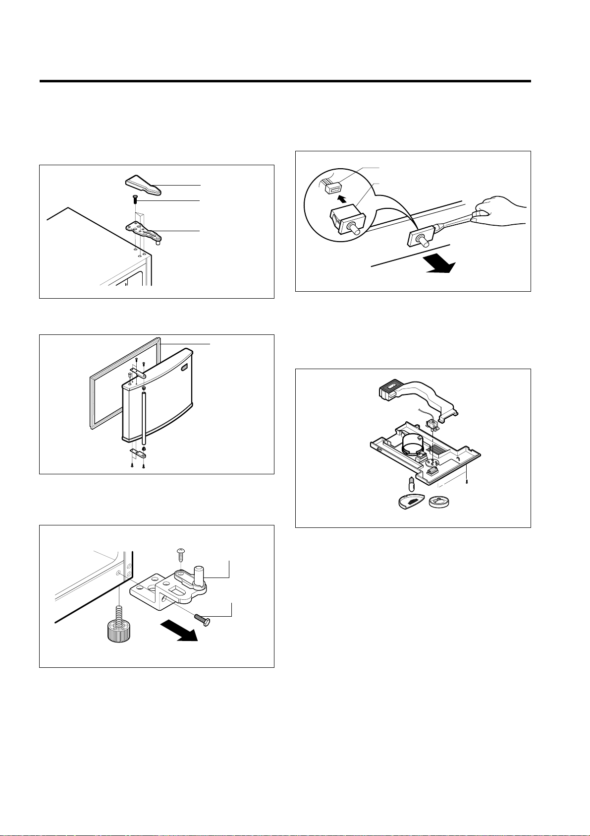
3-1 DOOR
● Freezer Door
1. Remove the hinge cover by pulling it upwards.
2. Loosen hexagonal bolts fixing the upper hinge to the
body and lift the freezer door.
3. Pull out the door gasket to remove from the door foam
assembly.
● Refrigerator Door
1. Loosen hexagonal bolts attaching the lower hinge to the
body to remove the refrigerator door only.
2. Pull out the door gasket to remove from the door foam
assembly.
3-2 DOOR SWITCH
1. To remove the door switch, pull out it with a slotted type
driver as shown in (figure 9).
2. Disconnect the lead wire from the switch.
3-3 THERMOSTAT
1. Remove Control Box-R by loosening 2 screws attached to
ceiling of Refrigerator compartment (Figure 10)
2. Separate the thermostat and dial knob F.
3. Remove the thermostat by disconnecting the lead wire.
3. DISASSEMBLY
- 6 -
BOLT
HINGE
HINGE COVER
Figure 6
GASKET
Figure 7
LOWER HINGE
BOLT
Figure 8
DOOR SWITCH
LEAD WIRE
Figure 9
Figure 10
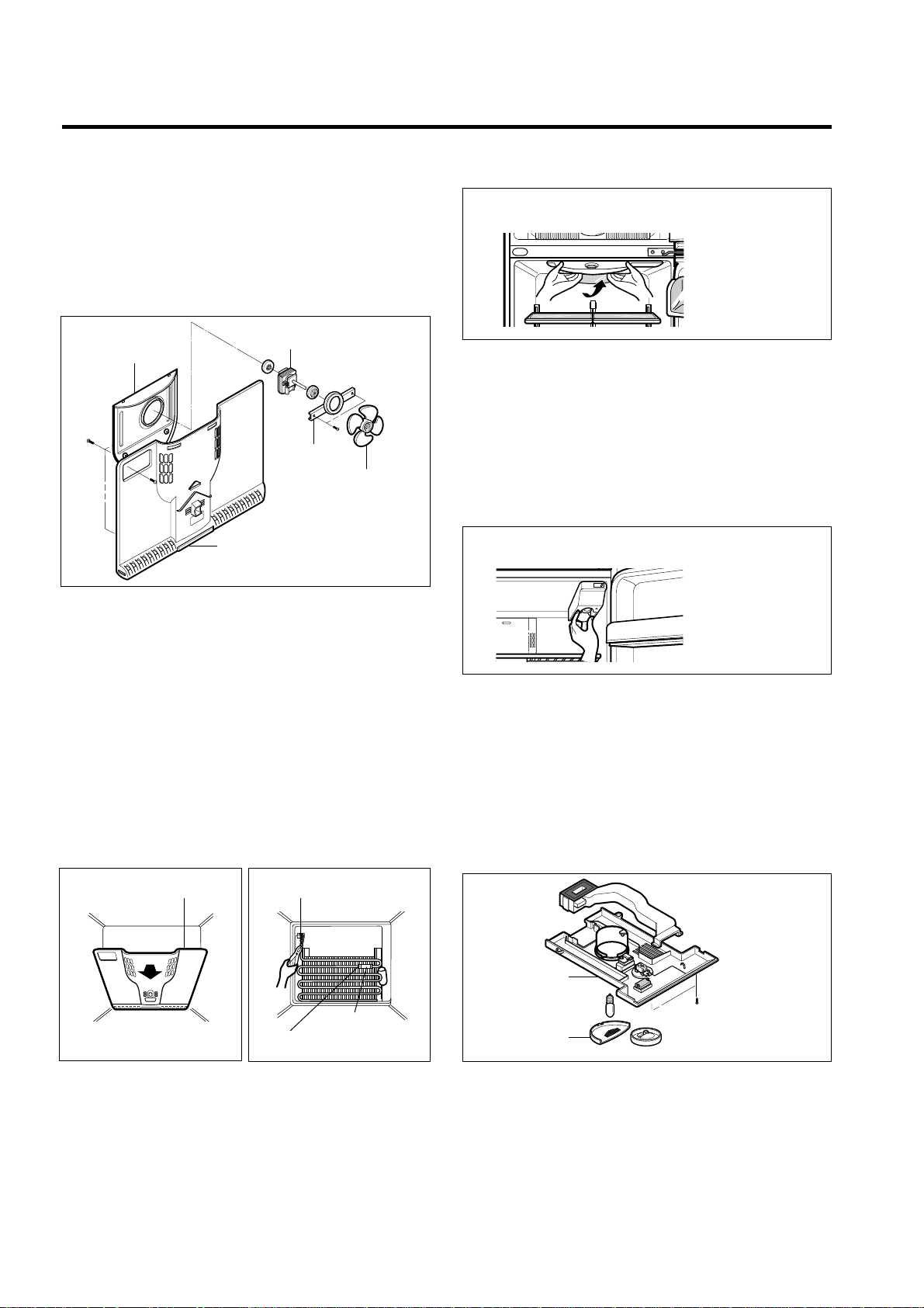
3-4 FAN AND FAN MOTOR
1. Remove the freezer shelf. (If your refrigerator have an
Ice Maker, disassemble the Ice maker first)
2. Remove the grille by pulling it out and by loosening a
screw.
3. Remove the Fan Motor assembly by loosening 4 screws
and disassemble the shroud.
4. Pull out the fan and separate the Fan Motor and Bracket.
3-5 DEFROST CONTROL ASSEMBLY
Defrost control assembly consists of Defrost Thermostat
and FUSE–M.
Defrost Thermostat functions to defrost automatically and it
is attached to metal side of the Evaporator and senses
Temp.
Fuse-M is a safety device for preventing over-heating of
the Heater when defrosting.
At the temperature of 77°C, it stops the emission of heat
from the Heater.
1. Pull out the grille assembly.
2. Separate the connector connected with the Defrost
Control assembly and replace the Defrost Control
assembly after cutting the Tie Wrap. (Figure 14)
3-6 LAMP
3-6-1 Refrigerator room lamp
1. Unplug the power cord from the outlet.
2. Remove refrigerator shelves.
3. Release the hooks on both ends of the lamp shield and
pull the shield downward to remove it.
4. Turn the lamp counterclockwise.
5. Assemble in reverse order of disassembly. Replacement
bulb must be the same specification as original.
(Max 40 W)
3-6-2 Freezer room lamp
1. Unplug refrigerator or disconnect power.
2. Reach behind light shield to remove bulb.
3. Replace bulb with a 25-watt appliance bulb.
4. Plug in refrigerator or reconnect power.
3-7 CONTROL BOX-R
1. First, remove all shelves in the refrigerator and Control
Box-R by loosening 2 screws.
2. Remove the Control Box-R by pulling it downward.
3. Disconnect the lead wire on the right position and
seperate timer, themostat, Lamp socket, etc.
- 7 -
FAN
BRACKET
SHROUD
GRILLE
FAN MOTOR
Figure 12
SHROUD-F
Figure 13
DEF-THERMO
FUSE-M
HOLDER FUSE
Figure 14
REFRIGERATOR ROOM LAMP
Figure 16-1
Figure 16-2
CONTROL BOX
COVER LAMP
Figure 17
FREEZER ROOM LAMP
4-1 COMPRESSOR
4-1-1 Role
The compressor intakes low temperature and low pressure
gas evaporated from evaporator of the refrigerator, and
condenses this gas to high temperature and high pressure
gas, and then plays delivering role to condenser.
4-1-2 Composition
The compressor includes overload protection. The PTC
starter and OLP (overload protector) are outside the
compressor. Since the compressor is manufactured to
tolerances of 1 micron, and is sealed in a dust - and
moisture - free environment, use extreme caution when
repairing it.
4-1-3 Note for Usage
(1) Be careful not to allow over-voltage and over-current.
(2) No Strike
If applying forcible power or strike (dropping or careless
handling), poor operation and noise may occur.
(3) Use proper electric components appropriate to the
Compressor.
(4) Note to Keep Compressor.
If Compressor gets wet in the rain and rust in the pin of
Hermetic Terminal, the result may be poor operation
and poor contact may cause.
(5) Be careful that dust, humidity, and welding flux don't
contaminate the compressor inside when replacing the
Compressor. Dust, humidity, and flux due to welding
which contaminates the cylinder may cause lockage
and noise.
4-2 PTC-STARTER
4-2-1 Composition of PTC-Starter
(1) PTC (Positive Temperature Coefficient) is a no-contact
semiconductor starting device which uses ceramic
material consisting of BaTiO
3.
(2) The higher the temperature is, the higher the resistance
value. These features are used as starting device for
the Motor.
4-2-2 Role of PTC-Starter
(1) PTC is attached to Hermetic Compressor used for
Refrigerator, Show Case, and starting Motor.
(2) Compressor for household refrigerator applies to
single-phase induction Motor.
For normal operation of the single-phase induction
motor, in the starting operation flows in both main coil
and sub-coil. After the starting is over, the current in
subcoil is cut off. The proper features of PTC play all
the above roles. So, PTC is used as a motor starting
device.
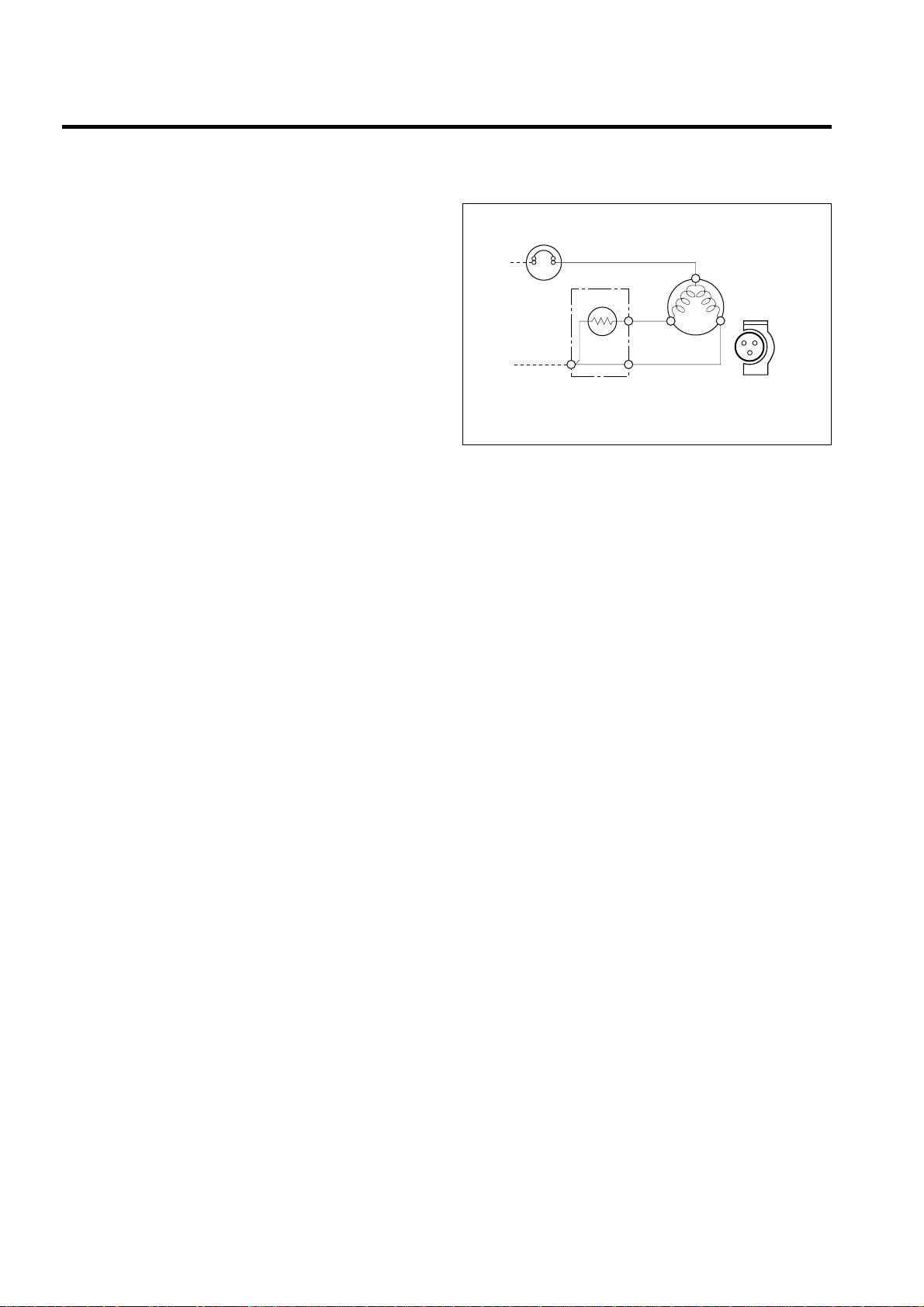
4-2-3 PTC-Applied Circuit Diagram
● According to Starting Method for the Motor
4-2-4 Motor Restarting and PTC Cooling
(1) For restarting after power off during normal
Compressor Motor operation, plug the power cord after
5 min. for pressure balance of Refrigerating Cycle and
PTC cooling.
(2) During normal operation of the Compressor Motor, PTC
elements generate heat continuously. Therefore,
if PTC isn't cooled for a while after the power has been
shut off, the motor will not restart.
4-2-5 Relation of PTC-Starter and OLP
(1) If the power is off during operation of Compressor and
the power is on before the PTC is cooled, (instant shutoff within 2 min. or unplugging and reconnecting), the
PTC isn't cooled and a resistance value grows. As a
result, current can't flow to the sub-coil, the Motor can't
operate, and the OLP operates by flowing over current
in only in the main-coil.
(2) While the OLP repeats on and off operation about 3-5
times, PTC is cooled and Compressor Motor performs
normal operation.
If OLP doesn't operate when PTC is not cooled,
Compressor Motor is worn away and causes circuitshort and fire. Therefore, always use a properly
attached OLP.
4-2-6 Note to Use PTC-Starter
(1) Be careful not to allow over-voltage and over-current.
(2) Do not strike
Don't apply a forcible power or strike.
(3) Keep apart from any liquid.
If liquid, such as oil or water away enters the PTC,
PTC materials may fail due to insulation breakdown of
the material itself.
(4) Don't change PTC at your convenience.
Don't disassemble PTC and case. If the exterior to the
PTC-starter is damaged, resistance value is altered and
it may cause poor starting of the compressor motor
may cause.
(5) Use a properly attached PTC.
4. ADJUSTMENT
- 8 -
PTC STARTER
HERMETIC
TERMINAL
COMPRESSOR
MOTOR
C
M
S
M
3
6
5
S
PTC
OVERLOAD PROTECTOR(O.L.P)
RSIR
Figure 19
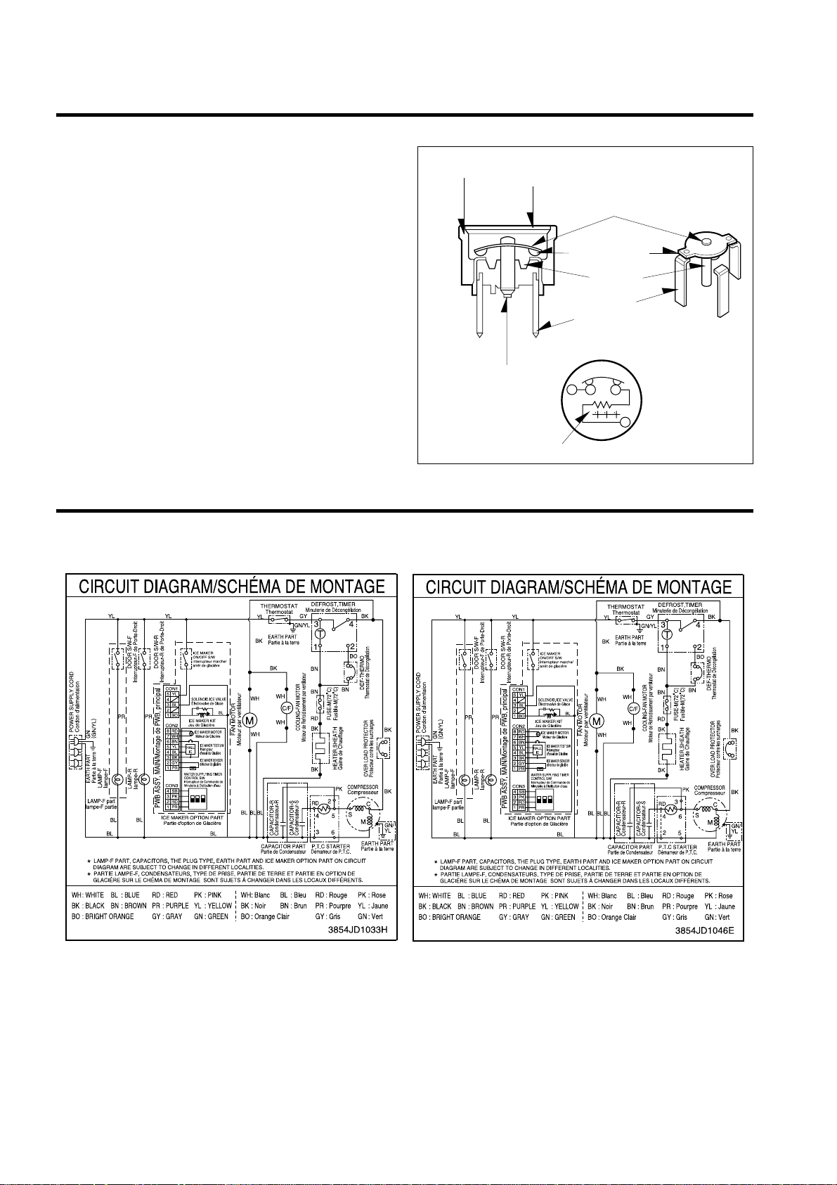
4-3 OLP (OVERLOAD PROTECTOR)
4-3-1 Definition of OLP
(1) OLP (OVERLOAD PROTECTOR) is attached to the
Compressor and protects the Motor by cutting the
current to the Motor if the temperature rises and
activates the bimetal spring in the OLP.
(2) When over-voltage flows to Compressor motor, the
Bimetal works by heating the heater inside the OLP,
and the OLP protects Motor by cutting off current which
flows to the Compressor Motor.
4-3-2 Role of the OLP
(1) The OLP is attached to the Hermetic Compressor used
for the Refrigerator and prevents the Motor Coil from
being started in the Compressor.
(2) Do not turn the Adjust Screw of the OLP in any way for
normal operation of the OLP.
(Composition and connection diagram of OLP)
- 9 -
5. CIRCUIT DIAGRAM
CONTACTING
POINT
COVER
BIMETAL
CONTACTING
POINT
HEATER
TERMINALS
ADJUST
SCREW
HEATER
BIMETAL
Figure 21
Ref. No.: LRTBC1825T Ref. No.: LRTBC2025T
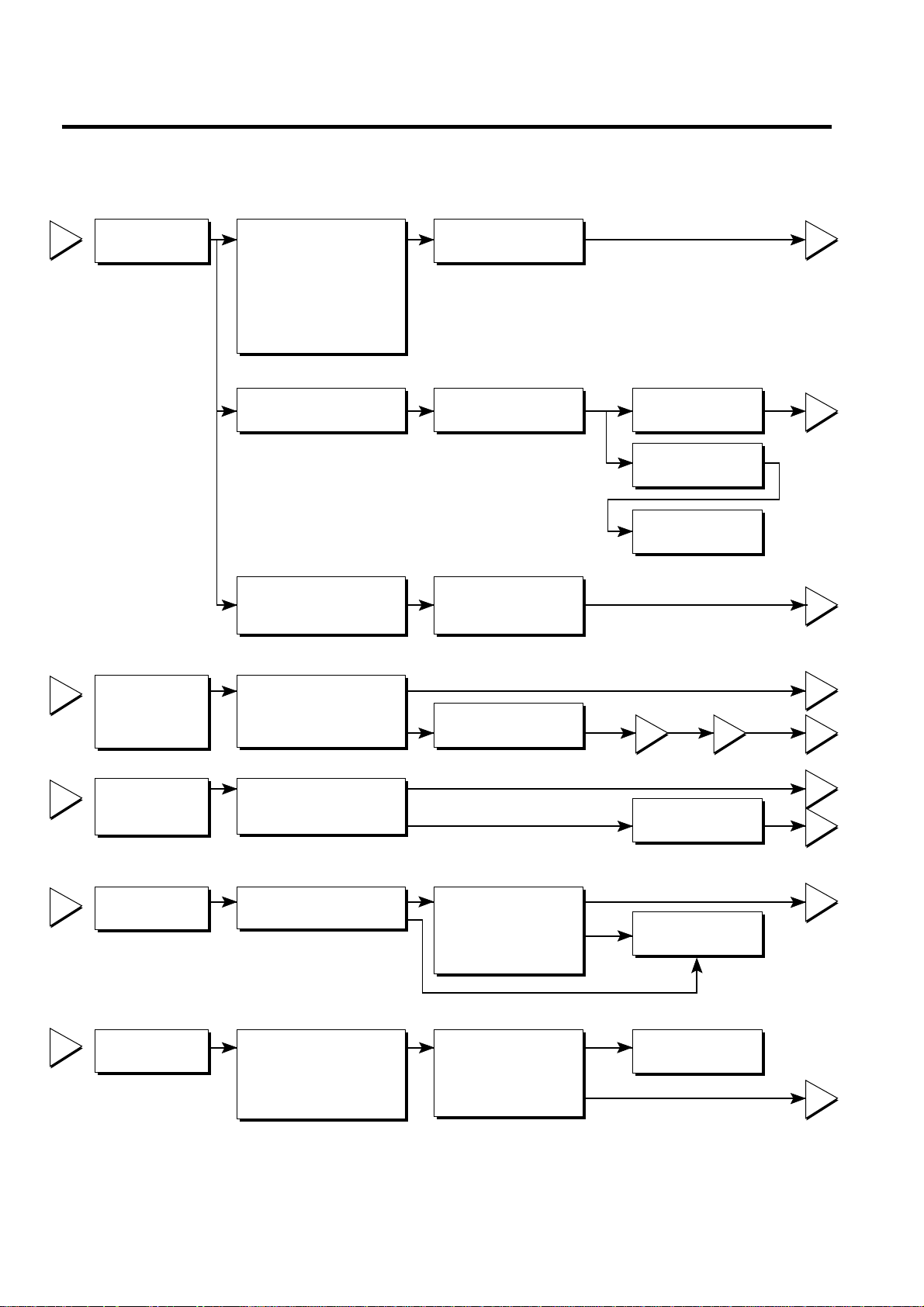
6. TROUBLESHOOTING
- 10 -
6-1 COMPRESSOR AND ELECTRIC COMPONENTS
1
2
3
4
5
2
5
5
3
5
4
5
5
1
43
YES
YES
YES
YES
NO
NO
YES
YES
YES
NO
NO
NO
Power Source.
No Voltage.
(Rating Voltage
±10%)?
Replace OLP.
Reconnect.
Replace
PTC-Starter.
Replace OLP.
O.K.
Check connection
condition.
OLP disconnected?
Advise the customer
to use a regular
transformer.
Replace Compressor.
OLP works within
30 sec. in forcible OLP
operation by turning
instant power on and
off.
Components start in
the voltage of Rating
Voltage ±10%
below.
Applied voltage isn't
in the range of Rating
Voltage ±10%.
Remove the PTCStarter from the
Compressor and
measure the voltage
between Terminal C of
Compressor and
Terminals 5 or 6 of PTC.
Check the resistance
among M-C, S-C and
M-S in Motor
Compressor.
Check the resistance
of two terminals in
PTC-Starter.
Check if applying
a regular OLP.
Measure minimum
starting voltage after 5
min. for balancing cycle
pressure and cooling the
PTC.
Check the
resistance of
Motor
Compressor.
Check the
resistance of
PTC-Starter.
Check OLP.
Check
starting state.
- 11 -
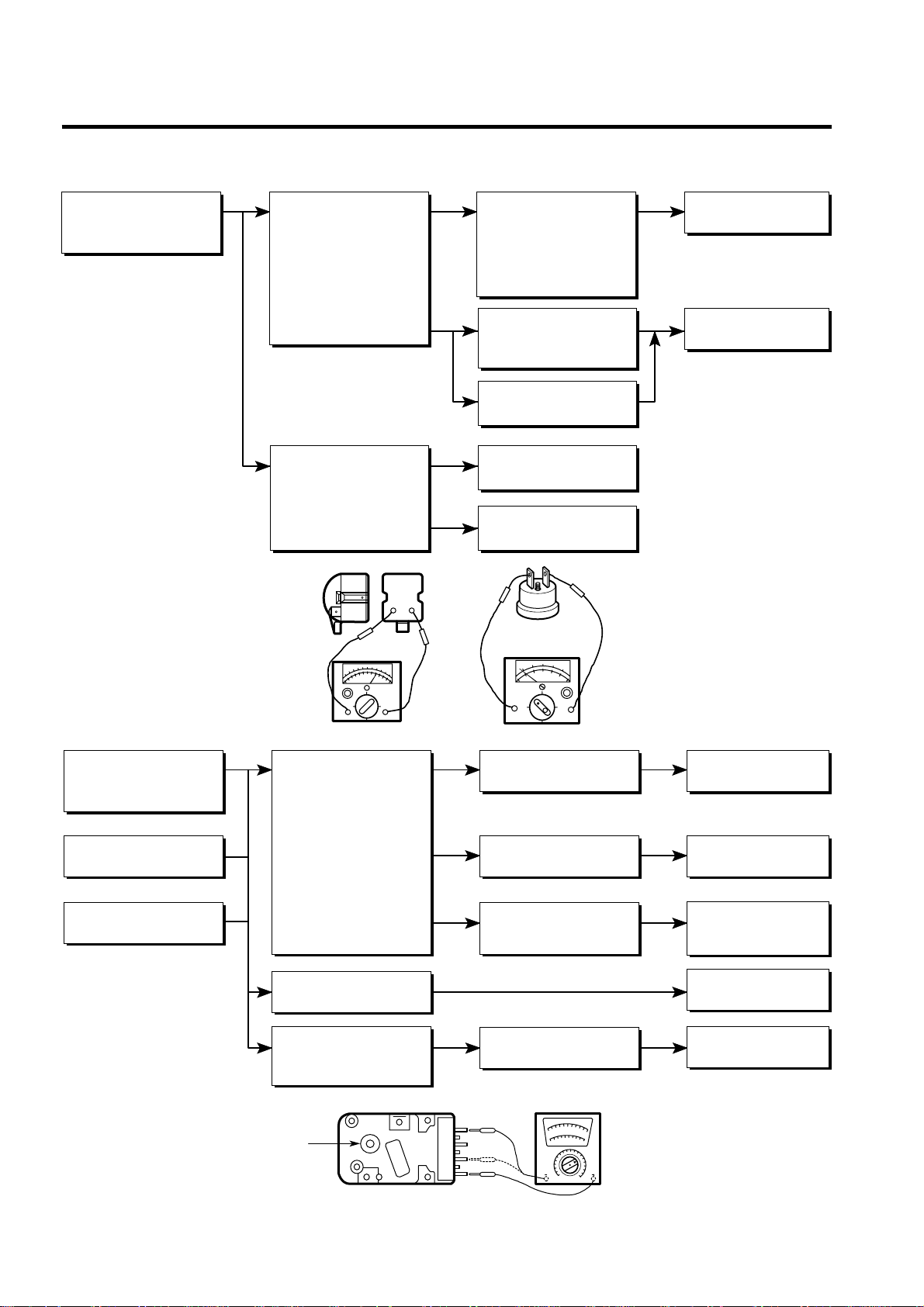
6-2 PTC AND OLP
65
YES
NO
NO
YES
NO
Cam Shaft
Normal operation of
Compressor is
impossible or poor.
Separate the PTCStarter from
Compressor and
measure the
resistance between
No. 5 and 6 of PTCStarter with a Tester or
Wheatstone Bridge.
(Figure 21)
Separate the OLP from
Compressor and check
the resistance value
between two terminals
of OLP with a Tester.
(Figure 22)
Observation value is
220V/50Hz : 22Ω±30%
115V/60Hz : 6.8Ω±30%
240V/50Hz : 33Ω±30%
127, 220V/60Hz : 22Ω
±30%
The resistance value
is 0 or several
hundred Ω.
The value is ∞.
Check another
electric components.
Replace OLP.
Check another
electric components.
Replace PTCStarter
Figure 21
Figure 22
Figure 23
Normal operation of
the Defrost Timer is
impossible.
No defrosting.
Poor cooling.
Position the Cam Shaft to
the point of first click
sound and check the
current flowing between
terminals No. 1(brown)
and No. 2(bright orange).
Next, position the Cam
Shaft to the point of
second click sound and
check the current flowing
between terminals
No. 1 (brown) and
No. 4 (black)
(Figure 23).
Turn the Cam Shaft.
Shake about 3 times
with holding the Cam
Shaft and Body softly.
The resistance is ∞.
The resistance is
0Ω or variable.
The resistance is about
220V/50Hz : 20KΩ
115V/60Hz : 7.8KΩ
Loud click sound.
Replace the
Defrost Timer.
Replace the
Defrost Timer.
Replace the
Defrost Timer.
Check the another
electric components.
Replace the
Defrost Timer.
6-3 DEFROST TIMER
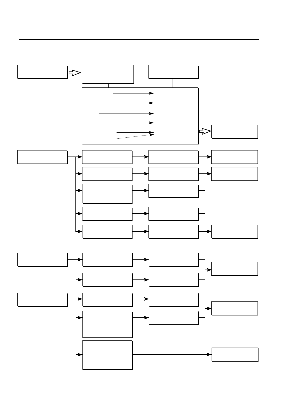
- 12 -
▼ Cooling is impossible
Compressor
doesn't run.
Compressor runs
poorly.
Check a starting
voltage.
Check if current flows to
the following
components.
a. Thermostat
b. Starting devices
c. OLP
d. Compressor coil
e. Defrost Timer
f. Circuit parts
Low voltage.
Poor contacting and
gas leakage.
Shorted or broken.
Poor contacting
or shorted.
Coil shorted.
Poor contacting
or shorted.
Poor contacting
and broken.
Shorted.
Lack of capacity.
Coil of motor
Compressor.
Replace
the compressor.
Replace
indicated component.
Raise the voltage.
Replace
indicated component.
Cause
Check if current flows
to starting devices.
Check current flowing
in sub-coil of
Compressor.
Check capacity of OLP.
The items described
above are normal.
▼ Cooling ability is poor
Fan motor
doesn't run.
Much frost is built upon
the EVAPORATOR.
Poor contacting.
Coil is shorted.
Shorted.
Replace
indicated component.
Replace
indicated component.
Replace
indicated component.
Running is poor.
(Coil is shorted.)
Check current flowing
of the door S/W.
Check current flowing
in the Fan Motor.
Check the running
condition of Timer.
Check current flowing
of the following
components.
• Defrost Thermostat
• Fuse-M
Check current flowing
of the following
components.
• L-cord
• TE-Plate Heater
6-4 OTHER ELECTRIC COMPONENTS
 Loading...