

LG LRTBC1825T Owner’s Manual
SERVICING PRECAUTIONS
AIR RECHARGING IN COMPRESSOR
Test the refrigeration system connecting it electrically before
refilling operation. It is necessary to ascertain the function
of the motor-compressor and identify the defects
immediately. If defects have been found, empty the old
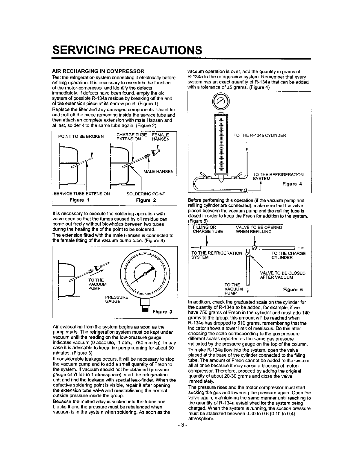
system of possible R-134a residue by breaking off the end
of the extension piece at its narrow point. (Figure 1)
Replace the filter and any damaged components. Unsolder
and pull off the piece remaining inside the service tube and
then attach an complete extension with male Hansen and
at last, solder it to the same tube again. (Figure 2)
POINT TO BE BROKEN CHARGE TUBE FEMALE
SERVICE TUBE EXTENSION SOLDERING POINT
Figure 1 Figure 2
It is necessary to execute the soldering operation with
valve open so that the fumes caused by oil residue can
come out freely without blowholes between two tubes
during the heating the of the point to be soldered.
The extension fittedwith the male Hansen is connected to
the female fitting of the vacuum pump tube. (Figure 3)
EXTENSION HANSEN
i MALE NANSEN
vacuum operation is over, add the quantity in grams of
R-134a to the refrigeration system. Remember that every
system has an exact quantity of R-134a that can be added
with a tolerance of ±5 grams. (Figure 4)
TO THE R-134a CYLINDER
TOsYsTEMTHEREFRIGE TION
f Figure4
Before performing this operation (if the vacuum pump and
refilling cylinder are connected), make sure that the valve
placed between the vacuum pump and the refilling tube is
closed in order to keep the Fraon for addition to the system.
(Figure 5)
FILUNG OR VALVE TO BE OPENED
CHARGE TUBE WHEN REFILLING
GAUGE
Figure 3
Air evacuating from the system begins as soon as the
pump starts. The refdgerafion system must be kept under
vacuum until the reading on the fow-pressure gauge
indicates vacuum (0 absolute, -1 atm., -760 mm hg). In any
case it is advisable to keep the pump running for about 30
minutes. (Figure 3)
If considerable leakage occurs, it will be necessary to stop
the vacuum pump and to add a small quantity of Freon to
the system, ffvacuum should not be obtained (pressure
gauge can't fall to 1 atmosphere), start the refrigeration
unit and find the leakage with special leak-finder. When the
defective soldering point is visible, repair it after opening
the extension tube valve and reestablishing the normal
outside pressure inside the group.
Because the melted alloy is sucked into the tubes and
blocks them, the pressure must be rebalancad when
vacuum is in the system when soldering. As soon as the
TO THE REFRIGERATION TO THE CHARGE
SYSTEM CYLINDER
VALVE TO BE CLOSED
AFTER VACUUM
TO THE
VACUUM I Figure 5
PUMP
In addition, check the graduated scale on the cylinder for
the quantity of R-134a to be added, for example, if we
have 750 grams of Freon in the cylinder and must add 140
grams to the group, this amount will be reached when
R-134a has dropped to 610 grams, remembering that the
indicator shows a lower limit of meniscus. Do this after
choosing the scale corresponding to the gas pressure
different scales reported as the same gas pressure
indicated by the pressure gauge on the top ofthe column.
To make R-134a flow into the system, open the valve
placed at the base of the cylinder connected to the filling
tube. The amount of Freon cannot be added to the system
all at once because it may cause a blocking of motor-
compressor. Therefore, proceed by adding the original
quantity of about 20-30 grams and close the valve
immediately.
The pressure rises and the motor compressor must start
sucking the gas and lowering the pressure again. Open the
valve again, maintaining the same manner until reaching to
the quantity of R-134a established for the system being
charged. When the system is running, the suction pressure
must be stabilized between 0.30 to 0.6 (0.10 to 0.4)
atmosphere.
-3-

2000.12. 6 160/120
CIRCUITDIAGRAM/SCHeMADEMONTAGE
. Jt _|
C,kPi,CIIORpARTp,T.DSTi_Ti_R PINiliIi QI_
* IJ_Mp-FpART,CJkp/,c;II_a.S,THEpLUGTYPE,F.AFm4pN_'AND ICE_ OPTIONpARTONC;RCUn"
DIAGRAMARE SUBJECTTOCHi_I_ IN DIFFEREN'rLOCALmF_
* pi_I"IE LAMP_-F.CONDENSATI_U_,"Pt_ 10EpRI_, pARTIEDETI_E ET PARI1EEN (3PTJONDE
OCJ*CII_EBUffLEC;1_ _ MONTAeEI_r _t,lEr$/_ _R D/_'8 tJ_ LOCAUX_.
WH:_iTE BL :BLUE RD:RED PK:PiNK : WH _ BL:Bleu RD:Rooge PK:Ro_
81(:BLI,CK BN:BROW_ PR:PLI_FLEYL:YELLOW: BK:Ncb BN:B_m PR:POa_We Yl.:Jaune
_O:B_]IGITTO_AJqGE GY:GRAY GN:GREBq : BO:Onm_eCl_ GY:_m GN:V_
Plde_eCm_m_ _ p:r_
i
_ pART
WA_R _A_PL¥1NG'riMECON_OL
OP'iION
1_._,¢co_,,,,,,,.,=,,,
_. CAUllON: Ptme mplooth_po*_ coed
AVB_ISSEMB_'T:Ve_llezd6brancharIs
cordm_'drnenle_ deb primrnum_.
TIME
Temp_
10.5 S_
9sec
10 se_
11se_
12se(
13se_
14se(
15se_
_ =--3 r"3
6WITCH0N
SW1 SW2 SW3
3854JD1033H
2. PARTS IDENTIFICATION
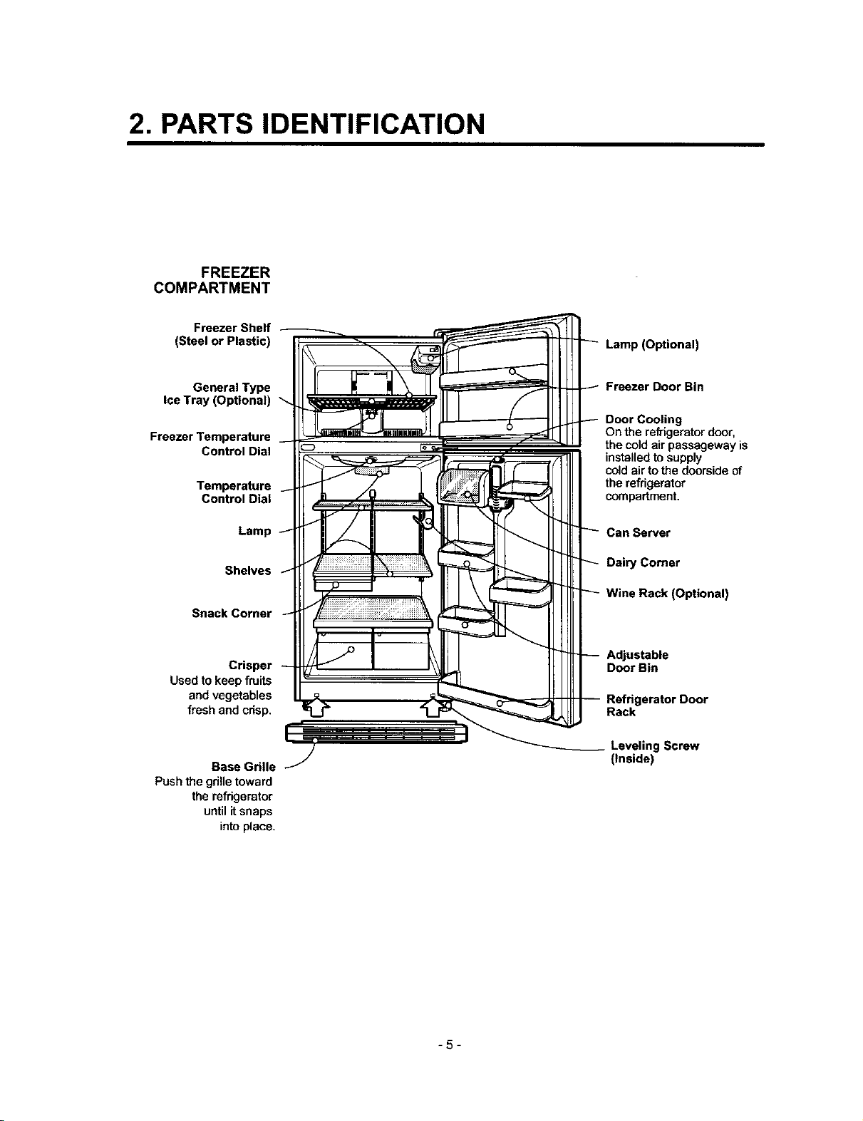
FREEZER
COMPARTMENT
Freezer Shelf
(Steel or Plastic)
Lamp (Optional)
General Type
ice Tray (Optional)
Freezer Temperature
Control Dial
Temperature
Control Dial
Lamp
Shelves
Snack Comer
Crisper
Used tokeep fruits
and vegetables
fresh and crisp.
Base Grille
Pushthe grilletoward
the refrigerator
untilitsnaps
intoplace.
Freezer Door Bin
Door Cooling
On the refrigerator door,
the cold air passageway is
installedto supply
coldair to the doorsideof
the refrigerator
compartment.
Can Server
Dairy Comer
Wine Rack (Optional)
Adjustable
Door Bin
Refdgerator Door
Rack
g Screw
(inside)
-5-
3. DISASSEMBLY
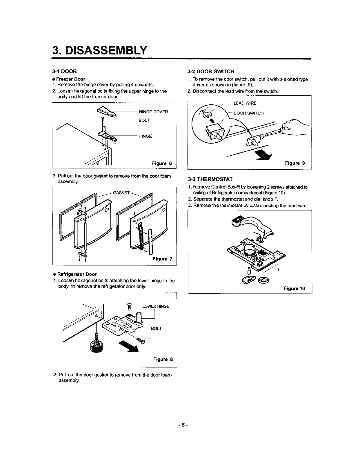
3-1 DOOR
• Freezer Door
1. Remove the hinge cover by pulling it upwards.
2. Loosen hexagonal boltsfixing the upper hinge to the
body and liftthe freezer door,
HINGE COVER
HINGE
BOLT
Figure 6
3. Pull out the door gasket to remove from the door foam
assembly,
3-2 DOOR SWITCH
1. To remove the door switch, pull out it with a slotted type
driver as shown in (figure 9).
2. Disconnect the lead wire from the switch.
LEAD WIRE
DOOR SWITCH
Figure 9
3-3 THERMOSTAT
1. Remove Control Box-R by loosening 2 screws attached to
ceilingof Refrigerator compartment (Figure 10)
2. Separate the thermostat and dial knob F.
3. Remove the thermostat by disconnecting the lead wire.
Figure 7
• Refrigerator Door
1. Loosen hexagonal bolts attaching the lower hinge tothe
body to remove the refrigerator door only.
LOWERHINGE
Figure 8
2. Pullout the doorgasket to removefromthe door foam
assembly.
Figure 10
-6-
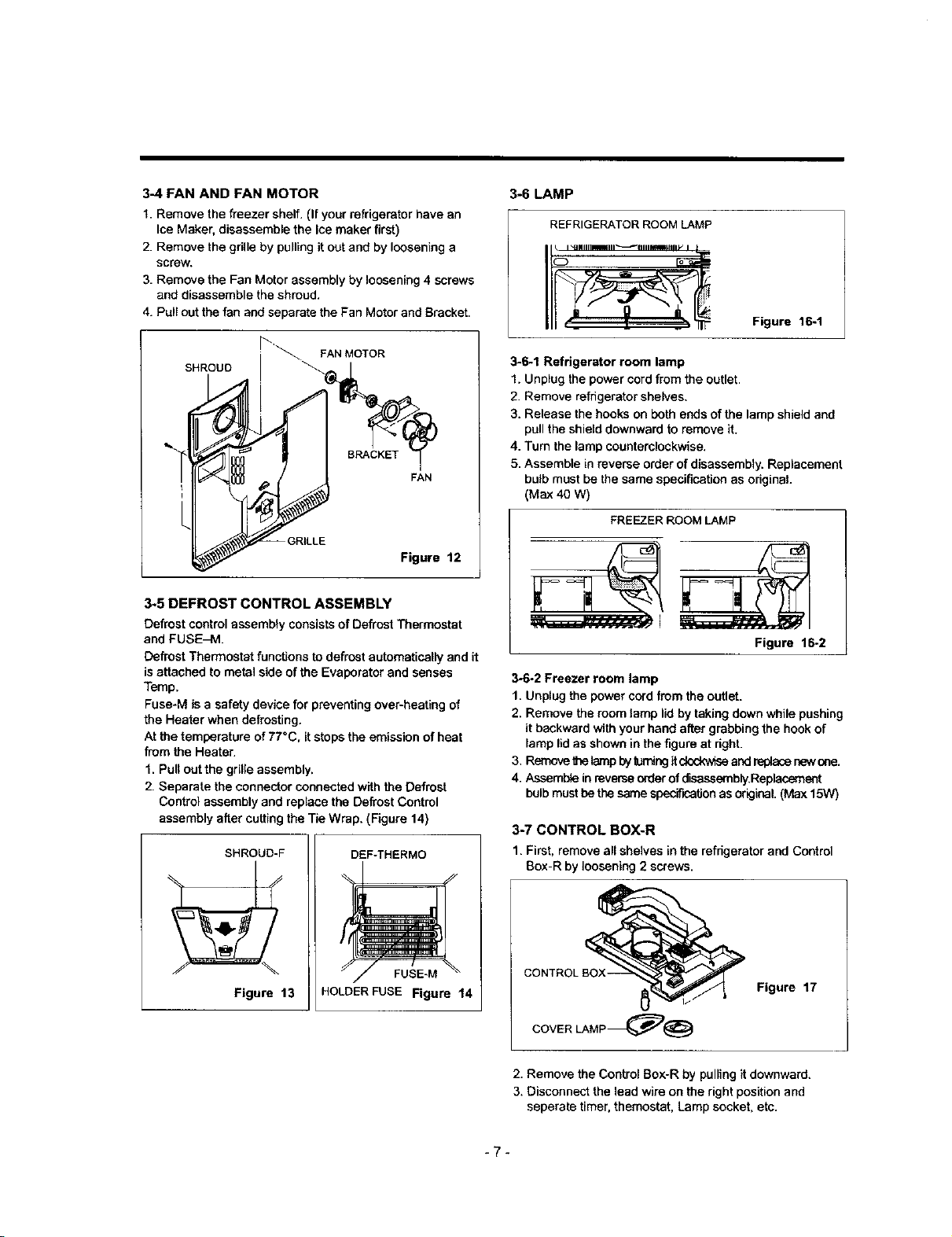
3-4 FAN AND FAN MOTOR
1. Remove the freezer shelf. (If your refrigerator have an
Ice Maker, disassemble the Ice maker first)
2. Remove the gdlle by pulling it out and by loosening a
screw.
3. Remove the Fan Motor assembly by loosening 4 screws
and disassemble the shroud.
4. Pull out the fan and separate the Fan Motor end Bracket.
3-6 LAMP
REFRIGERATOR ROOM LAMP
Figure 16-1
SHROUD
Figure 12
3-5 DEFROST CONTROL ASSEMBLY
Defrost control assembly consists of Defrost Thermostat
and FUSE_M.
Defrost Thermostat functions to defrost automatically and it
is attached to metal side of the Evaporator and senses
Temp.
Fuse-M is a safety device for preventing over-heating of
the Heater when defrosting.
At the temperature of 77°C, it stops the emission of heat
from the Heater.
1. Pull out the grille assembly.
2. Separate the connector connected with the Defrost
Control assembly and replace the Defrost Control
assembly after cutting the Tie Wrap. (Figure 14)
SHROUD-F
DEF-THERMO
3-6.1 Refrigerator room lamp
1. Unplug the power cord from the outlet.
2. Remove refrigerator shelves,
3. Release the hooks on both ends of the lamp shield and
pull the shield downward to remove it.
4. Turn the lamp counterclockwise.
5. Assemble in reverse order of disassembly. Replacement
bulb must be the same specification as original.
(Max 40 W)
FREEZER ROOM LAMP
Figure 16-2
3-6-2 Freezer room lamp
1. Unplug the power cord from the outlet.
2. Remove the room tamp lid by taking down while pushing
it backward with your hand after grabbing the hook of
lamp lid as shown in the figure at dght.
3. Remove the lamp byturningit clockwiseand replasenew ose.
4. Assemble in reverse orderof disassembly.Replacement
bulb must be the same speciflcaSonas original. (Max 15W)
3-7 CONTROL BOX-R
1. First, remove all shelves in the refrigerator and Control
Box-R by loosening 2 screws.
Figure 13
FUSE-M
HOLDER FUSE Figure 14
Figure 17
2. Remove the Control Box-R by pulling it downward.
3. Disconnect the lead wire on the right position and
seperate timer, themostat, Lamp socket, etc.
-7-
 Loading...