

LG LRTBC2021BS, LRTBC2021BK, LRTBC1821BS, LRTBC1821BK Owner’s Manual
SERVICING PRECAUTIONS
AIR RECHARGING IN COMPRESSOR
Test the refrigeration system connecting it electrically before
refilling operation. It is necessary to ascertain the function
of the motor-comprassor and identify the defects
immediately. If defects have been found, empty the old
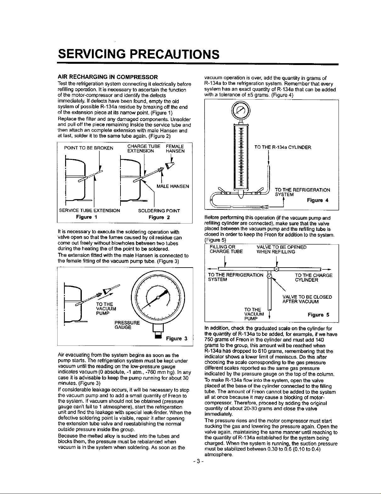
system of possible R-134a residue by breaking off the end
of the extension piece at its narrow point. (Figure 1)
Replace the filter and any damaged components. Unsolder
and pull off the piece remaining inside the service tube and
then attach an complete extension with male Hansen and
at last, solder it to the same tube again. (Figure 2)
POINT TO BE BROKEN
SERVICE TUBE EXTENSION
Figure 1
It is necessary to execute the soldering operation with
valve open so that the fumes caused by oil residue can
come out freely without blowholes between two tubes
during the heating the of the point to be soldered.
The extension fitted with the male Haasen is connected to
the female fitting of the vacuum pump tube. (Figure 3)
CHARGE TUBE FEMALE
EXTENSION HANSEN
,_ MALE HANSEN
SOLDERING POINT
Figure 2
vacuum operation is over, add the quantity in grams of
R-134a to the refrigeration system. Remember that every
system has an exact quantity of R-134a that can be added
with a tolerance of -+5grams. (Figure 4)
()
I ' TOTBiR-t ooYuNoER
TOTHEREF , E TION
'_ SY)TEM Figure 4
Before performing this operation (if the vacuum pump and
refilling cylinder are connected), make sure that the valve
placed between the vacuum pump and the refillingtube is
dosed in order to keep the Freon for addition to the system.
(Figure 5)
FILLING OR VALVE TO BE OPENED
CHARGE TUBE WHEN REFILLING
i!c
PRESSURE
GAUGE
Figure 3
Air evacuating from the system begins as soon as the
pump starts. The refrigeration system must be kept under
vacuum until the reading on the low-pressure gauge
indicates vacuum (0 absolute, -1 atm., -760 mm hg). In any
case it is advisable to keep the pump running for about 30
minutes. (Figure 3)
If considerable leakage occurs, it will be necessary to stop
the vacuum pump and to add a small quantity of Freon to
the system. If vacuum should not be obtained (pressure
gauge can't fall to 1 atmosphere), start the refrigeration
unit and find the leakage with special leek-tinder. When the
defective soldering point is visible, repair it after opening
the extension tube valve and reestablishing the normal
outside pressure inside the group.
Because the melted alloy is sucked into the tubes and
blocks them, the pressure must be rebalansed when
vacuum is Inthe system when soldering. As soon as the
TO THE REFRIGERATION TO THE CHARGE
SYSTEM CYLINDER
VALVE TO BE CLOSED
AFTER VACUUM
TO TH E
VACUUM _ Figure 6
PUMP
In addition, check the graduated scale on the cylinder for
the quantity of R-134a to be added, for example, if we have
750 grams of Freon in the cylinder and must add 140
grams to the group, this amount will be reached when
R-134a has dropped to 610 grams, remembering that the
indicator shows a lower limit of meniscus. Do this after
choosing the scale corresponding to the gas pressure
different scales reported as the same gas pressure
indicated by the pressure gauge on the top of the column.
To make R-134a flow into the system, open the valve
placed at the base of the cylinder connected to the filling
tube. The amount of Freon cannot be added to the system
all at once because it may cause a blocking of motor-
compressor. Therefore, proceed by adding the original
quantity of about 20-30 grams and close the valve
immediately.
The pressure rises and the motor compressor must start
sucking the gas and lowering the pressure again. Open the
valve again, maintaining the same manner until reaching to
the quantity of R-134a established for the system being
charged. When the system is running, the suction pressure
must be stabilized between 0.30 to 0.6 (0.10 to 0.4)
atmosphere.
-3-
2001.06.01 160/120
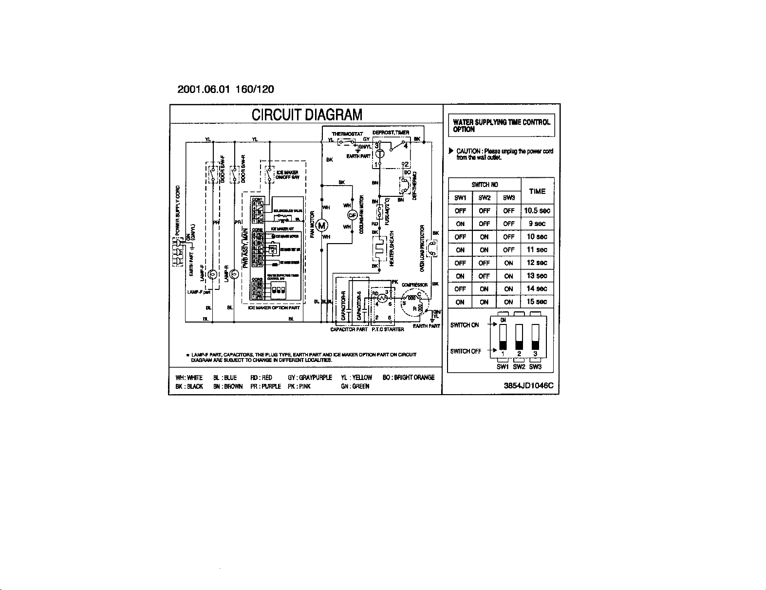
CIRCUITDIAGRAM
WATERSUPR.Y_GTIMECONtrOL
0PIION
YL YL ..... GY ..... BK
LI" _ I........ 131(
J_ _18 _ _ '_ _ I
' , ' "ICENN(F_ I :
I I I _ '
h_ !lp_r
r-,'_ _ i , I>: ! I_ -- ["" "'1 r
,,,;,,...,o_,,_.._....
- ........_- _3_........
,,_LAMP.F phRr, CA_AC, flrORr_, _,_ PLUG _tpF_ F.jbR_ p/_T ANO K_ _ Op11ON p_ O_I Cl_ _ _f]TCH OFF --_, 2
WH:_II_ BL:BLUE RD:RED QY:QRA_JRPLE YL:Y_.LOW BO:BRIGHTOPJ_GE
BK:BLACK BId:BROWN PR:PURR.E PK:RNK GN:GREB 3854JD1046C
fromllm_ oulbl.
SWaN HO
SWl SW2 SW3
OFF OFF OFF 10.5 Se_
ON OFF OFF 9 80c
OFF ON OFF 10 SeC
ON ON OFF 11 sec
OFF OFF ON 12 $ec
ON OFF _ 13 sec
OFF ON ON 14 sec
ON ON ON 15se¢
F"3 r'-3 F--]
oN
SW1 SW2 SW3
TIME
2. PARTS IDENTIFICATION
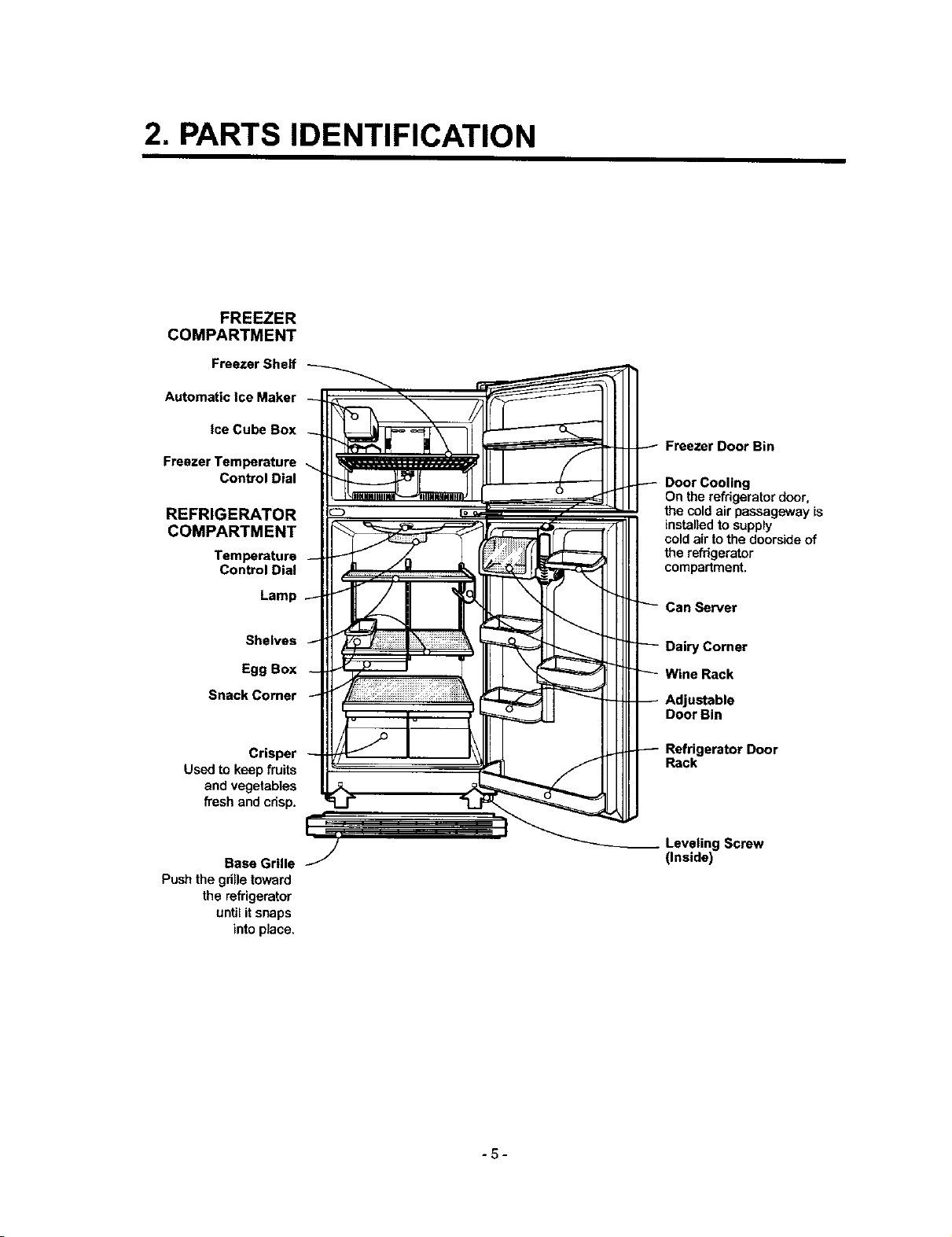
FREEZER
COMPARTMENT
Freezer Shelf
Automatic Ice Maker
ice Cube Box
Freezer Temperature
Control Dial
REFRIGERATOR
COMPARTMENT
Temperature
Control Dial
Lamp
Freezer Door Bin
Door Cooling
On the refrigerator door,
the cold air passageway is
installed to supply
coldair tothe door,sideof
the refrigerator
compartment.
Shelves
Egg Box
Snack Comer
Crisper
Usedto keep fruits
and vegetables
fresh and cdsp.
Base Grille
Push the gdlle toward
the refrigerator
until itsnaps
intoplace.
Dairy Corner
Door Bin
Refrigerator Door
Rack
Leveling Screw
(Inside)
-5-
4. ADJUSTMENT
4-1 COMPRESSOR
4-%1 Role
The compressor intakes low temperature and low pressure
gas evaporated from evaporator of the refrigerator, and
condenses this gas to high temperature and high pressure
gas, and then plays delivering role to condenser.
4-1-2 Composition
The compressor includes overload protection. The PTC
starter and aLP (overload protector) are outside the
compressor. Since the compressor is manufactured to
tolerances of I micron, and is sealed in a dust - and
moisture - free environment, use extreme caution when
repairing it.
4,1-3 Note for Usage
(1) Be careful not to allow over-voltage and over-current.
(2) No Strike
If applying forcible power or strike (dropping or careless
handling), poor operation and noise may occur.
(3) Use proper electric components appropriate to the
Compressor.
(4) Note to Keep Compressor.
If Compressor gets wet in the rain and rust in the pin of
Hermetic Terminal, the result may be poor operation
and poor contact may cause.
(5) Be careful that dust, humidity, and welding flux don't
contaminate the compressor inside when replacing the
Compressor. Dust, humk_ity, and flux due to welding
which contaminates the cylinder may cause Iockage
and noise.
4-2 PTC-STARTER
4-2-1 Composgion of PTC-Starter
(1) PTC (Positive Temperature Coefficient) is a no-cantact
semiconductor starting device which uses ceramic
material consisting of BaTiO3.
(2) The higher the temperature is, the higher the resistance
value. These features are used as starting device for
the Motor.
4-2-2 Role of PTC-Starter
(1) PTC is attached to Hermetic Compressor used for
Refrigerator, Show Case, and starling Motor.
(2) Compressor for household refrigerator applies to
single-phase induction Motor.
For normal operation of the single-phase induction
motor, in the starting operation flows in both main coil
and sub-coiL After the starting is over, the current in
subeoil is cut off. The proper features of PTC play all
the above roles. So, PTC is used as e motor starting
device.
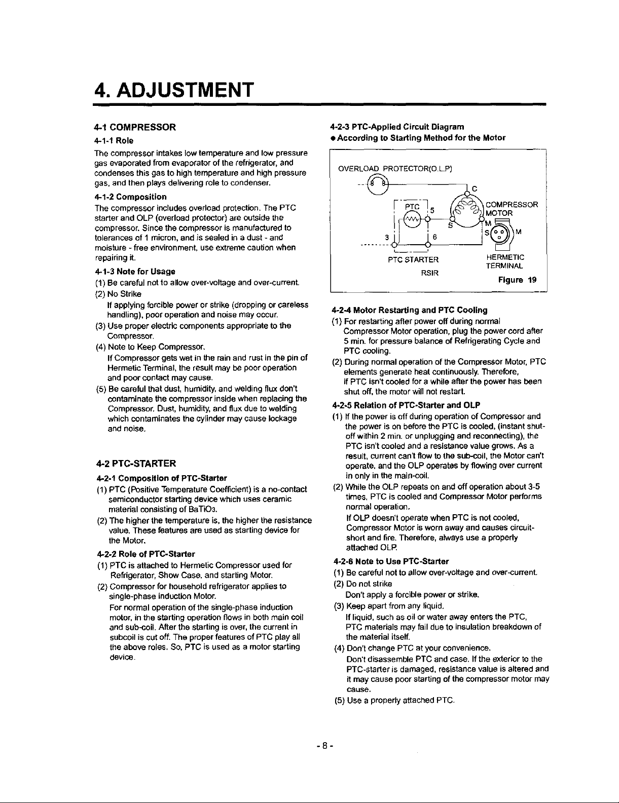
4-2,3 PTC-Applied Circuit Diagram
• According to Starting Method for the Motor
OVERLOAD PROTECTOR(O.L.P)
F--b%-7o / COMPRESSOR
.....
PTC STARTER HERMETIC
RS)R
4-2-4 Motor Restarting and PTC Cooling
(1) For restarting after power off during normal
Compressor Motor operation, plug the power cord after
5 min. for pressure balance of Refrigerating Cycle and
PTC cooling.
(2) During normal operation of the Compressor Motor, PTC
elements generate heat continuously. Therefore,
if PTC isn't cooled for a while after the power has been
shut off, the motor will not restart.
4,2-5 Relation of PTC-Starter and aLP
(1) If the power is off during operation of Compressor and
the power is on before the PTC iscooled, (instant shut-
off within 2 min. or unplugging and reconnecting), the
PTC isn't cooled and a resistance value grows, As e
result, current can't flow to the sub-coil, the Motor can't
operate, and the aLP operates by flowing over current
in only in the main-coil.
(2) While the aLP repeats on and off operation about 3-5
times, PTC is cooled and Compressor Motor performs
normal operation.
If aLP doesn't operate when PTC is not cooled,
Compressor Motor is worn away and causes circuit-
short and fire. Therefore, always use a properly
attached aLP.
4-2-6 Note to Use PTC-Starter
(1) Be careful not to allow over-voltage and over-current.
(2) Do not strike
Don't apply a forcible power or strike.
(3) Keep apart from any liquid.
If liquid, such as oil or water away enters the PTC,
PTC mataria]s may fail due to insulation breakdown of
the material itself.
(4) Don't change PTC at your convenience.
Don't disassemble PTC and case. If the exterior to the
PTC-starter is damaged, resistance value is altered end
it may cause poor starting of the compressor motor may
cause.
(5) Use a properly attached PTC.
TERMINAL
Figure 19
-8-
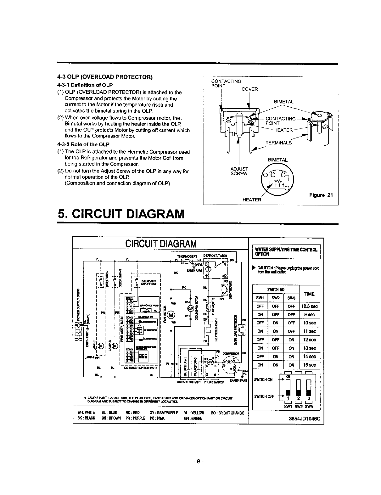
4-30LP (OVERLOAD PROTECTOR)
4-3-1 Definition of OLP
(1) OLP (OVERLOAD PROTECTOR) is attached to the
Compressor and protects the Motor by cutting the
current to the Motor if the temperature rises and
activates the bimetal spring in the OLP.
(2) When over-voltage flows to Compressor motor, the
Bimetal works by heating the heater inside the OLP,
and the OLP protects Motor by cutting off current which
flows to the Compressor Motor,
4-3-2 Role of the OLP
(1) The OLP is attached tothe Hermetic Compressor used
for the Refrigerator and prevents the Motor Coil from
being started in the Compressor.
(2) Do not turn the Adjust Screw of the OLP in any way for
normal operation of the OLR
(Composition and connection diagram of OLP)
5. CIRCUIT DIAGRAM
CONTACTING
POINT
_BIMETAL
SCREW
ADJUST
COVER
HEATER
BIMETAL
Figure 21
-9-
SW2 SW3
OFF OFF 10.5IW
OFF OFF 9
ON OFF 10SeC
ON OFF 11sec
OFF ON 12sec
b'l_gl_ONNO ON TIME
OFF ON t3sec
ON ON 14 sec
15sec
_0FF 2 3
SW1SW2 SW3
3854JD1046C
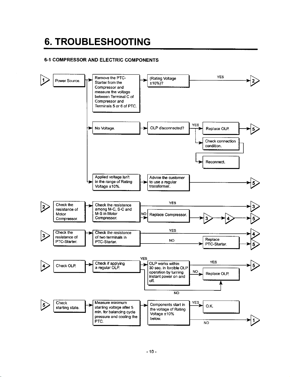
6. TROUBLESHOOTING
6-1 COMPRESSOR AND ELECTRIC COMPONENTS
Power Source.
Check the _ Check the resistance
resistance of I [ among M-C, S-C and
Motor I I Compressor.Compressor.
Remove the PTC-
Starter from the
Compressor and
measure the voltage
between Terminal C of
Compressor and
Terminals 5 or6 of PTC.
llaNo Voltage.
Applied voltage isn't
_,. in the range of Rating
Voltage -+10%.
I I M-S in Motor
__ (RatingVoltage YES
_+10%)? I •[_
OLP disconnected?
[_lCheckconnection
| condi_on, h
to use a regular
Advisethe customer I •[_
transformer.
N_O YES _._
Replace Compresson
Replace OLR
L_ Reconne_. I
Check the _ Check the resistance
resistance of I I of two terminals in
PTC-Starter. I I PTC-Starter.
YES
[4_ Check OLR i--_ Check if applying _,_ OLP works within,,30 sec. in forcible OLP, , YES •_
lea re_:Jular OLR
I I I operation by turning _ Replace OLR
I I instant power on and I r I I
YES
NO • PTC-Sta_er.
Replace
II°,,. I J
NO
[_ Check L._ Measure minimum
starting state. I v I starting voltage after 5
I I rain. for balancing cycle
/pressure and cooling the
/ PTC.
I_ Components start in
Voltage _+10%
the voltage of Rating O.K. I •[_
below. / NO
-10-
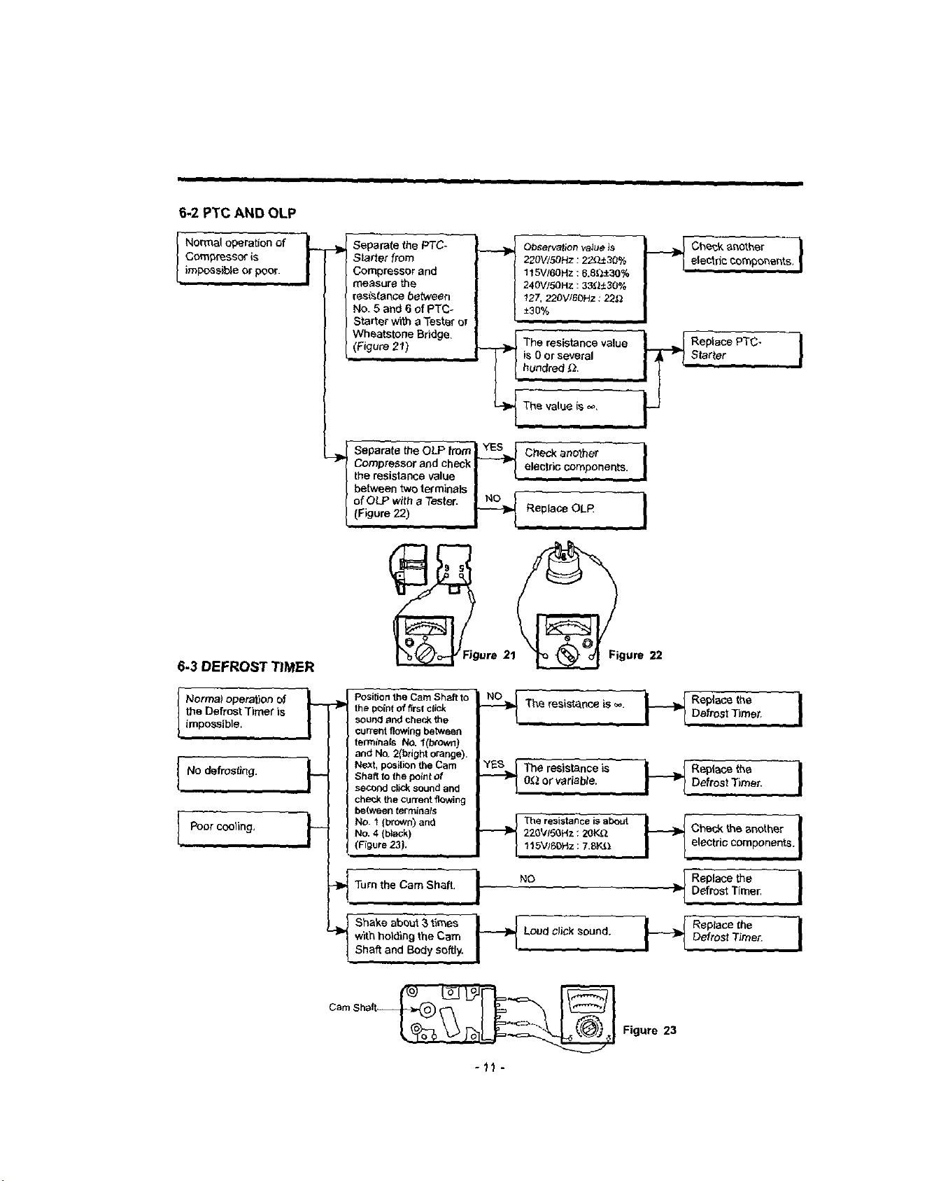
6-2 PTC AND OLP
%,
Normal operation of _ __
Compressor {s
[
impese_:de or poor.
/
ii • i i
Separate the PTC-
Starter from
Compressor and
measure the
resistance between
No. 5 and 6 of PTC-
Starter with a Tester or
Wheatstone Bddge.
(Figure 21)
J Separata the OLP from_eck another I
-_( Compressor and check I --J'_ electric components
the resistance value ..
/ between two terminals I i
{ of OLPwithaTester. | NO ] _ _l
] (F,gure 22) _ Rep,ace OLP
220V/50Hz : 22_)..t30 %
115V/60Hz : 6.81_-+30%
240V/S0HZ : 33_30%
Observation va_ue Js
127, 220V/60Hz : 22£_
±30%
The resistance value
is 0 or several
___ Replace PTC-
s.ta_ter ]
I
I
6-3 DEFROST TIMER
Normal opera)on of
the Defrost Timer is
[
impossible,
No defrosting.
Poor cooling.
l,,
_Jgure 21_gure
Position the Cam Shaft to '
the point of f_rst click
sound and check the
current flowingbetween
terminals NO. l(brown)
and No, 2(bright orange).
Next, position the Cam
F
Shaft to the point of
second click sound and
che_.k the current flowing
between terminals
No. I (broWn) and
No. 4 (black)
(Figure 23).
-_Tum the Cam Shaft. I NO
with holdingthe Cam cud click
S,,,eo o ,.eeV, ?°°"'"
Shaft and Body softly.
22
-'_-?-_Theresistanceis=" i"_ R_PI_:et"eDe_rost"nme_. ]
.._ The resistance is
Of_ or variable... _ Replace the
115,V}6DHz_7,SY_;t electric components. I
I__ Replace _he
Figure 23
Defrost T)mer. I
_ ReplacetheDefrostTimer. )
Defrost Timer. I
-11 -
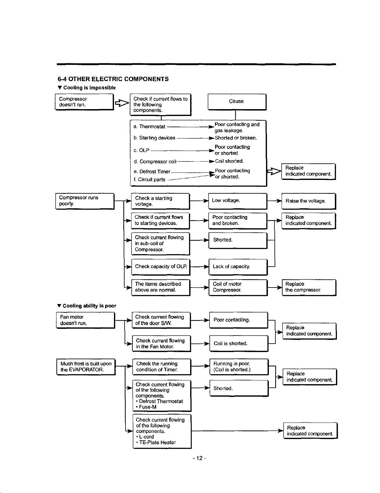
6-4 OTHER ELECTRIC COMPONENTS
• Cooling is impossible
doesn't run. _ the following I Cause
components. I
a, Thermostat _ Poor contacting and
b. Starting devices _ Shorted or broken,
c. OLP m or shorted.
d. Compressor coil
e. Defrost Timer _ Poor contacting
f. Circuit parts
poorly.C°mpress°rruns i'm "_ CheCkvoltage.astarting
to starting devices, and broken,
__ Chee_ifeurrentfl_.qs _ PoorcontaeUng
in sub-coil of
_ heck current floWing _-_ Shorted.
Compressor.
_ Check capacity of OLR _ Lack of capacity. _--
, I
gas leakage.
Poor contacting
Coilshorted.
-_or shorted.
Low voltage.
I
_ Replaco
indicatedcomponent, I
_ Raise the voltage. I
I--f= ,0 coooo ,I
• Cooling ability is poor
doesn't run.
Fan motor t--_
above are normal. Compressor. the compressor.
}_ The items doscribed I_ C°il of mot°r I_ Replace I
_1 r
of the door S/IV.
Check current flowing _ Poor contacting.
Check current flowing _ Coil is shorted,
in the Fan Motor.
Check the running _ Running Jspoor.
condition of Timer. I ri (Coil is shorted.)
Check current flowing ] _[
components.
• Defrost Thermostat
of the following _-_ Shorted.
• Fuse-M
Check current flowing
of the following
components.
• L-cord
• TE*PIata Heater
I-I
I
-12-
_ Replace
indicatedcomponent.I
indicatedcomponent.
Replace I
Replaceindicted component. I
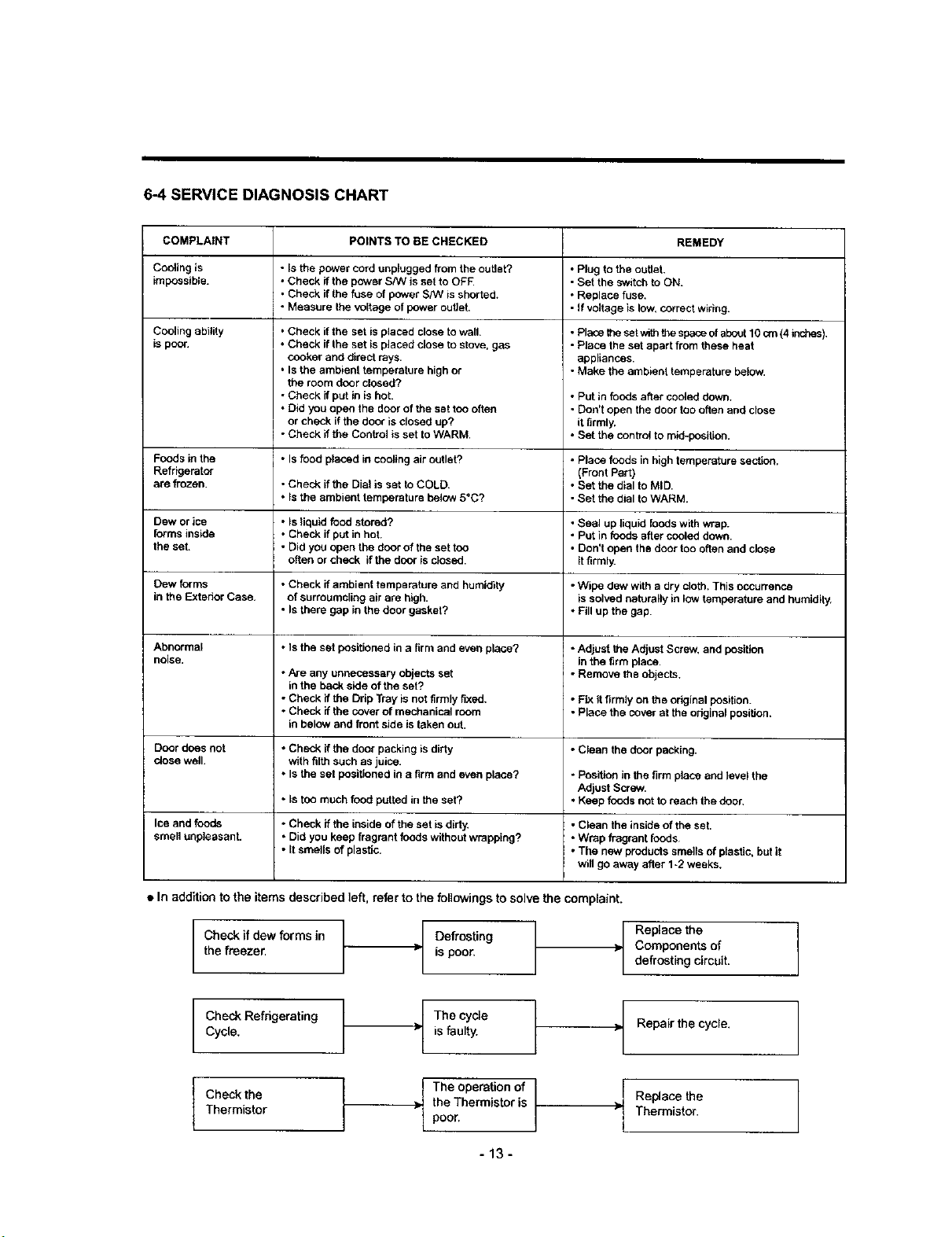
6-4 SERVICE DIAGNOSIS CHART
COMPLAINT POINTS TO BE CHECKED REMEDY
Cooting is • Is the power cord unplugged from the outlet? • Plug to the outlet.
impossible. • Check if the power S/W is set to OFF. • Set the switch to ON.
Cooling ability
is poor.
Foods in the • Is food placed in cooling air outlet? • Place foods in high temperature sectlan.
Refrigerator (Front Part)
are frozen. • Check if the Dial is set toCOLD • Set the dlal to MID.
Dew or ice • Is liquid food stored? • Seal up fiquid foods with wrap.
forms inside • Check if put in hot. • Put in foods after cooled down.
the set. • Did you open the door of the set too • Don't open the door too often and close
Dew forms • Check if ambient temperature and humidity • Wipe dew with adry cloth. This occurrence
in the Exterior Case. of surroumcling air are high. is solved naturally in low temperature and humidity.
Abnormal * Is the set positioned in a firm and even place? • Adjust the Adjust Screw. and position
noise, in the tirm I_ace.
Door does not • Check if the door packing is dirty • Clean the door packing.
ctose well, with filth such as juice.
Ice and fuods • Check if the inside of the set is dirty, • Clean the inside of the set.
smell unpleasant. • Did you keep fragrant foods without wrapping? • Wrap fragrant foods
• Check if the fuse of power S/W is shorted. • Replace fuse.
• Measure the voltage of power outieh - If voltage is low, correct wiring.
• Check if the set is placed close to wall.
• Check if the set is placed close to stove, gas
cooker and direct rays.
• Is the ambient temperature high or
the room door closed?
• Check if put in is hot.
• Did you open the door of the set too often
or check if the door is closed up?
• Check if the Control is set to WARM.
• Is the ambient temperature below 5_C? • Set the d}al to WARM.
often or check if the door is closed, it firmly.
• Is there gap in the door gasket? • Fill up the gap.
• Are any unnecessary objects set • Remove the objects.
in the back side of the set?
• Check if the Drip Tray is not firmly fixed. * Fix it firmly on the original position.
• Check if the cover of mechanical room • Place the cover at the odginal position.
in below and front side is taken out.
• Is the set positioned in a firm and even place? • Position in the firm place and level the
• Is too much food putted in the set? • Keep foods not to reach the door,
• it smells of plastic. • The new products smefis of plastic, butit
• Placethesetwiththespeceofabout10cm(4 inches).
- Place the set apart from these heat
appliances.
• Make the ambienttemperaturebelow.
• Put in foods after cooled down.
• Don't open the door too often and close
it firmly.
• Set the control to mid-position.
Adjust Screw.
wi;l go away after 1-2 weeks.
• In addition to the items described ]eft, refer to the followings to solve the complaint.
Check Jfdew forms in Defrosting /
the freezer, is poor. •
Check Refrigerating
Cycle.
Check the
Thermistor
isfaulty.
f he cycle
the Thermistor is
The operation of
poor,
-13-
Components of
Replace the ]
defrosting circuit.
[
Repair the cycle. 1
Replace the
Thermistor.
/
 Loading...