

LG LRTB2021W, LRTB1821W Owner’s Manual
SERVICING PRECAUTIONS
AIR RECHARGING IN COMPRESSOR
Test the refrigeration system connecting it electrically before
refilling operation. It is necessary to ascertain the function
of the motor-compressor and identify the defects
immediately. If defects have been found, empty the old
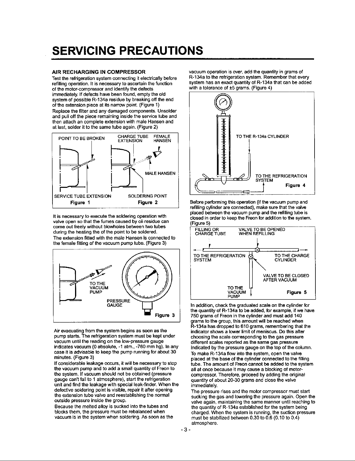
system of possible R-134a residue by breaking off the end
of the extension piece at its narrow point. (Figure 1)
Replace the filter and any damaged components. Unsolder
and pull off the piece remaining inside the service tube and
then attach an complete extension with male Hanson and
at last, solder it to the same tube again. (Figure 2)
POINT TO BE BROKEN CHARGE TUBE FEMALE
'.J__ i MALE HANSEN
SERVICE TUBE EXTENSION SOLDERING POINT
Figure 1 Figure 2
EXTENSION HANSEN
It is necessary to execute the soldering operation with
valve open so that the fumes caused by oil residue can
come out freely without blowholes between two tubes
during the heating the of the point to be soldered.
The extension fitted with the male Hanson is connected to
the female fitting of the vacuum pump tube. (Figure 3)
vacuum operation is over, add the quantity in grams of
R-134a to the refrigeration system. Remember that every
system has an exact quantity of R-134a that can be added
with a tolerance of +5 grams. (Figure 4)
TO THE R-134a CYLINDER
:__ TO THE REFRIGERATION
SYSTEM
I Figure 4
Before performing this operation (if the vacuum pump and
refilling cylinder are connected), make sure that the valve
placed between the vacuum pump end the refillingtube is
closed in order to keep the Frecn for addition to the system.
(Figure 5)
FILLING OR VALVE TO BEOPENED
CHARGE TUBE WHEN REFILLING
Air evacuating from the system begins as soon as the
pump starts. The refrigeration system must be kept under
vacuum until the reading on the low-pressure gauge
indicates vacuum (0 absolute, -1 arm., -760 mm hg). In any
case it is advisable to keep the pump running for about 30
minutes. (Figure 3)
If considerable leakage occurs, itwill be necessary to stop
the vacuum pump and to add a small quantity of Freon to
the system. If vacuum should not be obtained (pressure
gauge can't fall to 1 atmosphere), start the refrigeration
unit and find the leakage with special leak-finder. When the
defective soldering point is visible, repair it after opening
the extension tube valve and reestablishing the normal
outside pressure inside the group.
Because the melted alloy is sucked into the tubes and
blocks them, the pressure must be rebalanced when
vacuum is in the system when soldering. As soon as the
TO THE REFRIGERATION TO THE CHARGE
SYSTEM CYLINDER
VALVE TO BE CLOSED
AFTER VACUUM
TO THE
VACUUM [ Figure 5
PUMP
T
In addition, check the graduated scale on the cylinder for
the quantity of R-134a to be added, for example, if we have
750 grams of Freon in the cylinder and must add 140
grams to the group, this amount will be reached when
R-134a has dropped to 610 grams, remembering that the
indicator shows a lower limit of meniscus. Do this after
choosing the scale corresponding to the gas pressure
different scales reported as the same gas pressure
indicated by the pressure gauge on the top of the column.
To make R-134a flow into the system, open the valve
placed at the base of the cylinder connected to the filling
tube. The amount of Fraon cannot be added to the system
all at once because it may cause a blocking of motor-
compressor. Therefore, proceed by adding the original
quantity of about 20-30 grams and close the valve
immediately.
The pressure rises and the motor compressor must start
sucking the gas and lowering the pressure again. Open the
valve again, maintaining the same manner until reaching to
the quantity of R-134a established for the system being
charged. When the system is running, the suction pressure
must be stabilized between 0.30 to 0.6 (0.10 to 0.4)
atmosphere.
"3-
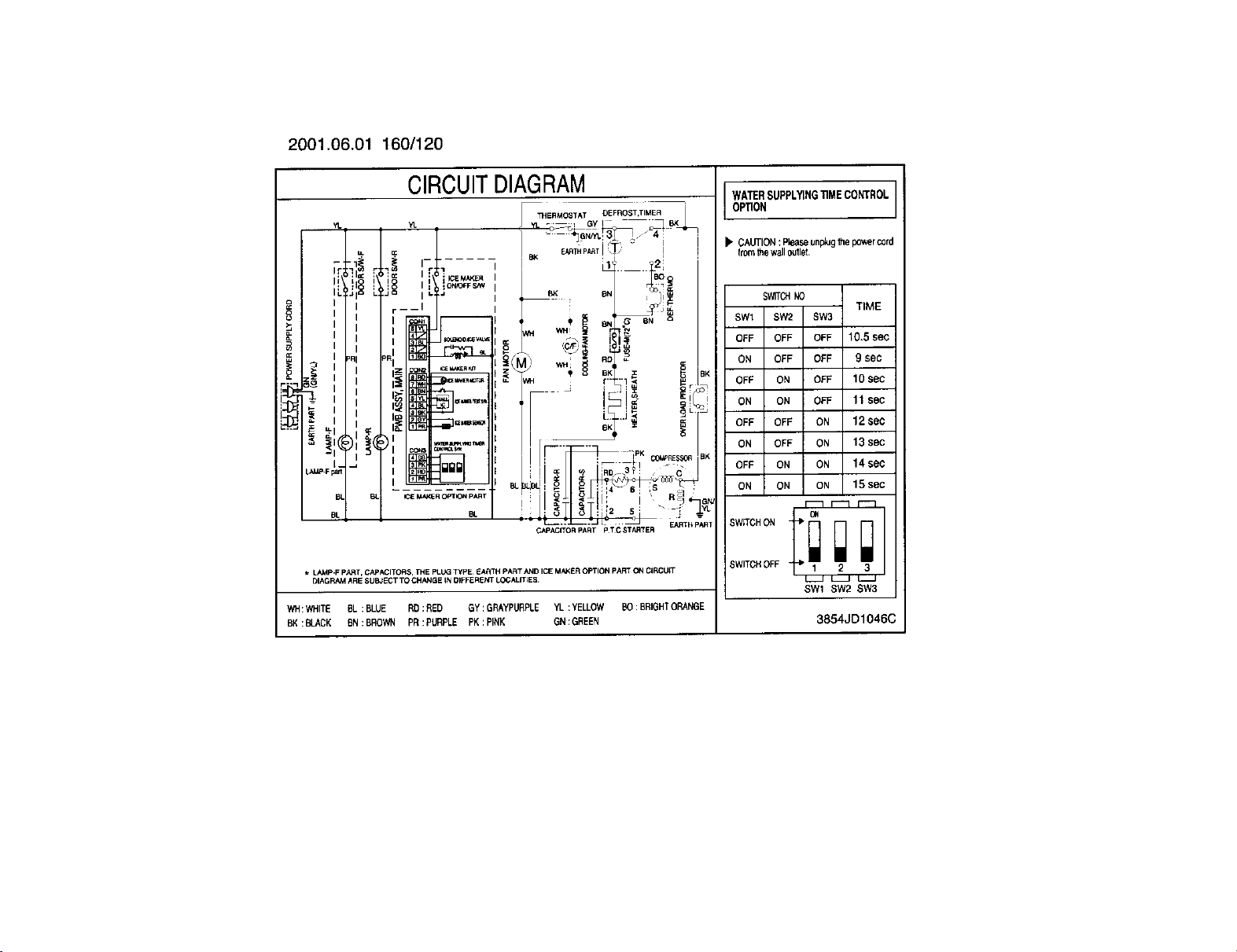
2001.06.01 160/120
CIRCUITDIAGRAM
YL YL
LL OC
;i__ ,_ '_i_
I!! h'_ := I I 'K:E_','XE.
=_ IL_'_ J_ ,._
>_ I
i Z i _ u<
1 n x "="_=
= _ll(_),___(,,ll[__1=. =-,......
LAMP-F paxt
BL _ ,_E _A_Q¢R OPTION P_T
OL BL
* LAMP-F pART, CAPACITORS, THE PLUG _pE, _AR_H pA_T AND ICE MAKER OPTION pART C_NCIRCUIT
WH:WHITE BL:BLUE RD:NED GY:GRAYPURPLE YL :YELLOW BO: BRIGHTORANGE
BK: BLACK _.N:BROWN PR ; PURPLE PK:PINK ON:GREEN
I i :_ _ON_O'FFSPN
r----I
-- I _ 8N G SN
_'_ERMOSTAT_} GYIDEFROST'TIMERj-_T 8K
',
I _ °" , ,_
_M) _ _ .D, e
II .... = ==
' I"__!i_ - '-;'_
L'_.!_-_-_,_i:__ _.t_,
;ApA_iTOR PART p T C STABTER
_LITtES
WATERSUPPLYINGTIMECONTROL
OPTION
)" CAUTION:Pleaseunp_Jgthepowercord
fromthewalloutlet.
S_TCHNO
SW1 SW2 SW3
OFF OFF OFF 10.5 sec
ON OFF OFF 9 sec
OFF ON OFF 10 sec
ON ON OFF 11 BOG
OFF OFF ON 12 sec
ON OFF ON 13 sec
OFF ON ON 14 sec
ON ON ON 15 sec
_ r-'3 r'-]
SWITCHOFF _" 1 2 3
SW1 SW2 SW3
TIME
o_
3854JD1046(
2. PARTS IDENTIFICATION
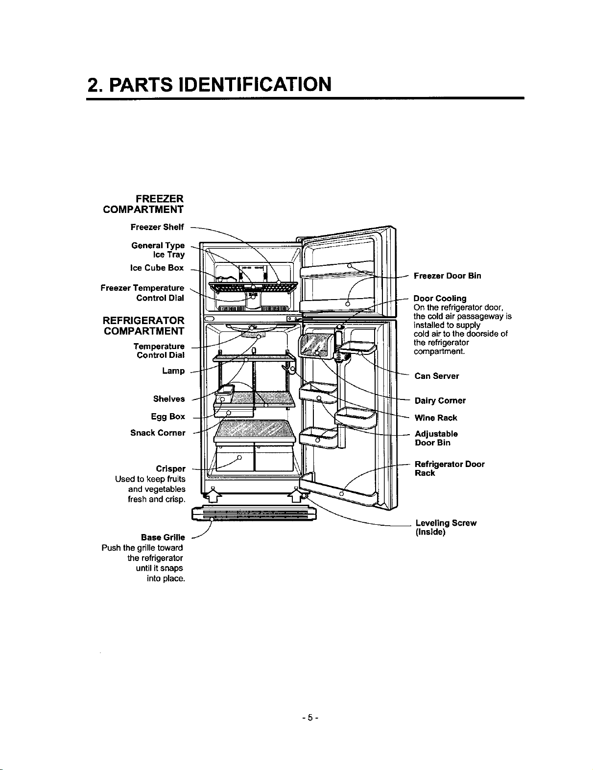
FREEZER
COMPARTMENT
Freezer Shelf
GeneralType
Ice Tray
Ice Cube Box
Freezer Temperature
Control Dial
REFRIGERATOR
COMPARTMENT
Temperature
Control Dial
Lamp
Freezer Door Bin
Door Cooling
On the refrigerator door,
the cold air passageway is
installed to supply
coldair tothe doorsideof
the refrigerator
compartment.
Can Server
Shelves
Egg Box
Snack Corner
Crisper
Used to keep fruits
and vegetables
fresh and crisp.
Base Grille
Pushthe grilletoward
the refrigerator
until it snaps
intoplace,
Dairy Corner
Wine Rack
Adjustable
Door Bin
Refrigerator Door
Rack
LevelingScrew
(Inside)
-5-
3. DISASSEMBLY
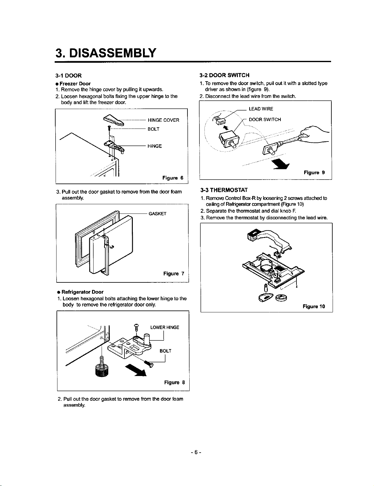
3-1 DOOR
• Freezer Door
1. Remove the hinge cover by pulling it upwards.
2. Loosen hexagonal bolts fixing the upper hinge to the
body and liftthe freezer door.
HINGE COVER
HINGE
BOLT
Figure 6
3. Pull out the door gasket to remove from the door foam
assembly,
GASKET
3-2 DOOR SWITCH
1. To remove the door switch, pull out it with a slotted type
driver as shown in (figure 9).
2. Disconnect the lead wire from the switch.
LEAD WIRE
_ DOOR SWITCH
:S 2:2
Figure 9
3-3 THERMOSTAT
1. Remove Control Box-R by loosening2 screws attached to
ceilingof Refi'igemtorcompad_ent (Figure 10)
2. Separate the thermostat and dial knob F.
3. Remove the thermostat by disconnecting the lead wire.
Figure 7
• Refrigerator Door
1. Loosen hexagonal bolts attaching the lower hinge to the
body to remove the refrigerator door only.
<_ LOWER HINGE
BOLT
__J
Figure 8
2. Pull out the door gasket to remove from the door foam
assembly.
Figure 10
-6-
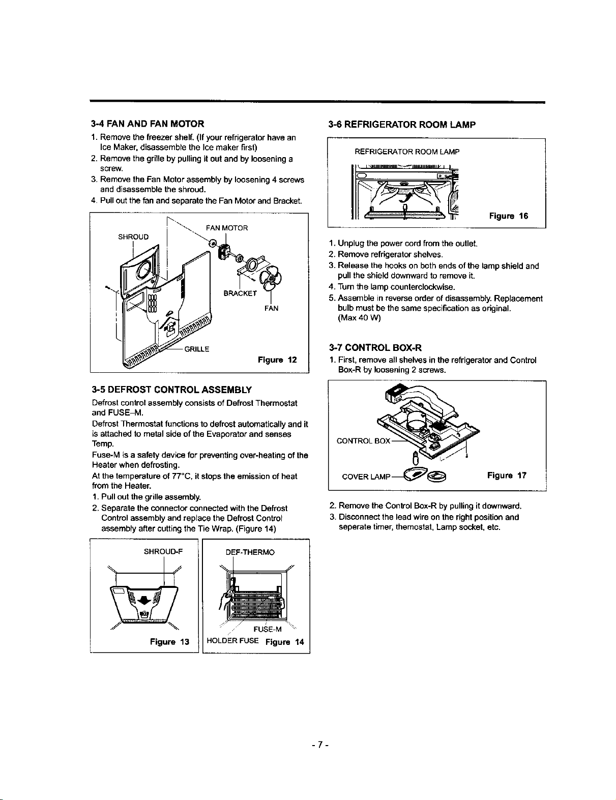
3-4 FAN AND FAN MOTOR
1. Remove the freezer shelf. (If your refrigerator have an
Ice Maker, disassemble the Ice maker first)
2. Remove the grille by pulling it out and by loosening a
screw.
3. Remove the Fan Motor assembly by loosening 4 screws
and disassemble the shroud.
4. Pull out the fan and separate the Fan Motor and Bracket.
_'_. FAN MOTOR
SHROUD
FAN
3-6 REFRIGERATOR ROOM LAMP
REFRIGERATOR ROOM LAMP
............................
Figure 16
1. Unplug the power cord from the outlet,
2. Remove refrigerator shelves.
3. Release the hooks on both ends of the lamp shield and
pull the shield downward to remove it.
4. Turn the lamp counterclockwise.
5. Assemble in reverse order of disassembly. Replacement
bulb must be the same specification as original.
(Max 40 W)
-GRILLE
Figure 12
3-5 DEFROST CONTROL ASSEMBLY
Defrost control assembly consists of Defrost Thermostat
and FUSE-M.
Defrost Thermostat functions to defrost automatically and it
is attached to metal side of the Evaporator and senses
Temp.
Fose-M is a safety device for preventing over-heafing of the
Heater when defrosting.
At the temperature of 77°C, it stops the emission of heat
from the Heater.
1. Pull out the grille assembly.
2. Separate the connector connected with the Defrost
Control assembly and replace the Defrost Control
assembly after cutting the Tie Wrap. (Figure 14)
SHROUD-F
Figure 13
DEF_HERMO
FUSE-M
HOLDER FUSE Figure 14
3-7 CONTROL BOX-R
1. First, remove all shelves in the refrigerator and Control
Box-R by loosening 2 screws.
A
COVER LAMP_@ Figure 17
2. Removethe Control Box-Rby pulling it downward.
3. Disconnectthe lead wireonthe rightpositionand
seperatetimer,themostat,Lampsocket,etc.
-7-
 Loading...