

LG LRSPC2661T Owner’s Manual
WARNINGS AND PRECAUTIONS FOR SAFETY
Please observe the following safety precautions inorder to
use safely and correctly the refrigerator and to prevent
accident and danger during repair.
1. Be care of an electric shock. Disconnect power cord
from wall outlet and wait for more than three minutes
before replacing PWB parts. Shut off the power
whenever replacing and repairing electde components.
2. When connecting power cord, please wait for more than
five minutes after power cord was disconnected from the
wall outlet.
3. Please check if the power plug is pressed down by the
refrigerator against the wall tf the power plug was
damaged, it may cause fire or electric shock.
4. ff the wall outlet is over loaded, it may cause fire. Please
use its own individual electrical outlet for the refrigerator.
5. Please make sure theoutletispropedy earthed,
particularlyin wet or damp area.
6, Use standard electrical components when replacing
them.
7. Make sure the hook is correctly engaged.
Remove dust and foreign matedals from the housing
and connecting parts.
8. Do notfray. damage, machine, heavily bend, pullout,
or twist the power cord.
Please check the evidence of moisture intrusion in the
electrical components. Replace the parts or mask it
with insulation tapes if moisture intrusion was
confirmed.
10. Do not touch the icomaker with hands or tools to
confirm the operation of geared motor.
11. Do not let the customers repair, disassemble, and
reconst_ct the refdgerator for themselves. It may
cause accident, electTic shock, or fire.
12. Do not store flammable materials such as ether,
benzene, alcohol, chemicals, gas, or medicine in the
refrigerator.
13. Do not put flower vase, cup, cosmetics, chemicals,
etc., or container with full of water on the top of the
refrigerator.
14. Do not put glass bottles with full of water into the
freezer. The contents shall freeze and break the glass
bottles.
15. When you scrap the refrigerator, please disconnect the
door gasket first and scrap it where children are not
accessible.
-3-
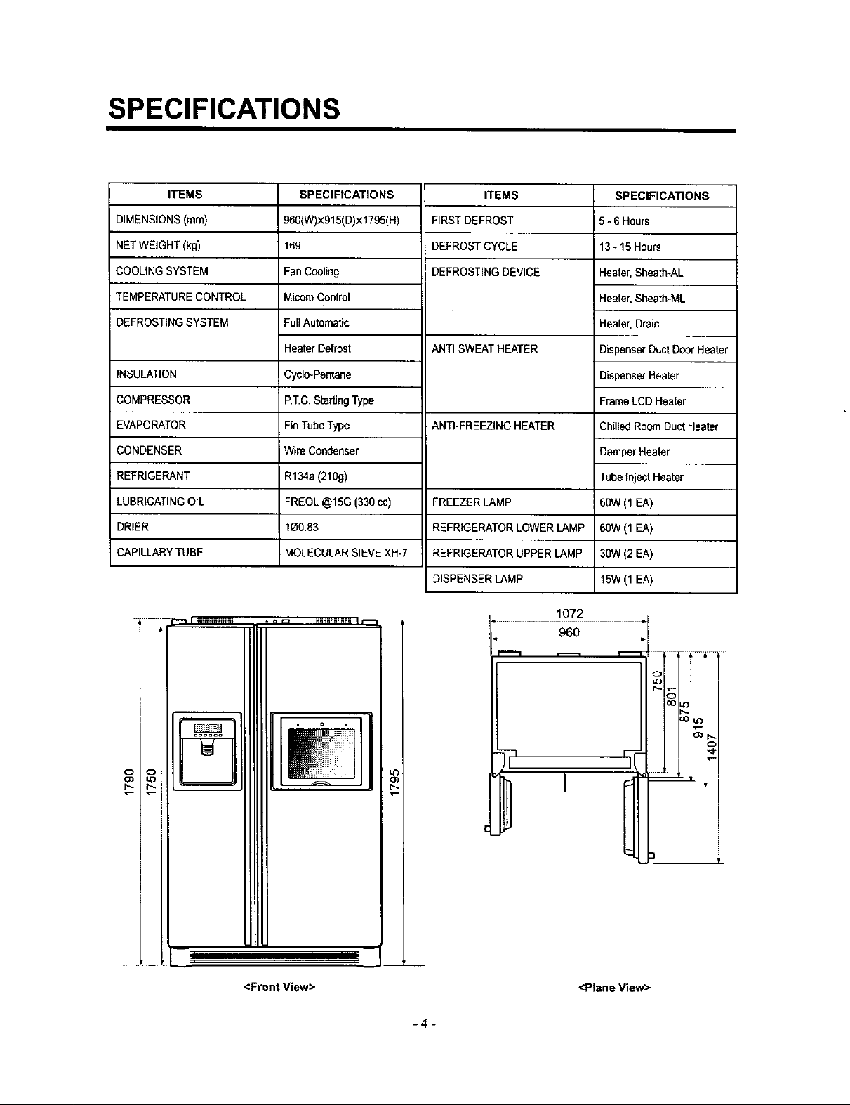
SPECIFICATIONS
ITEMS
DIMENSIONS (ram)
NET WEIGHT (kg)
COOLING SYSTEM
TEMPERATURE CONTROL
DEFROSTING SYSTEM
INSULATION
COMPRESSOR
EVAPORATOR
CONDENSER
REFRIGERANT
LUBRICATING OIL
DRIER
CAPILLARY TUBE
SPECIFICATIONS
960(W)x915(D)×1795(H)
169
Fan Cooling
MicomControl
FullAutomatic
Heater Defrost
Cyclo-Pentane
P,T.C,Starting Type
Fin Tube Type
Wire Condenser
R134a (210g)
FREOL @15G (330 cc)
1_0.83
MOLECULAR SIEVE XH-7
ITEMS
FIRST DEFROST
DEFROST CYCLE
DEFROSTING DEVICE
ANTI SWEAT HEATER
ANTI-FREEZING HEATER
FREEZER LAMP
REFRIGERATOR LOWER LAMP
REFRIGERATOR UPPER LAMP
DISPENSER LAMP
SPECIFICATIONS
5 - 6 Hours
13- 15 Hours
Heater, Sheeth-AL
Heater, Sheatb-ML
Heater, Drain
DispenserDuctDoor Heater
DispenserHeater
Frame LCD Heater
Chilled Room DuctHeater
Damper Heater
Tube Inject Heater
60W (1 EA)
60W (1 EA)
30W (2 EA)
i 15W(1 EA)
<Front View>
1072
<Plane View>
L
i
!
I
i
-4-
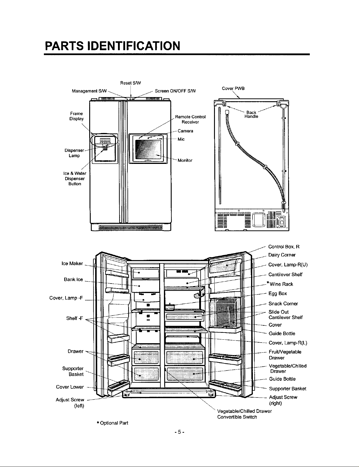
PARTS IDENTIFICATION
Manag
Frame
Display
Lamp
Ice &Water
Dispenser
Button
Banklce
Reset S/W
Cover PWB
RemoteControl
Receiver
Camera
Control Box, R
Dairy Corner
Cover, Lamp-R(U)
Cantilever Shelf
Cover,
Shelf-F
Supporter
Cover Lower
Adjust Screw
Basket
(left)
* Optional Part
Egg Box
Snack Comer
Slide Out
Cantilever Shelf
Cover
Guide Bottle
Cover, Lamp-R(L)
FruiUVegetable
Drawer
Drawer
Bottle
AdjustScrew
(right)
\\
Vegetable/Chilled Drawer
Convertible Switch
.5-
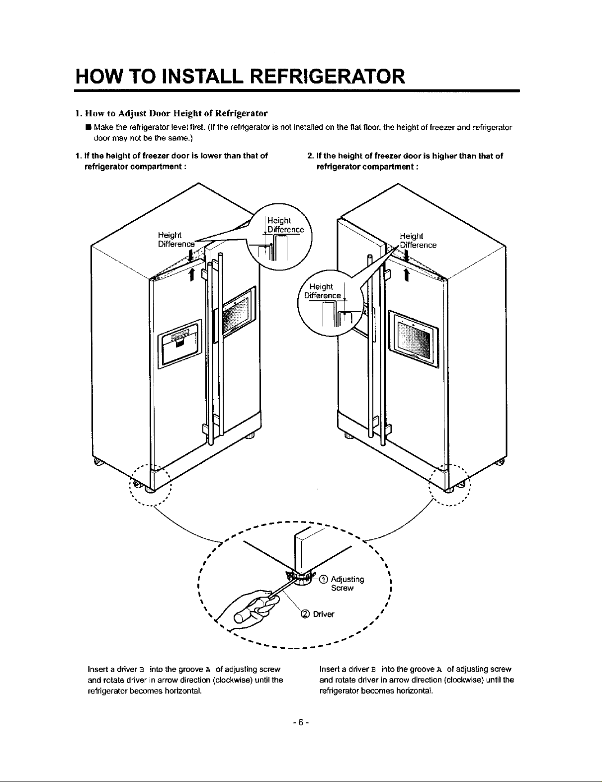
HOW TO INSTALL REFRIGERATOR
1. How to Adjust Door Height of Refrigerator
• Make the refrigerator level first. (ff the refrigerator is not installed on the fiat floor, the height of freezer and refrigerator
door may not be the same.)
1. If the height of freezer door is lower than that of
refrigerator compartment :
2. If the height of freezer door is higher than that of
refrigerator compartment :
Insert a driver B into the groove A of edjusting screw
and rotate driver in arrow direction (clockwise) until the
refrigerator becomes horizontal.
Insert a ddver B into the groove A of adjusting screw
and rotate driver in arrow direction (clockwise) until the
refrigerator becomes horizontal.
-6-
HOW TO INSTALL REFRIGERATOR
2. How to Install Water Pipe
• Before Installation
t. The icemaker requires the water pressure of 1.5 -
8.5kgf/cm 2. (It is acceptable if city water fills a cup of
180cc with water for 10 seconds)
2. Install booster pump where the city water pressure is
below 1.5kgf/cr_- for normal operation of water and ice
dispenser.
3. The total length of water pipe shall be less than 12rn. Do
not bend the pipe at right angle. If the length is more
than 12m. there will be troubles on water supply due to
water pressure drop.
4. Please install water pipe where there is no heat around.
5. Be sure that the filter does not sterilize.
6. The life span of water filter depends on the use
conditions. But the filter is generally replaced in every
six months. Install filter where replacement can be easily
performed,
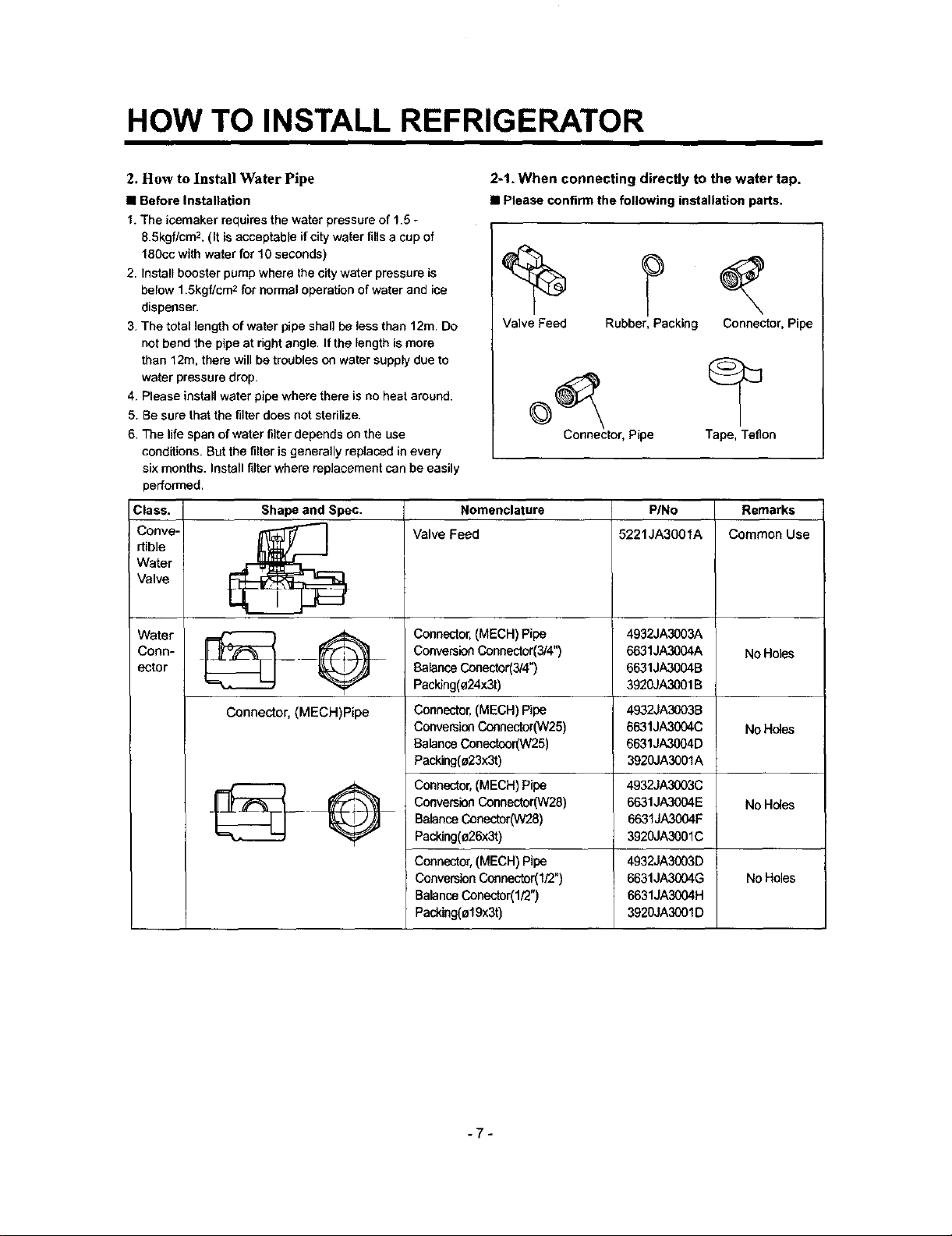
Class. Shape and Spec. Nomenclature PINo Remarks
Conve- _.[_"_ Valve Feed 5221JA3001A Common Use
rtible
Water
Valve
2-1. When connecting directly to the water tap.
• Please confirm the following installation parts.
Valve Feed Rubber, Packing Connector, Pipe
Connector, Pipe Tape, Teflon
Connector,(MECH)Pipe
Conn- _____ 6631JA3004A No Holes
ector 6631JA3004B
Water _ Q 4932JA3003A
Connector, (MECH)Pipe
ConversionConnector(3/4")
BalanceConector(3/4")
Packing(o24x3t)
Connector,(MECH) Pipe
ConversionCeenector(W25)
BalanceConectcor(W25)
Packing(a23x3t)
Connector,(MECH)Pipe
ConversionConnector(W28)
BalanceConector(W28)
Packing(e26x3t)
Connector,(MECH)Pipe
ConversionConnector(I/2")
BalanceConector(1/2")
Packing(ol9x3t)
3920JA3001 B
4932JA3003B
6631JA3004C
No Holes
6631JA3004D
3920JA3001A
4932JA3(X)3C
6631JA3004E No Holes
6631JA3004F
3920JA3001C
4932JA3003D
6631JA3004G
No Holes
6631JA3004H
3920JA3001D
-7-
HOW TO INSTALL REFRIGERATOR
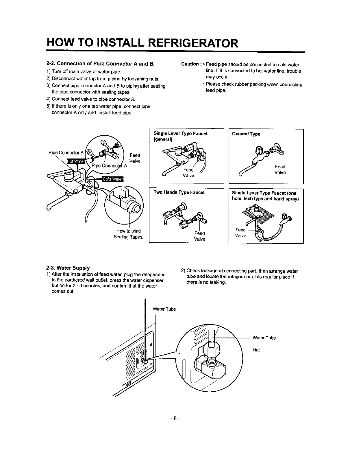
2-2. Connection of Pipe Connector A and B.
1) Turn off main valve of water pipe.
2) Disconnect water tap from piping by loosening nuts.
3) Connect pipe connector A and B to piping alter sealing
the pipe connector with sealing tapes.
4) Connect feed valve to pipe connector A.
5) Ifthere isonly one tap water pipe, connect pipe
connector A only and install feed pipe.
Single Lever Type Faucet
(general)
Pipe Connector B Feed
\
A
Two Hands Type Faucet
How towind
SealingTapes.
Caution : oFeed pipe should be connected to cold water
line. If it is connected to hot water line, trouble
may occur.
• Please check rubber packing when connecting
feed pipe.
Gene_lType
Feed
Valve
Single LeverTypeFaucet(one
hole, techtypeand hand spray)
Feed
Valve
Valve
2-3. Water Supply
1) After the installation of feed water, plug the refrigerator
to the earthered wall outlet, press the water dispenser
button for 2 - 3 minutes, and confirm that the water
comes out.
2) Check leakage at connecting part, then arrange water
tube and locate the refrigerator at its regular place if
there is no leaking.
-8-
HOW TO INSTALL REFRIGERATOR
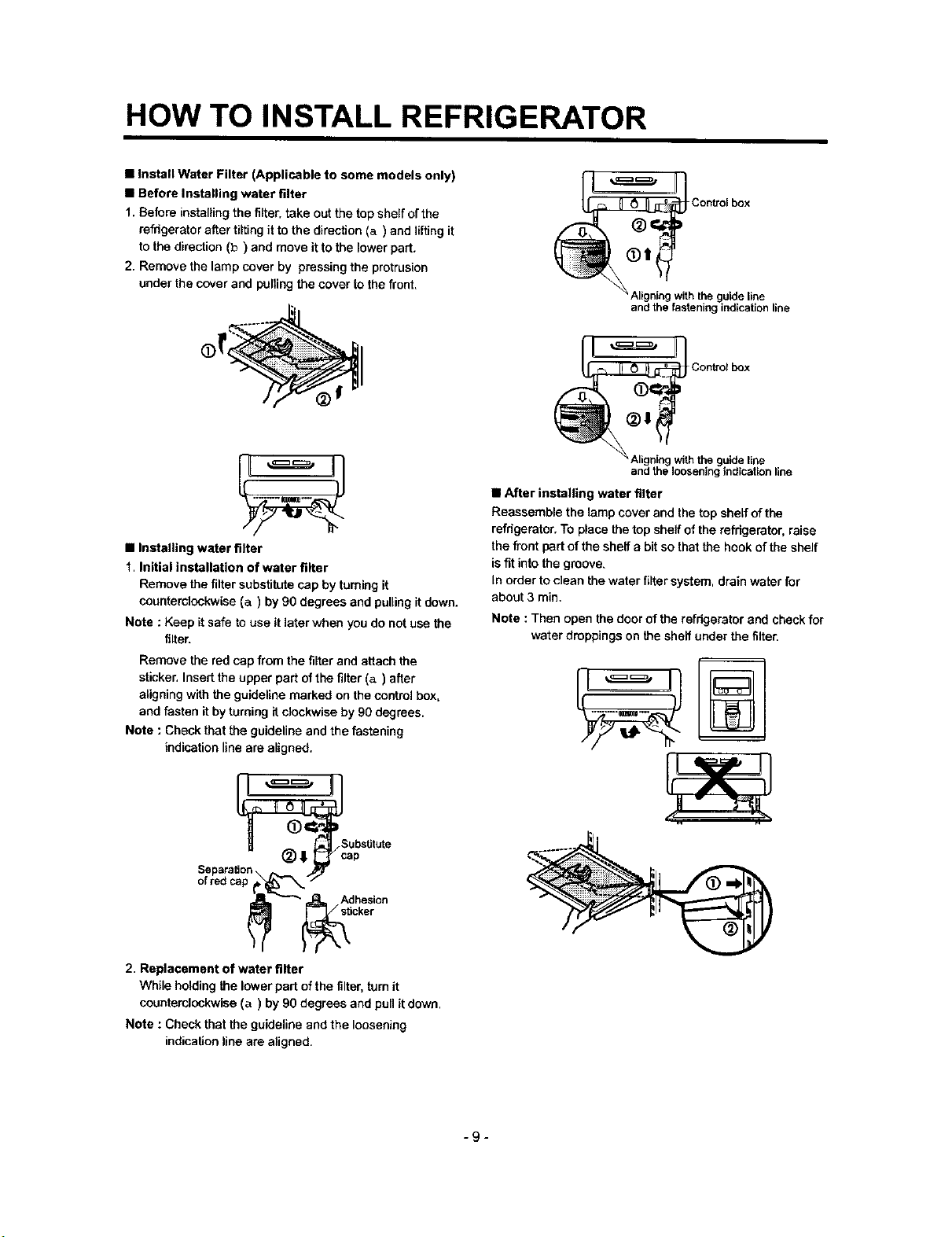
• Install Water Filter (Applicable to some models only)
• Before Installing water filter
1. Before installing the filter, take out the top shelf ofthe
refrigerator after tilting it to the direction (a) and lifting it
to the direction (b) and move it to the lower part.
2. Remove the lamp cover by pressing the protrusion
under the cover and pufiing the cover to the front.
O_i ;ontrolbox
• After installing water filter
Reassemble the lamp cover and the top shelf of the
refrigerator. To place the top sheff of the refrigerator, raise
• Installing water filter
1. Initial installation of water filter
Remove the filter substitute cap by turning it
counterclockwise (a) by 90 degrees and pulling it down.
Note : Keep it safe to use it later when you do not use the
filter.
Remove the red cap from the filter and attach the
sticker, Insert the upper part of the filter (a) after
aligning with the guideline marked on the control box,
and fasten it by turning it clockwise by 90 degrees.
Note : Check that the guideline and the fastening
indication line are aligned.
the front part of the shelf a bit so that the hook of the shelf
is fit into the groove.
In order to clean the water filter system, drain water for
about 3 min.
Note : Then open the door of the refrigerator and check for
water droppings on the shelf under the filter.
Control box
and the fastening indication line
guide line
JI
" " " the guide line
andthe loosening indication line
_ubstitute
_=_= Adhesion
_ _icker
2. Replacement of water filter
While holding the lower part of the filter, turn it
counterclockwise (a) by 90 degrees and pull it down.
Note : Check that the guideline and the loosening
indication line are aligned.
-9-
HOW TO INSTALL REFRIGERATOR
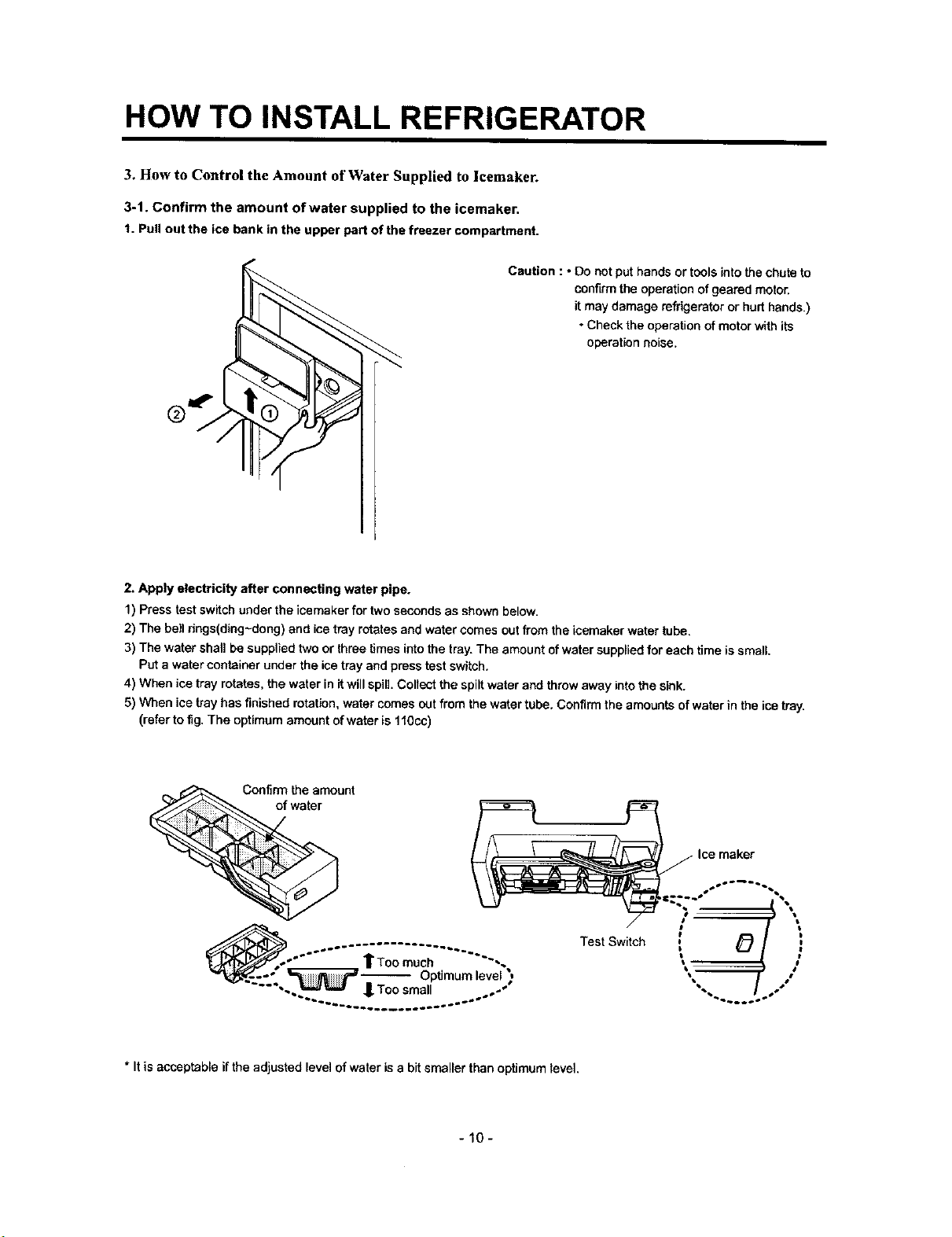
3. How to Control the Amount of Water Supplied to icemaker.
3-1. Confirm the amount of water supplied to the icemaker.
t. Pullout the ice bank in the upper pert of the freezer compartment.
Caution : * Do not put hands or tools into the chute to
confirm the operation of geared motor.
it may damage refrigerator or hurt hands.)
• Check the operation of motor with its
operation noise.
2. Apply electricity after connecting water pipe.
1) Press test switch under the icemaker for two seconds as shown below.
2) The bell rings(ding-dong) and ice tray rotates and water comes out from the icemaker water tube.
3) The water shall be supplied two or three times into the tray. The amount of water supplied for each time is small
Put a water container under the ice tray and press test switch.
4) When ice tray rotates, the water in it will spill. Collect the spilt water and throw away into the sink.
5) When ice tray has finished rotation, water comes out from the water tube. Confirm the amounts of water in the ice tray.
(refer to fig. The optimum amount of water is 110cc)
Confirm the amount
of water
Ice maker
Test Switch
i '
* It is acceptableifthe adjusted levelofwater isa bit smaller than optimumlevel.
-10-
HOW TO INSTALL REFRIGERATOR
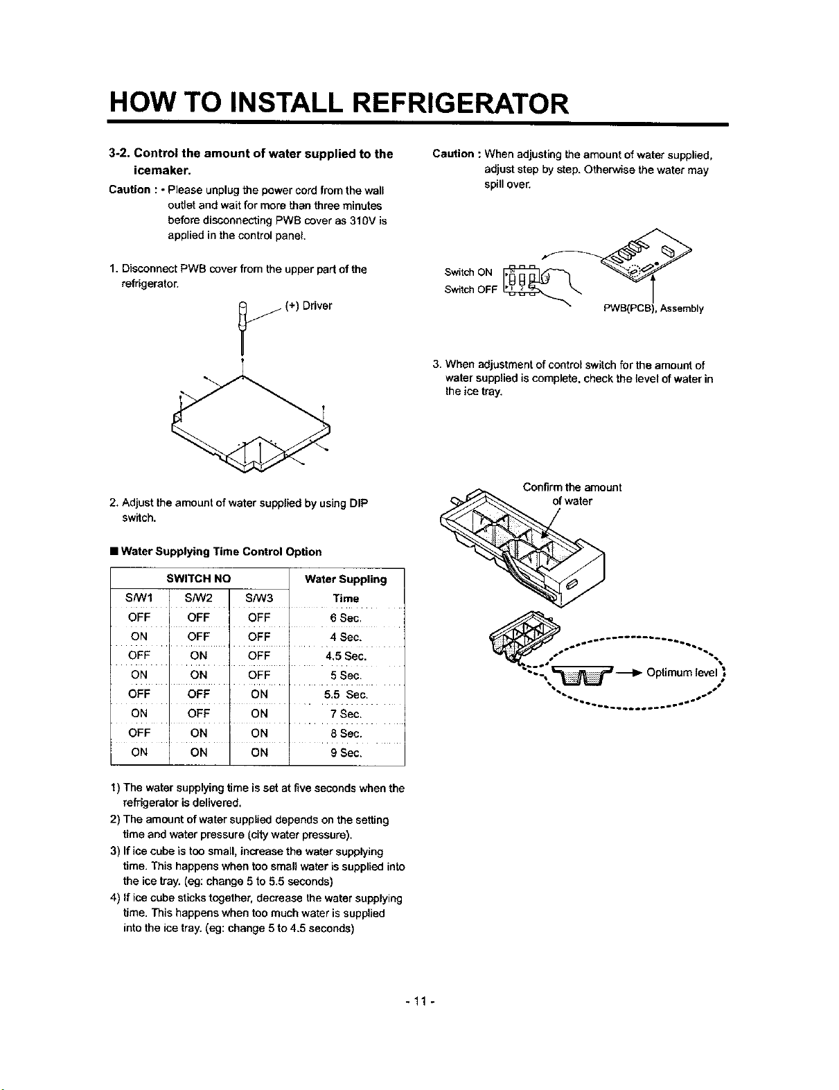
3-2. Control the amount of water supplied to the
icemaker.
Caution : • Please unplugthe powercordfrom thewall
outletand waitfor more than three minutes
before disconnectingPWS coveras 310V is
appliedin thecontrolpanel,
1. Disconnect PWB cover from the upper part of the
refrigerator.
j(+) Driver
2, Adjust the amountof water suppliedby usingDIP
switch.
• Water Supplying Time Control Option
Caution : When adjusting the amount of water supplied,
adjust step by step. Otherwise the water may
spill over.
Switch ON
Switch OFF
PWB(PCB), Assembly
3. When adjustment of control switch for the amount of
water supplied is complete, check the level of water in
the ice tray.
Confirm the amount
of water
SWITCH NO Water Suppling
S/W1 SNV2 S/W3 Time
OFF OFF OFF 6 Sec.
ON OFF OFF 4 Sec.
OFF ON OFF 4.5 Sec.
ON ON OFF 5 Sec.
OFF OFF ON 5.5 Sec.
ON OFF ON 7 Sec.
OFF .... ON ON ..... 8Sec.
ON ON ON g Sec.
1) The water supplying time is set at five seconds when the
refrigerator is delivered.
2) The amount of water supplied depends on the setting
time and water pressure (city water pressure).
3) If ice cube is too small, increase the water supplying
time. This happens when too small water is supplied into
the ice tray. (eg: change 5 to 5.5 seconds)
4) If ice cube sticks together, decrease the water supplying
time. This happens when too much water is supplied
into the ice tray. (eg: change 5 to 4.5 seconds)
Optimumle ,"
"'_b_ _o_ SS
-11 -

ICEMAKERANDDISPENSEROPERATIONPRINCIPLEANDREPAIRMETHOD
2°4. Ice Ejection Control Function
1. This is to eject ice from ice maker cube mould after ice making is completed.
2. if Hall IC signal is on within 3.6 seconds after ice ejection motor rotates in normal direction, it does not proceed ice
ejection but waits, If the ice bank is full ice ejection motor rotates in normal direction in every hour to check the condition
of ice bank. If the ice bank is not full, the water supply control starts after completion of ice ejection control. If the ice bank
is full, ice ejection motor rotates in reverse direction and sops under ice making or waiting conditions.
3. if ice bank isnot full, ice ejection starts. The cube mould tilts to the maximum and ice is separated from the mould and ice
checking lever raises.
4. Ice ejection motor stops for 1 second if Hall IC signal changes from OFF (low) to ON (high) after 3.6 seconds when ice
ejecSon motor rotates in normal direction. If there is no change in Hall IC signals within 1 minute after ice e}ection motor
operates, ice ejection motor stops as ice ejection motor or hall IC is out of order.
5. If ice ejection motor or Hall IC is abnormal, ice ejection motor rotates in normal direction to exercise initial operation. It
resets the ice maker if ice ejection motor or Halt IC is normal.
6. The mould stops for 1 second at maximum tilted conditions.
7. The mould returns to horizontal conditions as ice ejection motor rotates in reverse direction.
8. When the mould becomes horizontal, the cycle starts to repeat:
Water Supply ..* Ice Making * Ice Ejection .._Mould Returns to Horizontal
Maximum tilting
point
r Bank is
HALL IC
OUTPUT
SIGNALS
Bank is "_
HALL IC
OUTPUT
SIGNALS
I ICE CHECKING
o ' ' =-)'/'
i i i
i1_ I I i
OFF
ON
ICECHECKING LEVEL 30° i I
i p / I i t
t t t i i
-8' O" 10" 32' 41" 53" 68" 80'
Lock Ice making Ice Checking
(o_n_ i:,_nt)
2±1 sec = I
<Timing Chart During Ice Ejection>
• , r
, ,,
.... L .... J__J.
9:_3 sec
8+-3sac IL
I I
160" 170'
IceEjection Lock
L
- 22 -
ICEMAKERANDDISPENSEROPERATIONPRINCIPLEANDREPAIRMETHOD
2-5 Test Function
1. It is to force the operation during operation test, service, and cleaning. The test switch is mounted under the automatic
ice maker. The test function starts when the test switch is pressed for more than 0.5 second.
2. Test button does not work during ice ejection and water supply. It works when it is in the horizontal conditions. If mould is
full of ice during test function operation, ice ejection control and water supply control do not work.
3. When test switch is pressed for more than 0.5 second in the horizontal conditions, ice ejection starts irrespect of the
mould conditions. Water shall be splashed it test switch is pressed before the water in the mould freezes. Water shall be
supplied while the mould returns to the horizontal conditions after ice ejection. Therefore the problems of ice ejection,
returning to the horizontal conditions, and water supply can be checked by test switch. When test function performs
normally, buzzer sounds and water supply shall carry out. Check it for repair if buzzer does not sound.
4. When water supply is completed, the cycle operates normally as follows: Ice making • Ice ejection • Returning to
horizontal conditions , Water supply
5. Remove ice from the ice maker cube mould and press test switch when ice maker cube mould isfull of ice as ice ejection
and water supply control de not work when cube mould is full of ice.
2-6. Other functions relating to freezer compartment door opening
1, When freezer door is open, ice dispenser steps in order to reduce noise and ice drop.
2. When freezer door is open during ice ejection and cube mould returning to horizontal condition, ice ejection and cube
mould level return proceed.
3. When freezer door is open, geared motor and cube ice solenoid immediately stop and duct door solenoid stops after 5
seconds.
4. Water dispenser stops in order to protect water drop when freezer door is open.
5. Test function operates normally irrespect of refogearator cempadment door opening.
- 23 -
ICEMAKERANDDISPENSEROPERATIONPRINCIPLEANDREPAIRMETHOD
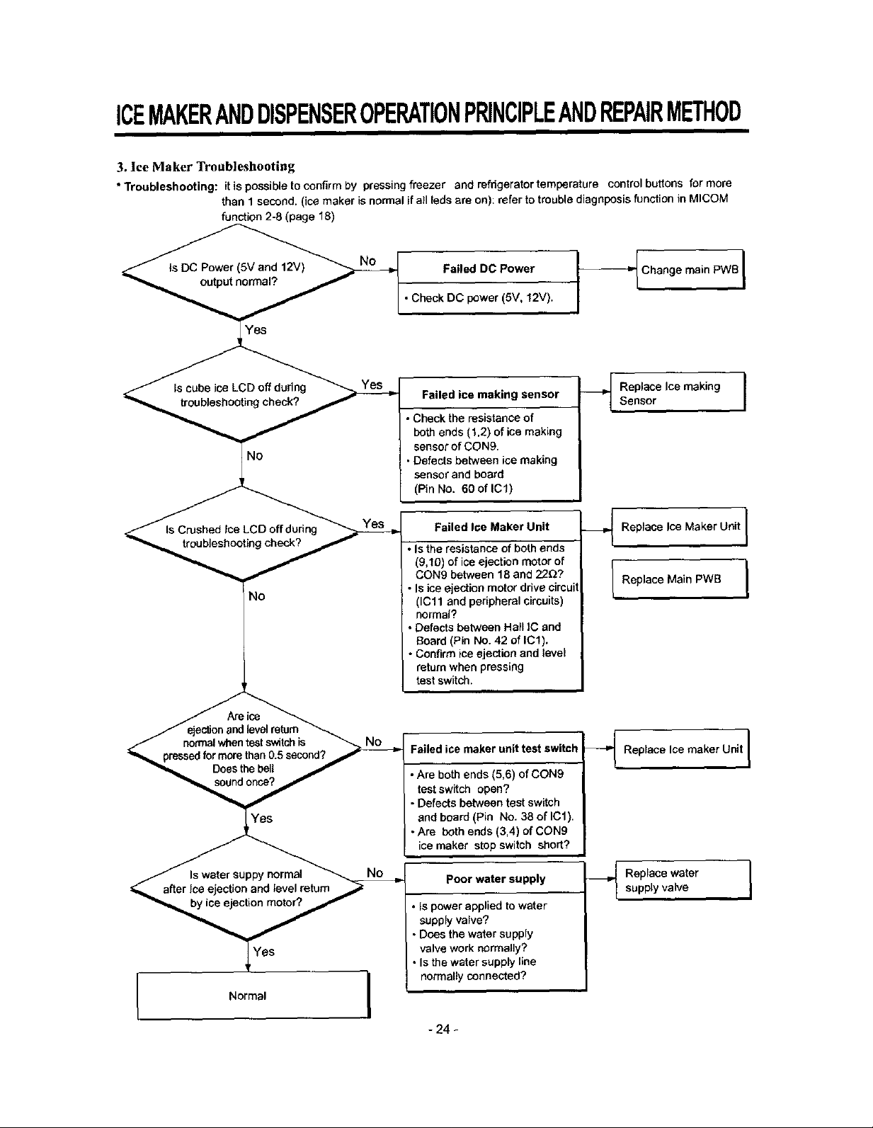
3. Ice Maker Troubleshooting
• Troubleshooting: itis possibletoconfirmby pressingfreezer and refrigerator temperature controlbuttons for more
than 1second.(icemaker is normalifall [edeare on): referto troublediagnposisfunction in MICOM
function 2-8 (page 18)
Failed DC Power
•Check DC power (5V, 12V).
Failed ice making sensor
• Check the resistance of
both ends (1,2) of ice making
sensor of CON9.
• Defects between ice making
sensor and board
(Pin No. 60oflCl)
Failed Ioe Maker Unit
• Isthe resistance of both ends
(9,10) of ice ejection motor of
CON9 between 18 and 22D?
No
r
• Is ice ejection motor drive circuit
(ICll and peripheral circuits)
normal?
• Defects between Hall IC and
Board (Pin No. 42 of IC1).
• Confirm ice ejection and level
return when pressing
test switch.
_ Chang e main PWB
Replace Ice making ]
Sensor
_._ Replace Ice Maker Unit [
I Replace Main PWB I
/ ejesb_nand level return
/ normalwhen test switch is
"_ pressedfor mere than 0.5 second? /
Does the bell /
Normal
Failed ice maker unit test switch
• Are both ends (5,6) of CON9
test switch open?
• Defects between test switch
and board (Pin No. 38 of IC1).
• Are both ends (3,4) of CON9
ice maker stop switch short?
Poor water supply
• Is power applied to water
supply valve?
• Does the water supply
valve work normally?
• Is the water supply line
normally connected?
- 24 -
_ Replace Ice maker Unit I
Replacewatersupplyvalve I
ICEMAKERANDDISPENSEROPERATIONPRINCIPLEANDREPAIRMETHOD
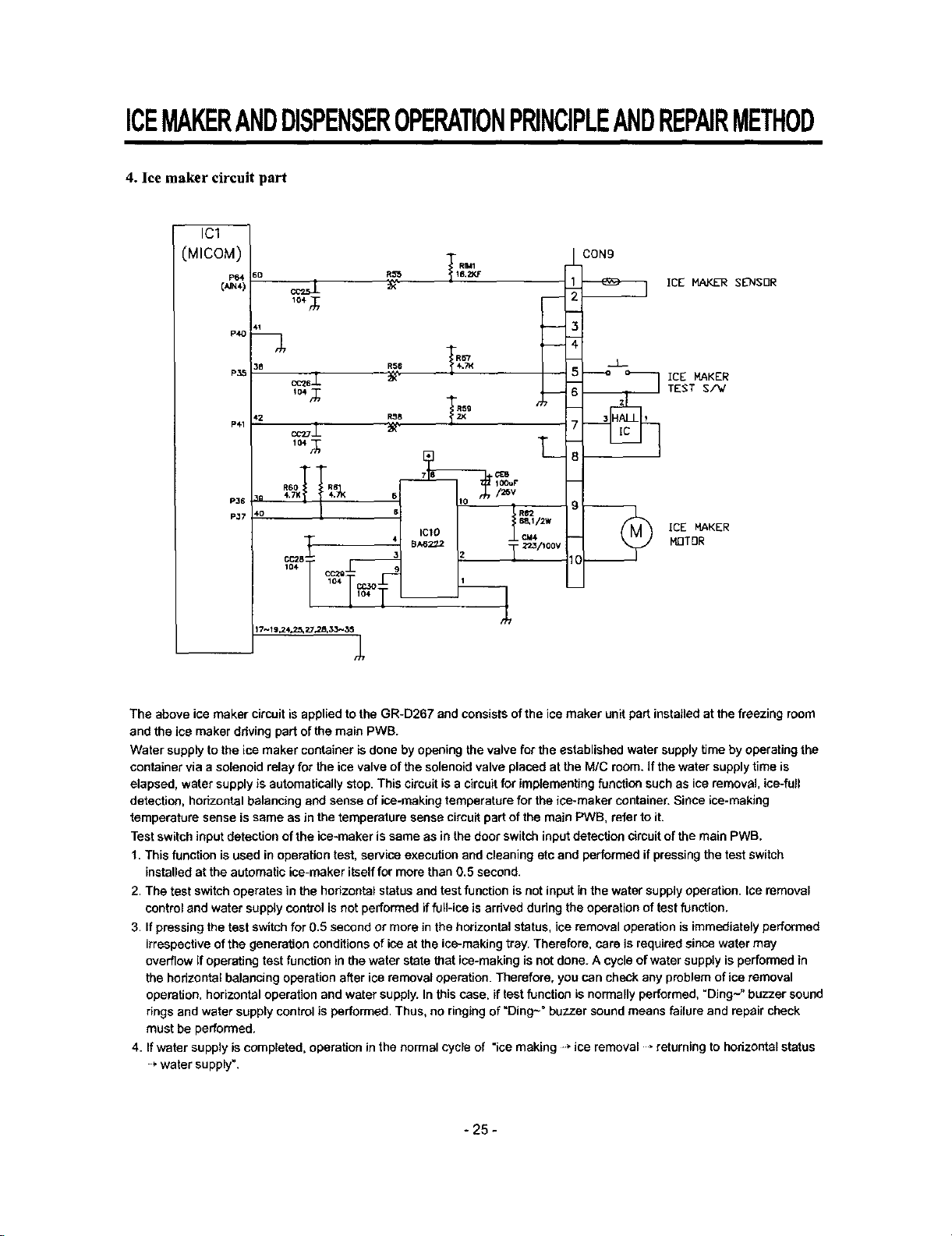
4. Ice maker circuit part
IC1
(MICOM)
P64
[,,,,_4)
P41
CON9
ICE MAKER
MOTOR
The above ice maker circuit is applied to the GR-D267 and consists of the ice maker unit pert installed at the freezing room
and the ice maker ddving part of the main PWB.
Water supply to the ice maker container is done by opening the valve for the established water supply time by operating the
container via a solenoid relay for the ice valve of the solenoid valve placed at the M/C room. If the water supply time is
elapsed, water supply is automatically stop. This circuit is a circuit for implementing function such as ice removal, ice-full
detection, horizontal balancing end sense of ice-making temperature for the ice*maker container. Since ice-making
temperature sense is same as Jnthe temperature sense circuit part of the main PWB, refer to it.
Test switch input detection of the ice-maker is same as in the door switch input detection circuit of the main PWB.
1. This function is used in operation test, service execution and cleaning etc and performed if pressing the test switch
installed at the automatic ice-maker itself for more than 0.5 second.
2. The test switch operates in the horizontal status and test function is not input in the water supply operation. Ice removal
control and water supply control is not performed if full-ice is arrived during the operation of test function.
3. If pressing the test switch for 0.5 second or more in the horizontal status, ice removal operation is immediately performed
irrespective of the generation conditions of ice at the ice*making tray. Therefore, care is required since water may
overflow if operating test function in the water state that ice-making is not done. A cycle of water supply is performed in
the horizontal balancing operation after ice removal operation. Therefore, you can check any problem of ice removal
operation, horizontal operation and water supply. In this case. if test function is normally performed, "Ding~" buzzer sound
rings and water supply control is performed. Thus, no ringing of"Ding~" buzzer sound means failure and repair check
must be performed.
4. If water supply is completed, operation in the normal cycle of "ice making -_ ice removal , returning to hodzontst status
* water supply".
- 25 -
EXPLATION FOR MICOM CIRCUIT
1. Explanation for PWB circuit
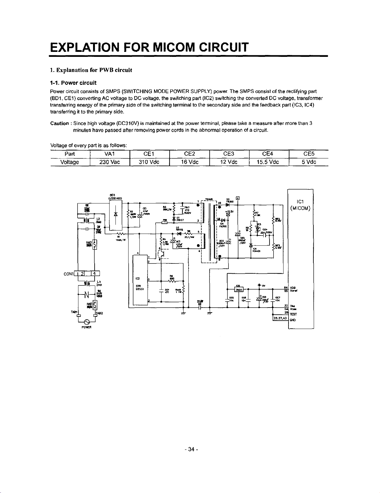
1-1. Power circuit
Power circuit consists of SMPS (SWITCHING MODE POWER SUPPLY) power. The SMPS consist of the rectifying part
(BDI, CE1) converting AC voltage to DC voltage, the switching part (IC2) switching the converted DC voltage, transformer
transferring energy of the primary side of the switching terminal to the secondary side and the feedback part (IC3. IC4)
transferring itto the primary side.
Caution : Since high voltage (DC310V) is maintained at the power terminal, please take a measure after more than 3
minutes have passed after removing power cords in the abnormal operation of a circuit.
Voltage of every part is as follows:
Voltage 230 Vac 310 Vdc 16 Vdc 12 Vdc 15.5 Vdc 5 Vdc
CONf
- 34 -
EXPLATION FOR MICOM CIRCUIT
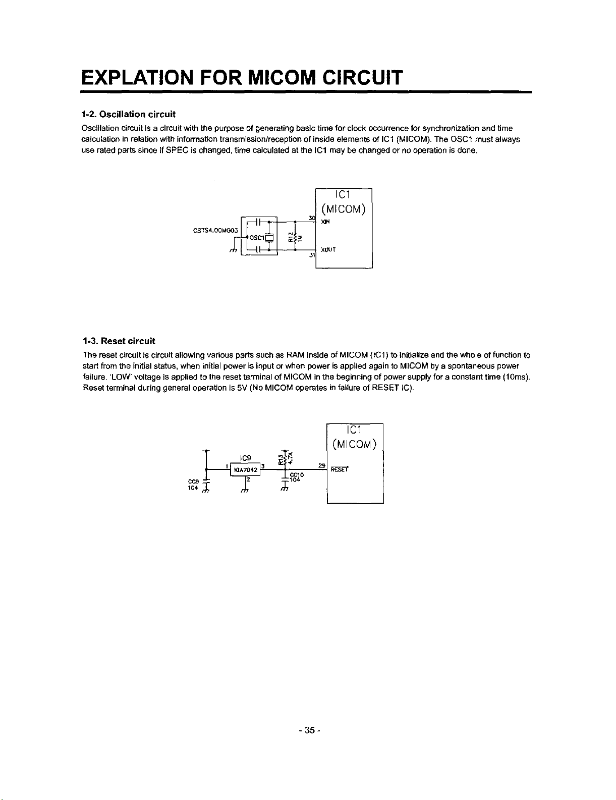
1-2. Oscillation circuit
Oscillation circuit is a circuit with the purpose of generating basic time for clock occurrence for synchronization and time
calculation in relation with information transmission/reception of inside elements of IC1 (MICOM). The OSCl must always
use rated parts since if SPEC is changed, time calculated at the IC1 may be changed or no operation is done.
ICl
(MICOM)
CS7S4 00MGO_
1-3. Reset circuit
The reset circuit is circuit allowing various parts such as RAM inside of MICOM (ICl) to initialize and the whole of function to
start from the initial status, when initial power is input or when power is applied again to MICOM by a spontaneous power
failure. 'LOW' voltage is applied to the reset terminal of MICOM in the beginning of power supply for a constant time (t Ores).
Reset terminal during general operation is 5V (No MICOM operates in failure of RESET IC).
xeur
IC1
(MICOM)
1 IC9 3 _ #
- 35 -
EXPLATION FOR MICOM CIRCUIT
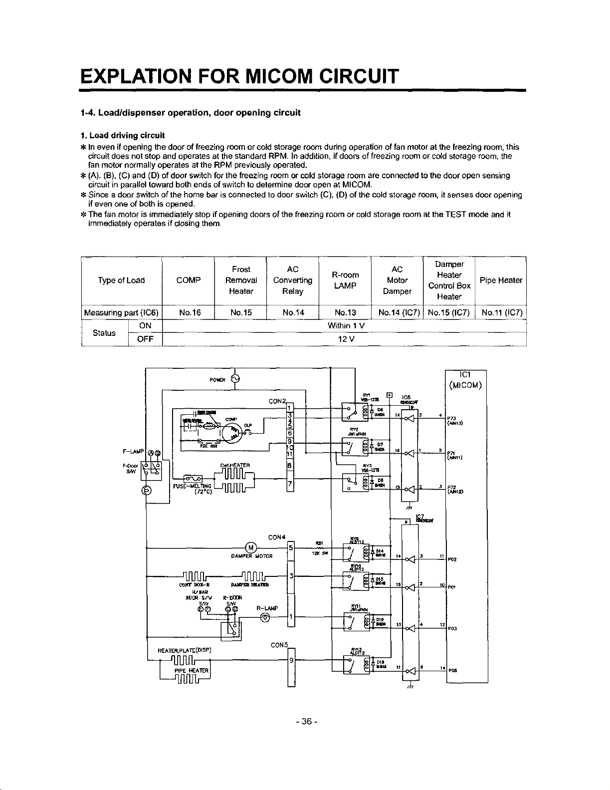
1-4. Load/dispenser operation, door opening circuit
1. Load driving circuit
In even if opening the door of freezing room or cold storage room during operation of fan motor at the freezing room, this
circuit does not stop and operates at the standard RPM. In addition, if doors of freezing room or cold storage room, the
fan motor normally operates at the RPM previously operated.
(A). (B), (C) and (D) of door switch for the freezing room or cold storage room are connected to the door open sensing
circuit in parallel toward both ends of switch to determine door open at MICOM.
_€Since a door switch of the home bar is connected to door switch (C), (D) of the cold storage room, it senses door opening
if even one of both is opened.
The fan motor is immediately stop if opening doors of the freezing room or cold storage room at the TEST mode and it
immediately operates if closing them.
Type of Load
vleasudng part (IC6)
Status OFF
F-LAkIP
Frost
COMP
Removal
Heater
No.16
No.15
_@
FUSE- M_oNC_ _ L._
)
AC
Converting
Relay
No.14
CON4
R-room
LAMP
No.13
Within 1 V
12V
AC
Motor
Damper
No.14 (IC7)
14 _ 4
IIS 1 2
Damper
Heater
Control Box
Heater
No.15 (IC7)
ICI
(MICOM)
=73
_Tt
i_11)
'_'112)
Pipe Heater
No.ll (IC7)
DAMP_ MO1"OR
_-_'1 _ _-I1 _ _Tl_t
ZDCR $/V R-DDQR
_g_2
PeTZ
DIS
P6_
P03
CON5
DIB
I
- 36 -
EXPLATION FOR MICOM CIRCUIT
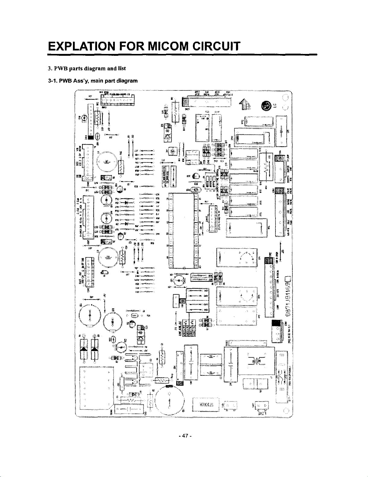
3. PWB parts diagram and list
3-1, PWB Ass'y, main part diagram
- 47 -
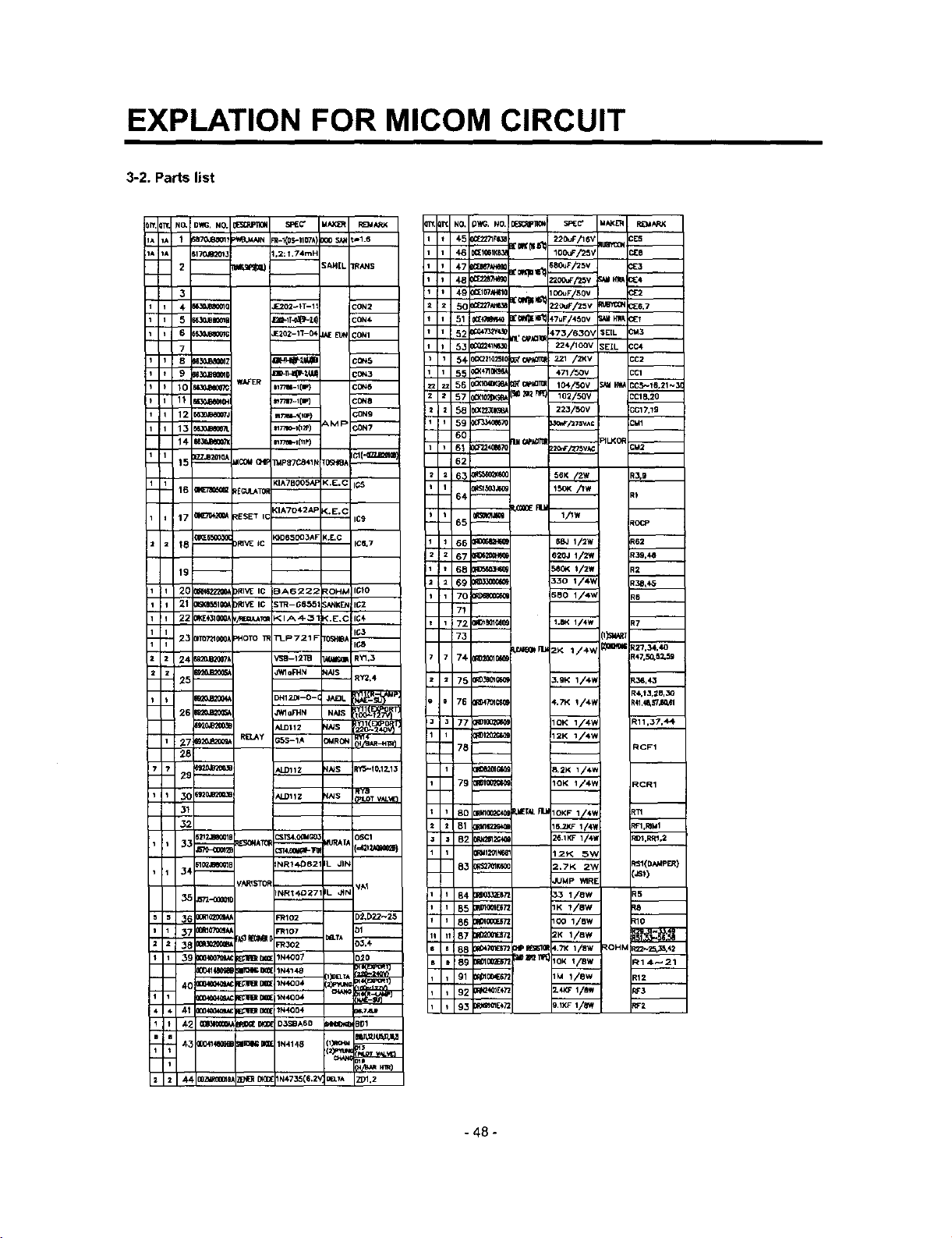
EXPLATION FOR MICOM CIRCUIT
3-2. Parts list
NO. DWG, NO. _ SREC' =IAX;I_ RE_ARK
1 ;BTOJBO01? _:_B.MNN R.I_tIOTA) _00 SA_ t_1.6
M70JOr2013 2: ?.74mH
2 _ _AH[L 1R,,LNS
3
_ Z3OJB_010 E202_IT-11 b'ON2
• 30JB_Cma [2nF+T_,_-lt) CON+
6- }$30jg_Q_G i£302-1T-0_ ._E_ CONI
7
_0 s63o,am=0 =_-_t4_ co_3
15 IZZJB2Ot__ _COU OtP B4pagCa41N r0S_9_ Icl{'0Z_sml
16 _ ,tg{;tJ_TOH
17 0(_R't_ _ESET IC IC9
18 -- 3RI_4_ +C IC_,7
WAFER mT_-Ilr) C0N6
_,_dB_07J mT_l-t(im} _C0N9
KIA7BOOSAP K+E.C
<IA7042AP <+E,(
19--
ITt NO+ O'h_, NO. _i_St_JF]_(_ SF4[C" dAKL'11 RI_4,t_K
+5 :[2271F¢3_ ;'_KOII_ 220uF/16V UE'R_ CE5
46 :I_tKLX_ 100uF/25V CIEB
48 _;'_o _ocuF/25v _1 _ c_4
_ 49 _t_lO t'Oeqllll_ oouFi50v C_2
z 5_ _t_._ !20uF/zsv _ CE6,7
51 0CE_R_ r_e_E_*_iF7uF/460v _tH_E?
_ :_241N8]_ 224,/1QOV ;EIL CC4
1 _4, 0C_21Q2510 _C_I]_ _21 /2KV CC2
_ 55 _<+____ +71/.',ov CCl
2 58 _(22.301(_ 223/50V ;C17,1g
1 59 O_P_670 3¢_'/_7swc CMI
6O
62
-- 64--
1 65 _ 1/IW tocP
66 _ SB_ 1/2W t6Z
z 67 _1t0_ 620J 1/2W 139.4_
+ 6B E 560(4 t/2w E2
6g _ 330 I/4W t38,43
1 70 m 5BO 1/4W le
73 [l_'_T
7 74 _1_01_ _47,50,5_59
75 m_m_ 3,9K 1/4W 136,4,3
_4,t3,21P,_
_0 '_21MB_D36: ALD11Z N_ RY_
3_
32
12_2.aooole CsTS4.OO_,___ MURAt^
tl0_,Jl_l_B =NRt_B2 IL_ JIN
_R_ST_
37 )ORlO_ 3(107 O1
_8 _ _/_/_ _R302 aa.TA D3,4
,*I11BItJ_l_; IN400+
4_ _ _ _ D3S_A6O _ BD1
,43 30m141_4_ ;II_'I_ IN4148 1_ mJ_li'l_'tt
_400_Ol_/ _ B_( N47_5(6.2' _._A ZD1,2
tF*ILOTVAL_E
osc1
J_ 77 R_I0_G_ 1OK 1/+V_ _11,37,4_
_'-78i--__ RCF1
79
80 Rm_ _T_ RtJ__ I_
B1 MI_O _ t+'1,mUl
B2 N2Sl_ 26.1KF 1/4_ _01.RRI,2
NI201k_ 12_<; _
_tK60 2._K 2"_, _:SI(DAMPER)
-- :.s_)
84 B_2ES,_ 33 1/8W _5
_5 R51g_4{57_ 1K 1/8w _8
86 _0too_z 1<:o 1/sw _10
It 87 _ 2K 1/8W
_188 ;4;_72 PIPRE_5]_ 4,7K 1/8W ROHM _'_2_42
91 1_1004E672 1M 1/OW R12
- 48 -
1OK 1/4_, _CR1
JUMp WlRE
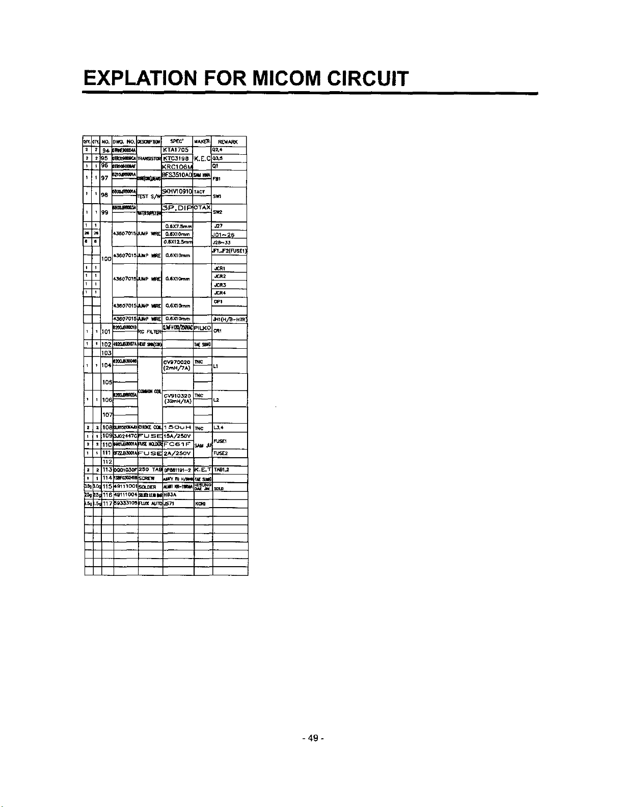
EXPLATION FOR MICOM CIRCUIT
94 _ ;<TAt 705 i0_4
95 _ _ <TC31S_ K.E,( 13.s
96 _ ,'RC106_ _--
97 _eeem/:o_=R,IZa pFS3510A( s._4_ _1
98 ooo.18_Bo_Jr_ST S,i_ ;KHV1091C TACt ;Vn
99 _--m_ _P,DIFOTAX =_r2
k380701_ = M_? _1 O,6XlOmm _-_26
100 )360701_ JUMp WIRE O,6XlOmm F_'JF'2(FUSE_1
k360707_ JUMp _ O-SXlOmm
1_60701= JUmp IA_ O.6XlO_m
_360701_ J_ v,_[ O.6XlOt_m I41{H/B-H]_
102 _o_1oo7_ I_!Is= ) T_
103
104 _ 3v97o02o TNC
0.6X7,Smrr J_7
0.6X12.Sm.1
JCRI
,_R4
OPt
!,_HiTA) -- .1
106 -- 12mH/t^) -- -_
10_ 3J024471 _USE 15A/250V
112
lt3 :_0103_ _50 TA_ 78811_1-2 _.E,T TAB1.1
11_ 4_111004 IIBI_ Hg3A
- 49 -
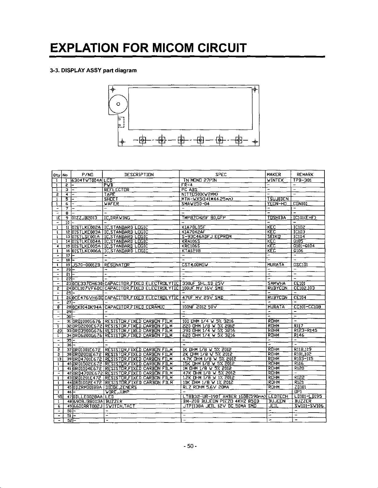
EXPLATION FOR MICOM CIRCUIT
3-3. DISPLAY ASSY part diagram
O_y NO P/NO
t 1 _304TWTOO4#
12
13
2 4
1
7
- 8
IE 9 )IZZJBBOI3
10
I 11 ]ISTLKEOOBA
I 12 IISTLKEOO3A
I 13 )ISTLSEOOIA
I 14 )ISTLKEOOAA
4 15 )ISTLKEOOGA
I 16 ]ISTLKEOOGA
17
- 18
I 19 J570-OOOIBB
20 -
21
22
- 23 DCE337CH630
2 24 OCEIO7VFGDC
- 25-
1 26 DCE476VHGDC
- 27 -
8 2B OCKIO4DK94A
29 -
30 -
- 310RDIOOOG676
1 320RDBBOOE672
Z3 330RB3900G676
l 340RD6200G676
35 -
- 36 -
2 370RD100IE672
2 3BORDBOOIE672
13 390RD4701EG72
I 4o ORDIGOBE672
1 410RBIOO4E672
- 4_ ORD4702E672
t 430RDIBOlE472
1 4A ORDlOO2E472
1 4_ OBZRMOO1BBA
I 4E-
95 47 ODLLEOO28AA
t 4t _908JBBOO3A
6 4_ _600RRTOO_J
5CI-
51-
5zI-
LED TN MONO 27PIN
PWB FR-4
REFLECTOR PC ABS
TAPE NITTOGOD(WBMM)
SHEET MTN-WX5(141mA4.25mm)
WAFER SHAW250-04
IC_BRAWING TNP87CHBIF BO_QFP
_IC_STANDARD LOGIC
lIE,STANDARD LOGIC
ICISTANDARB LOGIC
ICjSTANDARD LOGIC
ICISTANDARB LOGIC
IC_STANDARB LOGIC
RESONATOR CST4,0OMGW MURATA 0SC101
CAPACITORFIXED ELECTROLYTIC
CAPACITOR,FIXED ELECTROLYTIC
CAPACITOR_FIXEB ELECTROLYTIC
CAPACITDR_FIXED CERAMIC
RESISTOR_FIXEB CARBON FILM
RESISTOR_FIXED CARBON FILM
RESISTOR,FIXEB CARBON FILM
RESISTORIFIXED CARBON FILM
RESIBTORrFIXEB CARBON FILM
RESISTOR,FIXED CARBON FILM
RESISTOR,FIXED CARBON FILM
RESISTOR_FIXED CARBON FILM
RESISTOR,FIXED CARBON FILM
RESISTOR,FIXES CARBON FILM
RESISTOR,FIXED CARBON FILM
RESISTOR,FIXED CARBON FILM
DIODE_ZENERS
WIRErJUMP
LEg
BUZZER
SWITCH,TACT
DESCRIPTION SPEC
KIA78LO5F KEC ICI02
KIA7042AF KEC ICI03
S-93C46ABFJ EEPROM SEIKO ICt04
KRAI06S KEC QI05
KRCI06S KEC QIOI~QI04
KTAIBg8 KEC QI06
330UF SHL,SD 25V SAMWHA CEIOI
IOOUF NV IGV SMD RUBYCBN CEIO2rI03
47UF MV 25V SMD RUBYCDN CEI04
IODNF 2012 50V MURATA CCI01"CCIOB
100 OHM 114 W 5X 3216 _OHM
220 OHM I/8 W 5% 201B _OHN RII7
390 OHM I/4 W 5X 3216 !OHM RI23-R145
620 OHM 114 W 5% 3216 ROHM R146
IK OHM rib W 5% 2012 ROHM RIlB,]i9
2K OHM 118 W 5X 201B ROHM RIOI_IO2
4,7K OHM IIB W5% 2012 ROHM R103-115
15K OHM I/8 W 5% 201B RDHM R116
IM OHM I/8 V 5X 2012 _OHM RIB0
47K OHM i/8 V 5X 2012 RDHM -
I.BK OHM lib W i% 2012 ROHM RI22
IOK OHM 11B W IX 201_ ROHM R121
RLZ ROHM 5.6V 20MA ROHM ZBI01
.- - OPt
iLTBB32-UR-lBOT AMBER IGOB(590nm) LEDTECH LDIOI-LDI95
OH-BOB BUJEON PIEZO 4KHZ B5BB BUJEON :BUZZER
JTPII38A JEIL 12V DG 50MA SMD JEIL SWIOI'SWI06
MAKER REMARK
WINTEK TPB-381
TSUJIBEN
YEON-HO CONIOI
TOSHIBA ICI01(E=F)
-50 -
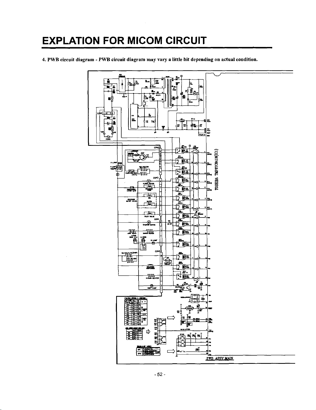
EXPLATION FOR MICOM CIRCUIT
4. PWB circuit diagram - PWB circuit diagram may vary a little bit depending on actual condition.
- 52 -
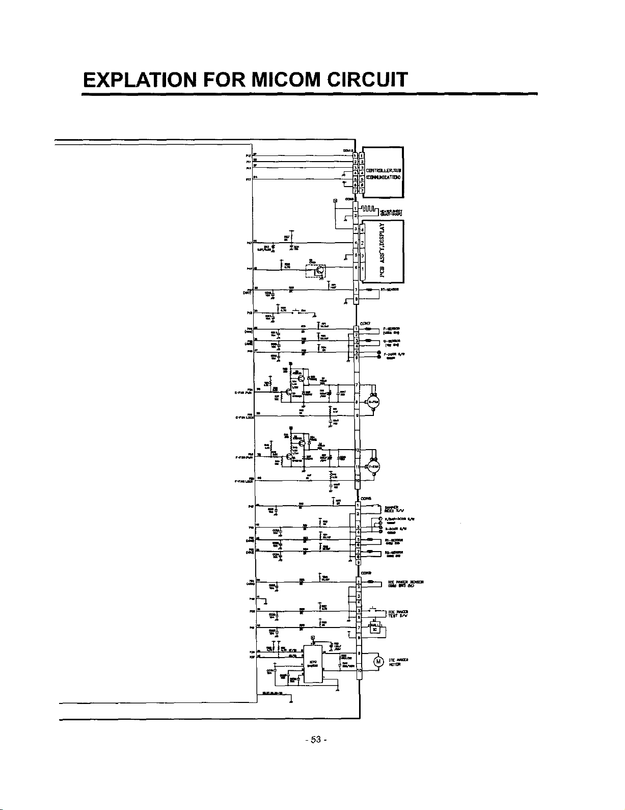
EXPLATION FOR MICOM CIRCUIT
)
T
T_
=-. T=
.. . T=,.
- 53 -
v
_ mm
E
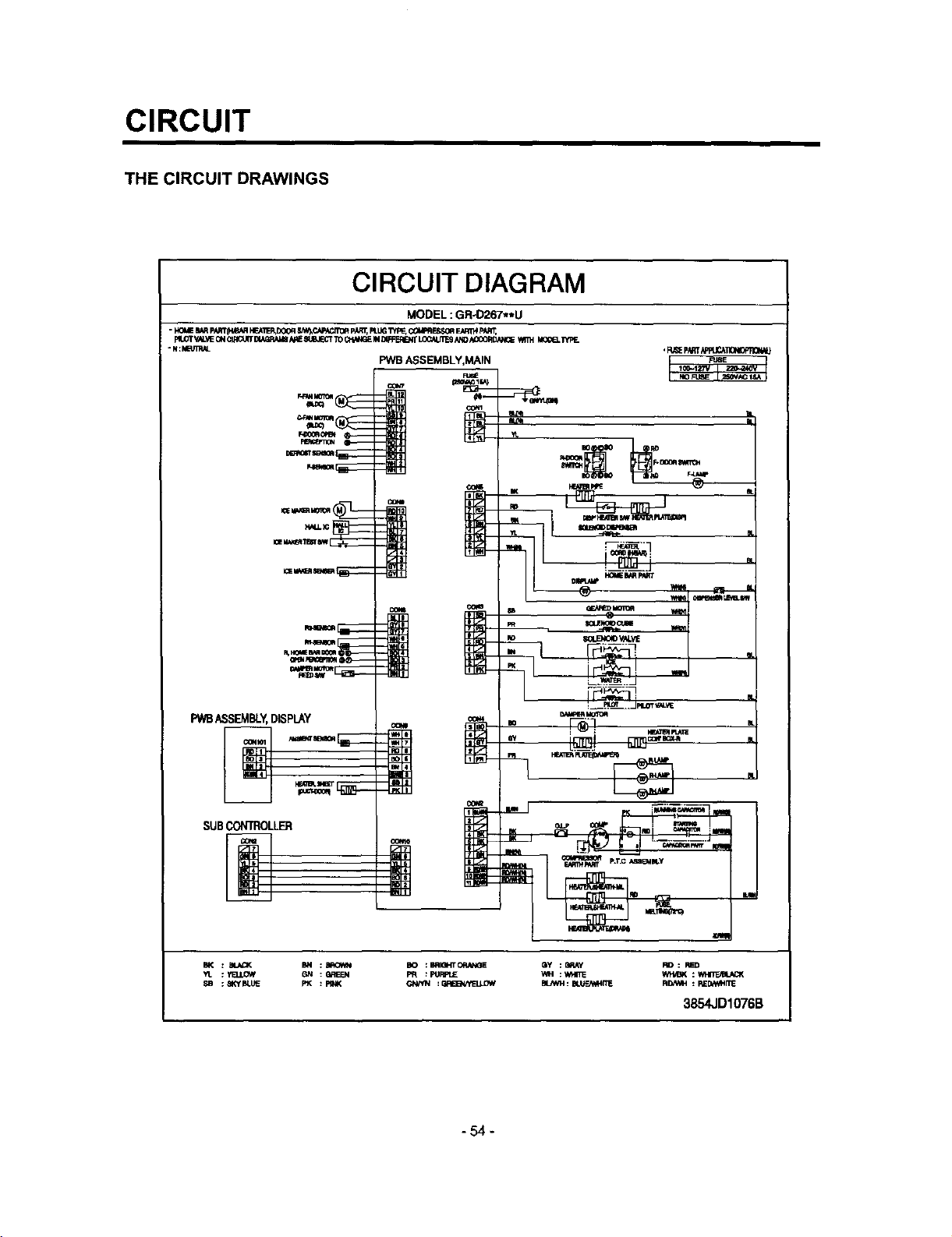
CIRCUIT
THE CIRCUIT DRAWINGS
CIRCUIT DIAGRAM
- I.!O_ e_/tpA_IW&_ FrcA_R,DOOFI_N_,CA=_.JT0_pAIT_,PI.UGWI=E,C_FIFJ_ E_qrtH pAR'_,
Ft.OTV_._EONQ;_C_IITDIA_qAt_&qESl_MEC'TTOCf,IiV_EIND_RIE_T _/_O ACCORDANQE_ M0_I_ 'i'YPF_
* N:HBrf_qL
PWB._SEMBLY,MAIN
MODEL : GR-D267**U
m_
PWBASSEMBLY,DISPLAY
SUBCONTROLLER
BK : _._'( M :BROW_ BO :BRIOpITOf_,_IE QY :E_Y RD: RED
Yr. : YELI.OW 13N : _qEEN PR : PUI=P.JE WH : wHr_ Wt'b_K : _
_B ;_O'I_UE P'_ :PINK GN/W_ :61R_/yLqJJ_W BlaW_:BI.UF2_ITE FIB/VAH:RE_Nt,.41TE
3854JD1076B
-54-
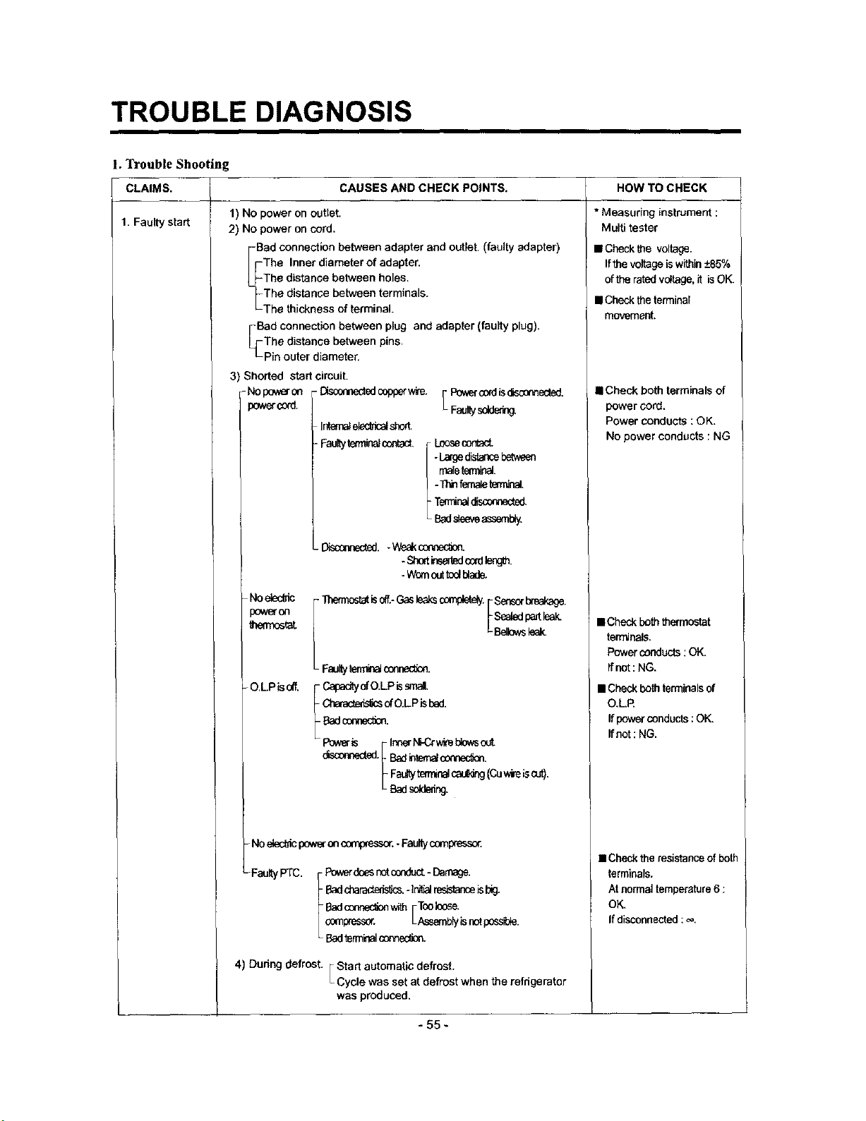
TROUBLE DIAGNOSIS
1.3¥ouble Shooting
CAUSES AND CHECK POINTS. HOW TO CHECKCLAIMS.
1. Faulty start
1) No power on outlet.
2) No power on cord.
Bad connection between adapter and outlet. (faulty adapter)
The Inner diameter of adapter.
The distance between holes.
The distanse between terminals.
The thickness of terminal.
Bad connection between plug and adapter (faulty plug).
The distance between pins,
Pie outer diameter,
3) Shorted start circuit.
Nopeweron -Disconnededcopperwire. [Pr_c_dgolsca'm_.
_wer_:_. _Fa_ys_
INemal_Ncat sh_,
-Faulty terminalcontact, [ Loosecont_t.
/ -La_d_,_r_ebe_v_
[ malete_ninal.
_ -Thin_role _rrr_nal.
Temlir_ olscer_ected.
L Badslseveasseml_y
._.. Weakconnec_
-Short_sat_dc0at_mgth.
- Wornout t_l btade.
- Noe_c_ic
)ower co
thennoatat
- O.L.PIS oil,
_tat is_.- Gas_aks completely.FSealedpartleak.
LBellowsleak.
I Sensorbreakage.
L FI_llty [e_ COt_(_Otl.
f CapadtyofO.LPissinai,
Characte_s_sofO.LP ls 13ed.
Badconne_on.
Po_ F InnertCCr wi_eblowsout
* Measuring instrument :
Multi tester
• Checkthe voltage.
Ifthevoitageiswithin+85%
ofthe ratedvoltage,it isOK.
• Checktheterminal
movement.
• Check both terminals of
power cord.
Power conducts : OK.
No power conducts : NG
• Checkboththermostat
terminals.
Powerconducts:OK.
Ifnot:NG.
• Check both terminals of
O.L.R
If power conducts ; OK,
ffnot: NG.
_ Fa_'tyterminalcau_,ing(Cuwireiscut).
L Badsoldering,
-NO electncpower on c_%o_.ssor.-Faultycompresso_
- FaultyPTC. Powerdoesnct(z_c_ - Damage.
-Badcharact_si_.-Ini_ reslstan_isbig.
Badcennec_nwith[TcoIoos_
compressor. Assemblyisnctpossble.
Badterminal_.
4) During defrost. FStart automaticdefrost.
L
Cycle wasset at defrost when the refrigerator
was produced,
- 55 -
• Check the resistance of both
terminals.
At normal temperature6 :
OK.
If disconnected : _.
 Loading...