

Page 1

Please observe the following safety precautions in order to
use safely and correctly the refrigerator and to prevent
accident and danger during repair.
1. Be care of an electric shock. Disconnect power cord
from wall outlet and wait for more than three minutes
before replacing PWB parts. Shut off the power
whenever replacing and repairing electric components.
2. When connecting power cord, please wait for more than
five minutes after power cord was disconnected from the
wall outlet.
3. Please check if the power plug is pressed down by the
refrigerator against the wall. If the power plug was
damaged, it may cause fire or electric shock.
4. If the wall outlet is over loaded, it may cause fire. Please
use its own individual electrical outlet for the refrigerator.
5. Please make sure the outlet is properly earthed,
particularly in wet or damp area.
6. Use standard electrical components when replacing
them.
7. Make sure the hook is correctly engaged.
Remove dust and foreign materials from the housing
and connecting parts.
8. Do not fray, damage, machine, heavily bend, pull out,
or twist the power cord.
9. Please check the evidence of moisture intrusion in the
electrical components. Replace the parts or mask it
with insulation tapes if moisture intrusion was
confirmed.
10. Do not touch the icemaker with hands or tools to
confirm the operation of geared motor.
11. Do not let the customers repair, disassemble, and
reconstruct the refrigerator for themselves. It may
cause accident, electric shock, or fire.
12. Do not store flammable materials such as ether,
benzene, alcohol, chemicals, gas, or medicine in the
refrigerator.
13. Do not put flower vase, cup, cosmetics, chemicals,
etc., or container with full of water on the top of the
refrigerator.
14. Do not put glass bottles with full of water into the
freezer. The contents shall freeze and break the glass
bottles.
15. When you scrap the refrigerator, please disconnect the
door gasket first and scrap it where children are not
accessible.
WARNINGS AND PRECAUTIONS FOR SAFETY
- 3 -
Page 2

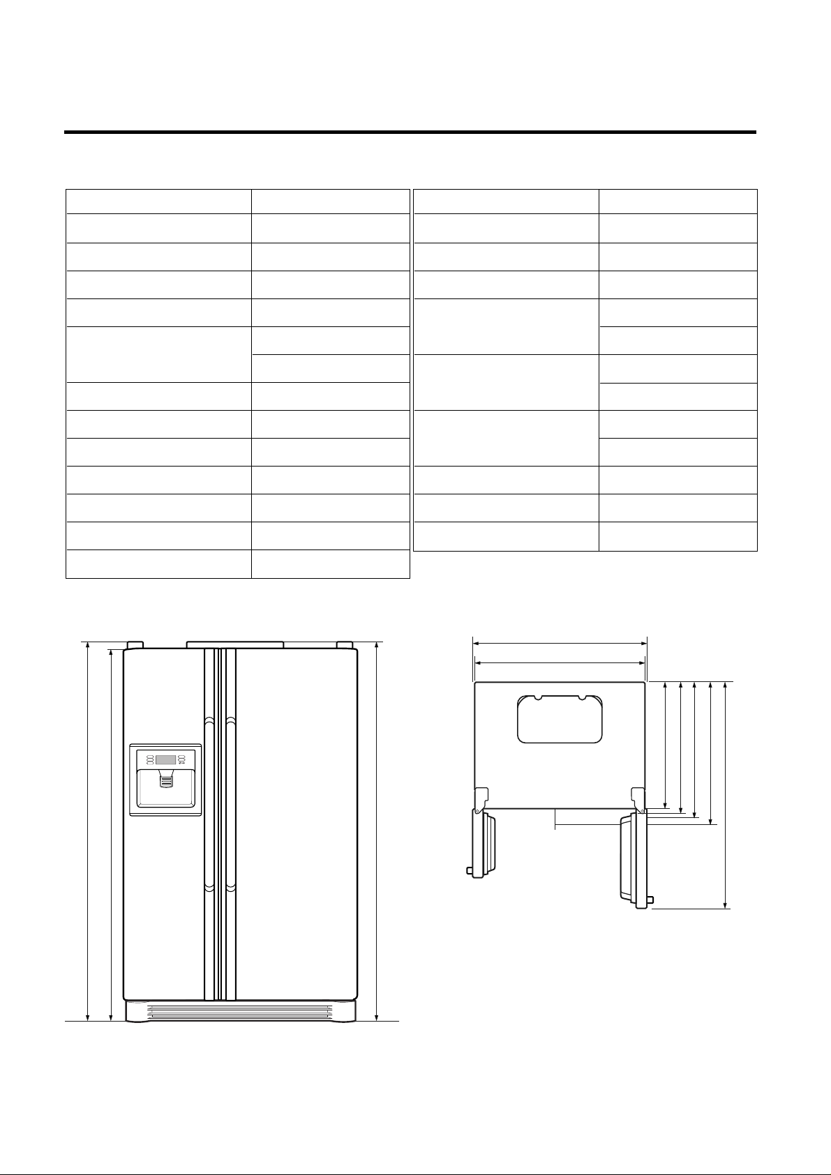
SPECIFICATIONS
- 6 -
ITEMS SPECIFICATIONS
DIMENSIONS (mm) 890(W)X840(D)X1750(H)
NET WEIGHT (kg) 125
COOLING SYSTEM Fan Cooling
TEMPERATURE CONTROL Micom Control
DEFROSTING SYSTEM Full Automatic
Heater Defrost
INSULATION Cyclo-Pentane
COMPRESSOR P.T.C. Starting Type
EVAPORATOR Fin Tube Type
CONDENSER Wire Condenser
REFRIGERANT R134a (185g)
LUBRICATING OIL FREOL @15G (320 cc)
DRIER 1Ø0.83
ITEMS SPECIFICATIONS
CAPILLARY TUBE MOLECULAR SIEVE XH-7
FIRST DEFROST 4 - 5 Hours
DEFROST CYCLE 13 - 15 Hours
DEFROSTING DEVICE Heater, Sheath
Heater, L-Cord
ANTI SWEAT HEATER Dispenser Duct Door Heater
Dispenser Heater
ANTI-FREEZING HEATER Water Tank Heater
Damper Heater
FREEZER LAMP 40W (1 EA)
REFRIGERATOR LAMP 40W (1 EA)
DISPENSER LAMP 15W (1 EA)
<Front View> <Plane View>
3. Ref No. : GR-L247
948
890
1750
1720
685
745
796
840
1218.5
1750
Page 3
SPECIFICATIONS
- 7 -
ITEMS SPECIFICATIONS
DIMENSIONS (mm) 890(W)X755(D)X1750(H)
NET WEIGHT (kg) 120
COOLING SYSTEM Fan Cooling
TEMPERATURE CONTROL Micom Control
DEFROSTING SYSTEM Full Automatic
Heater Defrost
INSULATION Cyclo-Pentane
COMPRESSOR P.T.C. Starting Type
EVAPORATOR Fin Tube Type
CONDENSER Wire Condenser
REFRIGERANT R134a (185g)
LUBRICATING OIL FREOL @15G (320 cc)
DRIER 1Ø0.83
ITEMS SPECIFICATIONS
CAPILLARY TUBE MOLECULAR SIEVE XH-7
FIRST DEFROST 4 - 5 Hours
DEFROST CYCLE 13 - 15 Hours
DEFROSTING DEVICE Heater, Sheath
Heater, L-Cord
ANTI SWEAT HEATER Dispenser Duct Door Heater
Dispenser Heater
ANTI-FREEZING HEATER Water Tank Heater
Damper Heater
FREEZER LAMP 40W (1 EA)
REFRIGERATOR LAMP 40W (1 EA)
DISPENSER LAMP 15W (1 EA)
<Front View> <Plane View>
4. Ref No. : GR-L207
948
890
1750
1720
600
660
711
755
1133.5
1750
Page 4
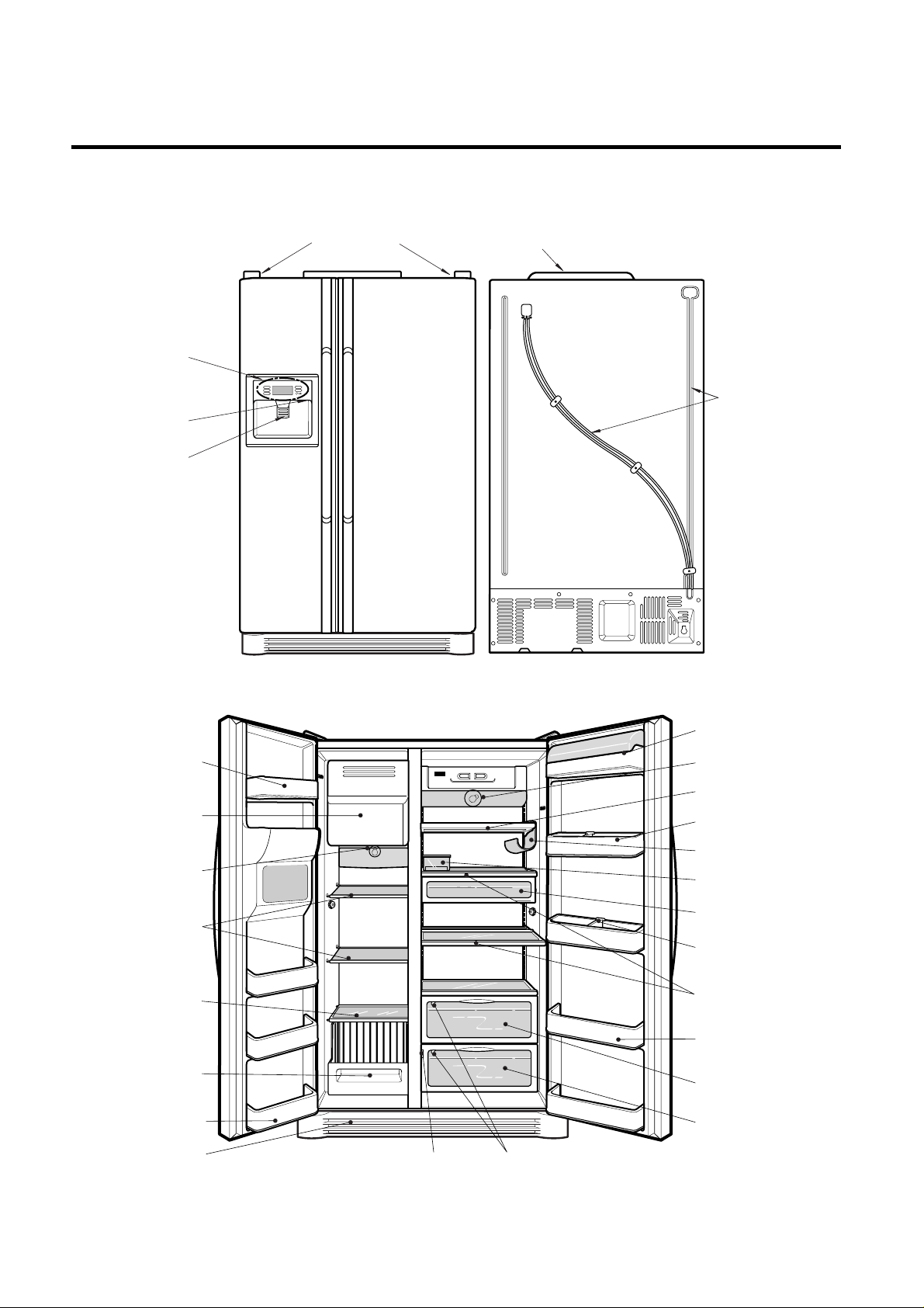
PARTS IDENTIFICATION
- 14 -
Cover PWB
Water Tube
Humidity Switch
Lamp
Shelf
Egg Box
Snack drawer
Vegetable drawer
Vegetable
drawer/Meat drawer
Door rack
Guide bottle
Shelf
Door rack
Wine holder (optional)
Lamp
Shelf
(Steel,
T/Glass)
Drawer
or Shelf
(optional)
Lower Cover
Milk product corner
Door rack
Drawer
Freezer
Compartment
Refrigerator
Compartment
Automatic
ice maker
Door rack
Conversion Switch
(Meats/Vegetables)
Cover Hinge
Frame Display
Dispenser Lamp
Ice & Water
Dispenser Button
3. Ref No. : GR-L247, GR-L207
Page 5
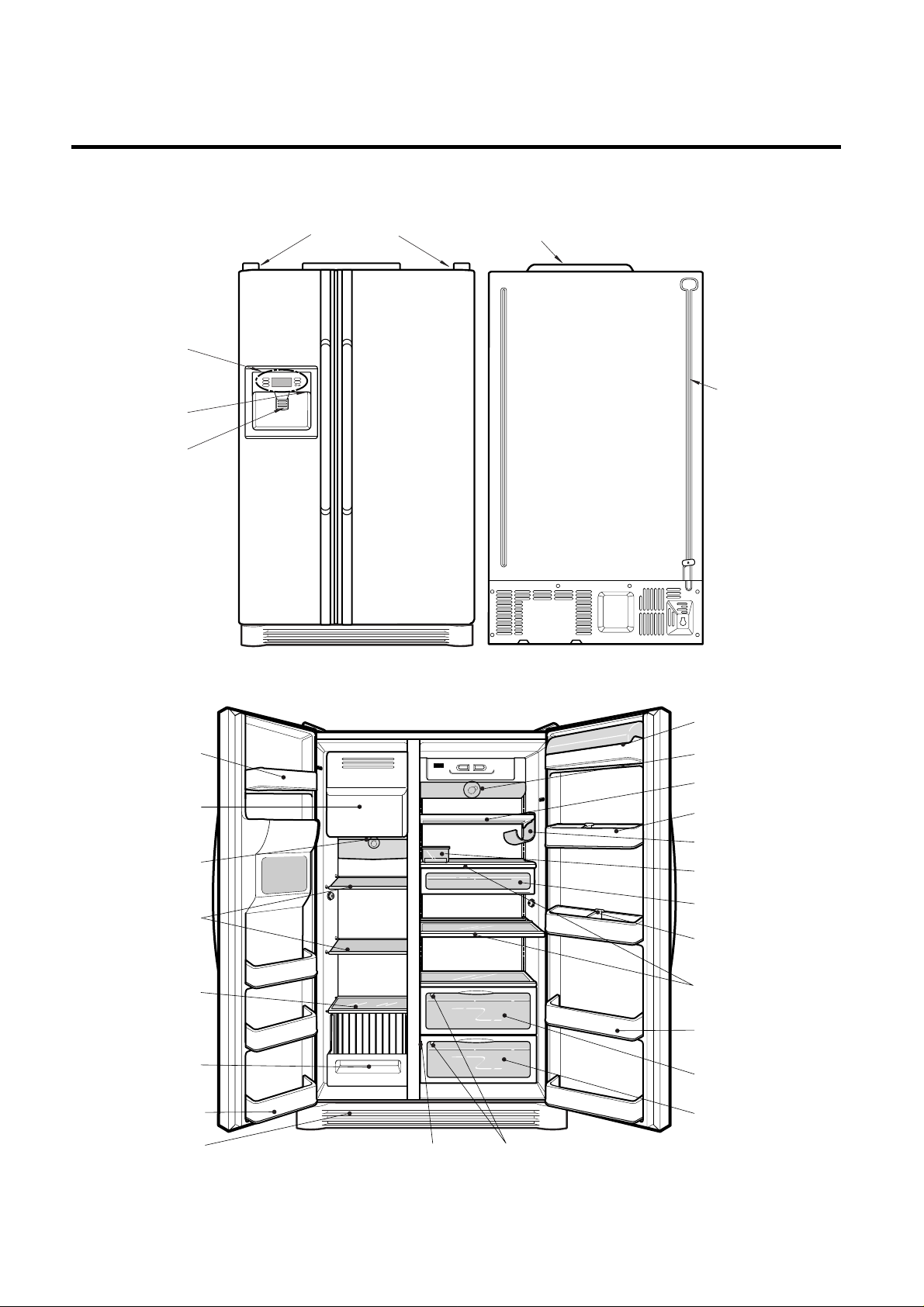
4. Ref No. : GR-L247, GR-L207
PARTS IDENTIFICATION
- 15 -
Conversion Switch
(Meats/Vegetables)
Cover PWB
Water Tube
Humidity Switch
Lamp
Shelf
Egg Box
Snack drawer
Vegetable drawer
Vegetable
drawer/Meat drawer
Door rack
Guide bottle
Shelf
Door rack
Wine holder (optional)
Lamp
Shelf
(Steel,
T/Glass)
Drawer
or Shelf
(optional)
Lower Cover
Milk product corner
Door rack
Drawer
Freezer
Compartment
Refrigerator
Compartment
Automatic
ice maker
Door rack
Cover Hinge
Frame Display
Dispenser Lamp
Ice & Water
Dispenser Button
Page 6
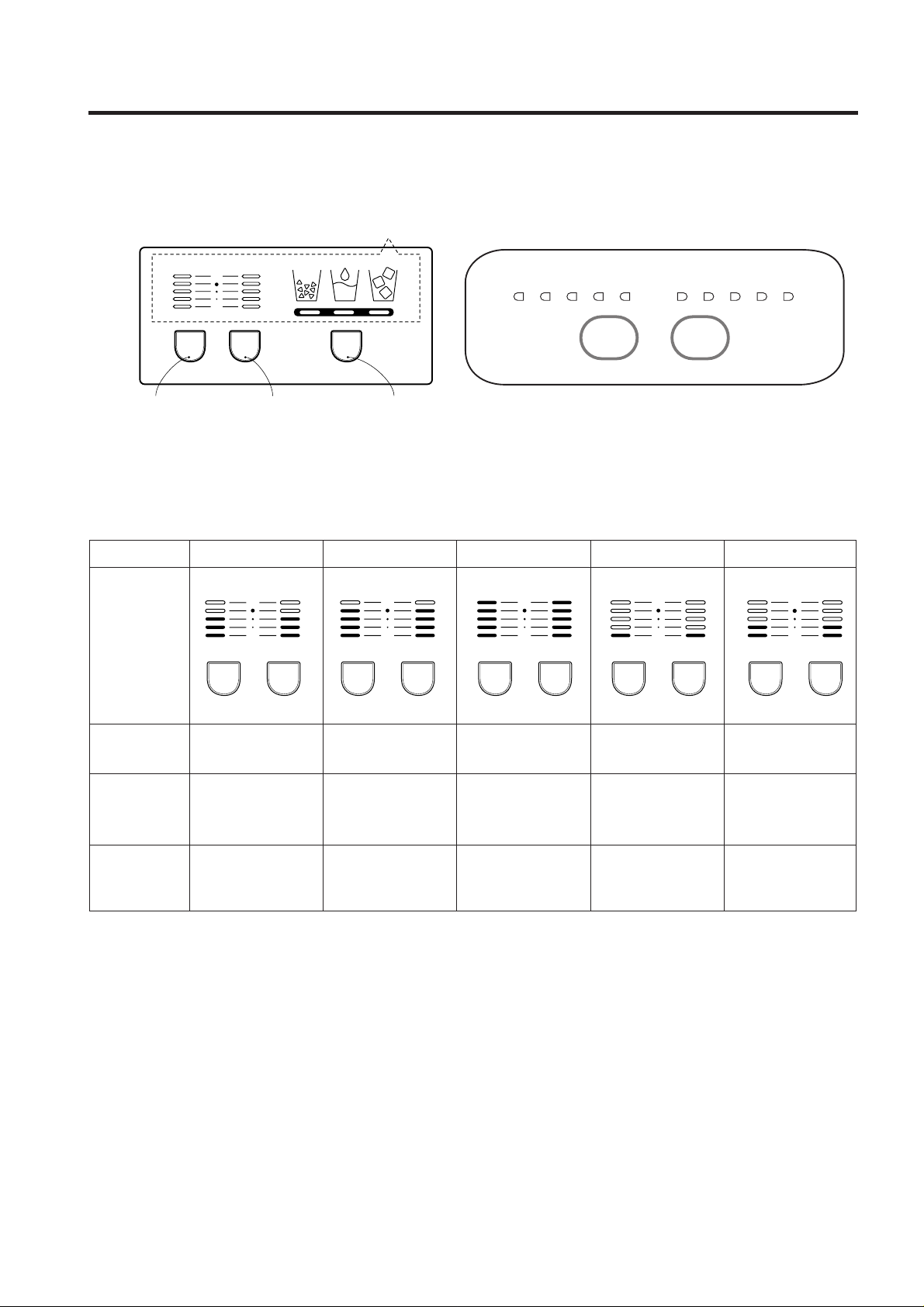
1. Monitor Panel
1-1. GR-P247, GR-P207, GR-L247, GR-L207 1-2. GR-C247, GR-C207, GR-B247, GR-B207
2. Description of Function
2-1. Funnction of Temperature Selection
* The temperature can vary ±3 °C depending on the load condition. *( ) : 127V/60Hz, 110~115V/60Hz, 115V/60Hz Rating ONLY.
*< > : TAIBEI
1. When power is initially applied or reapplied after power cut, “Medium” is automatically selected.
2. When the temperature selection switch in the freezer and refrigerator compartments is pressed, the light is on in the
following sequence:
"Medium"
➝ "Medium Max" ➝ "Max" ➝ "Min" ➝ "Medium Min" ➝ "Medium"
3. The temperature setting condition of freezer and refrigerator compartments shall not be indicate in the standard model
(GR-P247, GR-P207, GR-L247, GR-L207, GR-C247, GR-C207, GR-B247, GR-B207) when refrigerator or home bar
door is closed.
MICOM FUNCTION
- 25 -
FRZ
Temp
REF
Temp
SELECT
Max
Min
Function Monitor
Freezer compartment
temperature control Button
Refrigerator compartment
temperature control Button
Dispenser selection button
123455
Max MaxMin
4321
FRZ
Temp
REF
Temp
Division Power Initially On 1st Press 2nd Press 3th Press 4th Press
Change of
Indication Lamp
Temperature
Control
Medium Medium Max Max Min Medium Min
Freezer -19 °C -22 °C -23 °C
-15 °C -17 °C
Control (-18 °C) (-20.5 °C) (-22 °C)
<-19 °C> <-20.5 °C> <-22 °C> <-16.5 °C> <-18 °C>
Refrigeration
3 °C 1.5 °C 0°C
6 °C
4.5 °C
Control (7 °C)
<2 °C> <1 °C> <0 °C> <4.5 °C> <3 °C>
FRZ
Temp
Max
Min
REF
Temp
FRZ
Temp
Max
Min
REF
Temp
FRZ
Temp
Max
Min
REF
Temp
FRZ
Temp
Max
Min
REF
Temp
FRZ
Temp
Max
Min
REF
Temp
Page 7

2-2. Automatic ice maker
• The automatic ice maker can automatically make 8 pieces of ice cube at a time, 80 pieces a day. But these quantities may
be varied according to various conditions including how many times the refrigerator door opens and closes.
• Ice making stops when the ice storage bin is full.
• If you don’t want to use automatic ice-maker, change the ice-maker switch to ON-OFF.
If you want to use automatic ice-maker again, change the switch to OFF-ON.
NOTE : It is normal that a noise is produced when ice made is dropped into the ice storage bin.
2-3. When ice maker does not operate smoothly
Ice is lumped together
• When ice is lumped together, take the ice lumps out of the ice storage bin, break them into small pieces, and then place
them into the ice storage bin again.
• When the ice maker produces too small or lumped together ice, the amount of water supplied to the ice maker need to
adjusted. Contact the service center.
✻ If ice is not used frequently, it may lump together.
Power failure
• Ice may drop into the freezer compartment. Take the ice storage bin out and discard all the ice then dry it and place it
back. After the machine is powered again, crushed ice will be automatically selected.
The unit is newly installed
• It takes about 12 hours for a newly installed refrigerator to make ice in the freezer compartment.
MICOM FUNCTION
- 26 -
Page 8
2-4. Control of variable type of freezing room fan
1. To increase cooling speed and load response speed, MICOM variably controls freezing room fan motor at the high speed
of RPM and standard RPM.
2. MICOM only operates in the input of initial power or special freezing operation or load response operation for the high
speed of RPM and operates in the standard RPM in other general operation.
3. If opening doors of freezing / cold storage room or home bar while fan motor in the freezing room operates, the freezing
room fan motor normally operates (If being operated in the high speed of RPM, it converts operation to the standard
RPM). However, if opening doors of freezing room or home bar, the freezing room fan motor stops.
4. As for monitoring of BLDC fan motor error in the freezing room, MICOM immediately stops the fan motor by determining
that the BLDC fan motor is locked or poor if there would be position signal for more than 65 seconds at the BLDC motor.
Then it displays failure (refer to failure diagnosis function table) at the display part of refrigerator, performs re-operation in
the cycle of 30 minutes. If normal operation is performed, poor status is released and refrigerator returns to the initial
status (reset).
2-5. Control of M/C room fan motor
1. The M/C room fan motor performs ON/OFF control by linking with the COMP.
2. It controls at the single RPM without varying RPM.
3. Failure sensing method is same as in fan motor of freezing fan motor (refer to failure diagnosis function table for failure
display).
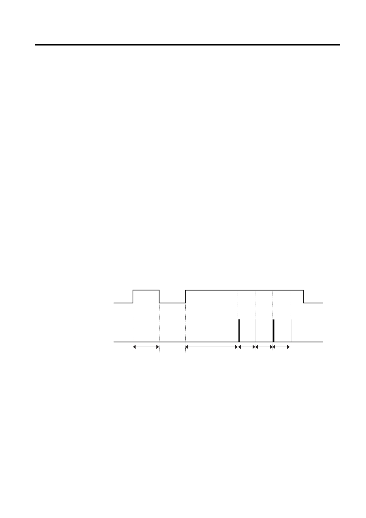
2-6. Door opening alarm
1. Buzzer generates alarm sound if doors are not closed even when more than a minute consecutively has passed with
doors of freezing / cold storage room or home bar opened.
2. Buzzer rings three times in the interval of 0.5 second after the first one-minute has passed after doors are opened and
then repeats three times of On/Off alarm in the cycle of every 30 seconds.
3. If all the doors of freezing / cold storage room or home bar are closed during door open alarm, alarm is immediately
released.
2-7. Ringing of button selection buzzer
1. If pressing the front display button, “Ding ~ “ sound rings.
2-8. Ringing of compulsory operation, compulsory frost removal buzzer
1. If pressing the test button in the main PCB, “Phi ~ “ sound rings.
2. In selecting compulsory operation, alarm sound is repeated and completed in the cycle of On for 0.2 second and Off for
1.8 second three times.
3. In selecting compulsory frost removal, alarm sound is repeated and completed in the cycle of On for 0.2 second , Off for
0.2 second, On for 0.2 second and Off for 1.4 second three times.
MICOM FUNCTION
- 27 -
Doors of freezing /
cold storage room
or home bar
BUZZER
Closing
Opening
Within
a minute
A minute
30
seconds30seconds30seconds
Opening
Closing Closing
3 Times 3 Times 3 Times 3 Times
Page 9
2-9. Frost removal function
1. Frost removal is performed whenever total operation time of compressor becomes 7 ~ 7.5 hour.
2. In providing initial power (or returning power failure), frost removal starts whenever total operation time of compressor
becomes 4 ~ 4.5 hour.
3. Frost removal is completed if temperature of a frost removal sensor becomes more than 5°C after starting frost removal.
Poor frost removal is not displaced if it does not arrive at 5°C even if two hours have passed after starting frost removal.
4. No removal is done if frost removal sensor becomes poor (snapping or short-circuit).
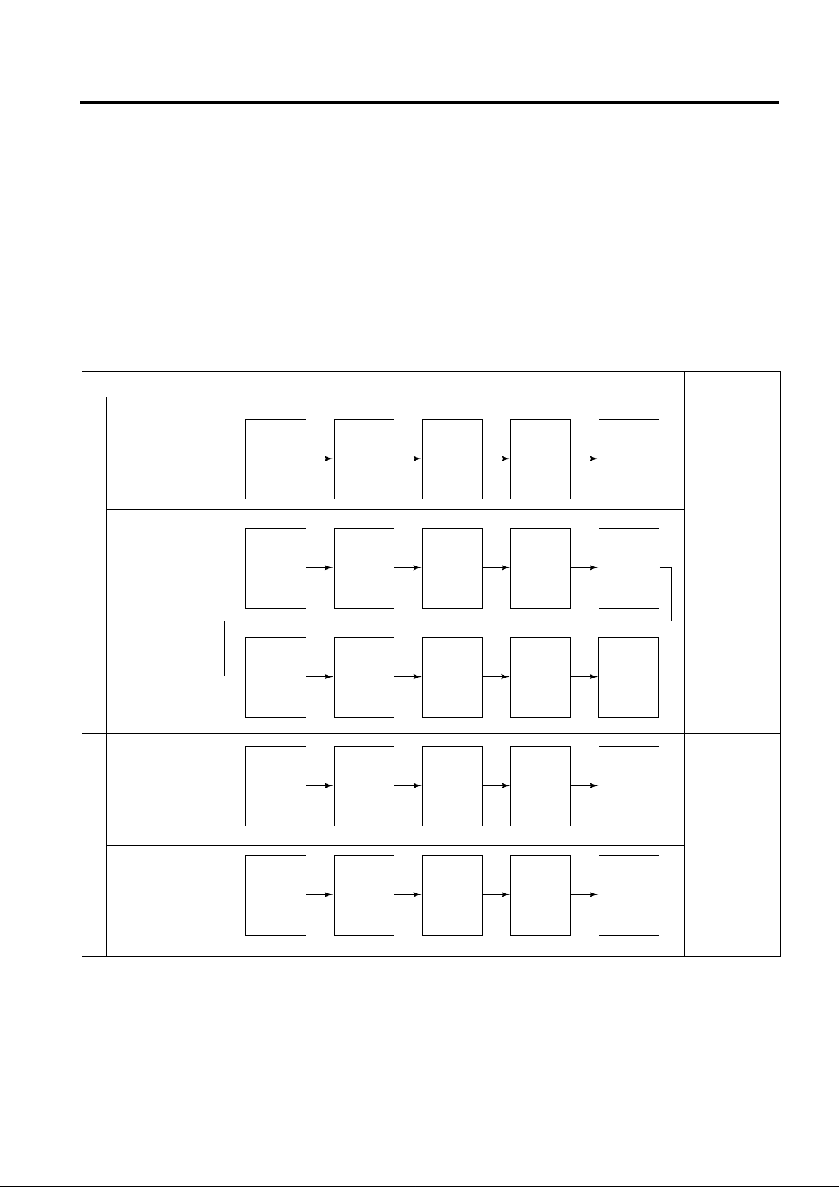
2-10. Sequential operation of built-in product
Built-in products such as compressor, frost removal heater, freezing room fan, Cooling Fan and step motor damper are
sequentially operated as follows for preventing noise and part damage occurred due to simultaneous operation of a lot of
parts in applying initial power and completing test.
MICOM FUNCTION
- 28 -
Function Load Operation Sequence Remark
In applying Initial power TEST MODE
When temperature
of a frost removal
sensor becomes
more than 25°C
(In purchase,
movement)
If error occurs
during operation,
initial operation is
not done.
If pressing switch
once more in the
test mode 2 or
temperature of a
frost removal
sensor is more
than 5°C, it
immediately
returns to the test
mode for initial
operation
(COMP operates
after 7 minutes).
When
temperature of a
frost removal
sensor becomes
less than 25°C
(In power failure,
service)
Test mode 1
(Compulsory
function)
Test mode 2
(Compulsory frost
removal)
POWER
ON
COMP
ON
COMP
ON
WATER
TANK
HEATER
ON
F-FAN
&
C-FAN
ON
F-FAN
&
C-FAN
ON
F-FAN
&
C-FAN
ON
F-FAN
&
C-FAN
OFF
WATER
TANK
HEATER
OFF
STEP
MOTOR
DAMPER
ON
STEP
MOTOR
DAMPER
OPEN
STEP
MOTOR
DAMPER
CLOSE
HOME
BAR
HEATER
ON
POWER
ON
FROST
REMOVAL
HEATER
ON
HOME
BAR
HEATER
OFF
HOME
BAR
HEATER
ON
TEST
S/W
(Press
Once)
COMP
ON
TEST
S/W
(Press
2 times)
COMP
OFF
0.5
sec.
0.3
sec.
0.3
sec.
0.3
sec.
0.5
sec.
8
sec.
0.3
sec.
5
sec.
FROST
REMOVAL
HEATER
OFF
FROST
REMOVAL
HEATER
ON
5
sec.
0.3
sec.
WATER
SUPPLY
&
DISPENSE
HEATER
ON
5
sec.
0.3
sec.
0.3
sec.
0.3
sec.
0.3
sec.
0.3
sec.
0.3
sec.
0.3
sec.
0.3
sec.
OTHER
LOAD
OFF
Page 10
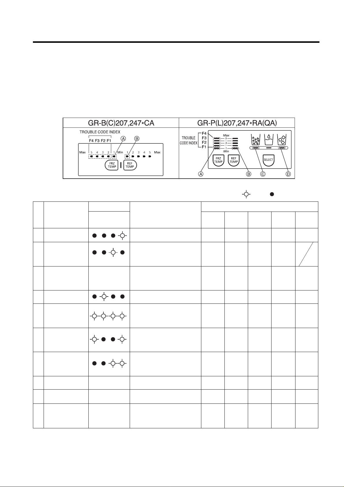
2-15. Failure Diagnosis Function
1. Failure diagnosis function is function to facilitate service when nonconforming matters affecting performance of product
during use of product.
2. In occurrence of failure, pressing the function adjustment button does not perform function and only alarm sound (“Ding~”) rings.
3. If nonconforming matters occurred are released during display of failure code, MICOM returns to the original state (Reset).
4. Failure code is displayed on the display part of setting temperature for the freezing room and the display part of setting
temperature for the cold storage room of LED, which are placed at the display part of a refrigerator. All the LED graphics
other than a failure code are turned off.
MICOM FUNCTION
- 29 -
: On : Off ●● : Normal
1
2
3
4
5
6
7
8
9
10
Note 1)
Note 1)
Note 1)
Note 1)
Trouble Code Indicator
F4 F3 F2 F1
No. Trouble items
Troubles
Freezer
Fan
Compressor
Stepping
Motor Damper
Defrost
Heater
Cooling
Fan
Operation Status During Trouble
Abnormal freezer(F)
sensor
Abnormal
refrigerator sensor
1(R1) (upper shelf
in the refrigerator)
Abnormal
refrigerator sensor
2(R2) (lower shelf in
the refrigerator)
Abnormal defrost
sensor
Faulty defrost
Abnormal freezer
BLDC fan motor
Abnormal cooling
BLDC fan motor
Abnormal room
temperature sensor
Abnormal icemaker
sensor
Abnormal icemaker
unit
Freezer sensor is cut or shortcircuited
Upper shelf refrigerator sensor is
cut or short-circuited.
Lower shelf refrigerator sensor is
cut or short-circuited.
Defrost sensor is cut or shortcircuited
Defrost heater and temperature
fuse are cut and disconnected.
(Indicates after at least four hours
when troubles occur)
No position-signal over 65s when
fan motor operate
No position-signal over 65s when
fan motor operate
Room temperature sensor (RTSensor) is cut or short-circuited.
Icemaker sensor is cut or shortcircuited.
Fauity motor or hall IC in
icemaker unit. Lead wire is cut or
shotr-circuited. Faulty motor
driving circuits
Standard
RPM
Standard
RPM
Standard
RPM
Standard
RPM
Standard
RPM
OFF (check
opeation per
30min. If normal
condition, reset)
●●
●●
●●
Standard
RPM
●●
●●
●●
●●
●●
●●
OFF (check
opeation per
30min. If normal
condition, reset)
●●
●●
●●
15 min on/
15 min off
●●
●●
●●
●●
●●
●●
●●
●●
●●
●●
●●
●●
No defrost
●●
●●
●●
●●
●●
●●
●●
●●
●●
●●
●●
●●
●●
●●
●●
Open for
10min
Close for
15min
Page 11
Note1) The abnormality of RT-Sensor, R2-Sensor Icemaker Unit, and Icemaker-Sensor is not indicated in trouble code but it
is indicated when checking LED (when pressing both freezer temperature control button and refrigerator temperature
control button for more than 1 second at the same time).
RT-Sensor Normal : A LED on, Abnormal : A LED Off.
R2-Sensor Normal : B LED on, Abnormal : B LED Off.
Icemaker Unit Normal : C LED on, Abnormal : C LED Off.
Icemaker Sensor Normal : D LED on, Abnormal : D LED Off.
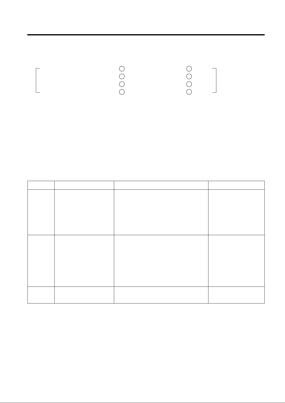
2-16. Test Function
1. The purpose of test function is to check function of the PCB and product and to search for the failure part at the failure
status.
2. Test button is placed on the main PCB of refrigerator (test switch), and the test mode will be finished after maximum 2
hours irrespective of test mode and then is reset to the normal status.
3. Function adjustment button is not perceived during performance of test mode but only warning sounds ring.
4. In finishing test mode, always pull the power cord out and then plug-in it again for the normal state.
5. If nonconforming contents such as sensor failure are found during performance of test mode, release the test mode and
display the failure code.
6. Even if pressing the test button during failure code display, test mode will not be performed.
MICOM FUNCTION
- 30 -
The rest of LEDs
are all on.
Test 1
Test 2
Normal
Conditions
MODE HANDLING CONTENTS REMARKS
Press TEST s/w once.
Press TEST s/w once at
TEST1 conditions.
Press TEST s/w once at
TEST2 conditions.
1. Compressor continuously operates.
2. Freezer fan (high speed RPM), Cooling fan
continuously operates.
3. Defrost heater is off.
4. All display LEDs are on.
5. Stepping motor damper is in open
conditions. (baffle is open)
1. Compressor is off
2. Freezer fan, Cooling fan are off.
3. Defrost heater is on.
4. All display LEDs are off. (Freezer room “2”
LED and Refrigerator room “2” LED are
only ON.)
5. Stepping motor damper is in closed. (baffle
is closed).
Returns to the initial conditions.
- Forced operate.
- Freezer fan is off when
door is opened.
- It returns to normal
conditions when the
temperature of defrost
sensor is above 5°C.
- Forced defrost.
Compressor starts after
seven minutes delay.
Page 12
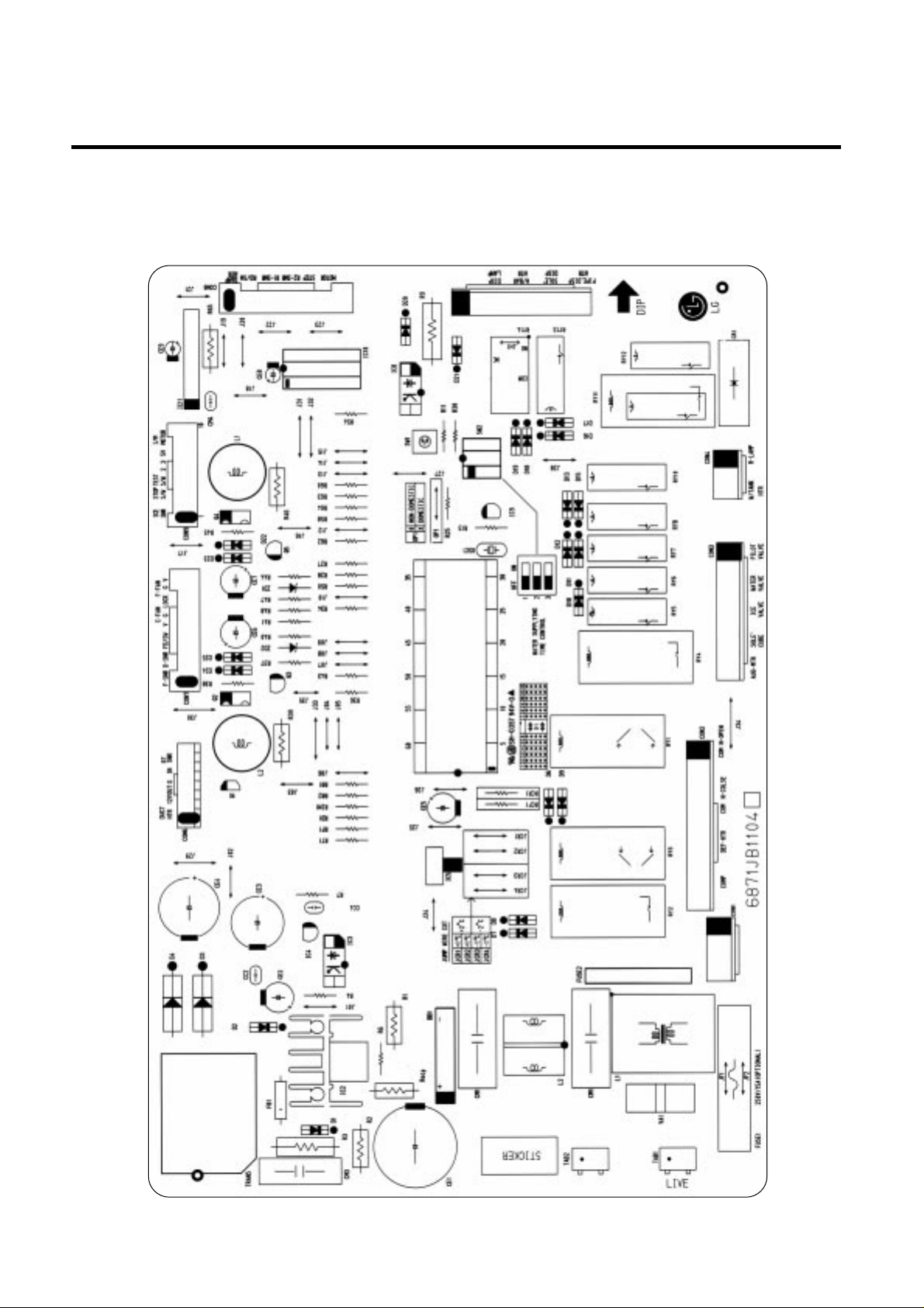
3. PWB parts diagram and list
3-1. PWB Ass’y, main part diagram
1. GR-P247, L247, P207, L207
EXPLATION FOR MICOM CIRCUIT
- 50 -
Page 13

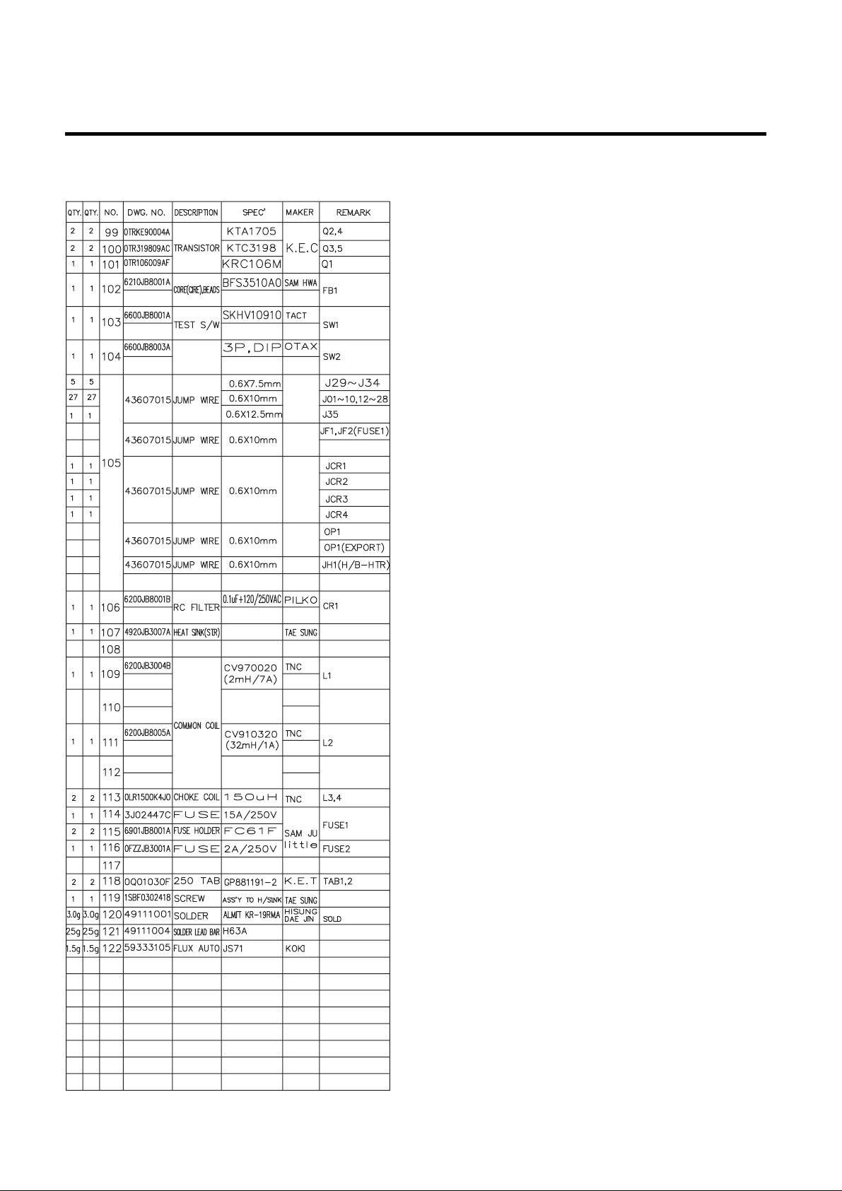
3-2. Parts list
1. GR-P247, L247, P207, L207
EXPLATION FOR MICOM CIRCUIT
- 52 -
Page 14
EXPLATION FOR MICOM CIRCUIT
- 53 -
WATER
SUPPLY
S/W
Page 15
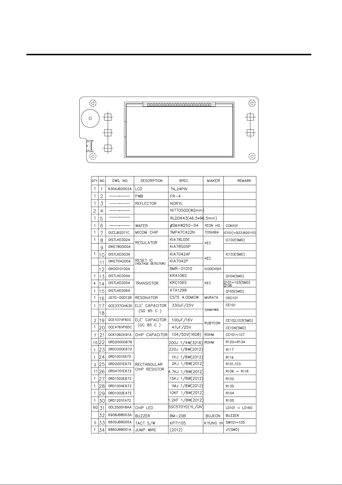
3-3. DISPLAY ASSY part diagram
1. GR-P247, L247, P207, L207
EXPLATION FOR MICOM CIRCUIT
- 56 -
DOUBLE SIDE TAPE
SPREAD SHEET
Page 16
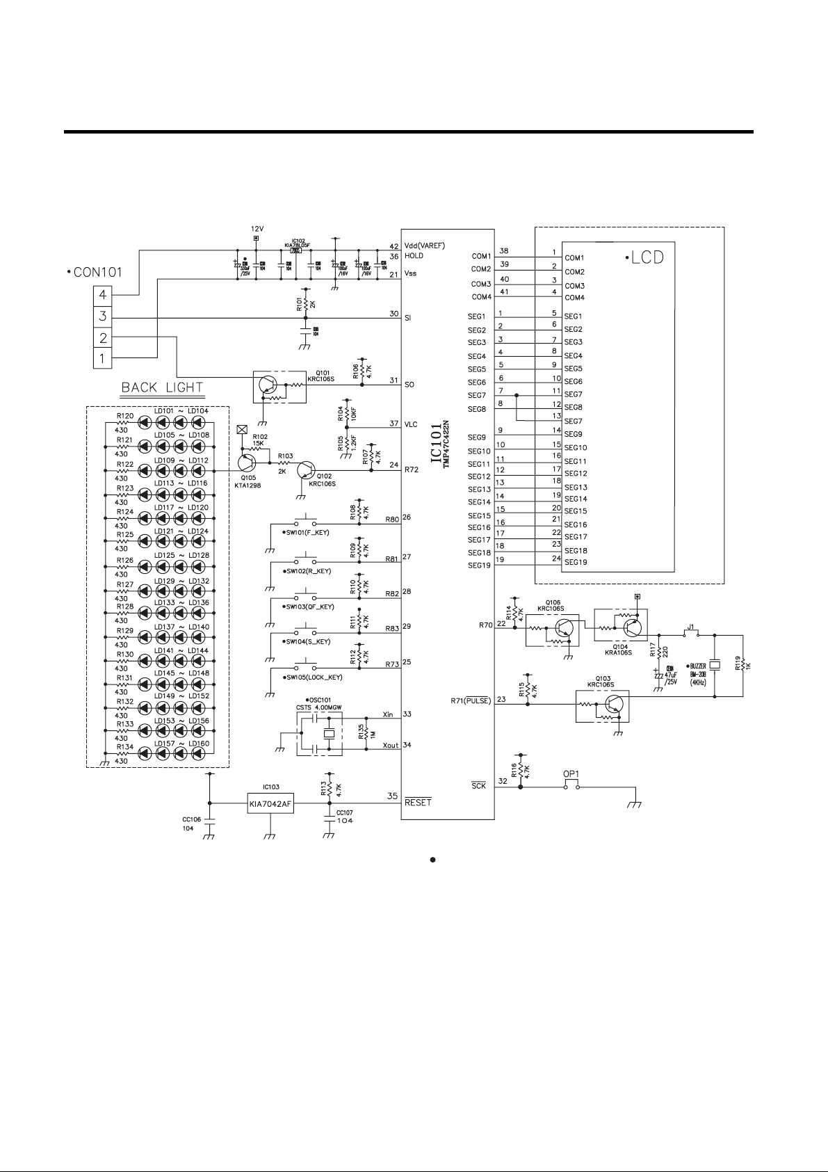
3-4. DISPLAY circuit diagram
1. GR-P247, L247, P207, L207
- 58 -
Parts without ( ) mark means SMD parts.
Reception
Transmission
Page 17
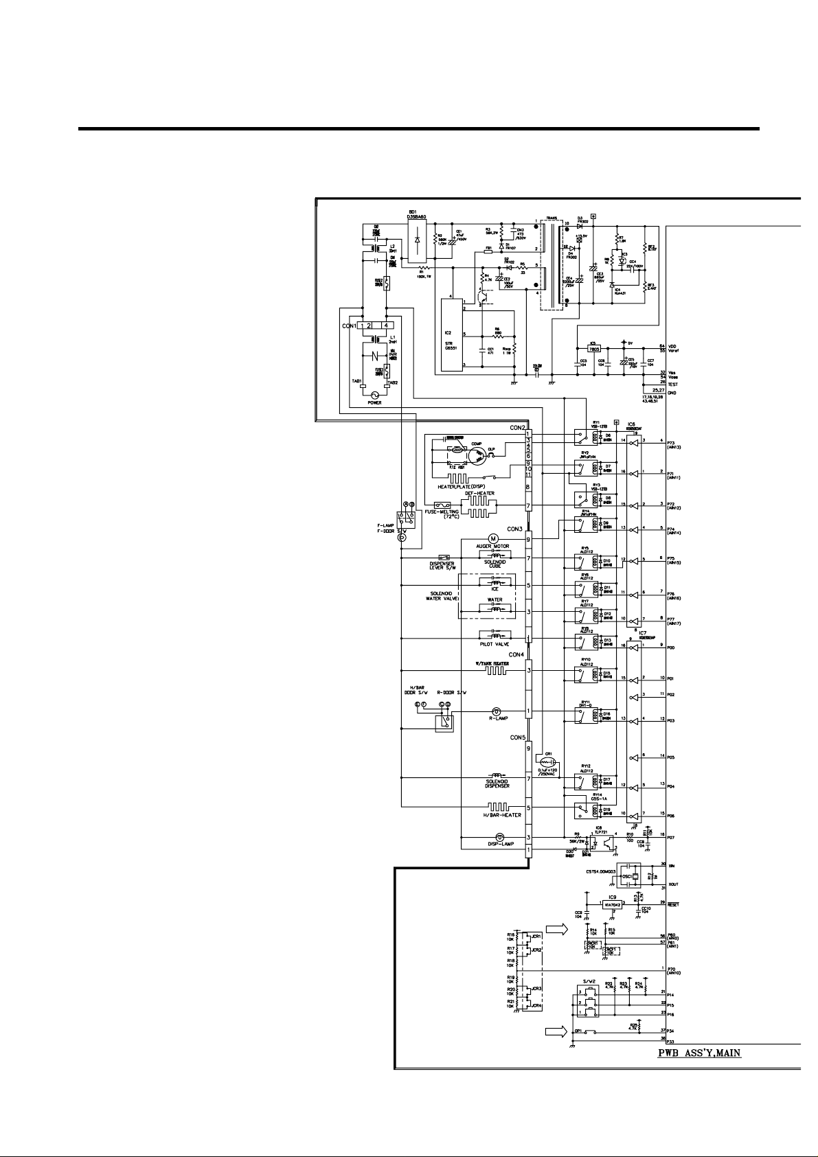
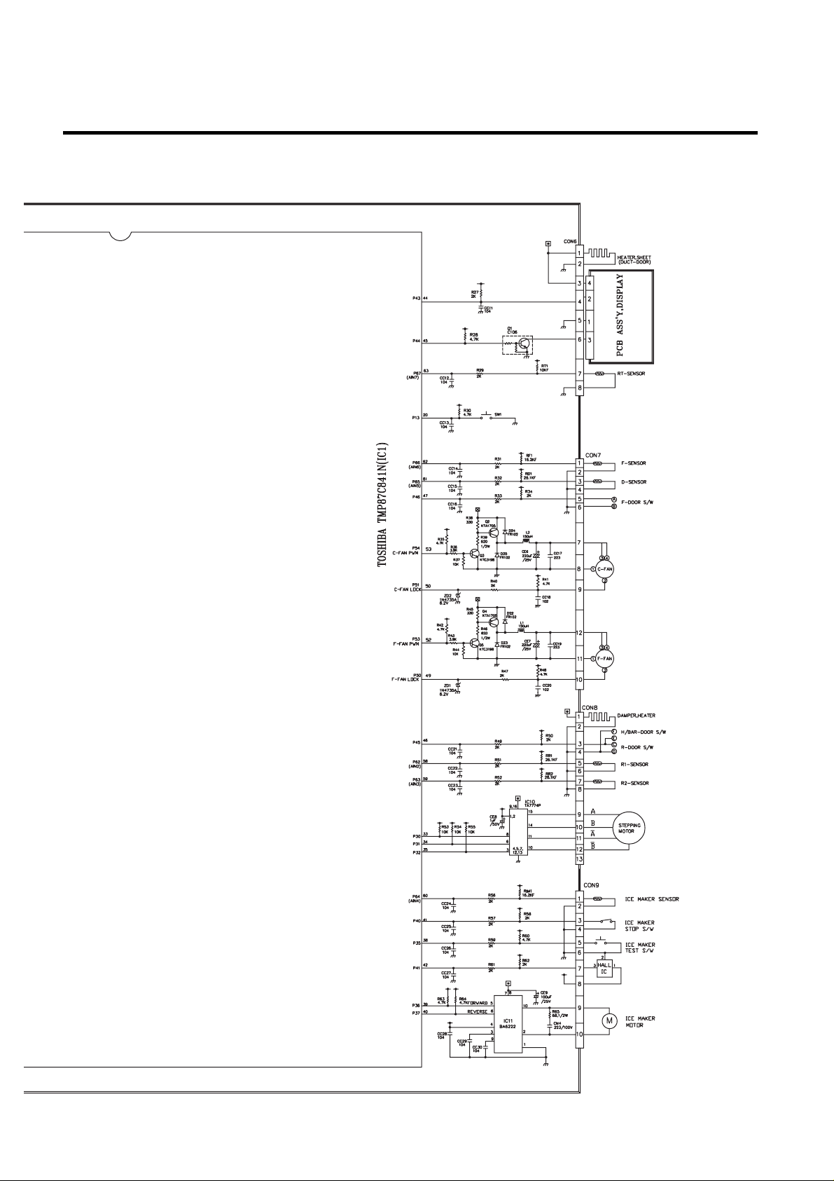
4. PWB circuit diagram - PWB circuit diagram may vary a little bit depending on actual condition.
1. GR-P247, L247, P207, L207
EXPLATION FOR MICOM CIRCUIT
- 60 -
Page 18
EXPLATION FOR MICOM CIRCUIT
- 61 -
Page 19
1. TROUBLE SHOOTING
TROUBLE DIAGNOSIS
- 72 -
CLAIMS. CAUSES AND CHECK POINTS. HOW TO CHECK
1. Faulty start
1) No power on outlet.
2) No power on cord.
3) Shorted start circuit.
4) During defrost.
* Measuring instrument :
Multi tester
■Check the voltage.
If the voltage is within ±85%
of the rated voltage, it is OK.
■ Check the terminal
movement.
■
Check both terminals of
power cord.
Power conducts : OK.
No power conducts : NG
■ Check both terminals of
O.L.P.
If power conducts : OK.
If not : NG.
■ Check the resistance of both
terminals.
At normal temperature 6 :
OK.
If disconnected : ∞.
Bad connection between adapter and outlet. (faulty adapter)
The Inner diameter of adapter.
The distance between holes.
The distance between terminals.
The thickness of terminal.
Bad connection between plug and adapter (faulty plug).
The distance between pins.
Pin outer diameter.
No power on
power cord.
O.L.P is off.
No electric power on compressor. - Faulty compressor .
Faulty PTC.
Disconnected copper wire.
Internal electrical short.
Faulty terminal contact.
Disconnected.
Capacity of O.L.P is small.
Characteristics of O.L.P is bad.
Bad connection.
Power is
disconnected.
Inner Ni-Cr wire blows out.
Bad internal connection.
Faulty terminal caulking (Cu wire is cut).
Bad soldering.
Weak connection.
Short inserted cord length.
Worn out tool blade.
Loose contact.
- Large distance between
male terminal.
- Thin female terminal.
T erminal disconnected.
Bad sleeve assembly .
Power cord is disconnected.
Faulty soldering.
Start automatic defrost.
Cycle was set at defrost when the refrigerator
was produced.
Power does not conduct. - Damage.
Bad characteristics. - Initial resistance is big.
Bad connection with
compressor.
Bad terminal connection.
T oo loose.
Assembly is not possible.
Page 20

TROUBLE DIAGNOSIS
- 73 -
CLAIMS. CAUSES AND CHECK POINTS. HOW TO CHECK
2. No cooling.
2) Refrigeration system is clogged.
■Check the clogged
evaporator by heating (as
soon as the cracking sound
begins, the evaporator start
freezing)
■ The evaporator does not cool
from the beginnig (no evidece
of misture attached).
The evaporator is the same
as before even heat is
applied.
Moisture
clogged.
No electric
power on
thermostat.
Weld joint
clogged.
Drier cloggeing.
Foreign material clogging.
Residual moisture
in the evaporator.
Residual moisture.
Insufficient drier
capacity.
Residual moisture
in pipes.
Moisture penetration - Leave it in the air. - Moisture penetration.
into the refrigeration oil.
Caps are missed.
Air blowing.
During transportation.
During work.
Not performed.
Performed.
T oo short time.
Low air pressure.
Less dry air.
Air Blowing.
Leave it in the air.
Caps are missed.
Short pipe insert.
Pipe gaps.
T oo much solder .
T oo large.
Damaged pipes.
Not dried in the compressor.
Elapsed more than 6 months after drying
Caps are missed.
No pressure when it is open.
During rest time.
After work.
Compressor cap is disconnected.
Foreign materials are in the pipe.
Not performed.
T oo short.
Impossible moisture
confirmation.
Low air pressure.
Dry drier - Drier temperature.
Leave it in the air.
The capillary tube inserted depth. - T oo much.
Capillary tube melts. - Over heat.
Clogged with foreign materials.
Reduced cross section by cutting. - Squeezed.
Desiccant powder.
Weld oxides.
Drier angle.
Check on package
condition.
Good storage after
finishing.
Page 21

TROUBLE DIAGNOSIS
- 74 -
CLAIMS. CAUSES AND CHECK POINTS. HOW TO CHECK
3. Refrigeration
is weak.
Plate
heater
Cord
heater
1) Refrigerant Partly leaked.
2) Poor defrosting capacity.
Drain path (pipe) clogged.
Defrost heater does not
generate heat.
Weld joint leak.
Parts leak.
Inject P/U into drain hose.
Foreign materials
penetration.
Cap drain is not disconnected.
Inject through the
hole.
Seal with drain.
P/U lump input.
Screw input.
Other foreign materials
input.
Parts
disconnected.
Wire is cut.
- Heating wire.
- Contact point
between heating
and electric wire.
Dent by fin evaporator.
Poor terminal contacts.
Wire is cut.
- Lead wire.
- Heating wire.
- Contact point
between heating and
electric wire.
Heating wire is corroded
- Water penetration.
Bad terminal connection.
■Check visually.
■Check terminal
Conduction: OK.
No conduction: NG.
If wire is not cut, refer to
resistance.
P=Power
V=Voltage
R=Resistance
V
2
P= —
R
V
2
R= —
P
Page 22

- 75 -
TROUBLE DIAGNOSIS
CLAIMS. CAUSES AND CHECK POINTS. HOW TO CHECK
3. Refrigeration
is weak.
3) Cooling air leak.
4) No cooling air circulation.
Residual
frost.
No automatic defrosting.
Defrost does not return.
Bad gasket adhestion
Door sag.
Faulty fan motor.
Weak heat from heater.
Bad heater assembly .
T oo short defrosting time. Defrost Sensor.
- Faulty characteristics.
Seat-D(missing, location. thickness).
Structural fault. Gasket gap.
Air inflow through the fan motor.
Bad insulation of case door.
Sheath Heater - rated.
Heater plate - rated.
Heater cord-L - rated.
Heater plate
Heater cord-L
Gap.
Bad attachment.
Contraction.
Bad adhesion.
Weak binding force at hinge.
Fan motor.
Door switch.
Self locked.
Wire is cut.
Bad terminal contact.
Contact distance.
Button pressure.
Melted contact.
Contact.
Poor door
attachment.
Door liner
(dimension).
Contraction inner
liner.
Misalignment.
Bad terminal
connection.
P/U liquid leak.
Faults.
Refrigerator and freezer switch reversed.
Button is not pressed.
No contact to drain.
Loosened stopper cord.
Not contact to the
evaporator pipe.
Location of assembly
(top and middle).
■Check the fan motor
conduction: OK.
No conduction: NG.
Page 23

TROUBLE DIAGNOSIS
- 76 -
CLAIMS. CAUSES AND CHECK POINTS. HOW TO CHECK
3. Refrigeration
is weak.
4) No cooling air circulation.
5) Compressor capacity.
6) Refrigerant
too much or too little.
7) Continuous operation
- No contact of temperature controller. - Foreign materials.
8) Damper opens continuously.
Foreign materials
jammed.
Failed sensor. - Position of sensor.
Characteristics
of damper.
9) Food storing place. - Near the outlet of cooling air.
Faulty fan motor.
Small cooling air
discharge.
Fan is
constrained.
Insufficient
motor RPM
Faulty fan.
Shorud. Bent.
Ice and foreign materials on rotating parts.
Fan shroud contact. - Clearance.
Damping evaporator contact.
Accumulated residual frost.
Fan misuse.
Bad shape.
Loose connection. - Not tightly connected.
Insert depth.
Rating misuse.
Small capacity.
Low valtage.
Malfunction of charging cylinder.
Wrong setting of refrigerant.
Insufficient compressor. - Faulty compressor .
Fan overload. - Fan misuse.
Bad low termperature RPM characteristics.
Rated power misuse.
Low voltage.
P/U liquid dump.
EPS water sediment.
Screw.
Bad characteristics of its own temperatue.
Parts misuse.
Charge of temperature - Impact.
characteristics.
■Check visually after
disassembly.
■Check visually after
disassembly.
Page 24

TROUBLE DIAGNOSIS
- 77 -
CLAIMS. CAUSES AND CHECK POINTS. HOW TO CHECK
4. Warm
refrigerator
compartment
temperature.
5. No automatic
operation.
(faulty
contacts.)
6. Dew and
ice formation.
1) Colgged cooling path.
2) Food storate.
1) Faulty temperature sensor in freezer or refrigerator compartment.
2) Refrigeration load is too much.
3) Poor insulation.
4) Bad radiation.
5) Refrigerant leak.
6) Inadequate of refrigerant.
7) Weak compressor discharging power.
8) Fan does not work.
9) Button is positioned at "strong."
1) Ice in freeezer compartment.
2) Condensation in the refrigerator compartment.
3) Condensation on liner foam.
P/U liquid leak.
Foreign materials. –– P/U dump liquid.
Faulty contact.
Faulty temperature characteristics.
External air inflow. –– Rubber motor assembly direction(reverse).
Door opens
but not closes.
Gap around gasket. –– Contraction, distortion, loose, door twisted, corner not
fully inserted.
Food vapor. –– Storing hot food. –– Unsealed food.
Door opens
but not closes.
Gasket gap.
Cool air leak
and transmitted.
High ambient temperature.
Space is secluded.
Different rating.
Small capacity.
Store hot food.
Store too much at once.
Door open.
Packages block air flow.
Food.
Frequent opening and closing.
Cool air leak.
Poor door close. – Partly opens.
T oo much food.
Hot food.
Weak door closing power.
Stopper malfunction.
Door sag.
Food hinders door closing.
Insufficient closing.
Door sag.
Food hinders door closing.
T oop table part.
Out plate R/L part.
Not fully filled.
Flange gap. –– Not sealed.
Gasket gap.
■Inspect parts measurements
and check visually.
Page 25

TROUBLE DIAGNOSIS
- 78 -
CLAIMS. CAUSES AND CHECK POINTS. HOW TO CHECK
6. Dew and
ice formation.
7. Sounds
4) Dew on door.
Dew on the duct door. - Duct door heater is cut.
Dew on the dispense
recess.
Dew on the door surface. Not fully filled. Surface.
Cormer.
P/U liquid contraction.
Dew on the
gasket surface.
5) Water on the floor.
Dew in the refrigerator compartment.
Defrosted water overflows. Clogged discharging hose.
Discharging hose Evaporation tray located at wrong place.
location.
Tray drip. Damaged.
Breaks, holes.
Small Capacity.
Position of drain.
1) Compressor compartment operating sounds.
Compressor sound Sound from machine itself.
inserted. Sound from vibration.
Restrainer.
Rubber Too hard.
seat. Distorted.
Aged.
Burnt.
Stopper. Bad Stopper Not fit
assembly. (inner
diameter
of stopper).
Tilted.
Not
Compressor base not connected.
Bad welding compressor stand(fallen).
Foreign materials in the compressor
compartment.
O.L.P.
sound.
Chattering
sound.
Insulation paper vibration.
Capacitor noise.
Pipe contacts each other. – Narrow interval.
Pipe sound. No vibration damper. Damping rubber-Q.
Damping rubber-S.
Capillary tube unattached.
Recess Heater is cut.
Duct door is open. / Foreign material clogging.
Bad wing adhesion. Wing sag(lower part).
Door liner shape mismatch.
Corner. T oo much notch.
Broken.
Home Bar heater is cut.
Liquid shortage.
Liquid leak.
Page 26

TROUBLE DIAGNOSIS
- 79 -
CLAIMS. CAUSES AND CHECK POINTS. HOW TO CHECK
7. Sounds
1) Compressor compartment operating sounds.
Transformer
sound.
Drip tray vibration sound.
Back cover machine sound.
Condenser drain sound.
2) Freezer compartment sounds.
Fan motor sound.
Sounds from fan
contact.
Unbalance fan sounds.
Motor shaft
contact sounds.
Resonance.
Evaporator noise.
3) Bowls and bottles make contact on top shelf.
4) Refrigerator roof contact.
5) Refrigerator side contact.
6) Insufficient Lubricants on door hinge.
Its own fault. –– Core gap.
Bad connection. –– Correct screw connection.
Bad assembly.
Distortion.
Foreign materials inside.
Bad connection.
Partly damaged.
Not connected.
Bad pipe caulking.
Normal operating sound.
Vibration sound.
Aged rubber seat.
Bad torque for assembling motor
bracket.
Fan guide contact.
Shroud burr contact.
Damping evaporator contact.
Residual frost contact.
Unbalance.
Ice on the fan. –– Air intake (opposite to motor
rubber assembly.)
Supporter disorted.
Tilted during motor assembly .
Evaporator pipe contact. –– No damping evaporator.
Sound from refrigerant. –– Stainless steel pipe shape in
accumulator.
Sound from fin evaporator and pipe during expansion
and contraction.
Poor treatment Cord heater.
Narrow evaporator interval.
Surface machining conditions.
Fan distortion.
Misshappen.
Burr.
Page 27

TROUBLE DIAGNOSIS
- 80 -
CLAIMS. CAUSES AND CHECK POINTS. HOW TO CHECK
8. Faulty lamp
(freezer and
refrigerator
compartment).
9. Faulty internal
voltage(short).
1) Lamp problem. Filament blows out.
Glass is broken.
2) Bad lamp assembly. Not inserted.
Loosened by vibration.
3) Bad lamp socket.
Disconnection. Bad soldering.
Bad rivet contact.
Short. Water penetration. Low water
level in tray.
Bad elasticity of contact.
Bad contact(corrosion).
4) Door switch. Its own defect.
Refrigerator and freezer switch is reversed.
Travlel distance.
Bad connection.
Bad terminal contact.
P/U liquid leak..
1) Lead wire is damaged.
Wire damage when assembling P.T.C. Cover.
Outlet burr in the bottom plate.
Pressed by cord heater. lead wire, evaporator pipe.
2) Exposed terminal.
Compressor Compartment terminal. - Touching other
components.
Freezer compartment terminal. - Touching evaporator pipe.
3) Faulty parts.
Transformer. Coil contacts cover.
Welded terminal parts contact cover.
Compressor. Bad coil insulation.
Plate heater.
Melting fuse. Sealing is broken. Moisture penetration.
Cord heater. Pipe damaged. Moisture penetration.
Bad sealing.
Sheath heater.
■Connect conduction and
non-conduction parts and
check with tester.
Conduction: NG.
Resistance∞: OK.
Page 28

TROUBLE DIAGNOSIS
- 81 -
CLAIMS. CAUSES AND CHECK POINTS. HOW TO CHECK
10. Structure,
appearance
and others.
1) Door foam.
Sag.
Noise during
operation.
Malfunction.
2) Odor.
Temperature of
refrigerator
compartment.
Deodorizer.
Food Storage.
Others.
Weak torque of
hinge connection.
Weak gasket
adhesion.
Fixed tape.
Hinge interference.
Not closed Interference between door liner and inner liner.
Refrigerator
compartment is
opened when freezer
compartment is
closed (faulty stopper).
High. Faulty damper control.
Button is set at "weak".
Door is open (interference by
food).
No deodorizer.
Poor capacity.
Seal condition.
Store special odorous food.
Long term storage.
Odors from chemical procucts.
Bigger door foam.
Hinge-Pin tilted-Poor flatness.
No washer.
No grease and not enough
quantity.
Stopper worn out.
Bad freezer compartment door
assembly.
No stopper.
Bolt is loosened during
transportaion.
Not tightly fastened.
Screw worn out .
Adhesion surface.
Not well fixed.
Page 29

2. Faults
2-1. Power
2-2. Compressor
TROUBLE DIAGNOSIS
-82-
Problems Causes Checks Measures Remarks
No power on - Power cord cut. - Check the voltage with tester. -Replace the components.
outlet. - Faulty connector insertion. - Check visually. -Reconnect the connecting parts.
- Faulty connection between plug - Check visually. - Reconnect the connecting parts.
and adapter.
Fuse blows out. - Short circuit by wrong connection. - Check the fuse with tester - Find and remove the cause of - Replace with rated
- Low voltage products are or visually. problem(ex. short, high voltage, fuse after confirming
connected to high voltage. - Check the input volt are with tester low voltage). its specification.
- Short circuit by insects. (between power cord and products). - Replace with rated fuse.
- Electricity leakage. - Check the resistance of power cord
■ If fuse blowns out
- High voltage. with testerf (if it is 0Ω, it is shorted). frequently, reconfirm
- Short circuit of components the cause and prevent.
(tracking due to moisture and dust
penetration).
Problems Causes Checks Measures Remarks
Compressor - Faulty PTC. - Check the resistance. - If resistance is infinite, replace it
does not Vlaue:∞ is defective. with new one.
operate. - If it is not infinite, it is normal.
- Check other parts.
- Compressor is frozen. - If compressor assembly parts are - During forced operation:
normal(capacitor, PTC, OLP), - Operates: Check other parts.
apply power directly to the - Not operate: Replace the frozen
compressor to force operation. compressor with new one, weld,
evacuate, and recharge refrigerant.
OLP It starts as soon as it is • Refer to weld repair procedures.
contacted.
Auxiliary winding
Main winding
Power
Page 30

2-3. Temperature
TROUBLE DIAGNOSIS
-83-
Problems Causes Checks Measures Remarks
High Poor cool air circulation due to faulty - Lock –– Check resistance with a - Replace fan motor.
temperature fan motor. tester.
in the freezer 0Ω: short.
compartment. ∞Ω: cut. - Reconnect and reinsert.
- Rotate rotor manually and check
rotation.
- Wire is cut.
- Bad terminal contact: Check - Maintain clearance and remove ice
terminal visually. (Repair and/or replace shroud if fan
- Fan constraint. – Fan shroud is constrained by shroud
contact: Confirm deformation).
visually.
– Fan icing:
Confirm visually.
Faulty fan motor due to faulty door - Iced button (faulty) operation: - Confirm icing causes and repair.
switch operation. Press button to check - Replace door switch.
- Faulty button pressure and contact:
Press button to check operation.
- Door cannot press door switch - Door sag: fix door.
button: Check visually. - Door liner bent:replace door or
attach sheets.
Bad radiation conditions in - Check the clearance between the - Keep clearance between - The fan may be
compressor compartment. refrigerator and wall (50 mm in refrigerator and walls (minimum broken if cleaning
minimum). 50mm). performs while the
- Check dust on the grill in - Remove dust and contaminants refrigerator is on.
compressor compartment. from grill for easy heat radiation.
- Check dust on the coils condenser. - Remove the dust with vacuum
cleaner from the coils condenser
while the refrigerator is off.
Page 31

2-4. Cooling
TROUBLE DIAGNOSIS
-84-
Problems Causes Checks Measures Remarks
High Refrigerant leak. Check sequence
Weld the leaking part, recharge the Drier must be replaced.
temperature 1. Check the welded parts of the refrigerant.
in the freezer drier inlet and outlet and drier
compartment. auxiliary in the compressor
compartment (high pressure side).
2. Check the end of compressor
sealing pipe (low pressure side).
3. Check silver soldered parts.
(Cu + Fe / Fe + Fe).
4. Check bending area of wire
condenser pipe in compressor
compartment (cracks can
happen during bending).
5. Check other parts (compressor
compartment and evaporators in
freezer compartment).
Shortage of refrigerant. Check frost formation on the surface - Find out the leaking area, repair, Drier must be replaced.
of evaporator in the freezer evacuate, and recharge the
compartment. refrigerant.
- If the frost forms evenly on the - No leaking, remove the remaining
surface, it is OK. refrigerant, and recharge new
- If it does not, it is not good. refrigerant.
Page 32

TROUBLE DIAGNOSIS
-85-
Problems Causes Checks Measures Remarks
High Cycle pipe is clogged. Check sequence. - Heat up compressor discharging Direr must be replaced.
temperature in 1. Check temperature of condenser weld joints with touch, disconnect
the freezer manually. the pipes, and check the clogging.
compartment. If it is warm, it is OK. Remove the causes of clogging,
If it is not, compressor discharging weld, evacuate, and recharge
joints might be clogged. the refrigerant.
2. Manually check whether hot line - If it's warm, it's OK. If it's not,
pipe is warm. condenser discharging line weld
If it is warm, it's OK. joints might be clogged.
If it is not, condenser outlet weld Disconnect with torch, remove the
joints might be colgged. causes, evacuate, and recharge
seal refrigerant.
Leak at loop pipe weld joint Check sequence. Replace the compressor, weld, Drier must be replaced.
(discharge) in compressor. 1. Manually check whether evacuate, and recharge refrigerant.
condenser is warm, It is not warm
and the frost forms partly on the
evaporator in the freezer
compartment.
Faulty cooling fan in the compressor Check sequence. - Replace if motor does not operate.
compartment. 1. Check cooling fan operation. - If fan is disconnected, check fan
2. Check that cooling fan is damage and reassemble it.
disconnected from the motor. ■ Refer to fan motor disassembly
and assembly sequence.
Page 33

2-5. Defrosting failure
TROUBLE DIAGNOSIS
-86-
Problems Causes Checks Measures Remarks
No defrosting. Heater does not generate heat as 1. Check the resistance of heater. Heating wire is short and wire is cut. Seal the lead wire with
the heating wire is cut or the circuit 0Ω: Short. ∞Ω: Cut. • Parts replacement: Refer to parts insulation tape and heat
is shorted. Tens to thousands Ω: OK. explanations. contraction tube if the cut
1) Heating wire is damaged when 2. Check the resistance between lead wire is accessible to
inserting into the evaporator. housing terminal and heater repair.
2) Lead wire of heater is cut. surface.
3) Heating wire at lead wire contacts 0Ω: Short. ∞Ω: Cut.
is cut. Tens to thousands Ω: Short.
Sucking duct and discharging hole 1. Confirm foreign materials. In case 1) Push out impurities by inserting
are clogged: of ice, insert the copper line copper wire.(Turn off more than
1. Impurities. through the hole to check. 3hours and pour in hot water if
2. Ice. 2. Put hot water into the drain frost is severe.)
(check drains outside). 2) Put in hot water to melt down frost.
3) Check the water outlet.
4) Push the heater plate to sucking
duct manually and assemble the
disconnected parts.
Gap between Sucking duct and 1. Confirm in the Sucking duct. 1) Turn off the power, confirm
Heater plate(Ice in the gap). impurities and ice in the gap, and
supply hot water until the ice in the
gap melts down.
2) Push the Heater plate to drain
bottom with hand and assemble
the disconnected parts.
Wrong heater rating (or wrong 1. Check heater label. Faults:replace.
assembly). 2. Confirm the capacity after - How to replace: Refer to main parts.
substituting the resistance value
into the formula.
(V: Rated voltage of user country)
(R: Resistance of tester[Ω])
Compare P and lavel capacity.
Tolerance: ±7%
V
2
P= ––
R
Page 34

TROUBLE DIAGNOSIS
-87-
Problems Causes Checks Measures Remarks
No defrosting Melting fuse blows out. - Check melting fuse with tester. - Faullty parts: parts replacement.
1) Lead wire is cut. If 0Ω: OK. - Check wire color when maeasuring
2) Bad soldering. If ∞Ω: wire is cut. resistance with a tester.
Ice in the Sucking duct. 1. Check the inner duct with mirror. 1) Turn power off.
1) Icing by foreign materials in the 2) Raise the front side(door side),
duct. support the front side legs, and let
2) Icing by cool air inflow through the ice melt naturally. (If power is
the gap of heater plate. on, melt the frost by forced
3) Icing by the gap of heater plate. defrosting.)
2. Check by inserting soft copper 3) Reassemble the heater plate.
wire into the duct (soft and thin
copper not to impair heating wire).
Bad cool air inflow and discharge, 1. Turn on power, open or close the 1) Check the faulty connector of
and bad defrosting due to faulty door, check that motor fan housing and reassemble wrongly
contact and insertion (bad connector operates (If it operates, motor fan assembled parts.
insertion into housing of heater, is OK). 2) If the parts are very damaged,
melting, fuse and motor fan). 2. Disconnect parts in the refrigerator remove the parts and replace it
compartment, check the connection
with a new one.
around the housing visually,
defrost, and confirm heat generation
on the heater. Do not put hands on
the sheath heater.
3. Check the parts which have faults
described in 1, 2 (mechanical
model: disconnect thermostat
from the assembly).
Page 35

2-6. Icing
TROUBLE DIAGNOSIS
-88-
Problems Causes Checks Measures Remarks
Icing in the 1) Bad circulation of cool air. - Check the food is stored properly - Be acquainted with how to use. - Check the defrost
refrigerator - Clogged intake port in the (check discharge and intake port - Sealing on connecting parts. related parts if problem
compartment. refrigerator compartment. are clogged). - Check the damper and replace is caused by faulty
- Damper icing. - Sealing is not good. - Check icing on the surface of it if it has defects. defrosting.
- Pipe icing. - Too much food is stored and clogs baffle and cool air path (pipe) after - Check defrost. (After forced
- Discharging the discharge port. dissembling the container box. defrosting, check ice in the
pipe icing. - Bad defrosting. - Check icing at intake ports of evaporator and pipes.)
freezer and refrigerator
compartment.
2) Faulty door or refrigerator - Check gasket attached conditions. - Correct the gasket attachment - Replacement should
compartment. - Check door assembly conditions. conditions and replace it. be done when it
- Faulty gasket. - Door assembly and replacement. cannot be repaired.
- Faulty assembly.
3) Overcooling in the refrigerator - Check refrigerator compartment - Replace faulty parts.
compartment. is overcooled (when button
- Faulty damper in the refrigerator pressed on "weak").
compartment. - Check parts are faulty.
- Faulty MICOM (faulty sensor)
4) Bad defrosting - Check frost on the evaporator - Check parts related to defrosting. - Moisture cannot frost
- Heater wire is cut. after dissembling shroud and fan - Check defrosting. (Check ice on the on the evaporator but
- Defective defrost sensor. grille. evaporator and pipe.) can be sucked into the
- Defrosing cycle. - Check ice on intake port of freezer refrigerator, being
and refrigerator compartment. condensed and iced,
interferes with cool air
circulation, and
suppresses sublimation.
5) Customers are not familiar with - Check food interferes with door - Be acquainted with how to use.
this machine. closing.
- Door opens. - Check ice on the ceilings.
- High temperature, high moisture,
and high load.
Page 36

TROUBLE DIAGNOSIS
-89-
Problems Causes Checks Measures Remarks
Ice in the freezer 1) Bad cooling air circulation. - Check food storage conditions - Be acquainted with how to use. - Check the parts related
compartment. - Intake port is colgged in the freezer visually.(Check clogging at intake - Check defrost (Check ice on the to defrosting if the
- Surface of fan compartment. and discharging port of cooling air.) evaporator and pipes after forced problem is caused by
grille. - Discharging port is Clogged. - Check food occupation ratio in defrosting). the faulty defrosting.
- Wall of freezer - Too much food is stored. volume(Less than 75%).
compartment. - Bad defrosting. - Check frost on the evaporator after
- Cool air dissembling shroud and fan grille.
discharging port.
- Check icing at intake port of
- Basket(rack) refrigerator compartment.
area.
- Food surface. 2) Bad freezer compartment door - Check gasket attachment - Correct the gasket attachement - Replace when it can not
- Icing in the - Faulty gasket conditions. conditions and replace it. be repaired.
shute. - Faulty assembly - Check door assembly conditions. - Door assembly and replacement.
3) Over freezing in the freezer - Refrigerator operates pull down. -Replace defective parts.
compartment. (Check if it is operated
- Faulty MICOM. intermittently)
- The Temperature of freezer
compartment is satisfactory, but
over freezing happens in the
refrigerator compartment even
though the notch is set at "weak".
4) Bad defrosting. - Check frost on the evaporator after - Check parts related to defrosting.
- Heater wire is cut. dissembling shroud and grille. - Check defrosting.(Check ice on the
- Faulty defrost sensor. - Check ice on the intake port in the evaporator and pipes after forced
- Defrosting cycle refrigerator compartment. defrosting.)
5) User is not familiar with how to - Check food holds door open. - Be acquainted with how to use.
use. - Check ice on the ice tray.
- Door opens.
- High moisture food(water) is stored.
Page 37

2-7. Sound
TROUBLE DIAGNOSIS
-90-
Problems Causes Checks Measures Remarks
"Whizz" sound 1. Loud sound of compressor 1.1 Check the level of the 1) Maintain horizontal level.
operation. refrigerator. 2) Replace rubber and seat if they
1.2 Check the rubber seat are sagged and aged.
conditions (sagging and aging). 3) Insert rubber where hand contact
reduces noise in the pipe.
2. Pipes resonat sound which is 2.1 Check the level of pipes 4) Avoid pipe interference.
connected to the compressor. connected to the compressor 5) Replace defective fan and fan
and their interference. motor.
2.2 Check rubber inserting 6) Adjust fan to be in the center of
conditions in pipes. bell mouth of the fan guide.
2.3 Touch pipes with hands or screw 7) Leve a clearance between
-driver (check the change of interfering parts and seal gaps in
sound). the structures.
8) Reassemble the parts which make
3. Fan operation sound in the freezer 3.1 Check fan insertion depth and sound.
compartment. blade damage. 9) Leave a clearance if evaporator
3.2 Check the interference with pipes and suction pipe touch
structures. freezer shroud.
3.3 Check fan motor.
3.4 Check fan motor rubber insertion
and aging conditions.
4. Fan operation sound in the 4.1 Same as fan confirmation in the
compressor compartment. refrigerator.
4.2 Check drip tray leg insertion.
4.3 Check the screw fastening
conditions at condenser and
drip tray.
Page 38

TROUBLE DIAGNOSIS
-91-
Problems Causes Checks Measures Remarks
Vibration sound. 1. Vibration of shelves and foods in 1-1. Remove and replace the 1) Reassemble the vibrating parts
("Cluck") the refrigerator. shelves in the refrigerator and insert foam or cushion where
2. Pipes interference and capillary 1-2. Check light food and container vibration is severe.
tube touching in the compressor. on the shelves. 2) Leave a clearance where parts
compartment. 2-1. Touch pipes in the compressore interfere with each other.
3. Compressor stopper vibration. compartment with hands. 3) Reduce vibration with rubber
4. Moving wheel vibration. 2-2 Check capillary tube touches and restrainer if it is severe.
5. Other structure and parts cover back. (especially, compressor and pipe).
vibration. 3-1 Check compressor stopper 4) Replace compressor stopper if it
vibration. vibtates severely.
4-1 Check vibration of front and rear
moving wheels.
5-1 Touch other structures and parts.
Irregular sound. 1. It is caused by heat expansion 1-1 Check time and place of sound 1)
Explain the principles of refrigeration
("Click"). and contraction of evaporator, sources.
and that the temperature difference
shelves, and pipes in the
between operation and defrosting
refrigerator.
can make sounds.
2)
If evaporator pipe contacts with other
structures, leave a clearance between
them (freezer shroud or inner case).
Page 39

TROUBLE DIAGNOSIS
-92-
Problems Causes Checks Measures Remarks
Sound "Burping" It happens when refrigerant expands
- Check the sound of refrigerant at the - Check the restrainer attached on the
(almost the same at the end of capillary tube. initial installation. evaporator and capillary tube weld
as animals crying - Check the sound when the refrigerator joints and attach another restrainer.
sound). starts operation after forced defrosting. - If it is continuous and servere, insert
- Check the restrainer attachment capillary tube again (depth:15±3mm)
conditions on the evaporator and - Fasten the capillary tube to suction
capillary tube weld joints. pipes or detach in the compressor
compartment.
- Explain the principles of freezing
cycles.
Water boiling or It happens when refrigerant passes - Check the sound when compressor is - Explain the principles of freezing cycles
flowing sound. orifice in accumulator internal pipes by turned on. and refrigerant flowing phenomenon by
the pressure difference between - Check the sound when compressor is internal pressure difference.
condenser and evaporator. turned off. - If sound is servere, wrap the
accumulator with foam and restrainer.
Sound of whistle When door closes, the internal pressure - Check the sound by opening and - Broaden the cap of discharge hose for
when door of the refrigerator decreases sharply closing the refrigerator or freezer doors. defrosting in the compressor
closes. below atomosphere and sucks air into compartment.
the refrigerator, making the whistle - Seal the gap with sealant between out
sound. and inner cases of hinge in door.
Page 40

2-8. Odor
TROUBLE DIAGNOSIS
-93-
Problems Causes Checks Measures Remarks
Food Odor. Food (garlic, kimchi, etc) - Check the food is not wrapped. - Dry deodorizer in the shiny and
- Check the shelves or inner windy place.
wall are stained with food juice. - Store the food in the closed
- Check the food in the vinyl wraps. container instead of vinyl wraps.
- Chedk food cleanliness. - Clean the refrigerator and set
button at "strong".
Plastic Odor. Odors of mixed food and plastic - Check wet food is wrapped with - Clean the refrigerator.
odors. plastic bowl and bag. - Persuade customers not to use
- It happens in the new refrigerator. plastic bag or wraps with wet food
or odorous foods.
Odor from the Odor from the old deodorizer. - Check the deodorizer odors. - Dry the deodorizer with dryer and *Deodorizer : option
deodorizer. then in the shiny and windy place.
- Remove and replace the
deodorants.
Page 41

2-9. Micom
TROUBLE DIAGNOSIS
-94-
Problems Symptom Causes Checks Measures Remarks
Bad PCB All display Bad connection Bad connector Visual check on connector Reconnect
electric power. LCD are off. between Main PCB connection from main connection. connector.
and display circuit. PCB to display PCB.
Defective PCB trans. PCB Trans winding is Check resistance of PCB Trans Replace PCB Trans Applicable to
cut. input and output terminals with or PCB. model without
PCB Trans temperature a tester. (If resistance is infinity, dispenser.
fuse is burnt out. trans winding is cut).
DefectivePCB electric Defective regulator IC Check voltage at input/output Replace regulator. Refer to electric
circuit parts. (7812, 7805). terminals. circuit in circuit
explanation.
PCB electric terminal Check fuse in PCB electric Replace PCB fuse.
fuse is burnt out. terminal with a tester.
STR Parts are Check if STR No. 2 and 3 pins Replace parts. Applicable to
damaged. are cut when power is off. model with
dispenser.
Abnormal Bad connection Lead Wire connecting Check Lead Wire terminals Reconnect Lead
display LCD between Main PCB main PCB and display connecting Main PCB and Wire and directly
operation and display circuit. PCB is cut or connector display PCB with a tester. connect defective
terminal connection is contact terminal to
bad. Lead Wire.
Defective LCD. Defective LCD. Check if all LCD are on when Replace display Refer to display
Main PCB Test switch is PCB. circuit in circuit
pressed (or when both freezer explanation.
key and power freezer key are
pressed at the same time for
more than one second.)
Page 42

TROUBLE DIAGNOSIS
-95-
Problems Symptom Causes Checks Measures Remarks
Bad cooling. Freezer Compressor does Compressor Lead Wire Check compressor Lead Wire Reconnect Lead
temperature is not start. is cut. with a tester. Wire.
high. Defective compressor Measure voltage at PCB CON2 Replace relay(RY1 Refer to load
driving relay. (3&9) after pressing main PCB and RY2) or PCB. driving circuit in
test switch once. It is OK if circuit
voltage is normal. explanation.
Defective freezer Defective Freezer Check resistance of freezer Replace freezer Refer to
sensor. sensor parts. sensor with a tester. sensor. resistance
characteristics
table of sensor in
circuit
Freezer sensor is Confirm the color of sensor in Repair main PCB explanation.
substituted for other circuits (main PCB sensor sensor housing
sensor. housing).
Defective freezer fan Fan motor lead wire Check fan motor lead wire Reconnect lead
motor. is cut. with a tester. wire.
• Defective door switch Measure the voltage between • Replace door Refer to load
(freezer, refrigerator, PCB power blue line and fan switch
(freezer,
driving circuits in
home bar). motor after pressing test switch
refrigerator
and circuit
• Defective fan motor. of Main PCB. If the voltage is home bar). explanation.
• Defective fan motor normal, it is OK. • Replace fan motor.
driving relay.
Faulty defrost. Refer to faulty defrost items in trouble diagnosis Refer to trouble
functions. diagnosis
function.
Page 43

TROUBLE DIAGNOSIS
-96-
Problems Symptom Causes Checks Measures Remarks
Bad cooling Wrong Defective Step Motor Check Step Motor Check if Step Motor damper Reconnect lead
Refrigerator Damper. damper motor and motor and reed switch lead wire.
temperature. reed switch and lead wire are cut with a tester.
wire are cut. Check Refer to Step Motor damper Replace Step Motor
Step Motor damper in parts repair guide. damperor refrigerator
part. control box Assy.
Check Step Motor Refer to Step Motor damper Replace relay or Refer to single
damper Motor driving in parts repair guide. PCB. motor damper
relay in PCB. driving circuits
in circuit
explanation.
Foreign materials in Step
Check Step Motor damper Remove foreign
Motor damper baffles. baffle visually. materials.
Ice formation on Check if Step Motor damper Replace Step Motor
Step Motor damper Heater wire is cut with a
damper or refrigerator
baffles. tester. control Box Assy.
Defective refrigerator Defective refrigerator Check the resistance of Replace refrigerator Refer to sensor
sensor sensor parts. refrigerator sensor with a tester. sensor. resistance
characteristic
table in circuit
explanation.
Refrigerator sensor is Check the sensor color in the Repair main PCB
substituted for other circuit. (main PCB sensor sensor housing.
sensor. housing.)
Defective refrigerator Check if refrigerator sensor Fix again the
sensor assembly is not fixed at cover sensor but refrigerator sensor.
condition. inner case visually.
Page 44

TROUBLE DIAGNOSIS
-97-
Problems Symptom Causes Checks Measures Remarks
Bad defrost. Defrost is not Defrost lead wire is cut. Check if defrost lead wire is cut with a Reconnect Lead
working. tester. Wire.
Defective defrost driving relay. Check the voltage of CON2 (1 and 7) Replace relay (RY 7 Refer to load
with a tester after pressing main and RY 3) or PCB. driving conditions
PCB test switch twice. check in circuit
If the voltage is normal then it is OK. explanation.
Defective defrost sensor parts. Check the resistance of defrost sensor Replace defrost Refer to sensor
with a tester. sensor. resistance
characteristic
table of circuit
explanation.
Defective Buzzer Defective connecting lead wire from Check lead wire related to door Repair lead wire.
buzzer continuously main PCB to door switch. switch with a tester.
rings or door Defective door switch parts. Refer to door switch in parts repair Replace door switch.
opening alarm guide.
does not work.
Defective Buzzer does Key input wire is cut or bad connector Check input wire with a tester. Reconnect lead Refer to display
display button not ring and terminal contact in main PCB and wire and replace or circuit in circuit
key does not display PCB connecting lead wire. directly connect bad explanation.
sense even contact terminal to
button is lead wire.
pressed.
Key is continuously depressed due to Disassemble frame display and confirm Adjust or replace
structural interference. visually. interfering
structures.
Page 45

TROUBLE DIAGNOSIS
-98-
Problems Symptom Causes Checks Measures Remarks
Defective Buzzer rings Trouble mode indication. Check trouble diagnosis function. Repair troubles Refer to mode
display button. but key does indication in
not sense even function
button is explanations.
pressed.
Door Buzzer Buzzer Defective connecting lead wire from Check lead wire associated with door Repair lead wire. Check model
continuously main PCB to door switch. switch. with dispenser.
rings or door Defective freezer compartment door Refer to door switch in parts repair Replace Freezer
opening alarm switch parts. guide. compartment door
does not work. switch.
Bad water/ice Ice and water Defective connecting lead wire from Check Lead Wire associated with lever Repair lead wire.
dispenser. are not Main PCB to lever switch. switch with a tester.
dispensed. Defective lever switch parts Refer to door switch in parts repair guide. Replace lever switch.
Defective photo coupler IC parts. Check voltage change at photo coupler Replace photo
output terminals with lever switch coupler IC or PCB.
pressed. It is OK if voltage change is
between 0V - 5V.
Defective relay associated with ice Check relay (RY4, RY5, RY12) Replace defective
dispense (geared motor, cube and with a tester. relay.
dispenser solenoid).
Defective parts associated with ice Check resistance of parts with a tester. Replace defective
dispense (geared motor, cube and parts.
dispenser solenoid).
Defective relay associated with water Check relay (RY7) with a tester Replace defective
dispense. relay.
Defective parts associated with water Check resistance of parts with a tester. Replace defective
dispenser. parts.
Page 46

3. Cooling Cycle Heavy Repair
3-1. The Heavy Repair Standards for Refrigerator with R134a Refrigerant
NOTE) Please contact Songso company on +82-53-554-2067 if you have inquiry on heavy repair special facility.
TROUBLE DIAGNOSIS
- 99 -
NO. Items Unit Standards Purposes Remarks
1 Pipe and piping Min. Pipe:within 1 hour. To protect The opening time should be reduced to a
system opening time. Comp:within Moisture half of the standards during rain and
10 minutes. Penetration. rainy seasons (the penetration of water
Drier:within into the pipe is dangerous).
20 minutes.
2 Welding. Nitrogen Weld under To protect - Refet to repair note in each part.
Pressure. Nitrogen oxide scale - R134a refrigerant is more susceptible to
atmosphere formation. leaks than R12 and requires more care
(N
2 pressure: during welding.
0.1~0.2 kg/cm
2
) - Do not apply force to pipes before and
after welding to protect pipe from
cracking.
3N
2 sealed parts. Confirm N2 Confirm air leaking To protect - In case of evaporator parts, if it doesn't
leak. sounds when moisture noise when removing rubber cap blow
removing rubber penetration. dry air or N
2 gas for more than 1 min
cap. use the parts.
Sound:usable
No sound:
not usable
4
Refrigeration
Evacuation
Min. More than To remove
Cycle. time 40 minutes. moisture.
Vacuum Torr Below 0.03(ref) Note:Only applicable to the model
degree equipped with reverse flow protect
plate.
Vacuum EA High and low Vaccum efficiency can be improved by
Pressure sides are operating compressor during evacuation.
evacuated at the
same time for
models above 200
L
Vacuum EA Use R134a To protect The rubber pipes for R12 refrigerant shall
piping exclusive mixing of be melted when they are used for R134a
manifold. mineral and refrigerant(causes of leak).
ester oils.
Pipe EA Use R134a To protect
coupler cxclusive. R12 Refri-
gerant mixing.
Outlet R134a exclusive.
˝
(Socket)
Plug R134a exclusive
˝
5 Refrigerant weighing. EA Use R134a Do not mix - Do not weight the refrigerant at too hot or
exclusively. with R12 too cold an area.(25°C is adequate.)
Weighing refrigerant. - Use copper bombe
allowance:±5g Socket:2SV Plug: 2PV R134a
Note:Winter:-5g Note:Do not burn O-ring (rubber) during
Summer:+5g welding.
6 Drier replacement. -
Use R134a exclusively
To remove
for R134a refrigerator
the moisture
-
Use R12 exclusively
from pipe.
for R12 refrigerator
-
Replace drier whenever
repairing refrigerator
cycle piping.
7 Leak check. -Do not use soapy Detect -Check oil leak at refrigerant leak area.
water for check. refrigerant Use electronic leak detector if oil leak is
it may be sucked leak area. not found.
into the pipe by. -The electronic leak detector is very
sensitive to halogen gas in the air. It also
can detect R141b in urethane. Please
practice, therfore, many times before use.
Page 47

3-2. Summary Of Heavy Repair
TROUBLE DIAGNOSIS
- 100 -
Process Contents Tools
- Cut charging pipe ends and discharge refrigerant from Filter, side cutters
drier and compressor.
- Use R134a oil and refrigerant for compressor and drier Pipe Cutter, Gas welder, N
2 gas
- Confirm N
2 sealing and packing conditions before use.
Use good one for welding and assembly.
- Weld under nitrogen gas atmosphere.(N
2 gas pressure:
0.1-0.2kg/cm
2
).
- Repair in a clean and dry place.
- Evacuate for more than forty minutes after connecting Vacuum pump(R134a
manifold gauge hose and vacuum pump to high (drier) exclusively), Manifold gauge.
and low (compressor refrigerant discharging parts)
pressure sides.
- Evacuation Speed:113
l/min.
- Weigh and control the allowance of R134a bombe in a R134a exclusive bombe(mass
vacuum conditions to be ±5 g with electronic scales and cylinder), refrigerant(R134a)
charge through compressor inlet manifold gauge, electronic
(Charge while refrigerator operates). scales, punching off flier,
- Weld carefully after inlet pinching. gas welding machine
- Check leak at weld joints. Electronic Leak Detector,
Minute leak: Use electronic leak detector Driver(Ruler).
Big leak: Check visually or fingers.
Note:Do not use soapy water for check.
- Check cooling capacity
➀ Check radiator manually to see if warm.
➁ Check hot line pipe manually to see if warm.
➂ Check frost formation on the whole surface of the
evaporator.
- Remove flux from the silver weld joints with soft brush Copper brush, Rag, Tool box
or wet rag.(Flux may be the cause of corrosion and
leaks.)
- Clean R134a exclusive tools and store them in a clean
tool box or in their place.
- Installation should be conducted in accordance with the
standard installation procedure.(Leave space of more
than 5 cm from the wall for compressor compartment
cooling fan mounted model.)
Trouble
diagnosis
Remove refrigerant
Residuals
Parts
replacement
and welding
Compressor
compartment
and tools
arrangement
Transportation
and
installation
Check
refrigerant leak
and cooling
capacity
Vacuum
Refrigerant
charging and
charging
inlet welding
Page 48

3-3. Precautions During Heavy Repair
TROUBLE DIAGNOSIS
- 101 -
Items Precautions
1. Use of tools. 1) Use special parts and tools for R134a.
2. Removal of retained 1) Remove retained refrigerant more than 5 minutes after turning off a refrigerator.
refrigerant. (If not, oil will leak inside.)
2) Remove retained refrigerant by cutting first high pressure side (drier part) with a nipper and
then cut low pressure side. (If the order is not observed, oil leak will happen.)
3. Replacement of drier. 1) Be sure to replace drier with R134a only when repairing pipes and injecting refrigerant.
4. Nitrogen blowing 1) Weld under nitrogen atmosphere in order to prevent oxidation inside a pipe.
welding. (Nitrogen pressure : 0.1~0.2 kg/cm
2
.)
5. Others. 1) Nitrogen or refrigerant R134a only should be used when cleaning inside of cycle pipes
inside and sealing.
2) Check leakage with an electronic leakage tester.
3) Be sure to use a pipe cutter when cutting pipes.
4) Be careful not the water let intrude into the inside of the cycle.
Compressor
Evaporator
Drier
2
Low pressure side
Condenser
1
High pressure side
Page 49

3-4. Practical Work For Heavy Repair
TROUBLE DIAGNOSIS
- 102 -
Items Precautions
1. Removal of residual
refrigerant.
1) Remove residual refrigerant more than 5 minutes later after turning off the refrigerator.
( If not, compressor oil may leak inside.)
2) Remove retained refrigerant slowly by cutting first high pressure side (drier part) with a
nipper and then cut low pressure side.
2. Nitrogen blowing
welding.
When replacing a drier:
Weld
a and b parts by blowing nitrogen(0.1~0.2kg/cm2) to high pressure side after
assembling a drier.
When replacing a compressor:
Weld a and b parts by blowing nitrogen to the low pressure side.
Note) For other parts, nitrogen blowing is not necessary because it does not produce oxidized
scales inside pipe because of its short welding time.
3. Replacement of drier.
Inserting a capillary tube
Measure distance with a ruler and put a mark(12
+3/-0
)on the capillary tube. Insert tube to the
mark, and weld it
KEYPOINTING
Observe the sequence for
removal of refrigerant.
(If not, compressor oil may
leak.)
KEYPOINTING
Welding without nitrogen
blowing produces oxidized
scales inside a pipe, which
affect on performance and
reliability of a product.
KEYPOINTING
Be sure to check the
inserted length of capillary
tube when it is inserted. (If
too much inserted, a
capillary tube is clogged by
a filter.)
Compressor
Low pressure side
Condenser
High pressure side
Drier
Evaporator
Release
Refrigent
Intake
Suction
1 2 1
2
Evaporator
Drier
High pressure side
Condenser
Refrigent
Intake
12
+3
-0
Filter
* Unit : mm
Page 50

TROUBLE DIAGNOSIS
- 103 -
Items Precautions
4.Vacuum degassing.
Pipe Connection
Connect a red hose to the high pressure side and a blue hose to the
low pressure side.
Vacuum Sequence
Open a, b valves and evacuate for 40 minutes. Close valve a.
5.Refrigerant charging.
Charging sequence
1) Check the amount of refrigerant supplied to each model after completing vacuum
degassing.
2) Evacuate bombe with a vacuum pump.
3) Measure the amount of refrigerant charged.
- Measure the weight of an evacuated bombe with an electronic scale.
- Charge refrigerant into a bombe and measure the weight. Calculate the weight of
refrigerant charged into the bombe by subtracting the weight of an evacuated bombe.
KEYPOINTING
- If power is applied
during vacuum
degassing, vacuum
degassing shall be
more effective.
- Operate compressor
while charging
refrigerant. (It is
easier and more
certain to do like
this.)
KEYPOINTING
- Be sure to charge
the refrigerant at
around 25°C.
- Be sure to keep -5g
in the winer and
+5g in summer
the amount of refrigerant charged= a weight after charging a weight before charging (a weight of an evacuated cylinder)
Calculation of amount of refrigerant charged
Blue
Evaporator
Drier
2 1
Low
pressure
Yellow
Compressor
3
Suction pipe
Condenser
Vaccum
Pump
High
pressure
Red
Indicate the weight of
an evacuated bombe
R134a
Page 51

3-5. Standard Regulations For Heavy Repair
TROUBLE DIAGNOSIS
- 104 -
Items Precautions
4) Refrigerant Charging
Charge refrigerant while operating a compressor as shown above.
5) Pinch a charging pipe with a pinch-off plier after completion of charging.
6) Braze the end of a pinched charging pipe with copper brazer and take a gas leakage test
on the welded parts.
6. Gas-leakage test * Take a leakage test on the welded or suspicious area with an electronic leakage tester.
7. Pipe arrangement Check each pipe is placed in its original
in each cycle place before closing a cover back-M/C
after completion of work. Particularly
control the size of Joint Drain Pipe
1) Observe the safety precautions for gas handling.
2) Use JIG (or wet towel) in order to prevent electric wires from burning during welding. (In order to prevent insulation
break and accident.)
3) The inner case shall be melted and insulation material (polyurethane) shall be burnt if not cared during welding inner
case parts.
4) The copper pipe shall be oxidized by overheating if not cared during welding.
5) Not allow the aluminum pipes to contact to copper pipes. (In order to prevent corrosion.)
6) Observe that the inserted length of a capillary tube into a drier should be 12 mm.
7) Make sure that the inner diameter should not be distorted while cutting a capillary tube.
8) Be sure that a suction pipe and a filling tube should not be substituted each other during welding. ( High efficiency
pump.)
+3
-0
Evaporator
Compressor
Drier
Condenser
Bombe
Rubber
Molecular
Sieves
12 mm
Drier
Molecular Pipe
+3
-0
Page 52

3-6. Brazing Reference Drawings
TROUBLE DIAGNOSIS
- 105 -
PIPE ASSY, JOINT
PIPE ASSY, HOT LINE
(Freezer)
PIPE ASSY, HOT LINE
(Refrigerator)
PIPE ASSY, JOINT
CONDENSER ASSY, WIRE
PIPE ASSY, SUCTION
DRIER ASSYCAPI - TUBE
Copper Brazer
Copper
Brazer
Silver Brazer
Copper
Brazer
Copper Brazer
Copper Brazer
Coppper Brazer
Silver Brazer
Copper
Brazer
Page 53

4. HOW TO DEAL WITH CLAIMS
4-1. Sound
TROUBLE DIAGNOSIS
- 106 -
Problems Checks and Measures
"Whizz" sounds ■ Explain general principles of sounds.
• All refrigerator when functioning properly have normal operating sound. The
compressor and fan produce sounds.
There is a fan in the freezer compartment which blows cool air to freezer and
refrigerator compartments. "Whizz" sounds are heard when the air passes
through the narrow holes into the freezer and refrigerator compartments.
■ Cooling Fan sound in the compressor compartment.
• There is a fan on the back of the refrigerator, which cools the compressor
compartment. If there is a small space between the refrigerator and the wall, the
air circulation sounds may be noticeable.
■ Noise of Compressor.
• This operating sound happens when the compressor compresses the
refrigerant. The compressor rotates at 3600RPM. The sound of compressor
operation becomes louder as the refrigerator capacity increases.
"Click" sounds ■Explain the principles of temperature change.
• The sounds happens when pipes and internal evaporator in the refrigerator
compartment expand and contract as the temperature changes during the
refrigerator operation. This sound also happens during defrosting, twice a day,
when the ice on the evaporator melts.
"Clunk" sound ■ Explain that it comes from the compressor when the refrigerator starts.
• When the refrigerator operates, the piston and motor in the compressor rotate
at 3600RPM. This sound is caused by the vibration of motor and piston when
they start and finish their operation. This phenomena can be compared with that
of cars. When the car engine ignites and starts to rotate, the loud sound
becomes gradually quiet. When the engine stops, it stops with vibration.
Vibration sound ■ Check the sound whether it comes from the pipes vibration and friction.
• Insert rubber or leave a space between pipes to avoid the noise.
• Fix the fan blade if the noise is due to the collision of fan and shroud.
• Fix the drip tray if it is loosened.
■ Sound depends on the installation location.
• Sound becomes louder if the refrigerator is installed on a wooden floor or near a
wooden wall. Move it to the another location.
• If the refrigerator is not leveled properly, a small vibration can make a loud
sound. Please adjust the level of the refrigerator.
Page 54

TROUBLE DIAGNOSIS
- 107 -
Problems Checks and Measures
Sounds of water flowing ■ Explain the flow of refrigerant.
• When the refrigerator stops, the water flowing sound happens.
This sound happens when the liquid or vapor refrigerant flows from the
evaporator to compressor.
"Click" sounds ■Explain the characteriistics of moving parts.
• This noise comes from the MICOM controller's switch on the top of the
refrigerator when it is turned on and off.
Noise of ice maker operation ■ Explain the procedure and principles of ice maker operation.
(applicable to model with ice maker). • Automatic ice maker repeats the cycle of water supplying ➝ icemaking ➝ ice
- Noise produced by ice dropping ejection. When water is supplied, the water supply valve in the machine room
and hitting ice bank. makes sounds like “Whizz” and water flowing also makes sound. When water
- Noise from motor sounds “Whizz”. freezes to ice, freezing sounds such as “click, click” are heard. When ice is
being ejected, sounds like “Whizz” produced by a motor to rotate an ice tray
and ice dropping and hitting ice bank sounds are also heard.
Noise when supplying water. ■ Explain the principles of water supplied to dispenser.
• When the water supply button in the dispenser is pressed, the water supply
valve in the compressor compartment opens and let the water flow to the water
tank in the lower part of the refrigerator compartment. The water is dispensed
by this pressure. When this happens, motor sound and water flowing sound are
heard.
Noise when supplying ice. ■ Explain the principles of ice supply and procedure of crushed ice making in a
dispenser.
• When ice cube button is pressed, ice stored in the ice bank is moved by a Helix
Pusher and dispensed. If crushed ice button is pressed, the cube ice is
crushed. When this happens, ice crushing and hitting ice bank sounds are
heard.
Page 55

4-2. Measures for Symptoms on Temperature
TROUBLE DIAGNOSIS
- 108 -
Problems Checks and Measures
Refrigeration is weak. ■ Check temperature set in the temperature control knob.
• Refrigerator is generally delivered with the button set at “normal use” (MID).
But customer can adjust the temperature set depending on their habit and taste.
If you feel the refrigeration is weak, then set the temperature control button at
“strong” position. If you adjust the button in the freezer compartment as well,
the refrigeration is stronger than adjusting refrigerator only.
The food in the chilled drawer is . ■ The chilled drawer does not freeze food.
not frozen but defrosted • Use chilled drawer for storing fresh meat or fish for short periods. For storing for
a long periods or freezing food, use a freezer compartment. It is normal that
frozen foods thaw above the freezing temperature (in the chilled drawer).
Refrigerator water is not cool. ■ Check the water storage location.
• If water is kept in the door rack, please ask to keep it in the refrigerator
compartment shelf. It will then become cooler.
Ice cream softens. ■ Explain the characteristics of ice cream.
• The freezing point of ice cream is below -15°C. Therefore ice cream may melt if
it is stored in the door rack.
• Store ice cream in a cold place or set the temperature control button of a freezer
at “strong” position.
Refrigeration is too strong. ■ Check the position of temperature control button.
• Check if refrigeration is strong in whole area of the refrigerator or partly near the
outlet of the cooling air. If it is strong in whole area, set the control button at
“weak”. If it is strong only near the outlet of cool air, keep food (particularly wet
and easy to frozen such as bean curd and vegetables) away from the outlet.
Vegetables are frozen. ■ Check the vegetables storage.
• If vegetables are stored in the refrigerator shelf or chilled drawer instead of
vegetable drawer, they will be frozen. Set the control button at “weak” if they are
also frozen in the vegetable drawer.
The food stored at inside of ■ Check if food is stored near the outlet of the cooling air.
the shelf freezes even the • The temperature at cooling air outlet is always below the freezing point.
control button is set at “MID”. Do not store food near the outlet of the cooling air as it block the air circulation.
And do not block the outlet. If the outlet of the cooling air is blocked, the
refrigerator compartment will not be cooled.
Page 56

4-3. Odor and Frost
TROUBLE DIAGNOSIS
- 109 -
Problems Checks and Measures
Odor in the refrigerator compartment.
■ Explain the basic principles of food odor.
• Each food has its own peculiar odor. Therefore it is impossible to prevent or
avoid food odor completely when food is stored in the completely sealed
refrigerator compartment. Deodorizer can absorb some portions of the odor but
not completely. The intensity of odor depends on refrigerator conditions and
environments.
■ Check the temperature control button and set at “strong”.
• Clean inside of the refrigerator with detergent and remove moisture. Dry inside
the refrigerator by opening the door for about 3 or 4 hours and then set the
temperature control button at “strong”.
Frost in the freezer compartment ■ Explain the basic principles of frost formation.
• The main causes for frosting:
- Door was left open.
- Air penetration through the gasket
- Too frequent door opening. (parties. etc.)
- Hot foods are stored before they are cooled down. The temperature of freezer
is -19°C. if temperature is set at “MID”. If hot air comes into the refrigerator,
fine frost forms as cold air mixes with hot air. If this happens quite often, much
frost forms inside of the refrigerator. If the door is left open in Summer, ice may
form inside of the refrigerator.
Frost in ice tray. ■ Explain basic principles of frost formation.
• When ice tray with full of water is put into a freezer compartment, the water
evaporates. If cool air fan operates, the moisture attached to the jaw (protruded
part) of ice mold shall freeze and form frost. If warm water was put into the ice
mold, the situation will become worse.
Page 57

4-5. Others
TROUBLE DIAGNOSIS
- 110 -
Problems Checks and Measures
The refrigerator case is hot. ■ Explain the principles of radiator.
• The radiator pipes are installed in the refrigerator case and partition plate
between the refrigerator and the freezer compartment in order to prevent
condensation formation. Particularly in summer or after installation of
refrigerator, it may feel hot but it is normal. If there is no enough space to
dissipate heat, it can be hotter due to lack of heat radiation. Please install a
refrigerator in a well-ventilated place and leave a clearance between refrigerator
and wall:
Small holes in a door liner ■ Explain that the hole is for releasing gas.
• A small hole in the door liner is for releasing gas during insulation materials
lining work. With a releasing hole, forming can be easily done .
Electric bills are too much. ■ Check the use conditions.
• Too frequent door opening and hot food storing cause the compressor to
operate continuously and hence increase the electric consumption and bills.
Condensation on the inside ■ Explain how to store foods
wall of the refrigerator • Condensation forms when refrigerator is installed at damp area, door is
compartment and the cover of frequently opened, and wet foods are not stored in the air tight container or
properly vegetable drawer. wrapped. Be sure to store wet foods in the air tight container or in the wrap.
When is the power connected? ■ When should the power be connected ?
• You can connect the power right after the installation. But if the refrigerator was
laid flat during transportation for a long period of time and the refrigerant and
compressor oils are mixed up, then this will affect badly the performance of a
refrigerator. Be sure to connect the power 2~3 hours after refrigerator is
installed.
Door does not open properly. ■ Refrigerator compartment door does not open properly.
• When the door is open, warm open air comes into the compartment and is
mixed up with cool air. This mixed air shall be compressed and increase the
internal pressure when door is closed. This causes the door sticked closely to
the refrigerator in a moment. (If the refrigerator is used for a long time, it will
then open smoothly.)
■ When the refrigerator compartment door is open and close, the freezer
compartment door moves up and down.
• When the refrigerator compartment door is open and close, fresh air comes into
the freezer compartment and moves up and down the freezer compartment
door.
■ Door opens too easily.
• There is a magnet in the gasket rubber so that it is ok. if door is securely closed
without a gap. It can be open easily if the foods in the refrigerator or freezer
compartments hold the door open.
■ A door does not close properly.
• If the rear side of the refrigerator is raised higher than front side, door shall not
be easily closed. Adjust the level of refrigerator with levelling screws.
The front side should
be raised a little bit higher
than the rear side.
Page 58

1. DOOR
1) Remove lower cover and then disconnect water
supply tube in the lower part of freezer door.
• Pull a water supply tube b forward while pressing a part
to disconnect water supply tube as shown below.
2) Remove a freezer door.
(1) Loosen hinge cover screw of freezer door and remove
cover.
Disconnect all connecting lines except earthing cord.
(2) Turn hinge lever in arrow A direction until it is
loosened and take it out in arrow B direction.
Note :
• When disconnecting refrigerator door, turn hinge
lever counterclockwise.
• If hinge lever or bracket hinge pin is deformed
during assembling freezer and refrigerator doors,
fix two screws (Tap Tite Screw, M6: Hinge, L fixing
screw) in the hole of upper hinge.
(3) Disconnect upper hinge a from a hinge supporter b
by grasping the front part of upper hinge and lifting up
(Hinge Assy, U) in arrow direction A and pull forward
in arrow B direction. Be careful as the door may be
fallen down.
(4) Lift up the freezer door a in arrow direction and
disconnect the door from the lower hinge b. Don’t pull
a door forward.
Note :
• Lift up a freezer door until a water supply tube is
fully taken out.
(5) Assembly is the reverse order of disassembly
HOW TO DISASSEMBLE AND ASSEMBLE
- 111 -
2
1
A
A
B
1
2
1
2
Cover, Hinge
2
Connecting
Line
Earthing
Cord
Lever, Hinge
A
B
Page 59

2. HANDLE
1) Put blade screwdriver into a groove on the side of a
Deco handle and lift up a little bit in arrow a direction
and push up with hand in arrow b direction and
disconnect.
2) Put blade screwdriver into a groove on the side of a
DECO handle and lift up in arrow direction c and push
down with hand in arrow direction d and disconnect.
3) Push up a piece handle c in arrow direction with hand
and disconnect.
4) Turn screw in arrow direction with a cross driver and
disconnect.
3. SHROUD, GRILLE FAN
1) Loosen two screws after disconnecting a cap screw of a
grille fan(U) with a balde screwdriver.
2) Disassembly of a grille fan(U) : Pull forward after
opening hook at ➝ part with a blade screwdriver.
3) Disconnect housing A of a grille fan (L) from the main
body.
4) Disassembly of a grille fan (L) : Hold upper part of a
grille fan(L) and pull forward carefully.
5) Loosen two screws.
6) Disassembly of shroud. F(U) : Disconnect housing of B
after removing two rail guides with a blade screwdriver.
7) Disassembly of shroud. F(U) : Hold upper part and pull
forward.
8) Check foam PU sticking conditions around a shroud,
F(U) and F(L) during assembling. If damaged, torn or
badly sticked, assemble with a new one after sealing
well.
4. ICEMAKER ASSY
1. Dispenser Model
1) How to disassemble:
(1) Remove ice bank from the freezer compartment.
(2) Loosen two screws on the upper part of icemaker
bracket.
(3) Disconnect icemaker bracket so that it can slide
forward.
(4) Disconnect icemaker housing and sensor housing.
(5) Disconnect icemaker horizontally by pressing bracket
hook part. ( Don’t disassemble further. The set value
may be changed.)
2) How to assemble : The assembly is the reverse order of
the above disassembly.
Note :
When the ice tray is not horizontal after assembly,
assembly must be wrong. Check and assemble
again.
HOW TO DISASSEMBLE AND ASSEMBLE
- 112 -
1
Handle, Deco
2
3
4
Handle, Piece
Screw
Bracket, Ice Maker
Hook
Ice Maker Unit
Lever
Tray, Ice
Sensor
Insulation
Cover, Sensor
Page 60

5. DISPENSER
1) Disconnect button assembly by pulling down until it
stops and then pulling forward.
2) Remove display frame Assy by making a gap between a
display frame Assy. and funnel Assy. with a balde
screwdriver and pulling it forward. The cover dispenser
is fixed with a hook.
3) Display Assy can be disconnected by pressing the
upper part of a cover dispenser and pushing a display
Assy. after disconnecting display frame Assy. housing.
4) Loosen four screws with a phillips screwdriver and pull a
funnel Assy to disconnect.
5) Duct cap Assy is disconnected if hold lever connecting
screw is loosened with a phillips screwdriver.
6) For assembling a duct cap Assy., insert one end of a
spring into the right hole of dispenser lever, and insert
the other end into the right hole in upper part of
dispenser. And then assemble a holder lever after fixing
a holder at a solenoid Assy working part.
HOW TO DISASSEMBLE AND ASSEMBLE
- 113 -
Button
Funnel Assy
Funnel
Assy
Holder
Lever
Solenoid Assy
Cap Assy,Duct
Spring
Heater, Sheet
Lever,Dispenser
Solenoid Assy
Page 61

7) Dispenser Related Parts
HOW TO DISASSEMBLE AND ASSEMBLE
- 114 -
7
12
13
8
11
14
17
15
24
16
23
21
1
22
9
10
2
4
18
21
19
1 FRAME ASSY, DISPLAY
2 COVER, DISPENSER
4
PWB(PCB) ASSY, DISPLAY
7 FUNNEL ASSY
8 SWITCH, MICRO
9 FRAME, FUNNEL
10 LEVER(SWITCH)
11 FUNNEL
12 RUBBER, FUNNEL
13 SWITCH, ROCKER
14 SOLENOID ASSY
15 SPRING
16 HOLDER, LEVER
17 CAP, DUCT
19 LEVER, DISPENSER
20 RUBBER, CAP
21 BUTTON ASSY
22 BUTTON
23 HOLDER, BUTTON
24 DECO, DRAIN
< 17 Cap Assy, Duct Detailed Drawings>
Page 62

6. WATER TANK AND WATER LINE
u The water tank at back and lower part of a refrigerator is
fixed by one screw and has a capacity containing 7
glasses (180cc per glass) of cold water. It will take time
to make more cold water in the tank.
*
The first portion of dispensed water is not cold even
though the refrigerator is working. In this case,
dispense ice first in the cup and then water to make a
cold water.
7. HOME BAR
7-1. Home Bar related parts
7-2. Home Bar parts disassembly and assembly
1) Disconnect H/Bar Door Assy a.
2) Loosen two screws g attached on the refrigerator
compartment door with a phillips screwdriver. And
loosen 4 screws b and two screws c. Pull H/Bar door
Assy a. forward to disassemble.
3) Loosen two screws j, i fixed on H/Bar door Assy. and
two screws k with a cross driver to disassemble arm
Assy.
4) Assemble parts by performing the disassembly in
reverse order.
Note :
• Assemble carefully parts g, j, kuntil they are
fixed firmly when assembling them.
• Adjust exterior gap by adjusting parts
b, g
and
when assembling.
HOW TO DISASSEMBLE AND ASSEMBLE
- 115 -
1
8
6
7
5
11
10
9
8
7
6
4
3
11
10
9
2.05.0
1.8 1.8
1 DOOR ASSY, H/BAR 7 SCREW TAP TITE(ARM)
2
SEREW, TAP TITE(HINGE-H/B)
8 ARM ASSY
3
SCREW MACHINE(HINGE-H/B)
9 STOPPER
4 HINGE ASSY H/BAR 10
SCREW, MACHINE(STOP ARM-H/B)
5 HINGE ASSY H/BAR 11
SCREW MACHINE(HINGE-H/B)
6 CAP, ARM
Page 63

Ref No. : GR-L247, GR-L207, GR-B247, GR-B207
REFRIGERATOR DOOR PART
*: Optional part
EXPLODED VIEW
- 119 -
233A
232A
240C
240C
240A
240A
147A
231A
230A
234A
243A
243A
241B
241A
147B
*
147C
*
236A
*
206B
*
206D
*
206F
*
205C
*
205B
*
205D
*
205C
*
205A
*
205B
205A
205F
Page 64

ICE & WATER PART
*: Optional part
EXPLODED VIEW
- 122 -
404B
614A
606A
610A
621B
612A
612B
612C
615A
616B
616C
616A
613A
616E
623A
*
623A
or
623B
618A
622A
616D
*
404A
620A 620B
616A
611A
625A
*
616G
*
619A
*
601A
605A
602A
607A
600A
603A
510B
603B
604A
616F
*
627A
*
617A
624B
619A
*
Page 65

MACHINE COMPARTMENT
*: Optional part
EXPLODED VIEW
- 123 -
300A
310B
307A
304A
306A
310A
317B
317A
305C
305B
313A
301A
306C
306D
307A
104A
305C
305B
303C
303B
303D
303A
305A
407B
500A
502B
502A
411A
308A
308C
308B
309B
403B
309B
309A
306C
105C
105D
105E
505A
*
105F
407A
*
Page 66

DISPENSER PART
EXPLODED VIEW
- 124 -
278A
278E
278F
402C
278D
405A
275A
276A
275C
401C
275D
275B
281A
276B
280C
280A
207A
277A
280B
278B
278C
279A
501A
Page 67

 Loading...