

Page 1
CAUTION
PLEASE READ CAREFULLY THE SAFETY PRECAUTIONS OF THIS BOOK
BEFORE CHECKING OR OPERATING THE REFRIGERATOR.
REFRIGERATOR
SERVICE MANUAL
MODEL: LRSPC2051AB / LRSPC2051BM
LRSPC2051ST
COLOR: ATLANTIC BLUE
BLACK MIRROR
STAINLESS STEEL
http://biz.lgservice.com
Ref. No.
GR-L207NGUA
GR-L207NSUA
Page 2

WARNINGS AND PRECAUTIONS FOR SAFETY ................................................................................................................ 3
SPECIFICATIONS................................................................................................................................................................... 4
PARTS IDENTIFICATION..................................................................................................................................................... 12
HOW TO INSTALL THE REFRIGERATOR.......................................................................................................................... 18
HOW TO ADJUST DOOR HEIGHT OF THE REFRIGERATOR........................................................................................ 18
HOW TO CONTROL THE AMOUNT OF WATER SUPPLIED TO THE ICEMAKER......................................................... 20
MICOM FUNCTION .............................................................................................................................................................. 22
EXPLANATION FOR MICOM CIRCUIT............................................................................................................................... 30
EXPLANATION FOR PWB CIRCUIT ..................................................................................................................................30
COMPENSATION CIRCUIT FOR TOO WARM, TOO COLD AT FREEZER.......................................................................44
PWB PARTS DRAWING AND LIST ....................................................................................................................................47
PWB CIRCUIT DIAGRAM...................................................................................................................................................57
ICEMAKER AND DISPENSER OPERATION PRINCIPLE AND REPAIR METHOD........................................................... 61
WORKING PRINCIPLES.....................................................................................................................................................61
FUNCTION OF ICE MAKER...............................................................................................................................................62
ICEMAKER TROUBLESHOOTING.....................................................................................................................................65
ICEMAKER CIRCUIT PART................................................................................................................................................66
CIRCUIT................................................................................................................................................................................ 67
TROUBLE DIAGNOSIS........................................................................................................................................................ 69
TROUBLE SHOOTING ...................................................................................................................................................... 69
FAULTS .............................................................................................................................................................................. 79
COOLING CYCLE HEAVY REPAIR................................................................................................................................... 96
HOW TO DEAL WITH CLAIMS........................................................................................................................................ 103
HOW TO DISASSEMBLE AND ASSEMBLE..................................................................................................................... 108
DOOR............................................................................................................................................................................... 108
HANDLE........................................................................................................................................................................... 109
SHROUD, GRILLE FAN................................................................................................................................................... 109
ICEMAKER....................................................................................................................................................................... 109
DISPENSER..................................................................................................................................................................... 110
WATER TANK AND WATER LINE.................................................................................................................................... 112
HOME BAR....................................................................................................................................................................... 112
EXPLODED VIEW............................................................................................................................................................... 113
REPLACEMENT PARTS LIST........................................................................................................................................... 122
CONTENTS
- 2 -
Page 3

Please observe the following safety precautions to use the
refrigerator safely and correctly and to prevent accident or
injury when servicing.
1. Be careful of an electric shock. Disconnect power cord
from wall outlet and wait for more than three minutes
before replacing PWB parts. Shut off the power
whenever replacing and repairing electric components.
2. When connecting power cord, please wait for more than
five minutes after power cord was disconnected from the
wall outlet.
3. Please check if the power plug is pressed down by the
refrigerator against the wall. If the power plug was
damaged, it may cause fire or electric shock.
4. If the wall outlet is overloaded, it may cause fire. Please
use a dedicated circuit for the refrigerator.
5. Please make sure the outlet is properly grounded,
particularly in a wet or damp area.
6. Use standard electrical components.
7. Make sure the hooks are correctly engaged.
Remove dust and foreign materials from the housing
and connecting parts.
8. Do not fray, damage, machine, heavily bend, pull out,
or twist the power cord.
9. Please check for evidence of moisture intrusion in the
electrical components. Replace the parts or mask with
insulation tape if moisture intrusion was confirmed.
10. Do not touch the icemaker with hands or tools to
confirm the operation of geared motor.
11. Do not suggest that customers repair their refrigerator
themselves. This work requires special tools and
knowledge. Non-professionals could cause fire, injury,
or damage to the product.
12. Do not store flammable materials such as ether,
benzene, alcohol, chemicals, gas, or medicine in the
refrigerator.
13. Do not put anything on top of the refrigerator,
especially samething containing water, like a vase.
14. Do not put glass bottles with full of water into the
freezer. The contents will freeze and break the glass
bottles.
15. When you scrap or discard the refrigerator, please
remove the doors and dispose of it where children are
not likely to play in or around it.
WARNINGS AND PRECAUTIONS FOR SAFETY
- 3 -
Page 4
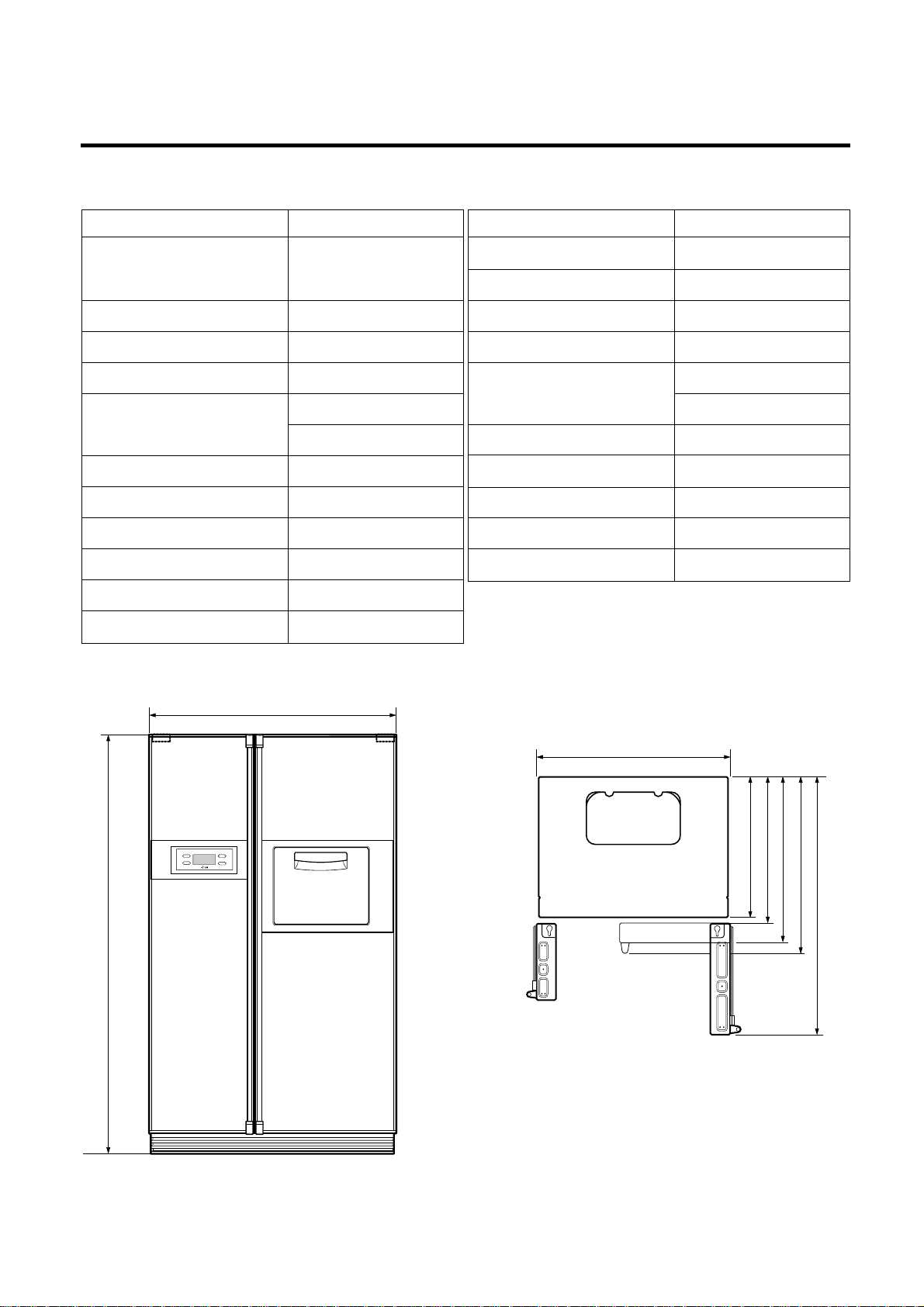
SPECIFICATIONS
- 4 -
ITEMS SPECIFICATIONS
DIMENSIONS 898(W)X847(D)X1756(H)mm
(35
1
/3X331/3X691/8 in.)
NET WEIGHT 151kg (332
7
/8 lbs.)
COOLING SYSTEM Fan Cooling
TEMPERATURE CONTROL Micom Control
DEFROSTING SYSTEM Full Automatic
Heater Defrost
INSULATION Cyclo-Pentane
COMPRESSOR P.T.C. Starting Type
EVAPORATOR Fin Tube Type
CONDENSER Wire Condenser
REFRIGERANT R134a (185g) (6
1
/2 oz.)
LUBRICATING OIL FREOL @15G (320 cc)
DRIER 1Ø0.83
ITEMS SPECIFICATIONS
CAPILLARY TUBE MOLECULAR SIEVE XH-7
FIRST DEFROST 4 - 5 Hours
DEFROST CYCLE 13 - 15 Hours
DEFROSTING DEVICE Heater, Sheath
Heater, L - Cord
ANTI SWEAT HEATER Dispenser Duct Door Heater
Dispenser Heater
Home Bar Heater
ANTI-FREEZING HEATER Water Tank Heater
Damper Heater
FREEZER LAMP 40W (1 EA)
REFRIGERATOR LAMP 40W (1 EA)
DISPENSER LAMP 15W (1 EA)
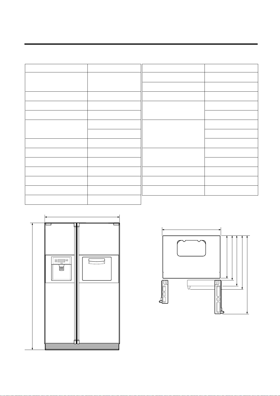
<Front View> <Plane View>
1. Ref No. : GR-P247
898 (351/3)
/8)
1
1756 (69
948 (373/8)
/8)
3
/8)
3
685 (27)
745 (29
796 (31
/3)
1
847 (33
1218.5 (48)
Page 5
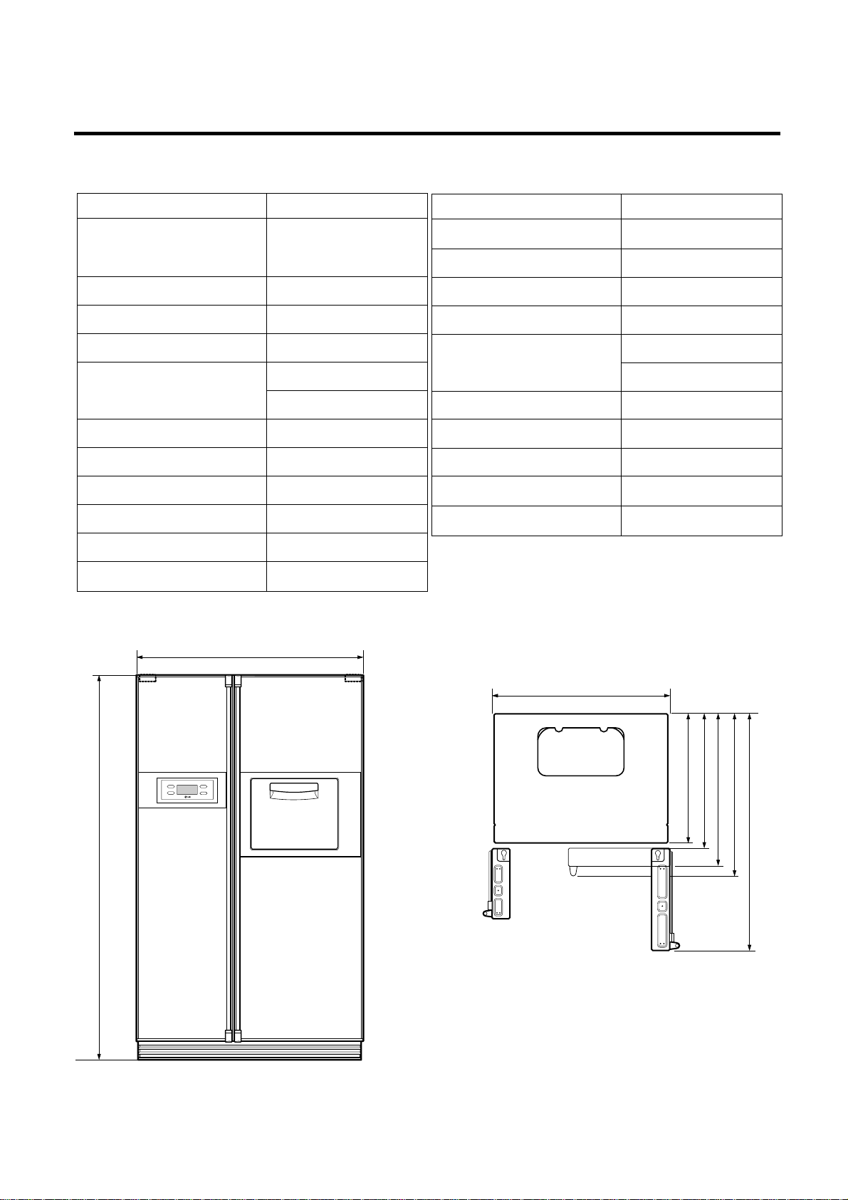
SPECIFICATIONS
- 5 -
ITEMS SPECIFICATIONS
DIMENSIONS 898(W)X762(D)X1756(H)mm
(35
1
/3X30X691/8 in.)
NET WEIGHT 146kg (321
7
/8 lbs.)
COOLING SYSTEM Fan Cooling
TEMPERATURE CONTROL Micom Control
DEFROSTING SYSTEM Full Automatic
Heater Defrost
INSULATION Cyclo-Pentane
COMPRESSOR P.T.C. Starting Type
EVAPORATOR Fin Tube Type
CONDENSER Wire Condenser
REFRIGERANT R134a (185g) (6
1
/2 oz.)
LUBRICATING OIL FREOL @15G (320 cc)
DRIER 1Ø0.83
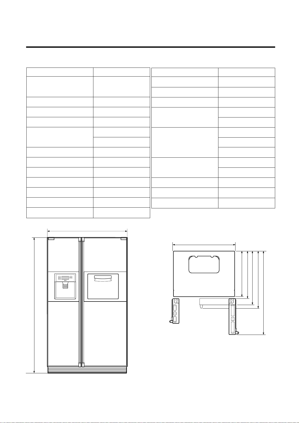
<Front View> <Plane View>
2. Ref No. : GR-P207
ITEMS SPECIFICATIONS
CAPILLARY TUBE MOLECULAR SIEVE XH-7
FIRST DEFROST 4 - 5 Hours
DEFROST CYCLE 13 - 15 Hours
DEFROSTING DEVICE Heater, Sheath
Heater, L - Cord
ANTI SWEAT HEATER Dispenser Duct Door Heater
Dispenser Heater
Home Bar Heater
ANTI-FREEZING HEATER Water Tank Heater
Damper Heater
FREEZER LAMP 40W (1 EA)
REFRIGERATOR LAMP 40W (1 EA)
DISPENSER LAMP 15W (1 EA)
898 (351/3)
/8)
1
1756 (69
948 (37
3
/8)
/8)
5
/8)
5
660 (26)
711 (28)
600 (23
762 (30)
1133.5 (44
Page 6

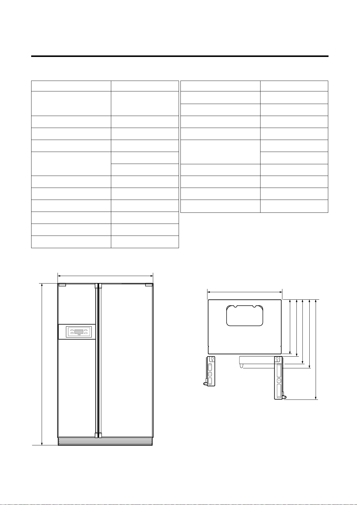
SPECIFICATIONS
- 6 -
ITEMS SPECIFICATIONS
DIMENSIONS 898(W)X847(D)X1756(H)mm
(35
1
/3X331/3X691/8 in.)
NET WEIGHT 145kg (319
2
/3 lbs.)
COOLING SYSTEM Fan Cooling
TEMPERATURE CONTROL Micom Control
DEFROSTING SYSTEM Full Automatic
Heater Defrost
INSULATION Cyclo-Pentane
COMPRESSOR P.T.C. Starting Type
EVAPORATOR Fin Tube Type
CONDENSER Wire Condenser
REFRIGERANT R134a (185g) (6
1
/2 oz.)
LUBRICATING OIL FREOL @15G (320 cc)
ITEMS SPECIFICATIONS
DRIER 1Ø0.83
CAPILLARY TUBE MOLECULAR SIEVE XH-7
FIRST DEFROST 4 - 5 Hours
DEFROST CYCLE 13 - 15 Hours
DEFROSTING DEVICE Heater, Sheath
Heater, L-Cord
ANTI SWEAT HEATER Dispenser Duct Door Heater
Dispenser Heater
ANTI-FREEZING HEATER Water Tank Heater
Damper Heater
FREEZER LAMP 40W (1 EA)
REFRIGERATOR LAMP 40W (1 EA)
DISPENSER LAMP 15W (1 EA)
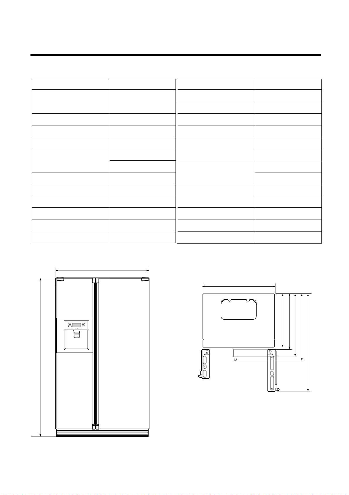
<Front View> <Plane View>
3. Ref No. : GR-L247
898 (351/3)
/8)
1
1756 (69
948 (37
3
/8)
/8)
3
/8)
3
/3)
1
685 (27)
745 (29
796 (31
847 (33
1218.5 (48)
Page 7
SPECIFICATIONS
- 7 -
ITEMS SPECIFICATIONS
DIMENSIONS 898(W)X762(D)X1756(H)mm
(35
1
/3X30X691/8 in.)
NET WEIGHT 140kg (308
1
/3 lbs.)
COOLING SYSTEM Fan Cooling
TEMPERATURE CONTROL Micom Control
DEFROSTING SYSTEM Full Automatic
Heater Defrost
INSULATION Cyclo-Pentane
COMPRESSOR P.T.C. Starting Type
EVAPORATOR Fin Tube Type
CONDENSER Wire Condenser
REFRIGERANT R134a (185g) (6
1
/2 oz.)
LUBRICATING OIL FREOL @15G (320 cc)
ITEMS SPECIFICATIONS
DRIER 1Ø0.83
CAPILLARY TUBE MOLECULAR SIEVE XH-7
FIRST DEFROST 4 - 5 Hours
DEFROST CYCLE 13 - 15 Hours
DEFROSTING DEVICE Heater, Sheath
Heater, L-Cord
ANTI SWEAT HEATER Dispenser Duct Door Heater
Dispenser Heater
ANTI-FREEZING HEATER Water Tank Heater
Damper Heater
FREEZER LAMP 40W (1 EA)
REFRIGERATOR LAMP 40W (1 EA)
DISPENSER LAMP 15W (1 EA)
<Front View> <Plane View>
4. Ref No. : GR-L207
898 (351/3)
/8)
1
1756 (69
948 (37
3
/8)
/8)
5
/8)
5
660 (26)
711 (28)
600 (23
762 (30)
1133.5 (44
Page 8
SPECIFICATIONS
- 8 -
ITEMS SPECIFICATIONS
DIMENSIONS 898(W)X847(D)X1756(H)mm
(35
1
/3X331/3X691/8 in.)
NET WEIGHT 142kg (313
1
/2 lbs.)
COOLING SYSTEM Fan Cooling
TEMPERATURE CONTROL Micom Control
DEFROSTING SYSTEM Full Automatic
Heater Defrost
INSULATION Cyclo-Pentane
COMPRESSOR P.T.C. Starting Type
EVAPORATOR Fin Tube Type
CONDENSER Wire Condenser
REFRIGERANT R134a (185g) (6
1
/2 oz.)
LUBRICATING OIL FREOL @15G (320 cc)
ITEMS SPECIFICATIONS
DRIER 1Ø0.83
CAPILLARY TUBE MOLECULAR SIEVE XH-7
FIRST DEFROST 4 - 5 Hours
DEFROST CYCLE 13 - 15 Hours
DEFROSTING DEVICE Heater, Sheath
Heater, L - Cord
ANTI SWEAT HEATER Home Bar Heater
ANTI-FREEZING HEATER Damper Heater
FREEZER LAMP 40W (1 EA)
REFRIGERATOR LAMP 40W (1 EA)
DISPENSER LAMP 15W (1 EA)
<Front View> <Plane View>
1. Ref No. : GR-C247
898 (351/3)
/8)
1
1756 (69
948 (37
3
/8)
/8)
3
/8)
3
/3)
1
685 (27)
745 (29
796 (31
847 (33
1218.5 (48)
Page 9
SPECIFICATIONS
- 9 -
ITEMS SPECIFICATIONS
DIMENSIONS 898(W)X762(D)X1756(H)mm
(35
1
/3X30X691/8 in.)
NET WEIGHT 137kg (302
2
/7 lbs.)
COOLING SYSTEM Fan Cooling
TEMPERATURE CONTROL Micom Control
DEFROSTING SYSTEM Full Automatic
Heater Defrost
INSULATION Cyclo-Pentane
COMPRESSOR P.T.C. Starting Type
EVAPORATOR Fin Tube Type
CONDENSER Wire Condenser
REFRIGERANT R134a (185g) (6
1
/2 oz.)
LUBRICATING OIL FREOL @15G (320 cc)
<Front View> <Plane View>
2. Ref No. : GR-C207
ITEMS SPECIFICATIONS
DRIER 1Ø0.83
CAPILLARY TUBE MOLECULAR SIEVE XH-7
FIRST DEFROST 4 - 5 Hours
DEFROST CYCLE 13 - 15 Hours
DEFROSTING DEVICE Heater, Sheath
Heater, L - Cord
ANTI SWEAT HEATER Home Bar Heater
ANTI-FREEZING HEATER Damper Heater
FREEZER LAMP 40W (1 EA)
REFRIGERATOR LAMP 40W (1 EA)
DISPENSER LAMP 15W (1 EA)
898 (351/3)
/8)
1
1756 (69
948 (37
3
/8)
/8)
5
/8)
711 (28)
762 (30)
5
660 (26)
600 (23
1133.5 (44
Page 10
SPECIFICATIONS
- 10 -
ITEMS SPECIFICATIONS
DIMENSIONS 898(W)X847(D)X1756(H)mm
(35
1
/3X331/3X691/8 in.)
NET WEIGHT 140kg (308
1
/3 lbs.)
COOLING SYSTEM Fan Cooling
TEMPERATURE CONTROL Micom Control
DEFROSTING SYSTEM Full Automatic
Heater Defrost
INSULATION Cyclo-Pentane
COMPRESSOR P.T.C. Starting Type
EVAPORATOR Fin Tube Type
CONDENSER Wire Condenser
REFRIGERANT R134a (185g) (6
1
/2 oz.)
LUBRICATING OIL FREOL @15G (320 cc)
ITEMS SPECIFICATIONS
DRIER 1Ø0.83
CAPILLARY TUBE MOLECULAR SIEVE XH-7
FIRST DEFROST 4 - 5 Hours
DEFROST CYCLE 13 - 15 Hours
DEFROSTING DEVICE Heater, Sheath
Heater, L-Cord
ANTI-FREEZING HEATER Damper Heater
FREEZER LAMP 40W (1 EA)
REFRIGERATOR LAMP 40W (1 EA)
DISPENSER LAMP 15W (1 EA)
<Front View> <Plane View>
3. Ref No. : GR-B247
898 (351/3)
/8)
1
1756 (69
948 (37
3
/8)
/8)
3
/8)
3
/3)
1
685 (27)
745 (29
796 (31
847 (33
1218.5 (48)
Page 11

SPECIFICATIONS
- 11 -
ITEMS SPECIFICATIONS
DIMENSIONS 898(W)X762(D)X1756(H)mm
(35
1
/3X30X691/8 in.)
NET WEIGHT 135kg (297
5
/8 lbs.)
COOLING SYSTEM Fan Cooling
TEMPERATURE CONTROL Micom Control
DEFROSTING SYSTEM Full Automatic
Heater Defrost
INSULATION Cyclo-Pentane
COMPRESSOR P.T.C. Starting Type
EVAPORATOR Fin Tube Type
CONDENSER Wire Condenser
REFRIGERANT R134a (185g) (6
1
/2 oz.)
LUBRICATING OIL FREOL @15G (320 cc)
ITEMS SPECIFICATIONS
DRIER 1Ø0.83
CAPILLARY TUBE MOLECULAR SIEVE XH-7
FIRST DEFROST 4 - 5 Hours
DEFROST CYCLE 13 - 15 Hours
DEFROSTING DEVICE Heater, Sheath
Heater, L-Cord
ANTI-FREEZING HEATER Damper Heater
FREEZER LAMP 40W (1 EA)
REFRIGERATOR LAMP 40W (1 EA)
DISPENSER LAMP 15W (1 EA)
<Front View> <Plane View>
4. Ref No. : GR-B207
898 (351/3)
/8)
1
1756 (69
948 (37
3
/8)
/8)
5
/8)
711 (28)
762 (30)
5
660 (26)
600 (23
1133.5 (44
Page 12
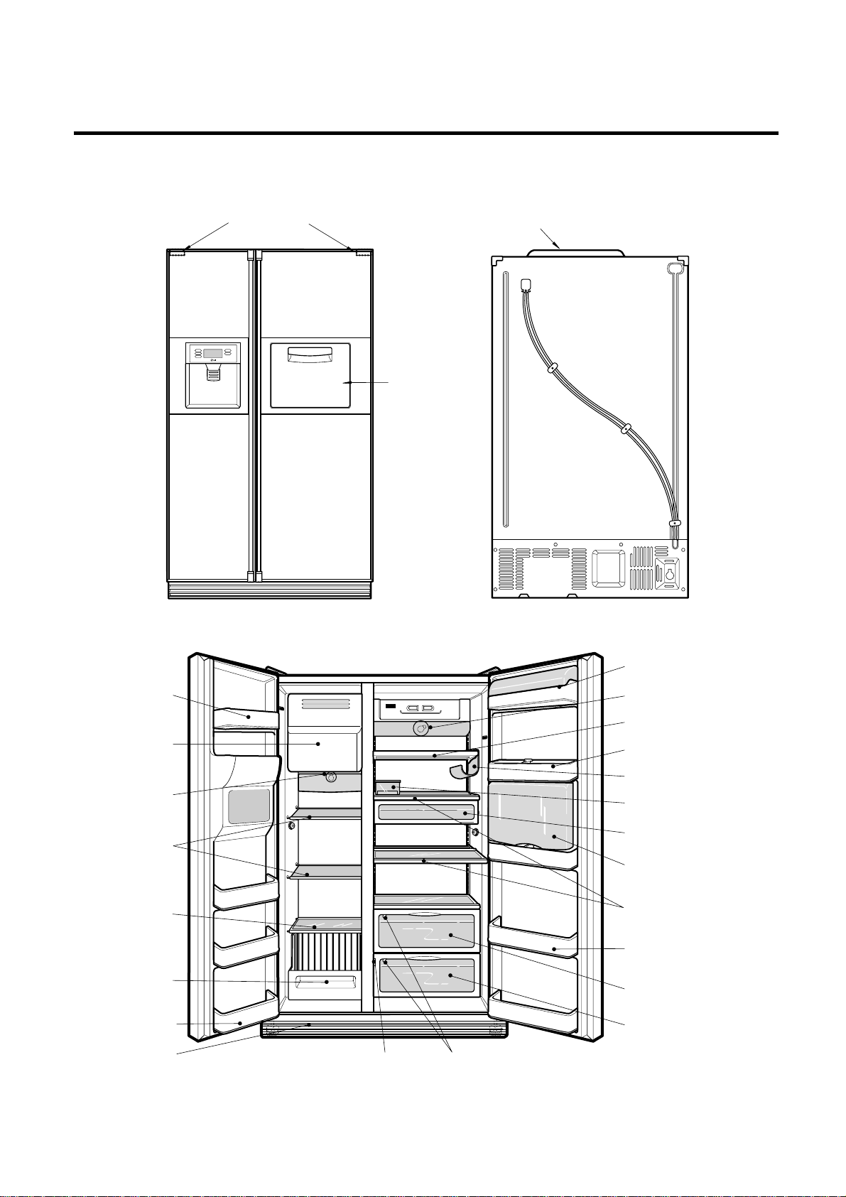
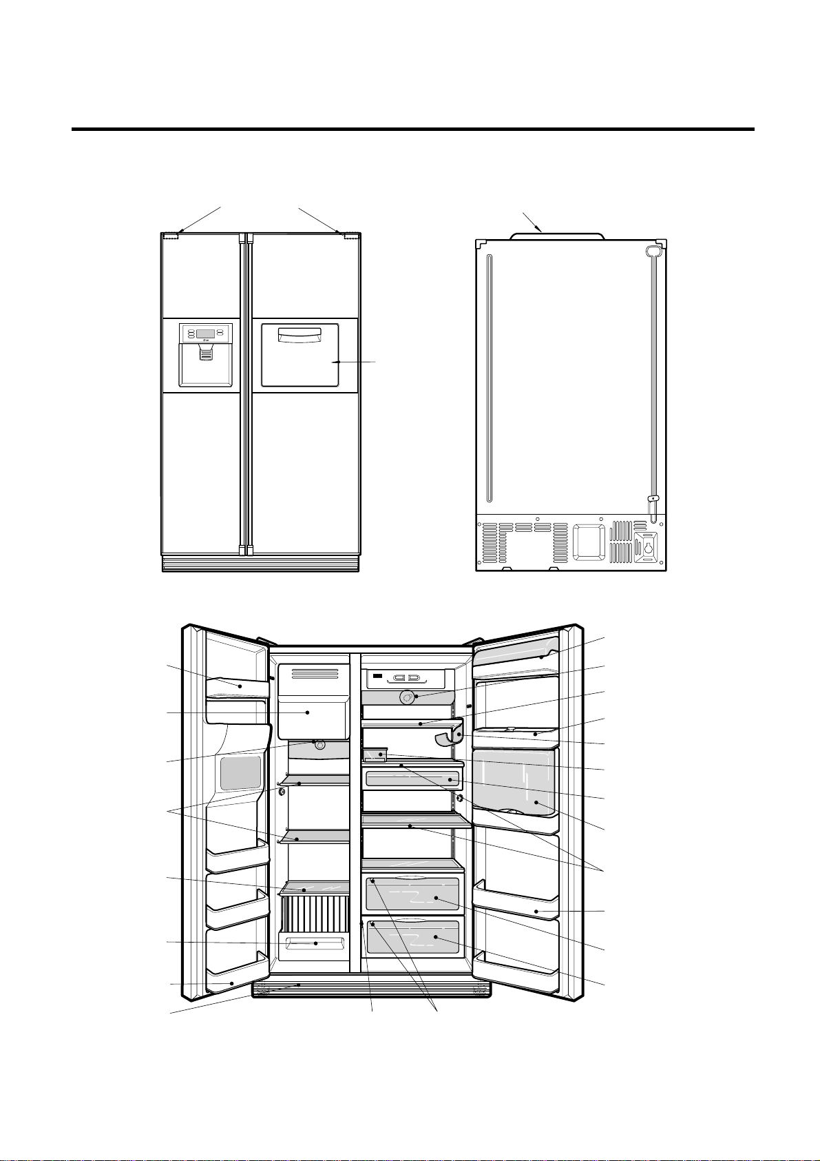
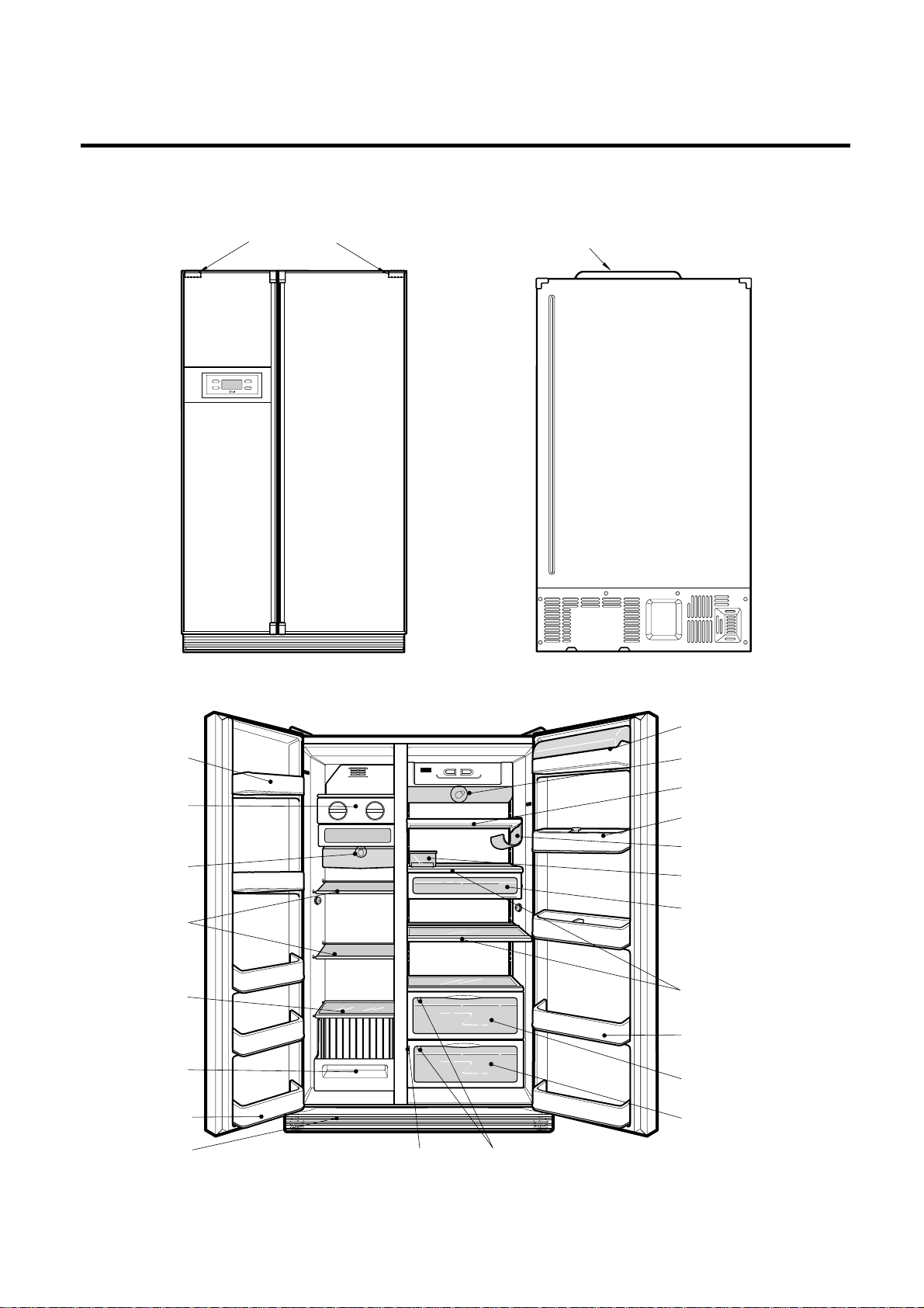
PARTS IDENTIFICATION
- 12 -
Conversion Switch
(Meats/Vegetables)
Humidity Switch
Lamp
Shelf
Egg Box
Snack Drawer
Vegetable Drawer
Vegetable
Drawer/Meat Drawer
Door Rack
Refreshment Center
(optional)
Shelf
Door Rack
Wine Holder (optional)
Lamp
Drawer
or Shelf
(optional)
Lower Cover
Door Rack
Drawer
Freezer
Compartment
Refrigerator
Compartment
Automatic
icemaker
Door Rack
Cover PWB
Cover Hinge
Home Bar
Dairy Product Corner
Shelf
(Steel/
Tempered
Glass)
1. Ref No. : GR-P247, GR-P207
Page 13
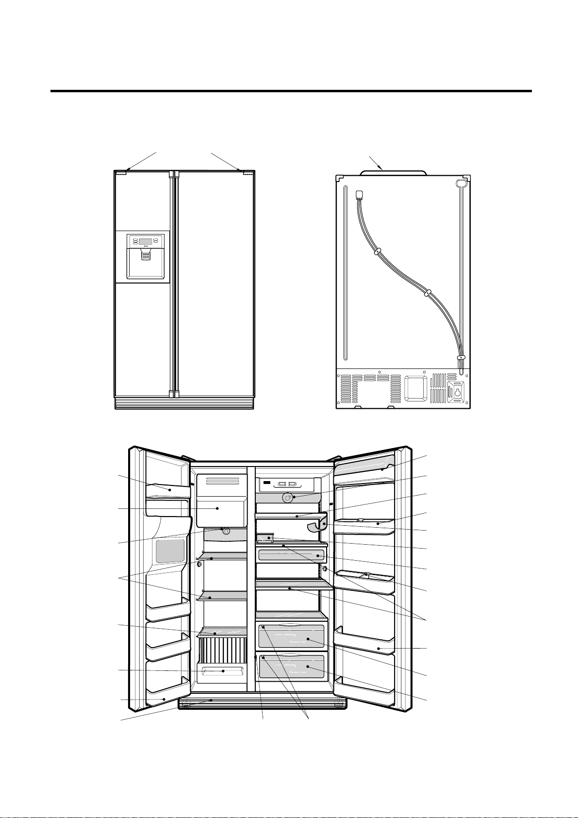
2. Ref No. : GR-P247, GR-P207
PARTS IDENTIFICATION
- 13 -
Conversion Switch
(Meats/Vegetables)
Humidity Switch
Lamp
Shelf
Egg Box
Snack Drawer
Vegetable Drawer
Vegetable
Drawer/Meat Drawer
Door Rack
Refreshment Center
(optional)
Shelf
Door Rack
Wine Holder (optional)
Lamp
Drawer
or Shelf
(optional)
Lower Cover
Door Rack
Drawer
Freezer
Compartment
Refrigerator
Compartment
Automatic
icemaker
Door Rack
Cover PWB
Cover Hinge
Home Bar
Dairy Product Corner
Shelf
(Steel/
Tempered
Glass)
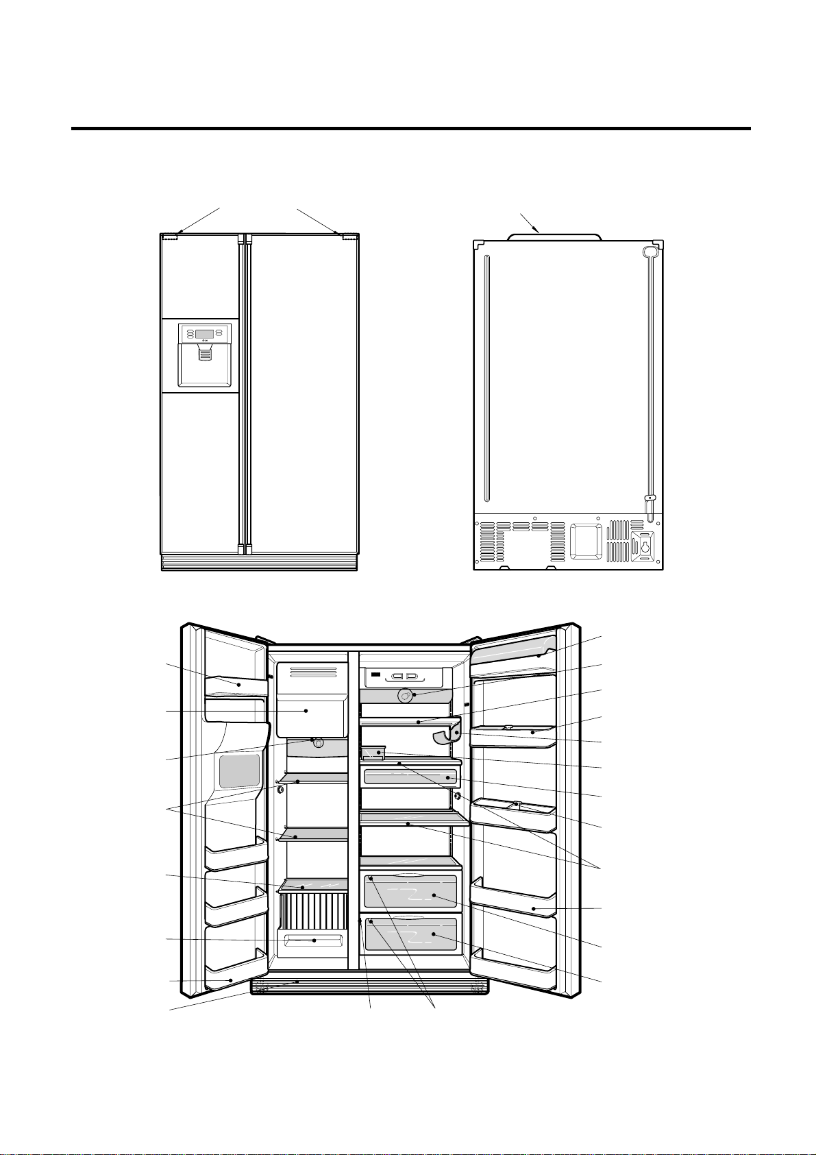
Page 14
PARTS IDENTIFICATION
- 14 -
Humidity Switch
Lamp
Shelf
Egg Box
Snack Drawer
Vegetable Drawer
Vegetable
Drawer/Meat Drawer
Door Rack
Guide Bottle
Shelf
Door Rack
Wine Holder (optional)
Lamp
Drawer
or Shelf
(optional)
Lower Cover
Door Rack
Drawer
Freezer
Compartment
Refrigerator
Compartment
Automatic
icemaker
Door Rack
Conversion Switch
(Meats/Vegetables)
Cover PWB
Cover Hinge
Dairy Product Corner
Shelf
(Steel/
Tempered
Glass)
3. Ref No. : GR-L247, GR-L207
Page 15
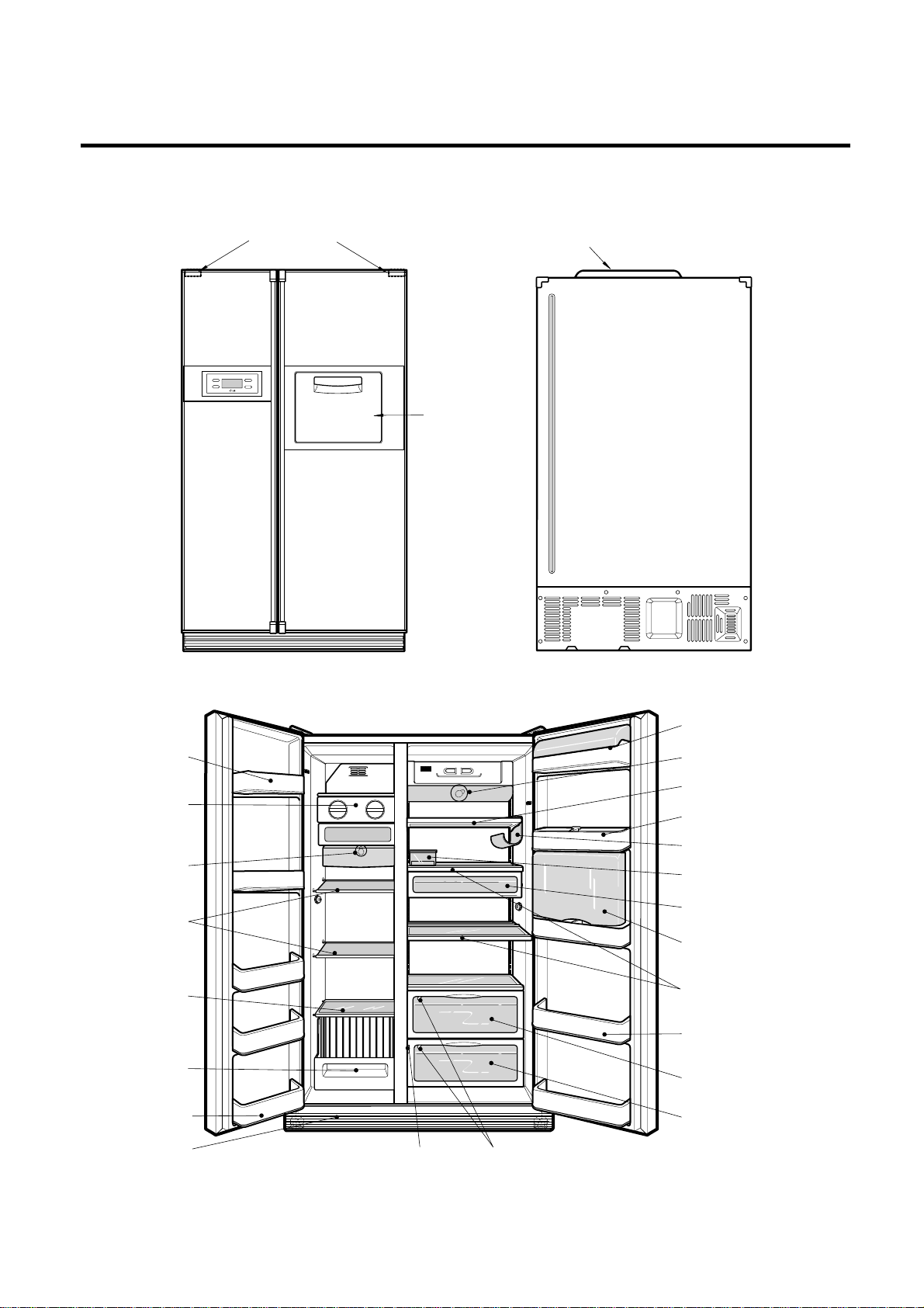
4. Ref No. : GR-L247, GR-L207
PARTS IDENTIFICATION
- 15 -
Conversion Switch
(Meats/Vegetables)
Humidity Switch
Lamp
Shelf
Egg Box
Snack Drawer
Vegetable Drawer
Vegetable
Drawer/Meat Drawer
Door Rack
Guide Bottle
Shelf
Door Rack
Wine Holder (optional)
Lamp
Drawer
or Shelf
(optional)
Lower Cover
Door Rack
Drawer
Freezer
Compartment
Refrigerator
Compartment
Automatic
icemaker
Door Rack
Cover PWB
Cover Hinge
Dairy Product Corner
Shelf
(Steel/
Tempered
Glass)
Page 16
PARTS IDENTIFICATION
- 16 -
Conversion Switch
(Meats/Vegetables)
Humidity Switch
Lamp
Shelf
Egg Box
Snack Drawer
Vegetable Drawer
Vegetable
Drawer/Meat Drawer
Door Rack
Refreshment Center
(optional)
Shelf
Door Rack
Wine Holder (optional)
Lamp
Icemaker
Drawer
or Shelf
(optional)
Lower Cover
Door Rack
Drawer
Freezer
Compartment
Refrigerator
Compartment
Door Rack
Cover PWB
Cover Hinge
Home Bar
Dairy Product Corner
Shelf
(Steel/
Tempered
Glass)
1. Ref No. : GR-C247, GR-C207
Page 17
PARTS IDENTIFICATION
- 17 -
Conversion Switch
(Meats/Vegetables)
Humidity Switch
Lamp
Shelf
Egg Box
Snack Drawer
Vegetable Drawer
Vegetable
Drawer/Meat Drawer
Door Rack
Shelf
Door Rack
Wine Holder (optional)
Lamp
Drawer
or Shelf
(optional)
Lower Cover
Door Rack
Drawer
Freezer
Compartment
Refrigerator
Compartment
Door Rack
Icemaker
Cover PWB
Cover Hinge
Dairy Product Corner
Shelf
(Steel/
Tempered
Glass)
3. Ref No. : GR-B247, GR-B207
Page 18
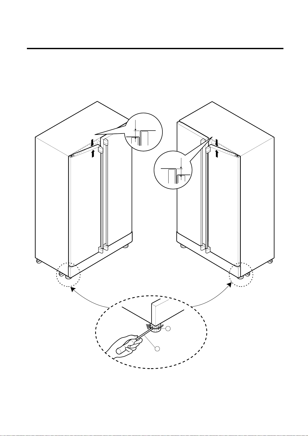
1. How to Adjust Door Height of Refrigerator
■ Make the refrigerator level first. (If the refrigerator is not installed on a flat floor, the height of freezer and refrigerator
door may not be the same.)
1. If the freezer door is lower than the refrigerator
door:
2. If the height of freezer door is higher than the
refrigerator door:
Insert a driver into the groove of adjusting screw
and rotate driver in arrow direction (clockwise) until the
refrigerator becomes horizontal.
Insert a driver into the groove of adjusting screw
and rotate driver in arrow direction (clockwise) until the
refrigerator becomes horizontal.
HOW TO INSTALL REFRIGERATOR
- 18 -
Adjusting
Screw
Driver
Height
Difference
Height
Difference
Height
Difference
Height
Difference
1
2
Page 19
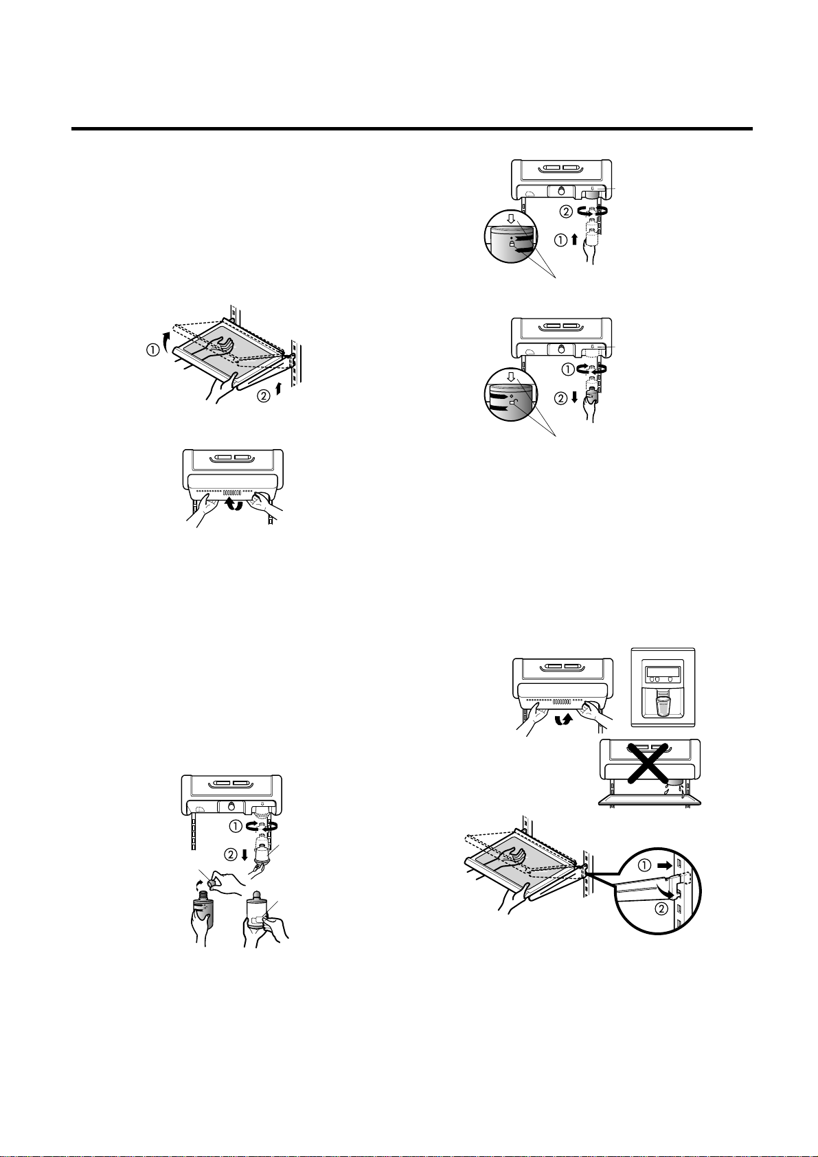
2. How to Install Water Pipe
■ Install Water Filter (Applicable to some models)
■ Before Installing water filter
1. Before installing the filter, take out the top shelf of the
refrigerator after tilting it to the direction () and lifting it
to the direction () and move it to the lower part.
2. Remove the lamp cover by pressing the protrusion
under the cover and pulling the cover to the front.
■ Installing water filter
1. Initial installation of water filter
Remove the filter substitute cap by turning it
counterclockwise () by 90 degrees and pulling it down.
Note : Keep it hardy to use it later when you do not use the
filter.
Remove the red cap from the filter and attach the
sticker. Insert the upper part of the filter () after
aligning with the guideline marked on the control box,
and fasten it by turning it clockwise by 90 degrees.
Note : Check that the guideline and the fastening
indication line are aligned.
2. Replacement of water filter
While holding the lower part of the filter, turn it
counterclockwise () by 90 degrees and pull it down.
Note : Check that the guideline and the loosening
indication line are aligned.
■ After installing water filter
Reassemble the lamp cover and the top shelf of the
refrigerator. To place the top shelf of the refrigerator, raise
the front part of the shelf a bit so that the hook of the shelf
is fit into the groove.
In order to clean the water filter system, drain water for
about 3 min.
Note : Then open the door of the refrigerator and check for
water drops on the shelf under the filter.
HOW TO INSTALL REFRIGERATOR
- 19 -
Control box
Aligning with the guide line
and the fastening indication line
Control box
Aligning with the guide line
and the loosening indication line
Removal
of red cap
Sticker
Substitute
cap
Page 20
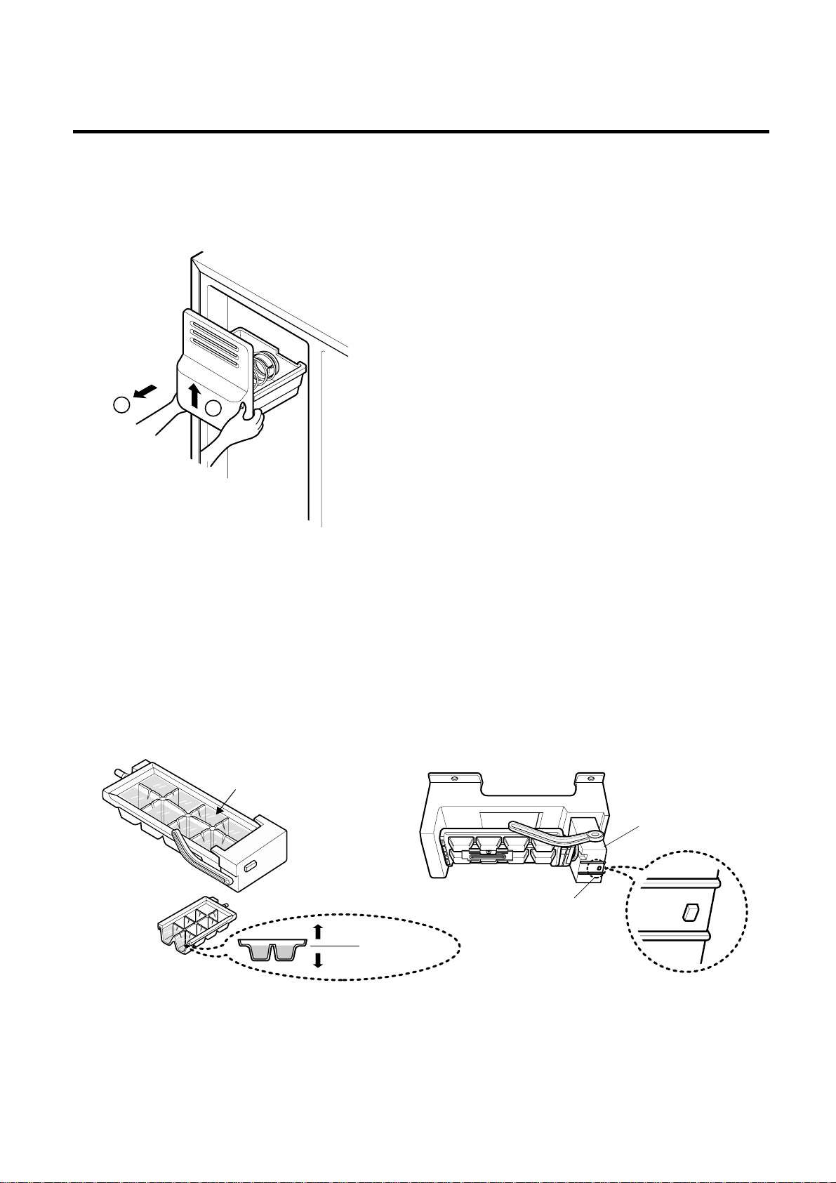
3. How to Control the Amount of Water Supplied to Icemaker.
3-1. Confirm the amount of water supplied to the icemaker.
1. Pull out the ice bin in the upper part of the freezer compartment.
Caution : • Do not put hands or tools into the chute to confirm
the operation of geared motor.
it may damage refrigerator or injure hands.)
• Check the operation of motor by listening to its noise.
2. Apply electricity after connecting water pipe.
1) Press test switch under the icemaker for two seconds as shown below.
2) The bell rings(ding~dong), ice tray rotates, and water comes out from the icemaker water tube.
3) The water shall be supplied two or three times into the tray. The amount of water supplied for each time is small.
Put a water container under the ice tray and press test switch.
4) When ice tray rotates, the water in it will spill. Collect the spilled water and throw it into the sink.
5) When ice tray has finished rotation, water comes out from the water tube. Confirm the amounts of water in the ice tray.
(refer to Figure. The optimum amount of water is 110cc[6.7in
3
])
* It is acceptable if the adjusted level of water is a bit smaller than optimum level.
HOW TO INSTALL REFRIGERATOR
- 20 -
2
1
Test Switch
Confirm the amount
of water
Icemaker
Too much
Too little
Optimum level
Page 21
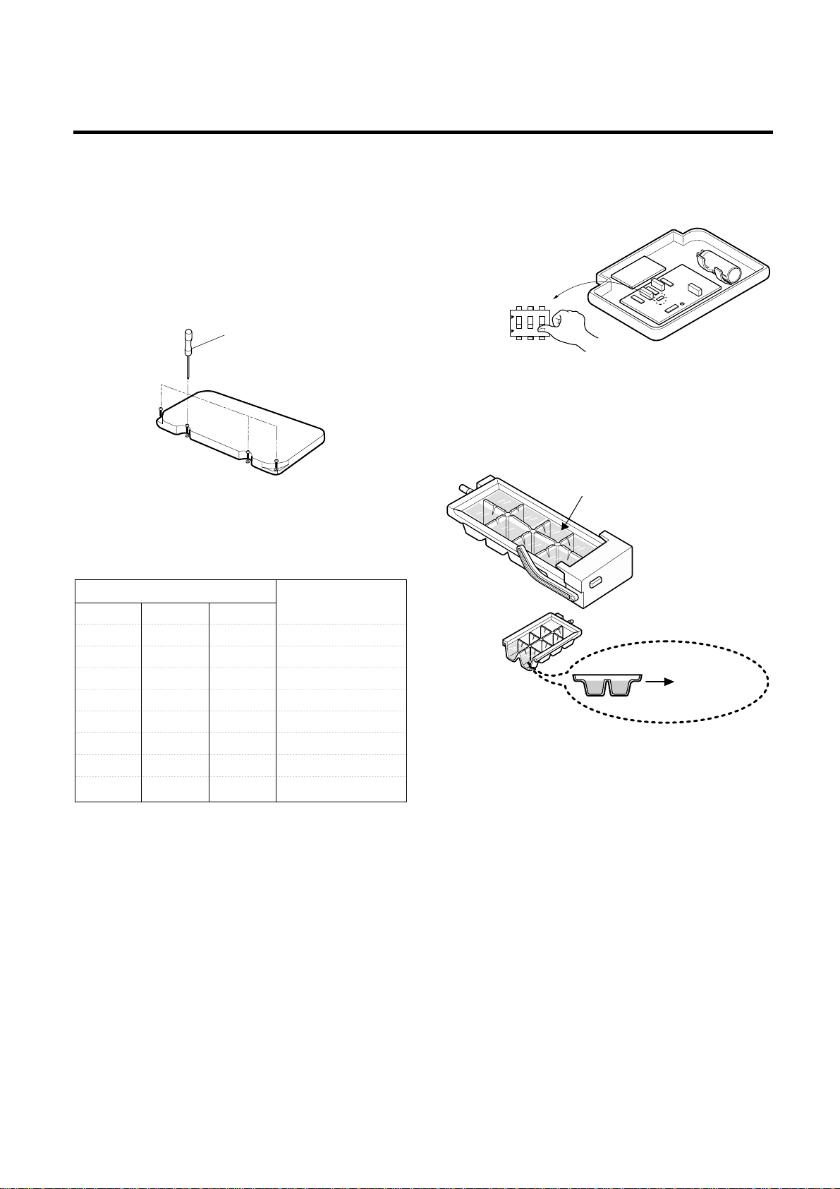
3-2. Control the amount of water supplied to the
icemaker.
Caution : • Please unplug the power cord from the wall
outlet and wait for more than three minutes
before disconnecting PWB cover as 310V is
applied in the control panel.
1. Disconnect PWB cover from the upper part of the
refrigerator.
2. Adjust the amount of water supplied by using the DIP
switches.
■ Water Supplying Time Control Option
1) The water supplying time is set at five seconds when the
refrigerator is delivered.
2) The amount of water supplied depends on the setting
time and water pressure (city water pressure).
3) If the ice cubes are too small, increase the water
supplying time. This happens when too little water is
supplied to the tray.
4) If the ice cubes stick together, decrease the water
supplying time. This happens when too much water is
supplied into the ice tray.
Caution : When adjusting the amount of water supplied,
adjust step by step. Otherwise the water may
spill over.
3. When adjustment of control switch for the amount of
water supplied is complete, check the level of water in
the ice tray.
HOW TO INSTALL REFRIGERATOR
- 21 -
SWITCH NO Water Supply
SWITCH1 SWITCH2 SWITCH3 Time
OFF OFF OFF 6.5 Sec.
ON OFF OFF 5.5 Sec.
OFF ON OFF 6 Sec.
ON ON OFF 7 Sec.
OFF OFF ON 7.5 Sec.
ON OFF ON 8 Sec.
OFF ON ON 9 Sec.
ON ON ON 10 Sec.
(+) Driver
Switch ON
Switch OFF
ON
1
23
Confirm the amount
of water
Optimum level
Page 22
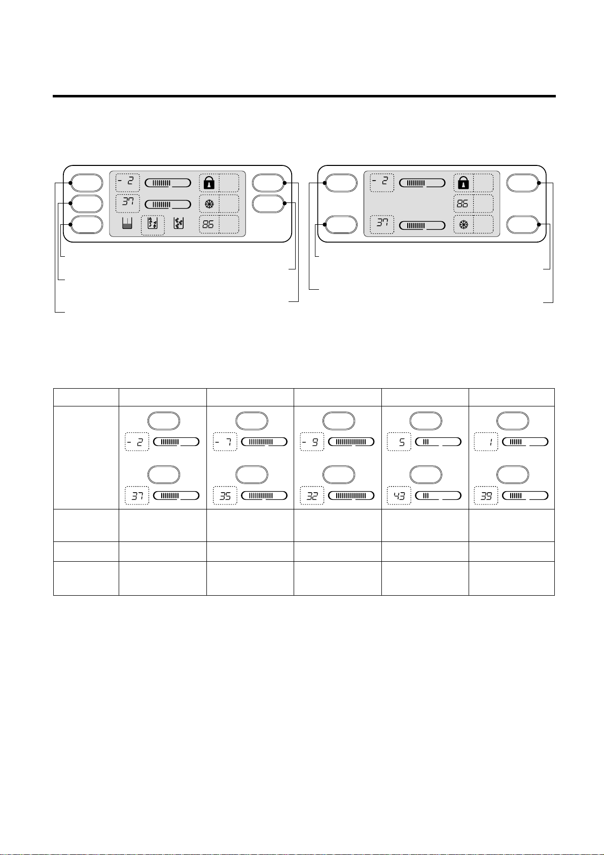
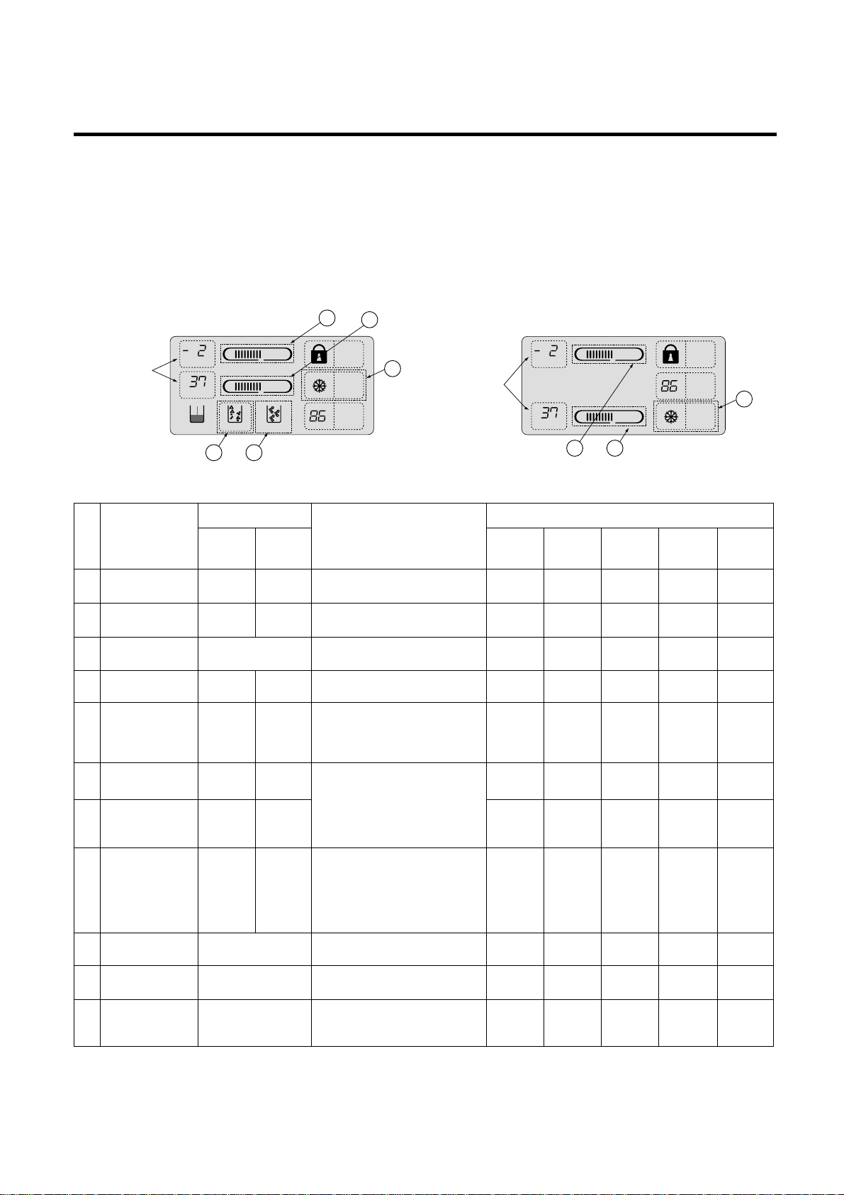
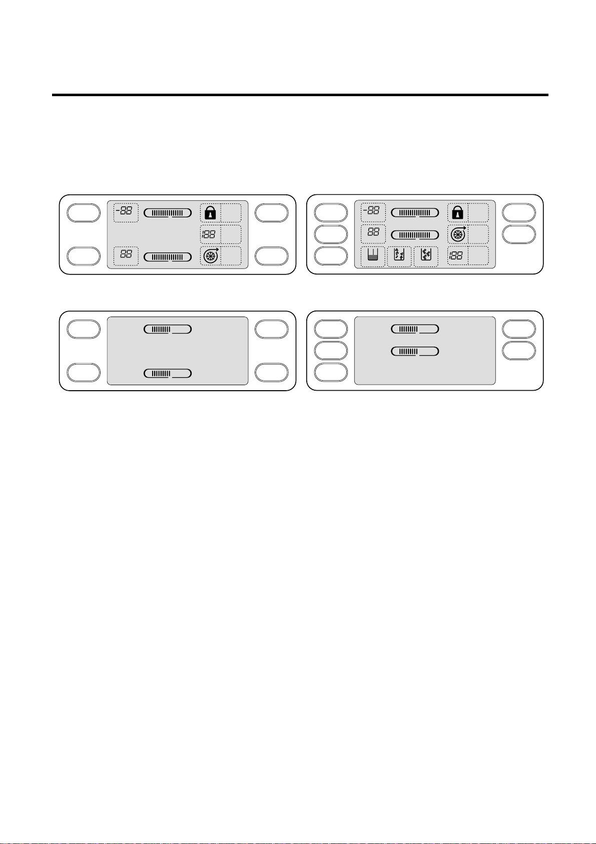
1. Monitor Panel
1-1. GR-P247, GR-P207, GR-L247, GR-L207 1-2. GR-C247, GR-C207, GR-B247, GR-B207
2. Description of Function
2-1-1. Funnction of Temperature Selection
* The temperature can vary ±3 °C depending on the load condition.
❉ Whenever pressing button, setting is repeated in the order of (Medium) ➝ (Medium Max) ➝ (Max) ➝ (Min) ➝
(Medium Min).
• The actual inner temperature varies depending on the food status, as the indicated setting temperature is a target
temperature, not actual temperature within refrigerator.
• Refrigeration function is weak in the initial time. Please adjust temperature as above after using refrigerator for minimum
2~3 days.
MICOM FUNCTION
- 22 -
MAXMIN
MAXMIN
LOCK
ON
OFF
ROOM
TEMP
°F
TEMP
TEMP
°F
°F
FRZ TEMP FRZ TEMP
REF TEMP
REF TEMP
DISPENSER
LOCK
SUPER FRZ
LOCK
SUPER FRZ
Dispenser selection button.
Temperature adjustment button
for refrigerator compartment.
Temperature adjustment button
for freezer compartment.
Super freezer.
Lock button.
Temperature adjustment button
for refrigerator compartment.
Temperature adjustment button
for freezer compartment.
Super freezer.
Lock button.
LOCK
ON
OFF
MAXMIN
MAXMIN
CRUSHED CUBED
WATER
TEMP
TEMP
ROOM
TEMP
°F
°F
°F
Division Power Initially On 1st Press 2st Press 3th Press 4th Press
Setting
temperature
Temperature
Control
Medium Medium Max Max Min Medium Min
Freezer Control
-19 °C [-2°F] -22 °C [-7°F] -23 °C [-9°F] -15 °C [5°F] -17 °C [1°F]
Refrigeration
3 °C [37°F] 2 °C [35°F] 0°C [32°F] 6 °C [43°F] 4 °C [39°F]
Control
FRZ TEMP
°F °F °F °F °F
REF TEMP
MAXMIN
FRZ TEMP
REF TEMP
FRZ TEMP
MAXMIN
REF TEMP
MAXMIN
FRZ TEMP
MAXMIN
REF TEMP
MAXMIN
°F °F °F °F °F
MAXMIN
MAXMIN
MAXMIN
FRZ TEMP
MAXMIN
REF TEMP
MAXMIN
Page 23
2-1-2. LCD Back Light Control
1. In order to easily view display status on the LCD, LCD Back Light is turned on for a minute in application of initial power,
for a minute in button manipulation and for a minute after closing time from opening time of door.
2. If pressing any display button once with the backlight turned off, buzzer rings and button function is not performed but
only backlight is turned on (If pressing the first button with the back light turned off, only back light ON function is
performed).
3. If pressing the special freezing button and the freezing temperature adjustment button for more than a second, the back
light is turned on and all the graphics of LCD are turned on. If releasing the button, the LCD graphic is displayed in the
previous status and the back light is turned off (check LCD graphic and back light ON/OFF status).
2-1-3. Outside temperature display function
1. Outside temperature sensor at the left U of refrigerator senses ambient temperature and displays the outside temperature
in the left side of Outside temperature text on the LCD of the display part.
2. Ambient temperature is displayed up to -9°C[16°F] ~ 49°C[120°F] and displayed as Lo for less than -10°C[14°F] and as
HI for more than 50°C[122°F]. If the ambient temperature sensor fails, it is displayed as Er.
3. Since display temperature of outside temperature is temperature sensed by the ambient sensor in the hinge U of the
freezing room, it may differ from the outside temperature display of other household electrical appliances.
2-1-4. Lock function (display button lock)
1. In power application of refrigerator, the only Release text is turned on at the right side of lock graphic of LCD with the lock
release status.
2. If desiring to lock the display status and pressing the lock/release button once, Release text is turned off at the right side
of lock graphic of LCD and Lock text is turned on with lock status.
3. The only buzzer sound rings and function is not performed even if pressing display button other than lock/release key in
the lock status.
4. If desiring to release the lock status and pressing the lock/release button once, Lock text is turned off at the right side of
lock graphic of LCD and Release text is turned on with lock release status.
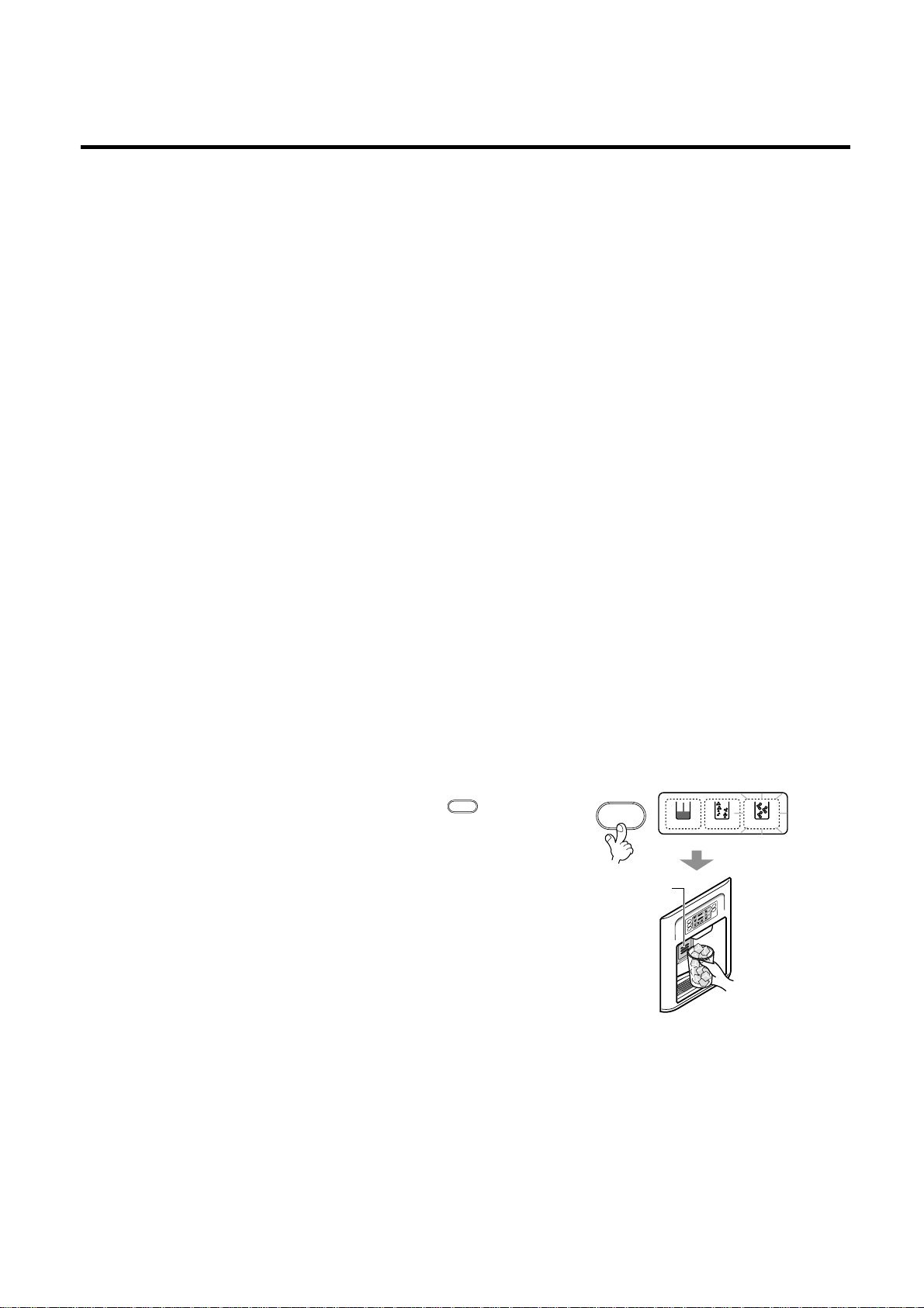
2-2. Dispenser use selection
You can select water or ice.
❉ Please select water, slice ice and square ice by pressing
button as you desire.
❉ Please press the push button lightly by catching and pushing in cup.
• The border line is indicated for the selected function.
• Tak! sounds if 5 seconds pass after ice comes out.
It is sound that the outlet of ice is closed.
REFERENCE : Please wait for 2-3 seconds in order to take final ice
slices or drops of water when taking out cup from the
pressing switches after taking ice or water.
2-3. Automatic icemaker
• The automatic icemaker can make 8 pieces of ice at a time, up to 10 times a day, for a total of 80 pieces per day. This
quantity may vary, affected by ice usage, ambient temperature, frequency of door opening, etc.
• Ice making stops when the ice storage bin is full.
• If you don’t want to use automatic icemaker, set the icemaker power switch OFF.
If you want to use automatic icemaker again, set the icemaker power switch ON.
NOTE : It is normal that a noise is produced when ice made is dropped into the ice storage bin.
MICOM FUNCTION
- 23 -
DISPENSER
CRUSHED CUBED
WATER
M
A
X
M
I
N
M
A
X
M
I
N
Pressing
Switch
DISPENSER
Page 24
2-4. When icemaker does not operate smoothly
Ice is lumped together
• When ice is lumped together, take the lumps out of the ice storage bin, break them into small pieces, and then place them
into the ice storage bin again.
• When the icemaker produces too small or lumpy ice, the amount of water supplied to the icemaker needs to adjusted.
Contact the service center.
✻ If ice is not used frequently, it may lump together.
Power failure
• Ice may drop into the freezer compartment. Take the ice storage bin out and discard all the ice dry the bin and replace it.
After the machine is powered again, crushed ice will be automatically selected.
The unit is newly installed
• It takes about 12 hours for a newly installed refrigerator to begin making ice.
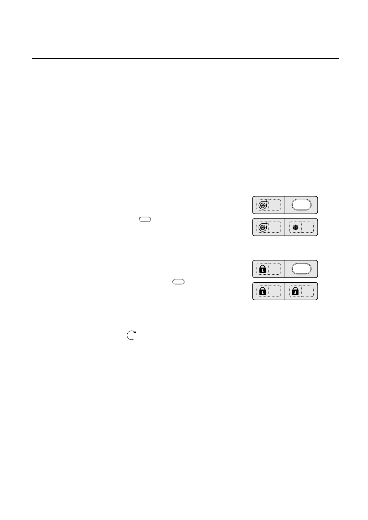
2-5. Super freezer
Please select this function for prompt freezer.
• On or Off is repeated whenever pressing button.
• The arrow mark graphic remains at the On status after flickering 4 times when
selecting Special Refrigeration On.
• Super freezer function automatically turns off if a fixed time passes.
2-6. Lock
This button stops operation of different button.
• Locking or Release is repeated whenever pressing the .
• Pressing the other button when selecting ‘LOCK’, the button does not operate.
2-7. Special freezing
1. Special freezing is function to improve cooling speed of the freezing room by consecutively operating compressors and
freezing room fan. If pressing the special freezing button, Turn Off text of the LCD panel is turned off and Turn On is
immediately turned on and Arrow ( ) graphic is turned on after flickering once.
2. Special freezing is cycled in order of Selection/ Release (Turn On / Turn Off) whenever pressing the selection button.
3. Special freezing is released if power failure occurs and then returns to the original status.
4. Temperature setting is not changed even if selecting the special freezing.
5. The change of temperature setting at the freezing room or the cold storage room is allowed with special freezing selected
and processed.
6. The cold storage room operates the status currently set with special freezing selected and processed.
7. If selecting the special freezing, the special freezing function is released after continuously operating compressor and
freezing room fan.
8. If frost removal starting time is arrived during special freezing, special freezing operation is done only for the remaining
time after completion of frost removal when the special freezing operation time passes 90 minutes. If passing 90 minutes,
special freezing operation is done only for 2 hours after completion of frost removal.
9. If pressing special freezing button during frost removal, the special freezing LCD is turned on but if pressing the special
freezing, compressor operates after the remaining time has passed.
10. If selecting special freezing within 7 minutes (delay for 7 minutes of compressor) after the compressor stops,
compressor operates after the remaining time has passed.
11. The freezing room fan motor operates at the high speed of RPM during operation of special freezing.
MICOM FUNCTION
- 24 -
Ex) In selecting
On
Ex) In selecting
Off
SUPER FRZ
ON
OFF
ON
OFF
Ex) In selecting
LOCK
Ex) In selecting
LOCK again
LOCK
LOCK
LOCK
LOCK
SUPER FRZ
Page 25
2-8. Control of variable type of freezer compartment fan
1. To increase cooling speed and load response speed, the MICOM variably controls freezing room fan motor at the high
speed of RPM and standard RPM.
2. MICOM only operates in the input of initial power or special freezing operation or load response operation for the high
speed of RPM and operates in the standard RPM in other general operation.
3. If opening doors of freezing / cold storage room or home bar while fan motor in the freezing room operates, the freezing
room fan motor normally operates (If being operated in the high speed of RPM, it converts operation to the standard
RPM). However, if opening doors of freezing room or home bar, the freezing room fan motor stops.
4. As for monitoring of BLDC fan motor error in the freezing room, MICOM immediately stops the fan motor by determining
that the BLDC fan motor is locked or poor if there would be position signal for more than 65 seconds at the BLDC motor.
Then it displays failure (refer to failure diagnosis function table) at the display part of refrigerator, performs re-operation in
the cycle of 30 minutes. If normal operation is performed, poor status is released and refrigerator returns to the initial
status (reset).
2-9. Control of M/C room fan motor
1. The M/C room fan motor performs ON/OFF control by linking with the COMP.
2. It controls at the single RPM without varying RPM.
3. Failure sensing method is same as freezing fan motor (refer to failure diagnosis function table for failure display).
2-10. Door opening alarm
1. Buzzer generates alarm sound if doors are not closed even when more than a minute consecutively has passed with
doors of freezing / cold storage room or home bar opened.
2. Buzzer rings three times in the interval of half second after the first one-minute has passed after doors are opened and
then repeats three times of On/Off alarm in the cycle of every 30 seconds.
3. If the doors of the freezer or home bar are closed during door open alarm, alarm is immediately released.
2-11. Ringing of button selection buzzer
1. If you press the front display button, the Ding sound.
2-12. Ringing of compulsory operation, compulsory frost removal buzzer
1. If you press the test button on the Main PCB, the Phi sounds.
2. In selecting compulsory operation, alarm sound is repeated and completed in the cycle of On for 0.2 second and Off for
1.8 second three times.
3. In selecting compulsory frost removal, alarm sound is repeated and completed in the cycle of On for 0.2 second , Off for
0.2 second, On for 0.2 second and Off for 1.4 second three times.
MICOM FUNCTION
- 25 -
Any Door
BUZZER
Closing
Opening
Within
a minute
A minute
30
seconds30seconds30seconds
Opening
Closing Closing
3 Times 3 Times 3 Times 3 T imes
Page 26
2-13. Frost removal function
1. Frost removal is performed whenever total operation time of compressor becomes 7 ~ 71/2 hour.
2. In providing initial power (or returning power failure), frost removal starts whenever total operation time of compressor
becomes 4 ~ 4
1
/2 hour.
3. Frost removal is completed if temperature of a frost removal sensor becomes more than 5°C[41°F] after starting frost
removal. Poor frost removal is not displaced if it does not arrive at 5°C[41°F] even if two hours have passed after starting
frost removal.
4. No removal is done if frost removal sensor becomes poor (snapping or short-circuit).
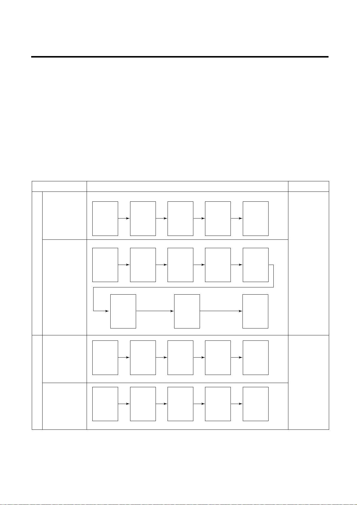
2-14. Sequential operation of built-in product
Built-in products such as compressor, frost removal heater, freezer fan, cooling fan and step motor damper are operated
sequentially as shown below to prevent noise and damage from power surges that occur when all parts are powered up at
once.
MICOM FUNCTION
- 26 -
Function Load Operation Sequence Remark
In applying Initial power TEST MODE
When temperature
of a frost removal
sensor becomes
more than 45°C
[77°F]
If error occurs
during operation,
initial operation is
not done.
If pressing switch
once more in the
test mode 2 or
temperature of a
frost removal
sensor is more
than 5°C[41°F], it
immediately
returns to the test
mode for initial
operation
(Compressor
operates after
7 minutes).
When
temperature of a
frost removal
sensor becomes
less than 45°C
[77°F]
Test mode 1
(Compulsory
function)
Test mode 2
(Compulsory frost
removal)
POWER
ON
COMP
ON
COMP
ON
STEP
MOTOR
DAMPER
ON
STEP
MOTOR
DAMPER
OPEN
STEP
MOTOR
DAMPER
CLOSE
HOME
BAR
HEATER
ON
POWER
ON
FROST
REMOVAL
HEATER
ON
HOME
BAR
HEATER
OFF
HOME
BAR
HEATER
ON
TEST
S/W
(Press
Once)
COMP
ON
TEST
S/W
(Press
2 times)
COMP
OFF
1/2
sec.
1/4
sec.
1/4
sec.
1/4
sec.
1/2
sec.
8
sec.
1/4
sec.
5
sec.
FROST
REMOVAL
HEATER
OFF
WATER
SUPPLY
&
DISPENSE
HEATER
ON
5
sec.
1/4
sec.
1/4
sec.
1/4
sec.
1/4
sec.
1/4
sec.
1/4
sec.
1/4
sec.
5.6
sec.
OTHER
LOAD
OFF
F-FAN
&
C-FAN
ON
F-FAN
&
C-FAN
ON
F-FAN
&
C-FAN
ON
F-FAN
&
C-FAN
OFF
FROST
REMOVAL
HEATER
ON
Page 27
2-15. Failure Diagnosis Function
1. Failure diagnosis function is to facilitate service when a failure occurs affecting performance of product during use of
product.
2. In occurrence of failure, pressing the function adjustment button does not perform function and only alarm sound (Ding~) rings.
3. If nonconforming matters occurred are released during display of failure code, MICOM returns to the original state (Reset).
4. Failure code is displayed on the display part of setting temperature for the freezing room and the display part of setting
temperature for the cold storage room of LCD, which are placed at the display part of a refrigerator. All the LCD graphics
other than a failure code are turned off.
✽ In display of the failure mode, all LCDs of setting temperature for freezing/ setting temperature for cold storage are turned
off (excluding Note1 and Note2).
MICOM FUNCTION
- 27 -
OFF
MAXMIN
MAXMIN
CRUSHED CUBED
WATER
OFF
MAXMIN
MAXMIN
Failure Code
display Part
High quality type
(GR-P207, L207, P247, L247)
Failure Code
display Part
Basic type
GR-C247, B247, C207, B207)
C
A
B
E
C
D
A B
ROOM
TEMP
ROOM
TEMP
TEMP
TEMP
°F
°F
°F
TEMP
TEMP
°F
°F
°F
●● : Normal Operation
1
2
3
4
5
6
7
8
9
10
11
Er FS
Er RS
Setting temperature
display (Note 2)
Er DS
Er dH
Er FF
Er CF
Er CO
Setting temperature
display (Note 1)
Setting temperature
display (Note 2)
Setting temperature
display (Note 2)
Failure code display part
Setting
temperature
for freezing
Setting
temperature for
cold storage
No. Item
Contents of failure
Freezer
Fan
Compressor
Stepping
motor damper
Defrost
Heater
M/C room
Fan
Product operation status in failure
Failure of freezer
sensor
Failure of refrigerator
sensor 1
Failure of refrigerator
sensor 2
Failure of frost
removal sensor
Poor of frost
removal
Failure of BLDC FAN
at freezing room
Failure of BLDC FAN
at machine room
Failure of
Communication
Failure of
Outside Sensor
Failure of ice
removal sensor
Failure of
icemaker unit
Snapping or short-circuit of
freezer sensor
Snapping or short-circuit of
refrigerator sensor 1
Snapping or short-circuit of
refrigerator sensor 2
Snapping or short-circuit of frost
removal sensor
Snapping of frost removal heater
or temperature fuse, pull-out of
connector (indicated minimum 4
hours after failure occurs)
Poor motor, hooking of wires to
fan. Contact of structures to Fan.
Snapping or short-circuit of L/wire
(if there is no fan motor signal for
more than 60 seconds in
operation of fan motor
Connection between main PCB
and display PCB. Snapping or
short-circuit of L/wire.
Transmission between main PCB
and display PCB. Poor TR and
receiving part.
Snapping or short-circuit of outside
temperature perceiving sensor
Snapping or short-circuit of icemaking sensor
Poor motor or Hall IC within ice-maker
unit. Snapping or short-circuit of
L/Wire. Poor main PCB drive circuit.
Standard
RPM
Standard
RPM
Standard
RPM
Standard
RPM
Standard
RPM
OFF (check every
30 minutes)
Standard
RPM
Standard
RPM
●●
●●
●●
●●
●●
●●
●●
●●
●●
OFF (check
every 30 minutes)
●●
●●
●●
●●
ON for 15minutes
OFF for 15minutes
●●
●●
●●
●●
●●
●●
●●
●●
●●
●●
●●
●●
●●
No frost
removal
●●
●●
●●
●●
●●
●●
●●
●●
Open for 10munutes,
closing for 15 minutes
●●
●●
●●
●●
●●
●●
●●
●●
●●
Page 28
Note1) In error of outside sensor, setting temperature for freezing/ cold storage is normally displayed and indicated Er on
the outside temperature display part (normally displayed except for the outside temperature display part).
Note2) Nonconforming contents of poor R2 sensor, Icemaker-sensor and icemaker kit are displayed in LCD check, not
indicated on the failure display part (when pressing freezing temperature adjustment button and special freezing
button for a second or more).
Cold storage sensor 2 Normal : (C) Part LCD graphic- ON
(middle partition) Abnormal: Only (C) Part LCD graphic-OFF
Icemaker sensor
Normal: (D) Part LCD graphic-ON
Abnormal: Only (D) Part LCD graphic-ON
Icemaker Unit
Normal: (E) Part LCD graphic-ON
Abnormal : Only (E) Part LCD graphic-ON
2-16. Test Function
1. The purpose of test function is to check function of the PWB and product and to search for the failure part at the failure
status.
2. Test button is placed on the main PCB of refrigerator (test switch), and the test mode will be finished after maximum 2
hours regardless of test mode and then is reset to the normal status.
3. Function adjustment button is not perceived during performance of test mode but only warning sounds ring.
4. In finishing test mode, always pull the power cord out and then plug-in it again for the normal state.
5. If nonconforming contents such as sensor failure are found during performance of test mode, release the test mode and
display the failure code.
6. If you press the test button during a failure code display, test mode will not be activated.
MICOM FUNCTION
- 28 -
Other LCD graphics - ON
Test 1
Test 2
Normal
Conditions
Mode Manipulation Content Remarks
Press TEST switch once
Press TEST switch once at
TEST1 condition.
Press TEST switch once at
TEST2 condition.
1. Continuous operation of compressor
2. Continuous operation of freezing room fan
(high speed RPM) and M/C room fan
3. Frost removal heater OFF
4. Full opening status (baffle opened) status of
electronic step motor damper
5. All display LCD graphics - ON.
1. Compressor OFF
2. Freezing room fan and M/C room fan is
turned off.
3. Frost removal heater ON
4. Full closing status (baffle closed) status of
electronic step motor damper
5. All display LCD graphics - OFF
( (A) Medium status. (B) Medium status.
Only LCD is turned on)
Return to the initial status.
Freezing room fan is
turned off in door open.
Compressor is operated
after 7 minutes.
Page 29
✻ LCD check function: If simultaneously pressing special freezing button and cold temperature adjustment button for a
second, a back light is turned on and all display LCD graphics on. If releasing the button, the LCD
graphic displays the previous status, the back light is turned off (LCD graphic and back light ON/OFF
check).
2-17. Function of dispenser and water dispenser built-in
1. This is function allowing ice and water to come outside without opening door.
2. If pressing the dispenser switch (bushing button) after selecting ice (cube ice, crushed ice) or water, ice and water
equivalent to each come out. However, the duct doors are opened by electrical solenoid valve (Duct Door Solenoid) if
pressing the press switch in case of selecting ICE. If pressing the dispenser press switch and then detaching the hands,
the duct door is closed after it is opened for 5 seconds.
3. Function allowing ice and water to come stops if freezing room doors are opened.
4. If there is no Off signal even when 3 minutes have passed while pressing the dispenser press switch after selecting ice
(cube ice, crushed ice) or water, geared motor and solenoid (Cube, Water) is automatically turned off. However, the
solenoid (duct door) is stop 5 seconds after Off (to prevent short-circuit of a coil due to overheat of solenoid).
5. Dispenser Lamp On/Off function
Lamp on the dispenser part is turned on if pressing the dispenser press switch after selecting ice (cube ice, crushed ice)
or water. If detaching the hands, it is turned off.
6. Selection function of water/crushed/ cube ice
1) This is function to allow selection of water/crushed/ cube ice function depending on user’s selection. Display and
selection is done if pressing the dispenser selection button.
2) In the initial Power On, cube ice is automatically selected.
3) In selecting cube ice, geared motor is operated so that crushed ice can be supplied outside if pressing the press switch
when ice is formed in the ice storage container (Ice Bin).
4) In selecting cube ice, geared motor is operated so that cube ice can be supplied outside if pressing the press switch
when ice is formed in the ice storage container (Ice Bin).
7. Water dispenser function
1) LCD is displayed for selection if user selects water at the function adjustment part.
2) Water dispenser function is a type directly connected to a water pipe. The water solenoid valve built-in at the right side
of the M/C room is opened so that water can be supplied if selecting Water from the function adjustment part and then
pressing the press switch.
MICOM FUNCTION
- 29 -
<TEST MODE 1 STATUS LCD>
<TEST MODE 2 STATUS LCD>
LOCKFRZ TEMP
REF TEMP
SUPER FRZ
MAXMIN
MAXMIN
LOCK
ON
OFF
LOCK
FRZ TEMP
FRZ TEMP
REF TEMP
REF TEMP
DISPENSER
LOCK
SUPER FRZ
SUPER FRZ
MAXMIN
MAXMIN
MAXMIN
MAXMIN
FRZ TEMP
REF TEMP
DISPENSER
LOCK
SUPER FRZ
LOCK
ON
OFF
MAXMIN
MAXMIN
CRUSHED CUBED
WATER
TEMP
°C
TEMP
ROOM
TEMP
TEMP
TEMP
ROOM
TEMP
°C
°C
°F
°F
°F
°C
°C
°F
°F
°C
°F
Page 30
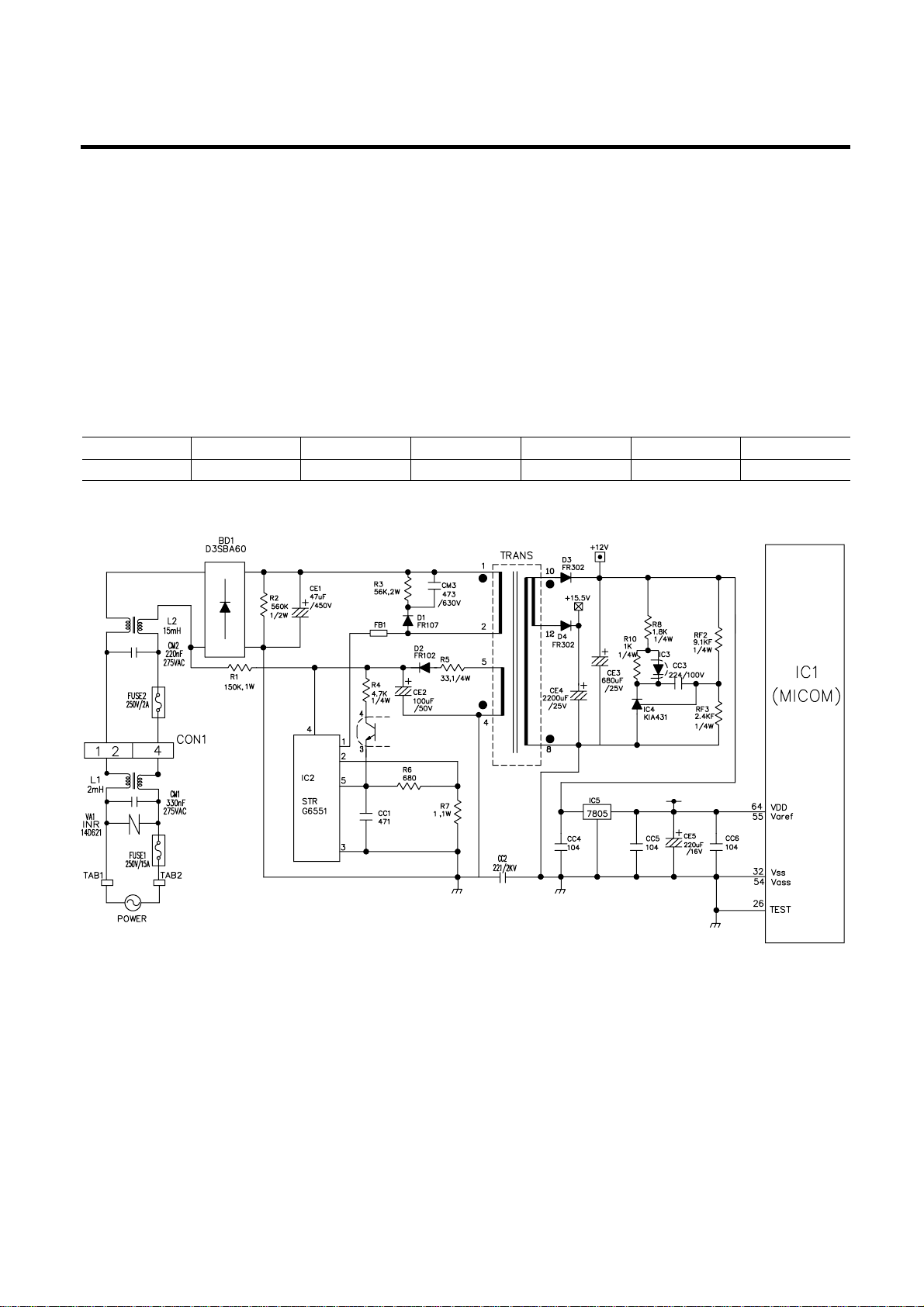
1. Explanation for PWB circuit
1-1. Power circuit
1. GR-P247, L247, C247, B247 / P207, L207, C207, B207
Power circuit consists of SMPS (SWITCHING MODE POWER SUPPLY) power. The SMPS consist of the rectifying part
(BD1, CE1) converting AC voltage to DC voltage, the switching part (IC2) switching the converted DC voltage, transformer
transferring energy of the primary side of the switching terminal to the secondary side and the feedback part (IC3, IC4)
transferring it to the primary side.
Caution : Since high voltage (DC310V) is maintained at the power terminal, please take a measure after more than 3
minutes have passed after removing power cords in the abnormal operation of a circuit.
Voltage of every part is as follows:
EXPLANATION FOR MICOM CIRCUIT
- 30 -
Part VA1 CE1 CE2 CE3 CE4 CE5
Voltage 230 Vac 310 Vdc 16 Vdc 12 Vdc 15.5 Vdc 5 Vdc
Page 31

1-2. Oscillation circuit
Oscillation circuit is a circuit with the purpose of generating basic time for clock occurrence for synchronization and time
calculation in relation with information transmission/reception of inside elements of IC1 (MICOM). The OSC1 must always
use rated parts since if SPEC is changed, time calculated at the IC1 may be changed or no operation is done.
1-3. Reset circuit
The reset circuit is circuit allowing various parts such as RAM inside of MICOM (IC1) to initialize and the whole of function to
start from the initial status, when initial power is input or when power is applied again to MICOM by a spontaneous power
failure. ‘LOW’ voltage is applied to the reset terminal of MICOM in the beginning of power supply for a constant time (10ms).
Reset terminal during general operation is 5V (No MICOM operates in failure of RESET IC).
EXPLANATION FOR MICOM CIRCUIT
- 31 -
<GR-P247, L247, P207, L207> <GR-C247, B247, C207, B207>
<GR-P247, L247, P207, L207> <GR-C247, B247, C207, B207>
Page 32

1-4. Load/dispenser operation, door opening circuit
1. LOAD DRIVING CIRCUIT
✽ In even if opening the door of freezing room or cold storage room during operation of fan motor at the freezing room, this
circuit does not stop and operates at the standard RPM. In addition, if doors of freezing room or cold storage room, the
fan motor normally operates at the RPM previously operated.
✽ (A), (B), (C) and (D) of door switch for the freezing room or freezer are connected to the door open sensing circuit in
parallel toward both ends of switch to determine door open at MICOM.
✽ Since a door switch of the home bar is connected to door switch (C), (D) of the cold storage room, It senses when any
door is opened.
✽ The fan motor is immediately stop if opening doors of the freezer or refrigerator at the TEST mode and it operates
immediately upon their closure.
1) GR-P247, L247, P207, L207
EXPLANATION FOR MICOM CIRCUIT
- 32 -
Measuring part (IC6) IC6-16 IC6-15 IC6-14 IC7-13 IC7-15
Status
ON Within 1 V
OFF 12 V
Type of Load Compressor
Frost Removal
Heater
AC Converting
Relay
Refrigerator
LAMP
Water Tank
Heater
Page 33

2) GR-C247, B247, C207, B207
✽ The fan motor at the freezer does not stop but operates if opening doors of the freezer or refrigerator or the home bar
during operation of the fan motor at the freezer.
✽ (A), (B), (C) and (D) of door switch for the freezer or refrigerator are connected to the door open sensing circuit toward
both ends of switch to determine door open at MICOM.
✽ Since the door switches of the home bar and refrigerator are interconnected, the MICOM can tell when either door is
opened.
EXPLANATION FOR MICOM CIRCUIT
- 33 -
Measuring part (IC7) No.10 No.11 No.12 No.14 No.16
Status
ON Within 1 V
OFF 12 V
Type of Load COMP
Frost Removal
Heater
AC Converting
Relay
R-room LAMP
Home Bar
Heater
Page 34

2. Dispenser operation circuit
1) Check load driving status
2) Lever S/W sensing circuit
EXPLANATION FOR MICOM CIRCUIT
- 34 -
Measuring part
Lever S/W
IC1(Micom) (No. 16)
On(Press)
OFF 5V
Measuring part IC6-13 IC6-12 IC6-11 IC6-10 IC7-12 IC7-10 IC7-16
Status
ON Within 1 V
OFF 12 V
Type of Load
GEARED
MOTOR
SOLENOID
CUBE
WATER VALVE
ICE WATER
SOLENOID
DISPENSER
HOME BAR
HEATER
SOLENOID
PILOT
5 V
0 V
(60 Hz)
Page 35

3. Door opening sensing circuit
1) GR-P247, L247, P207, L207
2) GR-C247, B247, C207, B207, 197
✽ Since door switches (A) and (B) are interconnected, if either fails, the other will not respond properly.
✽ If either switch fails, the light will not come on.
EXPLANATION FOR MICOM CIRCUIT
- 35 -
(Freezing room)
(Cold storage room)
(Cold storage room)
(Freezing room)
(Cold storage room)
(Cold storage room)
Closing 5 V ( A - B , C - D . S/W at both ends are at Off status)
Opening 5 V ( A - B , C - D . S/W at both ends are at On status)
Measuring part
IC1 (MICOM) No. 47, 46 Pin
Door of Freezing/Cold Storage Room
Page 36

1-5. Temperature sensing circuit
1) GR-P247, L247, P207, L207
The above circuits are circuits attached to freezer sensor or refrigerator sensor for adjusting setting temperature at the
freezer and refrigerator, icemaking sensor for sensing water temperature in icemaking, or an evaporator for sensing
temperature of a frost removal sensor necessary for frost removal. Short or open status of every temperature sensor is as
follows:
EXPLANATION FOR MICOM CIRCUIT
- 36 -
SENSOR CHECK POINT
NORMAL(-30 °C ~ 50 °C) IN
SHORT IN OPEN
Freezing sensor POINT A Voltage
Frost removal sensor POINT B Voltage
Cold storage sensor 1 POINT C Voltage
0.5 V~4.5 V 0 V 5 V
Cold storage sensor 2 POINT D Voltage
Icemaking sensor POINT E Voltage
Room temperature sensor POINT F Voltage
A
(Sensor for freezing room)
(Sensor for frost removal)
C
D
B
(Sensor for cold storage room)
(Sensor for cold storage room)
E
F
Page 37

2) GR-C247, B247, C207, B207
The above circuits are circuits attached to freezer sensor or refrigerator sensor for adjusting setting temperature at the
freezer and refrigerator, icemaking sensor for sensing water temperature in icemaking, or an evaporator for sensing
temperature of a frost removal sensor necessary for frost removal. Short or open status of every temperature sensor is as
follows:
EXPLANATION FOR MICOM CIRCUIT
- 37 -
A
C
E
B
D
(Sensor for freezing room)
(Sensor for frost removal)
(Sensor for cold storage room)
(Sensor for cold storage room)
SENSOR CHECK POINT
NORMAL(-30 °C ~ 50 °C) IN
SHORT IN OPEN
Freezing sensor POINT A Voltage
Frost removal sensor POINT B Voltage
Cold storage sensor 1 POINT C Voltage 0.5 V~4.5 V 0 V 5 V
Cold storage sensor 2 POINT D Voltage
Room temperature sensor POINT E Voltage
Page 38

1-6. Switch entry circuit
The following circuits are entry circuits for sensing signal form test switch, electronic single motor damper reed switch for
examining refrigerator.
1) GR-P247, L247, P207, L207 2) GR-C247, B247, C207, B207
1-7. Option designation circuit (model separation function)
1) GR-P247, L247, P207, L207
2) GR-C247, B247, C207, B207
The above circuits are used for designating separation by model as option and notifying MICOM. Designation of option by
model and the application standards are as follows:
u These circuits are accurately pre-adjusted in shipment from factory and so you must not additionally add or remove
option.
EXPLANATION FOR MICOM CIRCUIT
- 38 -
36
R21
4.7K
Separation Connection Status Application Standard
Connection Export model
OP1
OUT Domestic model
Page 39

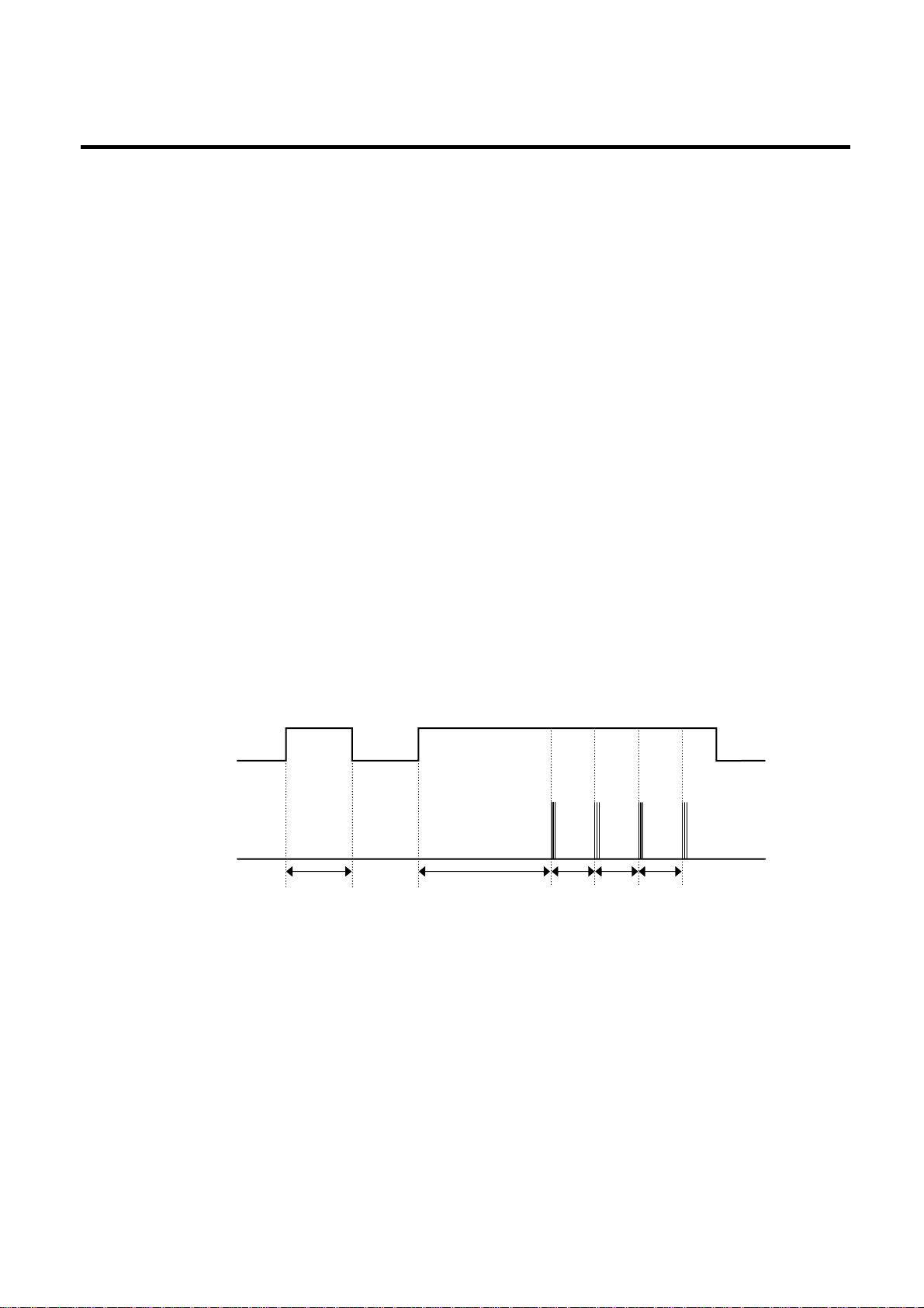
1-8. Stepping motor operation circuit
For motor driving method, rotation magnetism is formed at coils wound on each phase of motor and stator and so motor
becomes to rotate if applying High signal to the IC8 (TA777AF) at the MICOM PIN 33 and outputting High, Low signal by
step numbers fixed through MICOM PIN 34 and 35,.
Explanation) For driving method of the stepping motor, send signals in the cycle of 3.33 mSEC using terminal of MICOM
PIN 33, 34 and 35 as shown in wave form of the following part.
These signals are output to the output terminal (No.10, 11, 14, 15) via the input terminal (No. 3, 6, 8) of the
IC10 (TA7774F) as IC for motor driving. Output signals allow motor coils wound on each phase of stator to
form rotation magnetic field and the motor to rotate. Inputting as below figure to the input terminal (INA, INB)
as IC (TA7774AF) for motor driving allows motor coils wound on each phase of stator to form rotation
magnetic field and the stepping motor damper to rotate
EXPLANATION FOR MICOM CIRCUIT
- 39 -
TA7774F
INA
INB
A
B
A
B
CCW (Reverse rotation) (Positive rotation) CW
Page 40

1-9. Fan motor driving circuit (freezer, mechanical area)
1. The circuit cuts all power to the fan drive IC, resulting in a standby mode.
2. This is a circuit to perform a temporary change of speed for the fan motor and applies DC voltage up to 7.5V ~ 16V to
motor.
3. This circuit performs function not to drive the fan motor further by cutting off power applied to the fan motor in the lock of
fan motor by sensing the operation RPM of the fan motor.
1) GR-P247, L247, P207, L207
EXPLANATION FOR MICOM CIRCUIT
- 40 -
a , d part b part e part c , f part
Motor OFF 5V 2V or less 2V or less 0 V
Motor ON 2 ~ 3V 12 ~ 14V 8 ~ 16V 0 V
b
c
a
e
f
d
Page 41

2) GR-C247, B247, C207, B207
EXPLANATION FOR MICOM CIRCUIT
- 41 -
b
e
c
f
a
d
Speed
Speed
Page 42

1-10. Temperature compensation and temperature compensation circuit
1. Temperature compensation in freezer and refrigerator
1) GR-P247, L247, P207, L207
2) GR-C247, B247, C207, B207
u Temperature compensation table by adjustment value (difference value against current temperature)
Ex) If changing compensation resistance at a cold storage room (RCR1) from 10 kΩ (current resistance) to 18 kΩ
(modified resistance), temperature at the cold storage will increase by +1°C[+1.8°F].
EXPLANATION FOR MICOM CIRCUIT
- 42 -
Temperature compensation at refrigerator
Temperature compensation at freezer
Temperature compensation at refrigerator
Temperature compensation at freezer
Freezer Refrigerator
Resistance value Temperature Resistance value Temperature Remarks
(RCF1) compensation (RCR1) compensation
180 kΩ +5 °C [+9°F] 180 kΩ +2.5 °C [+4.5°F] Warmer
56 kΩ +4 °C [+7.2°F] 56 kΩ +2.0 °C [+3.6°F]
33 kΩ +3 °C [+5.4°F] 33 kΩ +1.5 °C [+2.7°F]
18 kΩ +2 °C [+3.6°F] 18 kΩ +1.0 °C [+1.8°F]
12 kΩ +1 °C [+1.8°F] 12 kΩ +0.5 °C [+0.9°F]
10 kΩ 0 °C [0°F] 10 kΩ 0 °C [0°F]
Reference temperature
8.2 kΩ -1 °C [-1.8°F] 8.2 kΩ -0.5 °C [-0.9°F]
5.6 kΩ -2 °C [-3.6°F] 5.6 kΩ -1.0 °C [-1.8°F]
3.3 kΩ -3 °C [-5.4°F] 3.3 kΩ -1.5 °C [-2.7°F]
2 kΩ -4 °C [-7.2°F] 2 kΩ -2.0 °C [-3.6°F]
470 Ω -5 °C [-9°F] 470 Ω -2.5 °C [-4.5°F] Cooler
Page 43

u Temperature compensation table at the refrigerator is as follows:
u Temperature compensation at the freezer is also performed in the same manner as refrigerator. Temperature
compensation value is equivalent to two times the refrigerator.
u This circuit is a circuit to enter the necessary level of temperature compensation for adjusting different temperature every
model at the refrigerator into MICOM.
EXPLANATION FOR MICOM CIRCUIT
- 43 -
470 Ω 2 kΩ 3.3 kΩ 5.6 kΩ 8.2 kΩ 10 kΩ 12 kΩ 18 kΩ 33 kΩ 56 kΩ 180 kΩ
No 0.5 °C1 °C 1.5 °C2 °C 2.5 °C3 °C 3.5 °C4 °C 4.5 °C5 °C
470Ω [0.9 °F] [1.8 °F] [2.7 °F] [3.6 °F] [4.5 °F] [5.4 °F] [6.3 °F] [7.2 °F] [8.1 °F] [9 °F]
change
Up Up Up Up Up Up Up Up Up Up
0.5 °C No 0.5 °C1 °C 1.5 °C2 °C 2.5 °C3 °C 3.5 °C4 °C 4.5 °C
2 kΩ [0.9 °F] [0.9 °F] [1.8 °F] [2.7 °F] [3.6 °F] [4.5 °F] [5.4 °F] [6.3 °F] [7.2 °F] [8.1 °F]
Down change
Up Up Up Up Up Up Up Up Up
1 °C 0.5 °C No 0.5 °C1 °C 1.5 °C2 °C 2.5 °C3 °C 3.5 °C4 °C
3.3 kΩ [1.8 °F] [0.9 °F] [0.9 °F] [1.8 °F] [2.7 °F] [3.6 °F] [4.5 °F] [5.4 °F] [6.3 °F] [7.2 °F]
Down
Down
change
Up Up Up Up Up Up Up Up
1.5 °C1 °C 0.5 °C No 0.5 °C1 °C 1.5 °C2 °C 2.5 °C3 °C 3.5 °C
5.6 kΩ [2.7 °F] [1.8 °F] [0.9 °F] [0.9 °F] [1.8 °F] [2.7 °F] [3.6 °F] [4.5 °F] [5.4 °F] [6.3 °F]
Down Down Down
change
Up Up Up Up Up Up Up
2 °C 1.5 °C1 °C 0.5 ° No 0.5 °C1 °C 1.5 °C2 °C 2.5 °C3 °C
8.2 kΩ [3.6 °F] [2.7 °F] [1.8 °F] [0.9 °F] [0.9 °F] [1.8 °F] [2.7 °F] [3.6 °F] [4.5 °F] [5.4 °F]
Refrigerator
Down Down
Drop
Down
change
Up Up Up Up Up Up
(RCR1) 2.5 °C2 °C 1.5 °C1 °C 0.5 °C No 0.5 °C1 °C 1.5 °C2 °C 2.5 °C
10 kΩ [4.5 °F] [3.6 °F] [2.7 °F] [1.8 °F] [0.9 °F] [0.9 °F] [1.8 °F] [2.7 °F] [3.6 °F] [4.5 °F]
Down Down Down Down Down
change
Up Up Up Up Up
3 °C 2.5 °C2 °C 1.5 °C1 °C 0.5 °C No 0.5 °C1 °C 1.5 °C2 °C
12 kΩ [5.4 °F] [4.5 °F] [3.6 °F] [2.7 °F] [1.8 °F] [0.9 °F] [0.9 °F] [1.8 °F] [2.7 °F] [3.6 °F]
Down Down Down Down Down Down
change
Up Up Up Up
3.5 °C3 °C 2.5 °C2 °C 1.5 °C1 °C 0.5 °C No 0.5 °C1 °C 1.5 °C
18 kΩ [6.3 °F] [5.4 °F] [4.5 °F] [3.6 °F] [2.7 °F] [1.8 °F] [0.9 °F] [0.9 °F] [1.8 °F] [2.7 °F]
Down Down Down Down Down Down Down
change
Up Up Up
4 °C 3.5 °C3 °C 2.5 °C2 °C 1.5 °C1 °C 0.5 °C No 0.5 °C1 °C
33 kΩ [7.2 °F] [6.3 °F] [5.4 °F] [4.5 °F] [3.6 °F] [2.7 °F] [1.8 °F] [0.9 °F] [0.9 °F] [1.8 °F]
Down Down Down Down Down Down Down Down
change
Up Up
4.5 °C4 °C 3.5 °C3 °C 2.5 °C2 °C 1.5 °C1 °C 0.5 °C No 0.5 °C
56 kΩ [8.1 °F] [7.2 °F] [6.3 °F] [5.4 °F] [4.5 °F] [3.6 °F] [2.7 °F] [1.8 °F] [0.9 °F] [0.9 °F]
Down Down Down Down Down Down Down Down Down
change
Up
5 °C 4.5 °C4 °C 3.5 °C3 °C 2.5 °C2 °C 1.5 °C1 °C 0.5 °CNo
180 kΩ [9 °F] [8.1 °F] [7.2 °F] [6.3 °F] [5.4 °F] [4.5 °F] [3.6 °F] [2.7 °F] [1.8 °F] [0.9 °F]
Down Down Down Down Down Down Down Down Down Down
change
Modification
resistance
Current
resistance
Page 44

2. Compensation circuit for too warm, too cold at freezer.
1) GR-P247, L247, P207, L207 2) GR-C247, B247, C207, B207
u The above option circuit is a circuit to compensate for temperature at the refrigerator by simply cutting in service.
EXPLANATION FOR MICOM CIRCUIT
- 44 -
Compensation Compensation
for weak-cold for over-cold
Temperature compensation value
Remarks
JCR3 JCR4 JCR1 JCR2
at cold storage room
0 °C (In shipment from factory)
CUT -1 °C [-1.8 °F]
CUT -1 °C [-1.8 °F]
CUT +1 °C [+1.8 °F]
CUT +1 °C [+1.8 °F]
CUT CUT -2 °C [-3.6 °F]
CUT CUT +2 °C [+3.6 °F]
CUT CUT 0 °C [0 °F]
CUT CUT 0 °C [0 °F]
CUT CUT 0 °C [0 °F]
CUT CUT 0 °C [0 °F]
CUT CUT CUT -1 °C [-1.8 °F]
CUT CUT CUT +1 °C [+1.8 °F]
CUT CUT CUT CUT 0 °C [0 °F]
Temperature compensation in CUT
JCR1 +1 °C [+1.8 °F]
+2 °C [+3.6 °F]
JCR2 +1 °C [+1.8 °F]
JCR3 -1 °C [-1.8 °F]
-2 °C [-3.6 °F]
JCR4 -1 °C [-1.8 °F]
Page 45

1-11. Communication circuit and connection L/Wire between main PCB and display PCB
The following circuit is a communication circuit used for exchanging the necessary information between main MICOM of
main PCB and LCD dedicated MICOM for LCD control of display PCB.
Transmission/receipt L/Wire together with the necessary display PCB for driving the display PCB is required.
Poor communication occurs if a continuous information exchange fail to continue for more than 2 minutes between main
MICOM of main PCB and LCD dedicated MICOM for LCD control of display PCB.
1) GR-P247, L247, P207, L207
EXPLANATION FOR MICOM CIRCUIT
- 45 -
GND
12Vdc
Transmission
Transmission
Reception
Reception
CRUSHED CUBED
WATER
FRZ TEMP
REF TEMP
DISPENSER
LOCK
SUPER FRZ
OFF
MAXMIN
MAXMIN
TEMP
TEMP
ROOM
TEMP
°F
°F
°F
PCB ASSEMBL Y DISPLA Y
Main MICOM LCD dedicated MICOM
DC 12V
GND
Transmission (error status)
Reception (notch status)
Main PCB L/Wire FD/H(4-wires) Display PCB
Page 46

2) GR-C247, B247, C207, B207
2. Sensor resistance characteristics table
u Resistance value allowance of sensor is ±5%.
u In measuring resistance value allowance of sensor, perform measuring after leaving the sensor for more than 3 minutes
at the measuring temperature (delay is required due to sense speed relation relationship).
u Since an analog tester has a large measuring temperature, measuring with a digital tester is required as possible as.
u Resistance of the cold storage sensor 1 and 2 shall be measured with a digital tester after separating CON8 of the PWB
ASSEMBLY and the MAIN part.
u Resistance of the freezing sensor shall be measured with a digital tester after separating CON7 of the PWB ASSEMBLY
and the MAIN part.
EXPLANATION FOR MICOM CIRCUIT
- 46 -
Measuring T emperature (°C) Freezing Sensor
Cold storage sensor 1, 2.
Frost removal sensor, Outside sensor
-20 °C 22.3 kΩ 77 kΩ
-15 °C 16.9 kΩ 60 kΩ
-15 °C 13.0 kΩ 47.3 kΩ
-5 °C 10.1 kΩ 38.4 kΩ
0 °C 7.8 kΩ 30 kΩ
+5 °C 6.2 kΩ 24.1 kΩ
+10 °C 4.9 kΩ 19.5 kΩ
+15 °C 3.9 kΩ 15.9 kΩ
+20 °C 3.1 kΩ 13 kΩ
+25 °C 2.5 kΩ 11 kΩ
+30 °C 2.0 kΩ 8.9 kΩ
+40 °C 1.4 kΩ 6.2 kΩ
+50 °C 0.8 kΩ 4.3 kΩ
12Vdc
Reception
Transmission
FRZ TEMP
REF TEMP
TEMP
TEMP
Transmission
GND
Reception
PCB ASSEMBL Y DISPLA Y
°F
°F
MAXMIN
ROOM
°F
TEMP
MAXMIN
OFF
LOCK
SUPER FRZ
Page 47

3. PWB parts diagram and list
3-1. PWB Assembly, main part diagram
1. GR-P247, L247, P207, L207
EXPLANATION FOR MICOM CIRCUIT
- 47 -
Page 48

2. GR-C247, B247, C207, B207
EXPLANATION FOR MICOM CIRCUIT
- 48 -
Page 49

3-2. Parts list
1. GR-P247, L247, P207, L207
EXPLANATION FOR MICOM CIRCUIT
- 49 -
Page 50

EXPLANATION FOR MICOM CIRCUIT
- 50 -
WATER
SUPPLY
S/W
Page 51

2. GR-C247, B247, C207, B207
EXPLANATION FOR MICOM CIRCUIT
- 51 -
Page 52

EXPLANATION FOR MICOM CIRCUIT
- 52 -
WATER
SUPPLY
S/W
Page 53

3-3. DISPLAY ASSEMBLY part diagram
1. GR-P247, L247, P207, L207
EXPLANATION FOR MICOM CIRCUIT
- 53 -
Page 54

2. GR-C247, B247, C207, B207
EXPLANATION FOR MICOM CIRCUIT
- 54 -
DOUBLE SIDE TAPE
SPREAD SHEET
Page 55

3-4. DISPLAY circuit diagram
1. GR-P247, L247, P207, L207
EXPLANATION FOR MICOM CIRCUIT
- 55 -
Parts without ( ) mark means SMD parts.
Page 56

2. GR-C247, B247, C207, B207
EXPLANATION FOR MICOM CIRCUIT
- 56 -
Reception
Transmission
Parts without ( ) mark means SMD parts.
Page 57

4. PWB circuit diagram - PWB circuit diagram may vary a little bit depending on actual condition.
1. GR-P247, L247, P207, L207
EXPLANATION FOR MICOM CIRCUIT
- 57 -
PWB ASSEMBL Y , MAIN
Page 58

EXPLANATION FOR MICOM CIRCUIT
- 58 -
PCB ASSEMBLY , DISPLA Y
Page 59

2. GR-C247, B247, C207, B207
EXPLANATION FOR MICOM CIRCUIT
- 59 -
PWB ASSEMBL Y , MAIN
Page 60

EXPLANATION FOR MICOM CIRCUIT
- 60 -
PCB ASSEMBLY, DISPLAY
Page 61

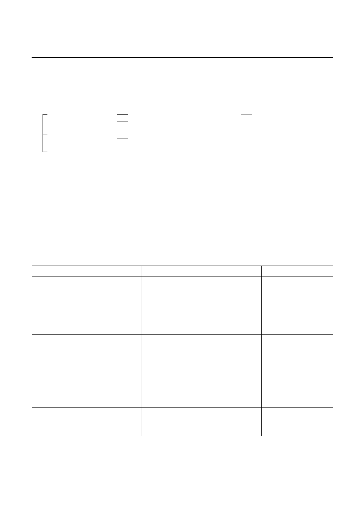
1. Working Principles
1-1. Icemaker Working Principles
1-2. Dispenser Working Principles
1. This function is available in Model GR-P247, GR-P207 and GR-L247, GR-L207 where water and ice are available without
opening freezer compartment door.
2. Crushed Ice is automatically selected when power is initially applied or reapplied after power cut.
3. When dispenser selection switch is continuously pressed, light is on in the following sequence:
Water → Cube Ice → Crushed Ice.
4. Lamp is on when dispenser bushing button is pressed and vice versa.
5. When dispenser crushed ice bushing button is pressed, dispenser solenoid and geared motor work so that crushed ice
can be dispensed if there is ice in the ice bin.
6. When dispenser cube ice bushing button is pressed, dispenser solenoid, cube ice solenoid and geared motor work so
that cube ice can be dispensed if there is ice in the ice bin.
7. When dispenser water bushing button is pressed, water valve opens and water is supplied if water valve is normally
installed on the right side of the compressor area.
8. Ice and water are not available when freezer door is open.
ICEMAKER AND DISPENSER OPERA TION PRINCIPLE AND REPAIR METHOD
- 61 -
• Level Icemaker Cube Mould for Initial Control
after power is input.
Power Input
Initial Control
Ice Making Control
Ice Ejection Control
Water Supply Control
Test Control
• Wait until the water in the cube mould is frozen
after icemaker starts operation.
• Check ice bin is full of ice by rotating ice ejection
motor in normal and reverse direction and eject ice into
the ice bin if ice bin is not full.
•
This is for refrigerator assembly line and service. When icemaking test switch is pressed,
it operates in the following steps: initial ice ejection water supply control steps.
• Conduct Icemaking Control after supplying water into the Icemaker
cube mould by operating water valve.
Page 62

2. Function of Icemaker
2-1. Initial Control Function
1. When power is initially applied or reapplied after power cut, it detects level of icemaker cube mould after completion of
MICOM initialization. The detecting lever moves up and down.
2. The level of icemaker cube mould is judged by output signal, high and low signal, of Hall IC. Make the cube mould to be
horizontal by rotating ice ejection motor in normal or reverse direction so that High/Low signal can be applied to MICOM
Pin No. 42.
3. If there is no change in signals one minute after the geared motor starts to operate, it stops icemaker operation and check
the signal every hour. It resets initialization of icemaker when it becomes normal.
4. It judges that the initial control is completed when it judges the icemaker cube mould is horizontal.
5. Ice ejection conducts for 1 cycle irrespect of ice in the ice bin when power is initially applied.
2-2. Water Supply Control Function
1. This is to supply water into the icemaker cube mould by operating water valve in the machine room when ice ejection
control is completed and icemaker mould is even.
2. The quantity of water supplied is determined by DIP switch and time.
<Water Supply Quantity Table>
3. If water supply quantity setting is changed while power is on, water supplies for the amended time. If DIP switch is
changed during water supply, water shall be supplied for the previous setting time. But it will supply for the amended time
from the next supply.
4. When water supply signal is applied to water and ice valves at the same time during water supply, water shall be supplied
to water valve. If water supply signal is applied to ice valve during water supply, water shall be supplied to both water and
ice valves.
2-3. Icemaking Control Function
1. Icemaking control is carried out from the completion of water supply to the completion of icemaking in the cube mould.
Icemaking sensor detects the temperature of cube mould and completes icemaking. (icemaking sensor is fixed below
icemaker cube mould)
2. Icemaking control starts after completion of water supply control or initial control.
3. It is judged that icemaking is completed when icemaking sensor temperature reaches at -8°C[18°F] after 100 minutes
when water is supplied to icemaker cube mould.
4. It is judged that icemaking is completed when icemaker sensor temperature reaches below -12°C[10°F] after 20 minutes
in condition 3.
ICEMAKER AND DISPENSER OPERA TION PRINCIPLE AND REPAIR METHOD
- 62 -
DIP SWITCH SETTING
No
SWITCH 1 SWITCH 2 SWITCH 3
WATER SUPPLY TIME REMARKS
1 OFF OFF OFF 6.5 Sec.
2 ON OFF OFF 5.5 Sec.
3 OFF ON OFF 6 Sec.
4 ON ON OFF 7 Sec.
5 OFF OFF ON 7.5 Sec.
6 ON OFF ON 8 Sec.
7 OFF ON ON 9 Sec.
8 ON ON ON 10 Sec.
* The quantity of water supplied
depends on DIP switch setting
conditions and water pressure as it is
a direct tap water connection type.
(the water supplied is generally 80 cc
to 120 cc)
* DIP switch is on the main PWB.
Page 63

2-4. Ice Ejection Control Function
1. This is to eject ice from icemaker cube mould after icemaking is completed.
2. If Hall IC signal is on within 3.6 seconds after ice ejection motor rotates in normal direction, it does not proceed ice
ejection but waits. If the ice bin is full, ice ejection motor rotates in normal direction in every hour to check the condition of
ice bin. If the ice bin is not full, the water supply control starts after completion of ice ejection control. If the ice bin is full,
ice ejection motor rotates in reverse direction and stops under icemaking or waiting conditions.
3. If ice bin is not full, ice ejection starts. The cube mould tilts to the maximum and ice is separated from the mould and ice
checking lever raises.
4. Ice ejection motor stops for 1 second if Hall IC signal changes from OFF (low) to ON (high) after 3.6 seconds when ice
ejection motor rotates in normal direction. If there is no change in Hall IC signals within 1 minute after ice ejection motor
operates, ice ejection motor stops as ice ejection motor or hall IC is out of order.
5. If ice ejection motor or Hall IC is abnormal, ice ejection motor rotates in normal direction to exercise initial operation. It
resets the icemaker if ice ejection motor or Hall IC is normal.
6. The mould stops for 1 second at maximum tilted conditions.
7. The mould returns to horizontal conditions as ice ejection motor rotates in reverse direction.
8. When the mould becomes horizontal, the cycle starts to repeat:
Water Supply → Icemaking → Ice Ejection → Mould Returns to Horizontal
ICEMAKER AND DISPENSER OPERA TION PRINCIPLE AND REPAIR METHOD
- 63 -
Bin is
not full
HALL IC
OUTPUT
SIGNALS
Bin is
full
HALL IC
OUTPUT
SIGNALS
ICE CHECKING
AXIS
ICE CHECKING LEVEL 30°
Maximum tilting
point
Icemaking
(Original point)
Lock
2±1 sec
9±3 sec
8±3 sec
Ice Checking Ice Ejection
Lock
Horizontal
Conditions
Level Retrun
Conditions
<Timing Chart During Ice Ejection>
Page 64

2-5 Test Function
1. It is to force the operation during operation test, service, and cleaning. The test switch is mounted under the automatic
Icemaker. The test function starts when the test switch is pressed for more than 0.5 second.
2. Test button does not work during ice ejection and water supply. It works when it is in the horizontal conditions. If mould is
full of ice during test function operation, ice ejection control and water supply control do not work.
3. When test switch is pressed for more than 0.5 second in the horizontal conditions, ice ejection starts irrespect of the
mould conditions. Water shall be splashed if test switch is pressed before the water in the mould freezes. Water shall be
supplied while the mould returns to the horizontal conditions after ice ejection. Therefore the problems of ice ejection,
returning to the horizontal conditions, and water supply can be checked by test switch. When test function performs
normally, the buzzer sounds and water supply shall carry out. Check it for repair if buzzer does not sound.
4. When water supply is completed, the cycle operates normally as follows: Icemaking → Ice ejection → Returning to
horizontal conditions → Water supply
5. Remove ice from the icemaker cube mould and press test switch when icemaker cube mould is full of ice as ice ejection
and water supply control do not work when cube mould is full of ice.
2-6. Other functions relating to freezer compartment door opening
1. When freezer door is open, ice dispenser stops in order to reduce noise and ice drop.
2. When freezer door is open during ice ejection and cube mould returning to horizontal condition, ice ejection and cube
mould level return proceed.
3. When freezer door is open, geared motor and cube ice solenoid immediately stop and duct door solenoid stops after 5
seconds.
4. Water dispenser stops in order to protect water drop when freezer door is open.
5. Test function operates normally irrespect of refrigearator compartment door opening.
ICEMAKER AND DISPENSER OPERA TION PRINCIPLE AND REPAIR METHOD
- 64 -
Page 65

3. Icemaker Troubleshooting
* Troubleshooting: it is possible to confirm by pressing freezer and refrigerator temperature control buttons for more
than 1 second. (Icemaker is normal if all leds are on): refer to trouble diagnposis function in MICOM
function 2-8 (page 18)
ICEMAKER AND DISPENSER OPERA TION PRINCIPLE AND REPAIR METHOD
- 65 -
No
Yes
Yes
Yes
No
No
No
No
Yes
Yes
Is DC Power (5V and 12V)
output normal?
Failed DC Power
• Check DC power (5V, 12V).
Change main PWB
Is cube ice LCD off during
troubleshooting check?
Failed Icemaking sensor
• Check the resistance of
both ends (1,2) of icemaking
sensor of CON9.
• Defects between icemaking
sensor and board
(Pin No. 60 of IC1)
Replace Icemaking
Sensor
Is Crushed Ice LCD off during
troubleshooting check?
Failed Icemaker Unit
• Is the resistance of both ends
9,10 of ice ejection motor of
CON9 between 18 and 22Ω?
• Is ice ejection motor drive circuit
(IC11 and peripheral circuits)
normal?
• Defects between Hall IC and
Board (Pin No. 42 of IC1).
• Confirm ice ejection and level
return when pressing
test switch.
Replace Icemaker Unit
Replace Main PWB
Are ice
ejection and level return
normal when test switch is
pressed for more than 0.5 second?
Does the bell
sound once?
Failed Icemaker unit test switch
• Are both ends 5,6 of CON9
test switch open?
• Defects between test switch
and board (Pin No. 38 of IC1).
• Are both ends (3,4) of CON9
Icemaker stop switch short?
Replace Icemaker Unit
Replace water
supply valve
• Is power applied to water
supply valve?
• Does the water supply
valve work normally?
• Is the water supply line
normally connected?
Poor water supply
Is water suppy normal
after Ice ejection and level return
by ice ejection motor?
Normal
Page 66

4. Icemaker circuit part
The above icemaker circuit is applied to the GR-P247/207, GR-L247/207 and consists of the icemaker unit part installed at
the freezing room and the icemaker driving part of the main PWB.
Water supply to the icemaker container is done by opening the valve for the established water supply time by operating the
container via a solenoid relay for the ice valve of the solenoid valve placed at the M/C room. If the water supply time is
elapsed, water supply is automatically stop. This circuit is a circuit for implementing function such as ice removal, ice-full
detection, horizontal balancing and sense of icemaking temperature for the icemaker container. Since icemaking
temperature sense is same as in the temperature sense circuit part of the main PWB, refer to it.
Test switch input detection of the icemaker is same as in the door switch input detection circuit of the main PWB.
1. This function is used in operation test, service execution and cleaning etc and performed if pressing the test switch
installed at the automatic icemaker itself for more than 0.5 second.
2. The test switch operates in the horizontal status and test function is not input in the water supply operation. Ice removal
control and water supply control is not performed if full-ice is arrived during the operation of test function.
3. If pressing the test switch for 0.5 second or more in the horizontal status, ice removal operation is immediately performed
irrespective of the generation conditions of ice at the icemaking tray. Therefore, care is required since water may overflow
if operating test function in the water state that icemaking is not done. A cycle of water supply is performed in the
horizontal balancing operation after ice removal operation. Therefore, you can check any problem of ice removal
operation, horizontal operation and water supply. In this case, if test function is normally performed, Ding~ buzzer sound
rings and water supply control is performed. Thus, no ringing of Ding~ buzzer sound means failure and repair check must
be performed.
4. If water supply is completed, operation in the normal cycle of icemaking → ice removal → returning to horizontal
status → water supply.
ICEMAKER AND DISPENSER OPERA TION PRINCIPLE AND REPAIR METHOD
- 66 -
Page 67

CIRCUIT
- 67 -
Page 68

CIRCUIT
- 68 -
Page 69

1. TROUBLE SHOOTING
TROUBLE DIAGNOSIS
- 69 -
CLAIMS. CAUSES AND CHECK POINTS. HOW TO CHECK
1. Faulty start
1) No power on outlet.
2) No power on cord.
3) Shorted start circuit.
4) During defrost.
* Measuring instrument :
Multi tester
■Check the voltage.
If the voltage is within ±85%
of the rated voltage, it is OK.
■ Check the terminal
movement.
■
Check both terminals of
power cord.
Power conducts : OK.
No power conducts : NG
■ Check both terminals of OLP.
If power conducts : OK.
If not : NG.
■ Check the resistance of both
terminals.
At normal temperature 6 :
OK.
If disconnected : ∞.
Bad connection between adapter and outlet. (faulty adapter)
The Inner diameter of adapter.
The distance between holes.
The distance between terminals.
The thickness of terminal.
Bad connection between plug and adapter (faulty plug).
The distance between pins.
Pin outer diameter.
No power on
power cord.
O.L.P is off.
No electric power on compressor. - Faulty compressor .
Faulty PTC.
Disconnected copper wire.
Internal electrical short.
Faulty terminal contact.
Disconnected.
Capacity of O.L.P is small.
Characteristics of O.L.P is bad.
Bad connection.
Power is
disconnected.
Inner Ni-Cr wire blows out.
Bad internal connection.
Faulty terminal caulking (Cu wire is cut).
Bad soldering.
Weak connection.
Short inserted cord length.
Worn out tool blade.
Loose contact.
- Large distance between
male terminal.
- Thin female terminal.
T erminal disconnected.
Bad sleeve assembly .
Power cord is disconnected.
Faulty soldering.
Start automatic defrost.
Cycle was set at defrost when the refrigerator
was produced.
Power does not conduct. - Damage.
Bad characteristics. - Initial resistance is big.
Bad connection with
compressor.
Bad terminal connection.
T oo loose.
Assembly is not possible.
Page 70

TROUBLE DIAGNOSIS
- 70 -
CLAIMS. CAUSES AND CHECK POINTS. HOW TO CHECK
2. No cooling.
2) Refrigeration system is clogged.
■Check the clogged
evaporator by heating (as
soon as the cracking sound
begins, the evaporator start
freezing)
■ The evaporator does not cool
from the beginnig (no evidece
of moisture attached).
The evaporator is the same
as before even heat is
applied.
Moisture
clogged.
No electric
power on
thermostat.
Weld joint
clogged.
Drier cloggeing.
Foreign material clogging.
Residual moisture
in the evaporator.
Residual moisture.
Insufficient drier
capacity.
Residual moisture
in pipes.
Moisture penetration - Leave it in the air. - Moisture penetration.
into the refrigeration oil.
Caps are missed.
Air blowing.
During transportation.
During work.
Not performed.
Performed.
T oo short time.
Low air pressure.
Less dry air.
Air Blowing.
Leave it in the air.
Caps are missed.
Short pipe insert.
Pipe gaps.
T oo much solder .
T oo large.
Damaged pipes.
Not dried in the compressor.
Elapsed more than 6 months after drying
Caps are missed.
No pressure when it is open.
During rest time.
After work.
Compressor cap is disconnected.
Foreign materials are in the pipe.
Not performed.
T oo short.
Impossible moisture
confirmation.
Low air pressure.
Dry drier - Drier temperature.
Leave it in the air.
The capillary tube inserted depth. - T oo much.
Capillary tube melts. - Over heat.
Clogged with foreign materials.
Reduced cross section by cutting. - Squeezed.
Desiccant powder.
Weld oxides.
Drier angle.
Check on package
condition.
Good storage after
finishing.
Page 71

TROUBLE DIAGNOSIS
- 71 -
CLAIMS. CAUSES AND CHECK POINTS. HOW TO CHECK
3. Refrigeration
is weak.
Plate
heater
Cord
heater
1) Refrigerant Partly leaked.
2) Poor defrosting capacity.
Drain path (pipe) clogged.
Defrost heater does not
generate heat.
Weld joint leak.
Parts leak.
Inject P/U into drain hose.
Foreign materials
penetration.
Cap drain is not disconnected.
Inject through the
hole.
Seal with drain.
P/U lump input.
Screw input.
Other foreign materials
input.
Parts
disconnected.
Wire is cut.
- Heating wire.
- Contact point
between heating
and electric wire.
Dent by fin evaporator.
Poor terminal contacts.
Wire is cut.
- Lead wire.
- Heating wire.
- Contact point
between heating and
electric wire.
Heating wire is corroded
- Water penetration.
Bad terminal connection.
■Check visually.
■Check terminal
Conduction: OK.
No conduction: NG.
If wire is not cut, refer to
resistance.
P=Power
V=Voltage
R=Resistance
V
2
P= —
R
V
2
R= —
P
Page 72

- 72 -
TROUBLE DIAGNOSIS
CLAIMS. CAUSES AND CHECK POINTS. HOW TO CHECK
3. Refrigeration
is weak.
3) Cooling air leak.
4) No cooling air circulation.
Residual
frost.
No automatic defrosting.
Defrost does not return.
Bad gasket adhestion
Door sag.
Faulty fan motor.
Weak heat from heater.
Bad heater assembly .
T oo short defrosting time. Defrost Sensor.
- Faulty characteristics.
Seat-D(missing, location. thickness).
Structural fault. Gasket gap.
Air inflow through the fan motor.
Bad insulation of case door.
Sheath Heater - rated.
Heater plate - rated.
Heater cord-L - rated.
Heater plate
Heater cord-L
Gap.
Bad attachment.
Contraction.
Bad adhesion.
Weak binding force at hinge.
Fan motor.
Door switch.
Self locked.
Wire is cut.
Bad terminal contact.
Contact distance.
Button pressure.
Melted contact.
Contact.
Poor door
attachment.
Door liner
(dimension).
Contraction inner
liner.
Misalignment.
Bad terminal
connection.
P/U liquid leak.
Faults.
Refrigerator and freezer switch reversed.
Button is not pressed.
No contact to drain.
Loosened stopper cord.
Not contact to the
evaporator pipe.
Location of assembly
(top and middle).
■Check the fan motor
conduction: OK.
No conduction: NG.
Page 73

TROUBLE DIAGNOSIS
- 73 -
CLAIMS. CAUSES AND CHECK POINTS. HOW TO CHECK
3. Refrigeration
is weak.
4) No cooling air circulation.
5) Compressor capacity.
6) Refrigerant
too much or too little.
7) Continuous operation
- No contact of temperature controller. - Foreign materials.
8) Damper opens continuously.
Foreign materials
jammed.
Failed sensor. - Position of sensor.
Characteristics
of damper.
9) Food storing place. - Near the outlet of cooling air.
Faulty fan motor.
Small cooling air
discharge.
Fan is
constrained.
Insufficient
motor RPM
Faulty fan.
Shorud. Bent.
Ice and foreign materials on rotating parts.
Fan shroud contact. - Clearance.
Damping evaporator contact.
Accumulated residual frost.
Fan misuse.
Bad shape.
Loose connection. - Not tightly connected.
Insert depth.
Rating misuse.
Small capacity.
Low valtage.
Malfunction of charging cylinder.
Wrong setting of refrigerant.
Insufficient compressor. - Faulty compressor.
Fan overload. - Fan misuse.
Bad low termperature RPM characteristics.
Rated power misuse.
Low voltage.
P/U liquid dump.
EPS water sediment.
Screw.
Bad characteristics of its own temperatue.
Parts misuse.
Charge of temperature - Impact.
characteristics.
■Check visually after
disassembly.
■Check visually after
disassembly.
Page 74

TROUBLE DIAGNOSIS
- 74 -
CLAIMS. CAUSES AND CHECK POINTS. HOW TO CHECK
4. Warm
refrigerator
compartment
temperature.
5. No automatic
operation.
(faulty
contacts.)
6. Condensation
and ice
formation.
1) Colgged cooling path.
2) Food storate.
1) Faulty temperature sensor in freezer or refrigerator compartment.
2) Refrigeration load is too much.
3) Poor insulation.
4) Bad radiation.
5) Refrigerant leak.
6) Inadequate of refrigerant.
7) Weak compressor discharging power.
8) Fan does not work.
9) Button is positioned at strong.
1) Ice in freeezer compartment.
2) Condensation in the refrigerator compartment.
3) Condensation on liner foam.
P/U liquid leak.
Foreign materials. –– P/U dump liquid.
Faulty contact.
Faulty temperature characteristics.
External air inflow. –– Bushing installed incorrectly .
Door opens
but not closes.
Gap around gasket. –– Contraction, distortion, loose, door twisted, corner not
fully inserted.
Food vapor. –– Storing hot food. –– Unsealed food.
Door opens
but not closes.
Gasket gap.
Cool air leak
and transmitted.
High ambient temperature.
Space is secluded.
Different rating.
Small capacity.
Store hot food.
Store too much at once.
Door open.
Packages block air flow.
Food.
Frequent opening and closing.
Cool air leak.
Poor door close. – Partly opens.
T oo much food.
Hot food.
Weak door closing power .
Stopper malfunction.
Door sag.
Food hinders door closing.
Insufficient closing.
Door sag.
Food hinders door closing.
T oop table part.
Out plate R/L part.
Not fully filled.
Flange gap. –– Not sealed.
Gasket gap.
■Inspect parts measurements
and check visually.
Page 75

TROUBLE DIAGNOSIS
- 75 -
CLAIMS. CAUSES AND CHECK POINTS. HOW TO CHECK
6. Condensation
and ice
formation.
7. Sounds
4) Condensation on door.
Condensation on the duct door. - Duct door heater is cut.
Condensation on the
dispense recess.
Condensation on the Not fully filled. Surface.
door surface. Cormer.
P/U liquid contraction.
Condensation
on the gasket
surface.
5) Water on the floor.
Condensation in the refrigerator compartment.
Defrosted water overflows. Clogged discharging hose.
Discharging hose Evaporation tray located at wrong place.
location.
Tray drip. Damaged.
Breaks, holes.
Small Capacity.
Position of drain.
1) Compressor compartment operating sounds.
Compressor sound Sound from machine itself.
inserted. Sound from vibration.
Restrainer.
Bushing Too hard.
seat. Distorted.
Aged.
Burnt.
Stopper. Bad Stopper Not fit
assembly. (inner
diameter
of stopper).
Tilted.
Not
Compressor base not connected.
Bad welding compressor stand fallen.
Foreign materials in the compressor
compartment.
OLP
sound.
Chattering
sound.
Insulation paper vibration.
Capacitor noise.
Pipe contacts each other. – Narrow interval.
Pipe sound. No vibration damper.
Damping Bushing-Q.
Damping Bushing-S.
Capillary tube unattached.
Recess Heater is cut.
Duct door is open. / Foreign material clogging.
Bad wing adhesion. Wing sag(lower part).
Door liner shape mismatch.
Corner. T oo much notch.
Broken.
Home Bar heater is cut.
Liquid shortage.
Liquid leak.
Page 76

TROUBLE DIAGNOSIS
- 76 -
CLAIMS. CAUSES AND CHECK POINTS. HOW TO CHECK
7. Sounds
1) Compressor compartment operating sounds.
Transformer
sound.
Drip tray vibration sound.
Back cover machine sound.
Condenser drain sound.
2) Freezer compartment sounds.
Fan motor sound.
Sounds from fan
contact.
Unbalance fan sounds.
Motor shaft
contact sounds.
Resonance.
Evaporator noise.
3) Bowls and bottles make contact on top shelf.
4) Refrigerator roof contact.
5) Refrigerator side contact.
6) Insufficient lubricants on door hinge.
Its own fault. –– Core gap.
Bad connection. –– Correct screw connection.
Bad assembly.
Distortion.
Foreign materials inside.
Bad connection.
Partly damaged.
Not connected.
Bad pipe caulking.
Normal operating sound.
Vibration sound.
Aged bushing seat.
Bad torque for assembling motor
bracket.
Fan guide contact.
Shroud burr contact.
Damping evaporator contact.
Residual frost contact.
Unbalance.
Ice on the fan. –– Air intake (opposite to motor
bushing assembly.)
Supporter disorted.
Tilted during motor assembly .
Evaporator pipe contact. –– No damping evaporator.
Sound from refrigerant. –– Stainless steel pipe shape in
accumulator.
Sound from fin evaporator and pipe during expansion
and contraction.
Damaged heater cord.
Narrow evaporator interval.
Surface machining conditions.
Fan distortion.
Misshappen.
Burr.
Page 77

TROUBLE DIAGNOSIS
- 77 -
CLAIMS. CAUSES AND CHECK POINTS. HOW TO CHECK
8. Faulty lamp
(freezer and
refrigerator
compartment).
9. Faulty internal
voltage short.
1) Lamp problem. Filament blows out.
Glass is broken.
2) Bad lamp assembly. Not inserted.
Loosened by vibration.
3) Bad lamp socket.
Disconnection. Bad soldering.
Bad rivet contact.
Short. Water penetration. Low water
level in tray.
Bad elasticity of contact.
Bad contact corrosion.
4) Door switch. Defective.
Refrigerator and freezer switches are reversed.
Travlel distance.
Bad connection.
Bad terminal contact.
P/U liquid leak.
1) Lead wire is damaged.
Wire damage when assembling PTC Cover.
Outlet burr in the bottom plate.
Pressed by cord heater, lead wire, evaporator pipe.
2) Exposed terminal.
Compressor Compartment terminal. - Touching other
components.
Freezer compartment terminal. - Touching evaporator pipe.
3) Faulty parts.
Transformer. Coil contacts cover.
Welded terminal parts contact cover.
Compressor. Bad coil insulation.
Plate heater.
Melting fuse. Sealing is broken. Moisture penetration.
Cord heater. Pipe damaged. Moisture penetration.
Bad sealing.
Sheath heater.
■Connect conduction and
non-conduction parts and
check with tester.
Conduction: NG.
Resistance∞: OK.
Page 78

TROUBLE DIAGNOSIS
- 78 -
CLAIMS. CAUSES AND CHECK POINTS. HOW TO CHECK
10. Structure,
appearance
and others.
1) Door foam.
Sag.
Noise during
operation.
Malfunction.
2) Odor.
Temperature of
refrigerator
compartment.
Deodorizer.
Food Storage.
Others.
Hinge loose
Weak gasket
adhesion.
Fixed tape.
Hinge interference.
Not closed Interference between door liner and inner liner.
Refrigerator
compartment is
opened when freezer
compartment is
closed (faulty stopper).
High. Faulty damper control.
Button is set at weak.
Door is open (interference by
food).
No deodorizer.
Poor capacity.
Seal condition.
Store special odorous food.
Long term storage.
Odors from chemical procucts.
Bigger door foam.
Hinge-Pin tilted-Poor flatness.
No washer.
No grease.
Stopper worn out.
Bad freezer compartment door
assembly.
No stopper.
Bolt is loosened during
transportation.
Not tightly fastened.
Screw worn out .
Adhesion surface.
Not well fixed.
Page 79

2. Faults
2-1. Power
2-2. Compressor
TROUBLE DIAGNOSIS
-79-
Problems Causes Checks Measures Remarks
No power on - Power cord cut. - Check the voltage with tester. -Replace the components.
outlet. - Faulty connector insertion. - Check visually. -Reconnect the connecting parts.
- Faulty connection between plug - Check visually. - Reconnect the connecting parts.
and adapter.
Fuse blows out. - Short circuit by wrong connection. - Check the fuse with tester - Find and remove the cause of - Replace with rated
- Low voltage products are or visually. problem(ex. short, high voltage, fuse after confirming
connected to high voltage. - Check the input volt are with tester low voltage). its specification.
- Short circuit by insects. (between power cord and products). - Replace with rated fuse.
- Electricity leakage. - Check the resistance of power cord ■ If fuse blowns out
- High voltage. with testerf (if it is 0Ω, it is shorted). frequently, confirm
- Short circuit of components the cause and prevent.
(tracking due to moisture and dust
penetration).
Problems Causes Checks Measures Remarks
Compressor - Faulty PTC. - Check the resistance. - If resistance is infinite, replace it
does not Vlaue:∞ is defective. with new one.
operate. - If it is not infinite, it is normal.
- Check other parts.
- Compressor is frozen. - If compressor assembly parts are - During forced operation:
normal(capacitor, PTC, OLP), - Operates: Check other parts.
apply power directly to the - Not operate: Replace the frozen
compressor to force operation. compressor with new one, weld,
evacuate, and recharge refrigerant.
OLP It starts as soon as it is • Refer to weld repair procedures.
contacted.
Auxiliary winding
Main winding
Power
Page 80

2-3. Temperature
TROUBLE DIAGNOSIS
-80-
Problems Causes Checks Measures Remarks
High Poor cool air circulation due to faulty - Lock –– Check resistance with a - Replace fan motor.
temperature fan motor. tester.
in the freezer 0Ω: short.
compartment. ∞Ω: cut. - Reconnect and reinsert.
- Rotate rotor manually and check
rotation.
- Wire is cut.
- Bad terminal contact: Check - Maintain clearance and remove ice
terminal visually. (Repair and/or replace shroud if fan
- Fan constraint. – Fan shroud is constrained by shroud
contact: Confirm deformation).
visually.
– Fan icing:
Confirm visually.
Faulty fan motor due to faulty door - Iced button (faulty) operation: - Confirm icing causes and repair.
switch operation. Press button to check - Replace door switch.
- Faulty button pressure and contact:
Press button to check operation.
- Door cannot press door switch - Door sag: fix door.
button: Check visually. - Door liner bent:replace door or
attach sheets.
Bad radiation conditions in - Check the clearance between the - Keep clearance between - The fan may be
compressor compartment. refrigerator and wall (50 mm in refrigerator and walls (minimum broken if cleaning
minimum). 50mm). performs while the
- Check dust on the grill in - Remove dust and contaminants refrigerator is on.
compressor compartment. from grill for easy heat radiation.
- Check dust on the coils condenser. - Remove the dust with vacuum
cleaner from the coils condenser
while the refrigerator is off.
Page 81

2-4. Cooling
TROUBLE DIAGNOSIS
-81-
Problems Causes Checks Measures Remarks
High Refrigerant leak. Check sequence
Weld the leaking part, recharge the Drier must be replaced.
temperature 1. Check the welded parts of the refrigerant.
in the freezer drier inlet and outlet and drier
compartment. auxiliary in the compressor
compartment (high pressure side).
2. Check the end of compressor
sealing pipe (low pressure side).
3. Check silver soldered parts.
(Cu + Fe / Fe + Fe).
4. Check bending area of wire
condenser pipe in compressor
compartment (cracks can
happen during bending).
5. Check other parts (compressor
compartment and evaporators in
freezer compartment).
Shortage of refrigerant. Check frost formation on the surface - Find out the leaking area, repair, Drier must be replaced.
of evaporator in the freezer evacuate, and recharge the
compartment. refrigerant.
- If the frost forms evenly on the - No leaking, remove the remaining
surface, it is OK. refrigerant, and recharge new
- If it does not, it is not good. refrigerant.
Page 82

TROUBLE DIAGNOSIS
-82-
Problems Causes Checks Measures Remarks
High Cycle pipe is clogged. Check sequence. - Heat up compressor discharging Direr must be replaced.
temperature in 1. Check temperature of condenser weld joints with touch, disconnect
the freezer manually. the pipes, and check the clogging.
compartment. If it is warm, it is OK. Remove the causes of clogging,
If it is not, compressor discharging weld, evacuate, and recharge
joints might be clogged. the refrigerant.
2. Manually check whether hot line - If it's warm, it's OK. If it's not,
pipe is warm. condenser discharging line weld
If it is warm, it's OK. joints might be clogged.
If it is not, condenser outlet weld Disconnect with torch, remove the
joints might be colgged. causes, evacuate, and recharge
seal refrigerant.
Leak at loop pipe weld joint Check sequence. Replace the compressor, weld, Drier must be replaced.
(discharge) in compressor. 1. Manually check whether evacuate, and recharge refrigerant.
condenser is warm, It is not warm
and the frost forms partly on the
evaporator in the freezer
compartment.
Faulty cooling fan in the compressor Check sequence. - Replace if motor does not operate.
compartment. 1. Check cooling fan operation. - If fan is disconnected, check fan
2. Check that cooling fan is damage and reassemble it.
disconnected from the motor. ■ Refer to fan motor disassembly
and assembly sequence.
Page 83

2-5. Defrosting failure
TROUBLE DIAGNOSIS
-83-
Problems Causes Checks Measures Remarks
No defrosting. Heater does not generate heat as 1. Check the resistance of heater. Heating wire is short and wire is cut. Seal the lead wire with
the heating wire is cut or the circuit 0Ω: Short. ∞Ω: Cut. • Parts replacement: Refer to parts insulation tape and heat
is shorted. Tens to thousands Ω: OK. explanations. contraction tube if the cut
1) Heating wire is damaged when 2. Check the resistance between lead wire is accessible to
inserting into the evaporator. housing terminal and heater repair.
2) Lead wire of heater is cut. surface.
3) Heating wire at lead wire contacts 0Ω: Short. ∞Ω: Cut.
is cut. Tens to thousands Ω: Short.
Sucking duct and discharging hole 1. Confirm foreign materials. In case 1) Push out impurities by inserting
are clogged: of ice, insert the copper line copper wire.(Turn off more than
1. Impurities. through the hole to check. 3hours and pour in hot water if
2. Ice. 2. Put hot water into the drain frost is severe.)
(check drains outside). 2) Put in hot water to melt down frost.
3) Check the water outlet.
4) Push the heater plate to sucking
duct manually and assemble the
disconnected parts.
Gap between Suction duct and 1. Confirm in the Suction duct. 1) Turn off the power, confirm
Heater plate Ice in the gap. impurities and ice in the gap, and
supply hot water until the ice in the
gap melts down.
2) Push the Heater plate to drain
bottom with hand and assemble
the disconnected parts.
Wrong heater rating (or wrong 1. Check heater label. Faults:replace.
assembly). 2. Confirm the capacity after - How to replace: Refer to main parts.
substituting the resistance value
into the formula.
(V: Rated voltage of user country)
(R: Resistance of tester[Ω])
Compare P and lavel capacity.
Tolerance: ±7%
V
2
P= ––
R
Page 84

TROUBLE DIAGNOSIS
-84-
Problems Causes Checks Measures Remarks
No defrosting Melting fuse blows. - Check melting fuse with tester. - Faullty parts: parts replacement.
1) Lead wire is cut. If 0Ω: OK. - Check wire color when maeasuring
2) Bad soldering. If ∞Ω: wire is cut. resistance with a tester.
Ice in the Suction duct. 1. Check the inner duct with mirror. 1) Turn power off.
1) Icing by foreign materials in the 2) Raise the front side(door side),
duct. support the front side legs, and let
2) Icing by cool air inflow through the ice melt naturally. (If power is
the gap of heater plate. on, melt the frost by forced
3) Icing by the gap of heater plate. defrosting.)
2. Check by inserting soft copper 3) Reassemble the heater plate.
wire into the duct (soft and thin
copper not to impair heating wire).
Bad cool air inflow and discharge, 1. Turn on power, open or close the 1) Check the faulty connector of
and bad defrosting due to faulty door, check that motor fan housing and reassemble wrongly
contact and insertion (bad connector operates (If it operates, motor fan assembled parts.
insertion into housing of heater, is OK). 2) If the parts are damaged,
melting, fuse and motor fan). 2. Disconnect parts in the refrigerator remove the parts and replace it
compartment, check the connection
with a new one.
around the housing visually,
defrost, and confirm heat generation
on the heater. Do not put hands on
the sheath heater.
3. Check the parts which have faults
described in 1, 2 (mechanical
model: disconnect thermostat
from the assembly).
Page 85

2-6. Icing
TROUBLE DIAGNOSIS
-85-
Problems Causes Checks Measures Remarks
- Check the defrost
related parts if
problem is caused by
faulty defrosting.
- Replacement should
be done when it
cannot be repaired.
- Moisture does not
Freeze on the
evaporator but can be
sucked into the
refrigerator, where it
condenses and freezes.
This interferes with cold
air circulation and
sublimation of he ice.
Icing in the
refrigerator
compartment.
- Damper
icing.
- Pipe icing.
- Discharging
pipe icing.
1) Bad circulation of cool air.
- Clogged intake port in the
refrigerator compartment.
- Sealing is not good.
- Too much food is stored and
clogs the discharge port.
- Bad defrosting.
2) Faulty door or refrigerator
compartment.
- Faulty gasket.
- Faulty assembly.
3) Overcooling in the refrigerator
compartment.
- Faulty damper in the
refrigerator compartment.
- Faulty MICOM (faulty sensor)
4) Bad defrosting
- Heater wire is cut.
- Defective defrost sensor.
- Defrosing cycle.
5) Customers are not familiar with
this machine.
- Door opens.
- High temperature, high
moisture, and high load.
- Check the food is stored properly
(check discharge and intake port
are clogged).
- Check icing on the surface of
baffle and cool air path (pipe) after
dissembling the container box.
- Check icing at intake ports of
freezer and refrigerator
compartment.
- Check gasket attached
conditions.
- Check door assembly conditions.
- Check refrigerator compartment
is overcooled (when button
pressed on weak).
- Check parts are faulty.
- Check frost on the evaporator after
dissembling shroud and fan grille.
- Check ice on intake port of
freezer and refrigerator
compartment.
- Check food interferes with door
closing.
- Check ice on the ceilings.
- Be acquainted with how to use.
- Sealing on connecting parts.
- Check the damper and replace it
if it has defects.
- Check defrost. (After forced
defrosting, check ice in the
evaporator and pipes.)
- Correct the gasket attachment
conditions and replace it.
- Door assembly and replacement.
- Replace faulty parts.
- Check parts related to defrosting.
- Check defrosting. (Check ice on
the evaporator and pipe.)
- Be acquainted with how to use.
Page 86

TROUBLE DIAGNOSIS
-86-
Problems Causes Checks Measures Remarks
Ice in the freezer 1) Bad cooling air circulation. - Check food storage conditions - Be acquainted with how to use. - Check the parts related
compartment. - Intake port is clogged in the freezer visually.(Check clogging at intake - Check defrost (Check ice on the to defrosting if the
- Surface of fan compartment. and discharging port of cooling air.) evaporator and pipes after forced problem is caused by
grille. - Discharging port is Clogged. - Check food occupation ratio in defrosting). the faulty defrosting.
- Wall of freezer - Too much food is stored. volume(Less than 75%).
compartment. - Bad defrosting. - Check frost on the evaporator after
- Cool air dissembling shroud and fan grille.
discharging port.
- Check icing at intake port of
- Basket(rack) refrigerator compartment.
area.
- Food surface. 2) Bad freezer compartment door - Check gasket attachment - Correct the gasket attachement - Replace when it can not
- Icing in the - Faulty gasket conditions. conditions and replace it. be repaired.
shute. - Faulty assembly - Check door assembly conditions. - Door assembly and replacement.
3) Over freezing in the freezer - Refrigerator operates pull down. -Replace defective parts.
compartment. (Check if it is operated
- Faulty MICOM. intermittently)
- The Temperature of freezer
compartment is satisfactory, but
over freezing happens in the
refrigerator compartment even
though the notch is set at weak.
4) Bad defrosting. - Check frost on the evaporator after - Check parts related to defrosting.
- Heater wire is cut. dissembling shroud and grille. - Check defrosting. Check ice on the
- Faulty defrost sensor. - Check ice on the intake port in the evaporator and pipes after forced
- Defrosting cycle refrigerator compartment. defrosting.
5) User is not familiar with how to - Check food holds door open. - Be acquainted with how to use.
use. - Check ice on the ice tray.
- Door opens.
- High moisture food water is stored.
Page 87

2-7. Sound
TROUBLE DIAGNOSIS
-87-
Problems Causes Checks Measures Remarks
Hiss sound 1. Loud sound of compressor
operation.
2. Pipes resonate sound which is
connected to the compressor.
3. Fan operation sound in the
freezer compartment.
4. Fan operation sound in the
compressor compartment.
1.1 Check the level of the
refrigerator.
1.2 Check the bushing seat
conditions (sagging and
aging).
2.1 Check the level of pipes
connected to the compressor
and their interference.
2.2 Check bushing inserting
conditions in pipes.
2.3 Touch pipes with hands or
screw-driver (check the
change of sound).
3.1 Check fan insertion depth and
blade damage.
3.2 Check the interference with
structures.
3.3 Check fan motor.
3.4 Check fan motor bushing
insertion and aging conditions.
4.1 Same as fan confirmation in
the refrigerator.
4.2 Check drip tray leg insertion.
4.3 Check the screw fastening
conditions at condenser and
drip tray.
1) Maintain horizontal level.
2) Replace bushing and seat if
they are sagged and aged.
3) Tuch the piping at various place
along is route. Install a damper
at the point where your tuch
reduces the noise.
4) Avoid pipe interference.
5) Replace defective fan and fan
motor.
6) Adjust fan to be in the center of
the fan guide.
7) Leve a clearance between
interfering parts and seal gaps
in the structures.
8) Reassemble the parts which
make sound.
9) Leave a clearance if evaporator
pipes and suction pipe touch
freezer shroud.
Page 88

TROUBLE DIAGNOSIS
-88-
Problems Causes Checks Measures Remarks
Vibration sound. 1. Vibration of shelves and foods in 1-1. Remove and replace the 1) Reassemble the vibrating parts
Cluck the refrigerator. shelves in the refrigerator and insert foam or cushion where
2. Pipes interference and capillary 1-2. Check light food and container vibration is severe.
tube touching in the compressor. on the shelves. 2) Leave a clearance where parts
compartment. 2-1. Touch pipes in the compressore interfere with each other.
3. Compressor stopper vibration. compartment with hands. 3) Reduce vibration with bushing
4. Moving wheel vibration. 2-2 Check capillary tube touches and restrainer if it is severe.
5. Other structure and parts cover back. (especially, compressor and pipe).
vibration. 3-1 Check compressor stopper 4) Replace compressor stopper if it
vibration. vibtates severely.
4-1 Check vibration of front and rear
moving wheels.
5-1 Touch other structures and parts.
Irregular sound. 1. It is caused by heat expansion 1-1 Check time and place of sound 1)
Explain the principles of refrigeration
Click. and contraction of evaporator, sources.
and that the temperature difference
shelves, and pipes in the
between operation and defrosting
refrigerator.
can make sounds.
2)
If evaporator pipe contacts with other
structures, leave a clearance between
them (freezer shroud or inner case).
Page 89

TROUBLE DIAGNOSIS
-89-
Problems Causes Checks Measures Remarks
Sound Popping It happens when refrigerant expands
- Check the sound of refrigerant at the - Check the restrainer attached on the
(almost the same at the end of capillary tube. initial installation. evaporator and capillary tube weld
as animals crying - Check the sound when the refrigerator joints and attach another restrainer.
sound). starts operation after forced defrosting. - If it is continuous and servere, insert
- Check the restrainer attachment capillary tube again (depth 15±3mm)
conditions on the evaporator and - Fasten the capillary tube to suction
capillary tube weld joints. pipes or detach in the compressor
compartment.
- Explain the principles of freezing
cycles.
Water boiling or It happens when refrigerant passes - Check the sound when compressor is - Explain the principles of freezing cycles
flowing sound. orifice in accumulator internal pipes by turned on. and refrigerant flowing phenomenon by
the pressure difference between - Check the sound when compressor is internal pressure difference.
condenser and evaporator. turned off. - If sound is servere, wrap the
accumulator with foam and restrainer.
Sound of whistle When door closes, the internal pressure - Check the sound by opening and - Broaden the cap of discharge hose for
when door of the refrigerator decreases sharply closing the refrigerator or freezer doors. defrosting in the compressor
closes. below atomosphere and sucks air into compartment.
the refrigerator, making the whistle - Seal the gap with sealant between out
sound. and inner cases of hinge in door.
Page 90

2-8. Odor
TROUBLE DIAGNOSIS
-90-
Problems Causes Checks Measures Remarks
Food Odor. Food (garlic, kimchi, etc) - Check the food is not wrapped. - Dry the deodorizer in a sunny place
- Check the shelves or inner with adequate ventilation.
wall are stained with food juice. - Store the food in the closed
- Check the food in the vinyl wraps. container instead of vinyl wraps.
- Chedk food cleanliness. - Clean the refrigerator and set
button at strong.
Plastic Odor. Odors of mixed food and plastic - Check wet food is wrapped with - Clean the refrigerator.
odors. plastic bowl and bag. - Persuade customers not to use
- It happens in the new refrigerator. plastic bag or wraps with wet food
or odorous foods.
Odor from the Odor from the old deodorizer. - Check the deodorizer odors. - Dry the deodorizer with dryer and *Deodorizer : option
deodorizer. then in the shiny and windy place.
- Remove and replace the
deodorants.
Page 91

2-9. Micom
TROUBLE DIAGNOSIS
-91-
Problems Symptom Causes Checks Measures Remarks
Bad PCB
electric
power.
All display
LCD are off.
Abnormal
display LCD
operation
Bad connection
between Main PCB
and display circuit.
Defective PCB
transformer.
DefectivePCB
electric circuit parts.
Bad connection
between Main PCB
and display circuit.
Defective LCD.
Bad connector
connection from main
PCB to display PCB.
PCB transformer
winding is cut.
PCB transformer
temperature fuse is
burnt out.
Defective regulator
IC (7812, 7805).
PCB electric terminal
fuse is burnt out.
STR Parts are
damaged.
Lead Wire
connecting main
PCB and display
PCB is cut or
connector terminal
connection is bad.
Defective LCD.
Visual check on connector
connection.
Check resistance of PCB
transformer input and output
terminals with a tester. (If
resistance is infinity, trans
winding is cut).
Check voltage at input/output
terminals.
Check fuse in PCB electric
terminal with a tester.
Check if STR No. 2 and 3 pins
are cut when power is off.
Check Lead Wire terminals
connecting Main PCB and
display PCB with a tester.
Check if all LCD are on when
Main PCB Test switch is
pressed (or when both freezer
key and power freezer key
are pressed at the same time
for more than one second.)
Reconnect
connector.
Replace PCB
transformer or
PCB.
Replace regulator.
Replace PCB fuse.
Replace parts.
Reconnect Lead
Wire and directly
connect defective
contact terminal to
Lead Wire.
Replace display
PCB.
Applicable to
model without
dispenser.
Refer to electric
circuit in circuit
explanation.
Applicable to
model with
dispenser.
Refer to display
circuit in circuit
explanation.
Page 92

TROUBLE DIAGNOSIS
-92-
Problems Symptom Causes Checks Measures Remarks
Bad cooling. Freezer Compressor does Compressor Lead Wire Check compressor Lead Wire Reconnect Lead
temperature is not start. is cut. with a tester. Wire.
high. Defective compressor Measure voltage at PCB CON2 Replace relay RY1 Refer to load
driving relay. (3&9) after pressing main PCB and RY2 or PCB. driving circuit in
test switch once. It is OK if circuit
voltage is normal. explanation.
Defective freezer Defective Freezer Check resistance of freezer Replace freezer Refer to
sensor. sensor parts. sensor with a tester. sensor. resistance
characteristics
table of sensor in
circuit
Freezer sensor is Confirm the color of sensor in Repair main PCB explanation.
substituted for other circuits (main PCB sensor sensor housing
sensor. housing).
Defective freezer fan Fan motor lead wire Check fan motor lead wire Reconnect lead
motor. is cut. with a tester. wire.
• Defective door switch Measure the voltage between • Replace door Refer to load
(freezer, refrigerator, PCB power blue line and fan switch
(freezer,
driving circuits in
home bar). motor after pressing test switch
refrigerator
and circuit
• Defective fan motor. of Main PCB. If the voltage is home bar). explanation.
• Defective fan motor normal, it is OK. • Replace fan motor.
driving relay. • Replace relay RY5
& RY6 or PCB.
Faulty defrost. Refer to faulty defrost items in trouble diagnosis Refer to trouble
functions. diagnosis
function.
Page 93

TROUBLE DIAGNOSIS
-93-
Problems Symptom Causes Checks Measures Remarks
Bad cooling Wrong Defective Step Motor Check Step Motor Check if Step Motor damper Reconnect lead
Refrigerator Damper. damper motor and motor and reed switch lead wire.
temperature. reed switch and lead wire are cut with a tester.
wire are cut. Check Refer to Step Motor damper Replace Step Motor
Step Motor damper in parts repair guide. damperor refrigerator
part.
control box Assembly.
Check Step Motor Refer to Step Motor damper Replace relay or Refer to single
damper Motor driving in parts repair guide. PCB. motor damper
relay in PCB. driving circuits
in circuit
explanation.
Foreign materials in Step
Check Step Motor damper Remove foreign
Motor damper baffles. baffle visually. materials.
Ice formation on Check if Step Motor damper Replace Step Motor
Step Motor damper Heater wire is cut with a
damper or refrigerator
baffles. tester.
control Box Assembly.
Defective refrigerator Defective refrigerator Check the resistance of Replace refrigerator Refer to sensor
sensor sensor parts. refrigerator sensor with a tester. sensor. resistance
characteristic
table in circuit
explanation.
Refrigerator sensor is Check the sensor color in the Repair main PCB
substituted for other circuit. (main PCB sensor sensor housing.
sensor. housing.)
Defective refrigerator Check if refrigerator sensor Fix again the
sensor assembly is not fixed at cover sensor but refrigerator sensor.
condition. inner case visually.
Page 94

TROUBLE DIAGNOSIS
-94-
Problems Symptom Causes Checks Measures Remarks
Bad defrost. Defrost is not Defrost lead wire is cut. Check if defrost lead wire is cut with a Reconnect Lead
working. tester. Wire.
Defective defrost driving relay. Check the voltage of CON2 (1 and 7) Replace relay (RY 7 Refer to load
with a tester after pressing main and RY 3) or PCB. driving conditions
PCB test switch twice. check in circuit
If the voltage is normal then it is OK. explanation.
Defective defrost sensor parts. Check the resistance of defrost sensor Replace defrost Refer to sensor
with a tester. sensor. resistance
characteristic
table of circuit
explanation.
Defective Buzzer Defective connecting lead wire from Check lead wire related to door Repair lead wire.
buzzer continuously main PCB to door switch. switch with a tester.
rings or door Defective door switch parts. Refer to door switch in parts repair Replace door switch.
opening alarm guide.
does not work.
Defective Buzzer does Key input wire is cut or bad connector Check input wire with a tester. Reconnect lead Refer to display
display button not ring and terminal contact in main PCB and wire and replace or circuit in circuit
key does not display PCB connecting lead wire. directly connect bad explanation.
sense even contact terminal to
button is lead wire.
pressed.
Key is continuously depressed due to Disassemble frame display and confirm Adjust or replace
structural interference. visually. interfering
structures.
Page 95

TROUBLE DIAGNOSIS
-95-
Problems Symptom Causes Checks Measures Remarks
Defective Buzzer rings Trouble mode indication. Check trouble diagnosis function. Repair troubles Refer to mode
display button. but key does indication in
not sense even function
button is explanations.
pressed.
Door Buzzer Buzzer Defective connecting lead wire from Check lead wire associated with door Repair lead wire. Check model
continuously main PCB to door switch. switch. with dispenser.
rings or door Defective freezer compartment door Refer to door switch in parts repair Replace Freezer
opening alarm switch parts. guide. compartment door
does not work. switch.
Bad water/ice Ice and water Defective connecting lead wire from Check Lead Wire associated with lever Repair lead wire.
dispenser. are not Main PCB to lever switch. switch with a tester.
dispensed. Defective lever switch parts Refer to door switch in parts repair guide. Replace lever switch.
Defective photo coupler IC parts. Check voltage change at photo coupler Replace photo
output terminals with lever switch coupler IC or PCB.
pressed. It is OK if voltage change is
between 0V - 5V.
Defective relay associated with ice Check relay (RY4, RY5, RY12) Replace defective
dispense (geared motor, cube and with a tester. relay.
dispenser solenoid).
Defective parts associated with ice Check resistance of parts with a tester. Replace defective
dispense (geared motor, cube and parts.
dispenser solenoid).
Defective relay associated with water Check relay (RY7) with a tester Replace defective
dispense. relay.
Defective parts associated with water Check resistance of parts with a tester. Replace defective
dispenser. parts.
Page 96

3. Cooling Cycle Heavy Repair
3-1. The Heavy Repair Standards for Refrigerator with R134a Refrigerant
NOTE) Please contact Songso company on +82-53-554-2067 if you have inquiry on heavy repair special facility.
TROUBLE DIAGNOSIS
- 96 -
NO. Items Unit Standards Purposes Remarks
1 Pipe and piping Min. Pipe:within 1 hour. To protect The opening time should be reduced to a
system opening time. Comp:within Moisture half of the standards during rain and
10 minutes. Penetration. rainy seasons (the penetration of water
Drier:within into the pipe is dangerous).
20 minutes.
2 Welding. Nitrogen Weld under To protect - Refet to repair note in each part.
Pressure. Nitrogen oxide scale - R134a refrigerant is more susceptible to
atmosphere formation. leaks than R12 and requires more care
(N
2 pressure: during welding.
0.1~0.2 kg/cm
2
) - Do not apply force to pipes before and
after welding to protect pipe from
cracking.
3N
2 sealed parts. Confirm N2 Confirm air leaking To protect - In case of evaporator parts, if it doesn't
leak. sounds when moisture make noise when removing bushing cap
removing bushing penetration. blow dry air or N
2 gas for more than
cap. 1 min use the parts.
Sound:usable
No sound:
not usable
4
Refrigeration
Evacuation
Min. More than To remove
Cycle. time 40 minutes. moisture.
Vacuum Torr Below 0.03(ref) Note:Only applicable to the model
degree equipped with reverse flow protect
plate.
Vacuum EA High and low Vaccum efficiency can be improved by
Pressure sides are operating compressor during evacuation.
evacuated at the
same time for
models above 200
L
Vacuum EA Use R134a To protect The bushing pipes for R12 refrigerant shall
piping exclusive mixing of be melted when they are used for R134a
manifold. mineral and refrigerant causes of leak.
ester oils.
Pipe EA Use R134a To protect
coupler cxclusive. R12 Refri-
gerant mixing.
Outlet R134a exclusive.
˝
(Socket)
Plug R134a exclusive
˝
5 Refrigerant weighing. EA Use R134a Do not mix - Do not weigh the refrigerant at too hot or
exclusively. with R12 too cold an area.(25°C[77°F] is adequate.)
Weighing refrigerant. - Use copper charging canister
allowance:±5g Socket:2SV Plug: 2PV R134a
Note:Winter:-5g Note:Do not burn O-ring (rubber) during
Summer:+5g welding.
6 Drier replacement. -
Use R134a exclusively
To remove
for R134a refrigerator
the moisture
-
Use R12 exclusively
from pipe.
for R12 refrigerator
-
Replace drier whenever
repairing refrigerator
cycle piping.
7 Leak check. -Do not use soapy Detect -Check oil leak at refrigerant leak area.
water for check. refrigerant Use electronic leak detector if oil leak is
it may be sucked leak area. not found.
into the pipe. -The electronic leak detector is very
sensitive to halogen gas in the air. It also
can detect R141b in urethane. Please
practice, the refore, many times before use.
Page 97

3-2. Summary Of Heavy Repair
TROUBLE DIAGNOSIS
- 97 -
Process Contents Tools
- Cut charging pipe ends and discharge refrigerant from Filter, side cutters
drier and compressor.
- Use R134a oil and refrigerant for compressor and drier Pipe Cutter, Gas welder, N
2 gas
- Confirm N
2 sealing and packing conditions before use.
Use good one for welding and assembly.
- Weld under nitrogen gas atmosphere.(N
2 gas pressure:
0.1-0.2kg/cm
2
).
- Repair in a clean and dry place.
- Evacuate for more than forty minutes after connecting Vacuum pump R134a
manifold gauge hose and vacuum pump to high (drier) exclusively, Manifold gauge.
and low (compressor refrigerant discharging parts)
pressure sides.
- Evacuation Speed:113liters/minute.
- Weigh and control the allowance of R134a charging R134a exclusive charging canister
canister ina vacuum conditions to be ±5 g with (mass cylinder), refrigerant
electronic scales and charge through compressor inlet R134a manifold gauge,
(Charge while compressor operates). electronic scales, punching
- Weld carefully after pinching off the inlet pipe. off flier, gas welding machine
- Check leak at weld joints. Electronic Leak Detector,
Minute leak: Use electronic leak detector Driver(Ruler).
Big leak: Check visually.
Note:Do not use soapy water for check.
- Check cooling capacity
➀ Check radiator manually to see if warm.
➁ Check hot line pipe manually to see if warm.
➂ Check frost formation on the whole surface of the
evaporator.
- Remove flux from the silver weld joints with soft brush Copper brush, Rag, Tool box
or wet rag. Flux may be the cause of corrosion and
leaks.
- Clean R134a exclusive tools and store them in a clean
tool box or in their place.
- Installation should be conducted in accordance with the
standard installation procedure. Leave space of more
than 5 cm from the wall for compressor compartment
cooling fan mounted model.
Trouble
diagnosis
Remove refrigerant
Residuals
Parts
replacement
and welding
Compressor
compartment
and tools
arrangement
Transportation
and
installation
Check
refrigerant leak
and cooling
capacity
Vacuum
Refrigerant
charging and
charging
inlet welding
Page 98

3-3. Precautions During Heavy Repair
TROUBLE DIAGNOSIS
- 98 -
Items Precautions
1. Use of tools. 1) Use special parts and tools for R134a.
2. Removal of retained 1) Remove retained refrigerant more than 5 minutes after turning off a refrigerator.
refrigerant. (If not, oil will leak inside.)
2) Remove retained refrigerant by cutting first high pressure side (drier part) with a nipper and
then cut low pressure side. (If the order is not observed, oil will leak.)
3. Replacement of drier. 1) Be sure to replace drier with R134a only when repairing pipes and injecting refrigerant.
4. Nitrogen blowing 1) Weld under nitrogen atmosphere in order to prevent oxidation inside a pipe.
welding. (Nitrogen pressure : 0.1~0.2 kg/cm
2
.)
5. Others. 1) Nitrogen or refrigerant R134a only should be used when cleaning inside of cycle pipes
inside and sealing.
2) Check leakage with an electronic leakage tester.
3) Be sure to use a pipe cutter when cutting pipes.
4) Be careful not the water let intrude into the inside of the cycle.
Compressor
Evaporator
Drier
2
Low pressure side
Condenser
1
High pressure side
Page 99

3-4. Practical Work For Heavy Repair
TROUBLE DIAGNOSIS
- 99 -
Items Precautions
1. Removal of residual
refrigerant.
1) Remove residual refrigerant more than 5 minutes later after turning off the refrigerator.
( If not, compressor oil may leak inside.)
2) Remove retained refrigerant slowly by cutting first high pressure side (drier part) with a
nipper and then cut low pressure side.
2. Nitrogen blowing
welding.
When replacing a drier:
Weld and parts by blowing nitrogen(0.1~0.2kg/cm
2
) to high pressure side after
assembling a drier.
When replacing a compressor:
Weld and parts by blowing nitrogen to the low pressure side.
Note) For other parts, nitrogen blowing is not necessary because it does not produce oxidized
scales inside pipe because of its short welding time.
3. Replacement of drier.
Inserting a capillary tube
Measure distance with a ruler and put a mark(12
+3/-0
)on the capillary tube. Insert tube to the
mark and weld it
KEYPOINTING
Observe the sequence for
removal of refrigerant.
(If not, compressor oil may
leak.)
KEYPOINTING
Welding without nitrogen
blowing produces oxidized
scales inside a pipe, which
affect on performance and
reliability of a product.
KEYPOINTING
Be sure to check the
inserted length of capillary
tube when it is inserted. (If
too much inserted a
capillary tube is blocked by
a filter.)
Compressor
Low pressure side
Condenser
High pressure side
Drier
Evaporator
Release
Refrigent
Intake
Suction
1 2 1
2
Evaporator
Drier
High pressure side
Condenser
Refrigent
Intake
12
+3
-0
Filter
* Unit : mm
Page 100

TROUBLE DIAGNOSIS
- 100 -
Items Precautions
4.Vacuum degassing.
Pipe Connection
Connect a red hose to the high pressure side and a blue hose to the
low pressure side.
Vacuum Sequence
Open valves and and evacuate for 40 minutes. Close valve .
5.Refrigerant charging.
Charging sequence
1) Check the amount of refrigerant supplied to each model after completing vacuum
degassing.
2) Evacuate charging canister with a vacuum pump.
3) Measure the amount of refrigerant charged.
- Measure the weight of an evacuated charging canister with an electronic scale.
- Charge refrigerant into a charging canistere and measure the weight. Calculate the
weight of refrigerant charged into the charging canister by subtracting the weight of an
evacuated charging canister.
KEYPOINTING
- If power is applied
during vacuum
degassing, vacuum
degassing shall be
more effective.
- Operate compressor
while charging
refrigerant. (It is
easier and more
certain to do like
this.)
KEYPOINTING
- Be sure to charge the
refrigerant at around
25°C [77°F].
- Be sure to keep -5g in
the winer and +5g in
summer
the amount of refrigerant charged= a weight after charging a weight before charging (weight of an evacuated cylinder)
Calculation of amount of refrigerant charged
Blue
Evaporator
Drier
2 1
Low
pressure
Yellow
Compressor
3
Suction pipe
Condenser
Vaccum
Pump
High
pressure
Red
R134a
Indicate the weight of an
evacuated charging canister
 Loading...