

LG LRSPC2331W, LRSPC2331BS, LRSPC2331BK, LRSPC2031W, LRSPC2031T Owner’s Manual
...
WARNINGS AND PRECAUTIONS FOR SAFETY
Please observe the following safety precautions in order to
use safely and correctly the refrigerator and to prevent
accident and danger during repair.
1. Be care of an electric shock, Disconnect power cord
from wall outlet and wait for more than three minutes
before replacing PWB parts. Shut off the power
whenever replacing and repairing electric components.
2. When connecting power cord, please wait for more than
five minutes after power cord was disconnected from the
wall outlet.
3. Please check if the power plug is pressed down by the
refrigerator against the wall. If the power plug was
damaged, it may cause fire or electric shock.
4. If the wall outlet is over loaded, it may cause fire, Please
use its own individual electrical outlet for the refrigerator.
5. Please make sure the outlet is properly earthed,
particularly in wet or damp area.
8.
Do not fray, damage, machine, heavily bend, pull out,
or twist the power cord.
g.
Please check the evidence of moisture intrusion in the
electrical components. Replace the parts or mask it
with insulation tapes if moisture intrusion was
confirmed.
10. Do not touch the icemaker with hands or tools to
confirm the operation of geared motor.
11. Do not let the customers repair, disassemble, and
reconstruct the refrigerator for themselves. It may
cause accident, electric shock, or fire.
12. Do not store flammable materials such as ether,
benzene, alcohol, chemicals, gas, or medicine in the
refrigerator.
13. Do not put flower vase, cup, cosmetics, chemicals,
etc,, or container with full of water on the top of the
refrigerator.
6. Use standard electrical components when replacing
them.
7. Make sure the hook is correctly engaged,
Remove dust and foreign materials from the housing
and connecting parts.
14. Do not put glass bottles with full of water into the
freezer, The contents shall freeze and break the glass
bottles.
15. When you scrap the refrigerator, please disconnect the
door gasket first and scrap it where children are not
accessible.
-3-
PARTS IDENTIFICATION
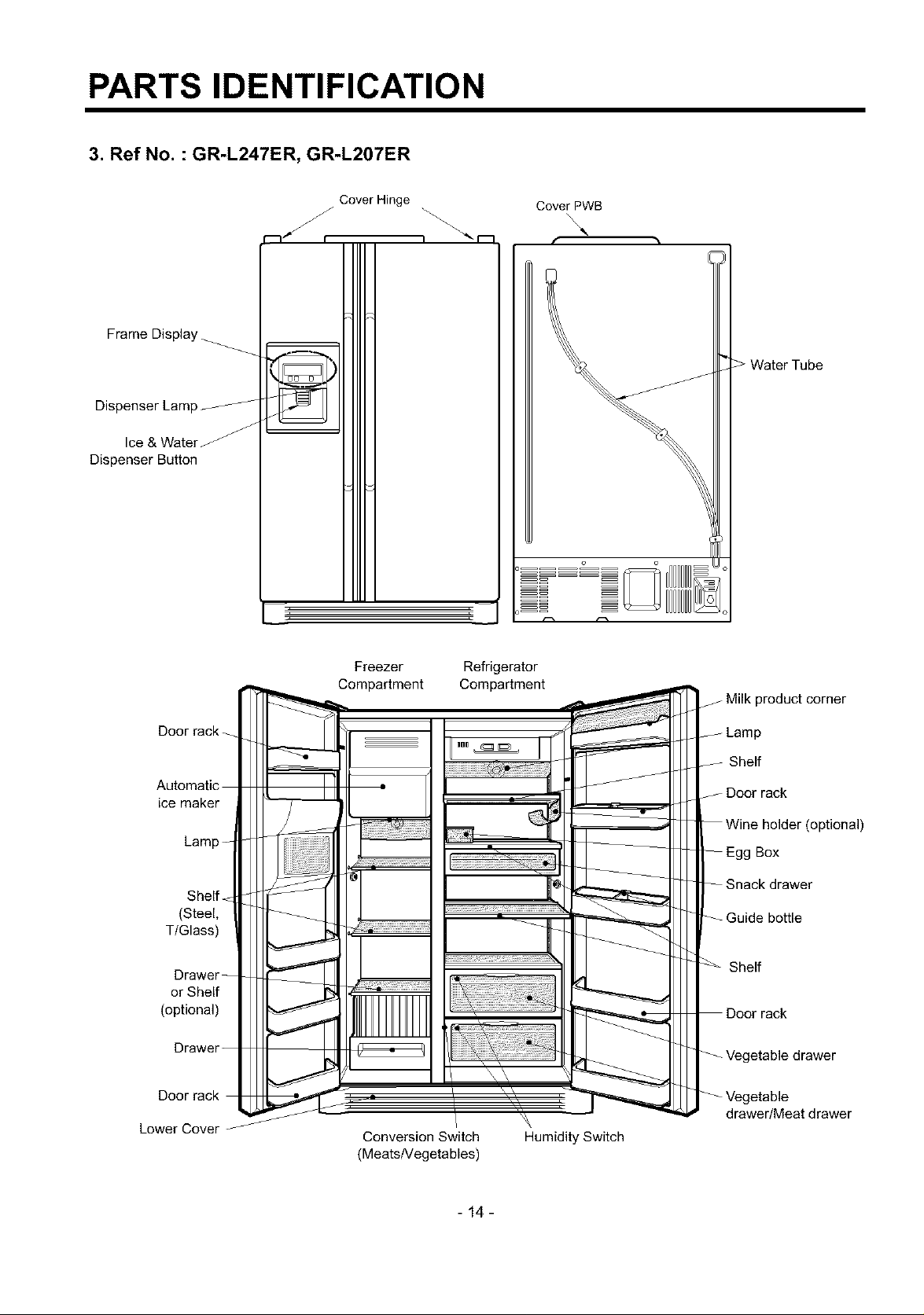
3. Ref No. : GR-L247ER, GR-L207ER
Frame Display
Dispenser Lamp
Dispenser Button
Cover Hinge
Cover PWB
Door rack
ice maker
Shelf
(Steel,
TIGlass)
Drawer
or Shelf
(optional)
Lower Cover
Freezer
Compartment
Conversion Switch
(MeatsNegetables)
Refrigerator
Compartment
f Milk product corner
Shelf
J Door rack
(optional)
Box
drawer
Shelf
rack
drawer/Meat drawer
Humidity Switch
-14-
HOW TO INSTALL REFRIGERATOR
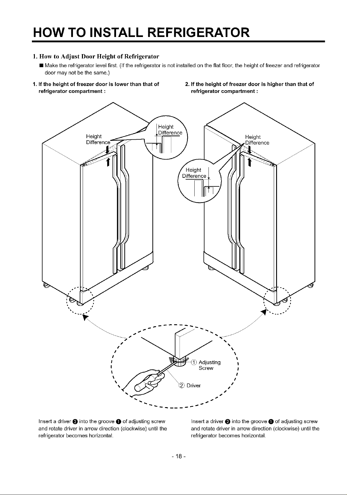
1. How to Adjust Door Height of Refrigerator
• Make the refrigerator levelfirst. (If the refrigerator is notinstalled on the flat floor, the height of freezer and refrigerator
door may not be the same.)
1. If the height of freezer door is lower than that of
refrigerator compartment :
Height
Difference'
2. If the height of freezer door is higher than that of
refrigerator compartment :
Height
Difference
Insert a driver 0 into the groove O of adjusting screw
and rotate driver in arrow direction (clockwise) until the
refrigerator becomes horizontal.
Insert a driver 0 into the groove O of adjusting screw
and rotate driver in arrow direction (clockwise) until the
refrigerator becomes horizontal.
-18-
HOW TO INSTALL REFRIGERATOR
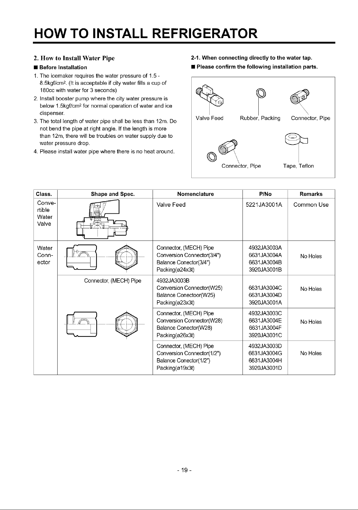
2. How to Install Water Pipe
• Before Installation
1. The icemaker requires the water pressure of 1.5
8.5kgf/cm 2. (It is acceptable if city water fills a cup of
180cc with water for 3 seconds)
2. Install booster pump where the city water pressure is
below 1,5kgf/cm 2for normal operation of water and ice
dispenser.
3. The total length of water pipe shall be less than 12m, Do
not bend the pipe at right angle. If the length is more
than 12m, there will be troubles on water supply due to
water pressure drop.
4. Please install water pipe where there is no heat around.
Class,
Conve-
rtible
Water
Valve
Shape and Spec.
Valve Feed
2-1. When connecting directly to the water tap.
• Please confirm the following installation parts,
Valve Feed Rubber, Packing Connector, Pipe
Connector, Pipe Tape, Teflon
Nomenclature
P/No
5221JA3001A
Remarks
Common Use
Water
Conn-
ector
Connector, (MECH) Pipe
Connector,(MECH)Pipe
ConversionConnector(3/4")
BalanceCenector(3/4")
Packing(e24x3t)
4932JA3003A
6631JA3004A
6631JA3004B
3920JA3001B
NoHoles
4932JA3003B
ConversionConnector(W25)
BalanceConectoor(W25)
Packing(e23x3t)
6631JA3004C
6631JA3004D
3920JA3001A
NoHoles
Connector,(MECH)Pipe 4932JA3003C
ConversionConnector(W28) 6631JA3004E NoHoles
BalanceConector(W28) 6631JA3004F
Packing(e26x3t) 3920JA3001C
Connector,(MECH)Pipe
ConversionConnector(I/2")
BalanceConector(1/2")
Packing(e19x3t)
4932JA3003D
6631JA3004G
6631JA3004H
3920JA3001D
NoHoles
-19-
HOW TO INSTALL REFRIGERATOR
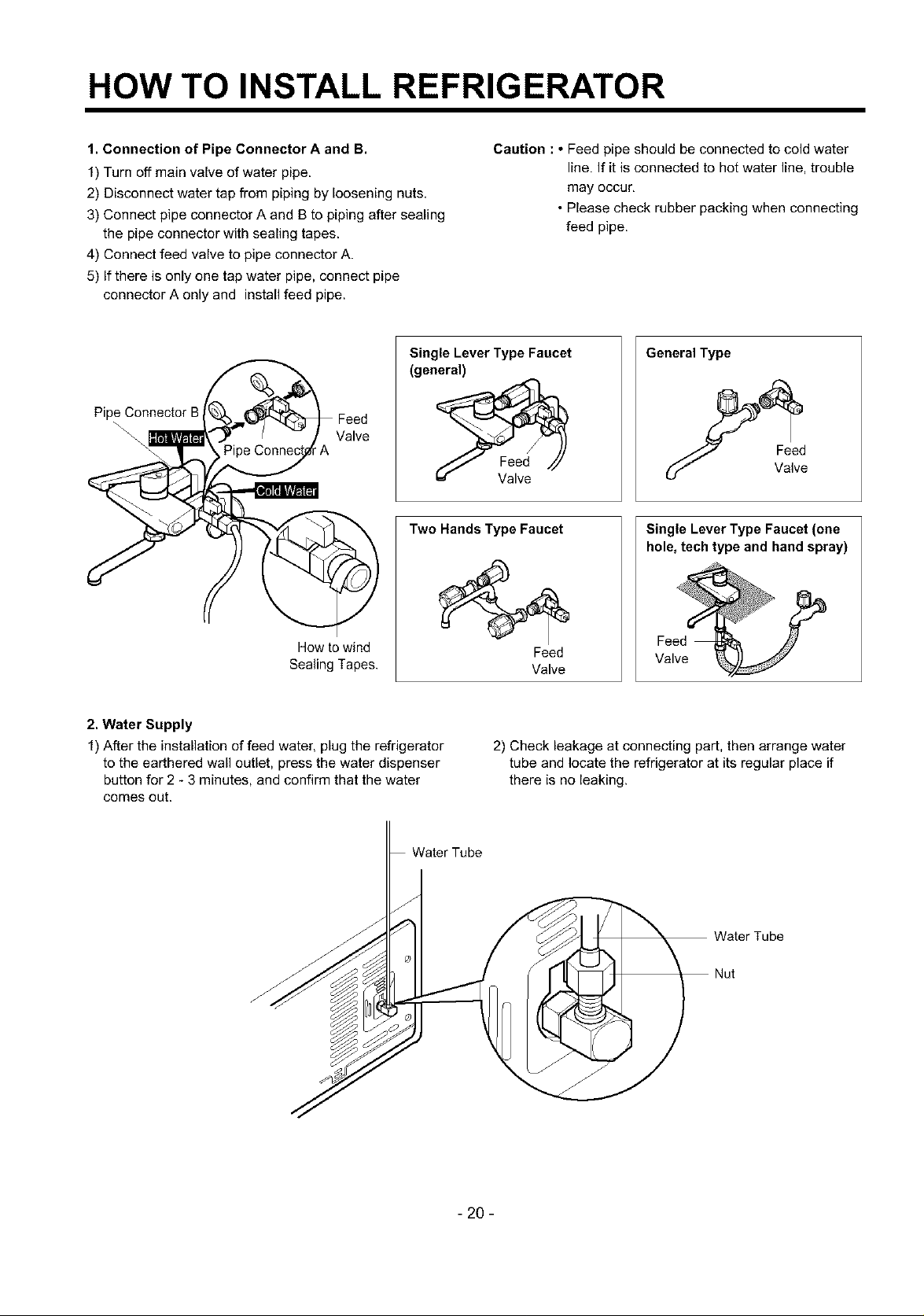
1. Connection of Pipe Connector A and B.
1) Turn off main valve of water pipe.
2) Disconnect water tap from piping by loosening nuts,
3) Connect pipe connector A and B to piping after sealing
the pipe connector with sealing tapes.
4) Connect feed valve to pipe connector A.
5) If there is only one tap water pipe, connect pipe
connector A only and install feed pipe.
Single Lever Type Faucet
(general)
Pipe Connector B
\\
\
Valve
Two Hands Type Faucet
Caution : • Feed pipe should be connected to cold water
line. If it is connected to hot water line, trouble
may occur,
• Please check rubber packing when connecting
feed pipe.
General Type
Single Lever Type Faucet (one
hole, tech type and hand spray)
How to wind
Sealing Tapes.
2. Water Supply
1) After the installation of feed water, plug the refrigerator
to the earthered wall outlet, press the water dispenser
button for 2 - 3 minutes, and confirm that the water
comes out,
Water Tube
f
Feed
Valve
2) Check leakage at connecting part, then arrange water
tube and locate the refrigerator at its regular place if
there is no leaking.
Feed
Valve
Nut
- 20 -
HOW TO INSTALL REFRIGERATOR
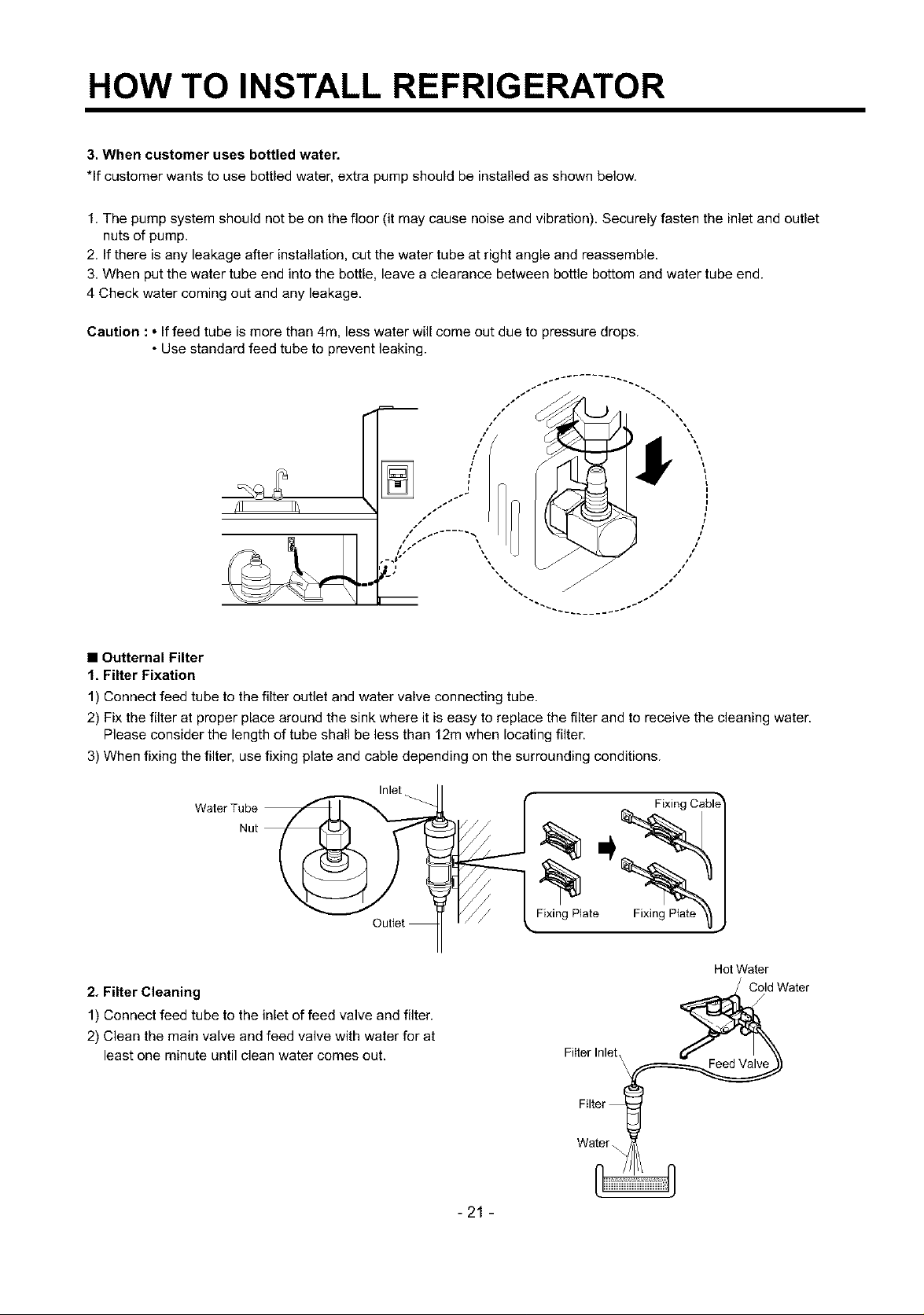
3. When customer uses bottled water.
*If customer wants to use bottled water, extra pump should be installed as shown below.
1. The pump system should not be on the floor (it may cause noise and vibration). Securely fasten the inlet and outlet
nuts of pump.
2. If there is any leakage after installation, cut the water tube at right angle and reassemble.
3, When put the water tube end into the bottle, leave a clearance between bottle bottom and water tube end.
4 Check water coming out and any leakage.
Caution : • If feed tube is more than 4m, less water will come out due to pressure drops.
• Use standard feed tube to prevent leaking.
• Outternal Filter
1, Filter Fixation
1) Connect feed tube to the filter outlet and water valve connecting tube.
2) Fix the filter at proper place around the sink where it is easy to replace the filter and to receive the cleaning water.
Please consider the length of tube shall be less than 12m when locating filter.
3) When fixing the filter, use fixing plate and cable depending on the surrounding conditions.
Inlet
Water Tube
Nut
FixingPlate
Hot Water
2. Filter Cleaning
1) Connect feed tube to the inlet of feed valve and filter.
2) Clean the main valve and feed valve with water for at
least one minute until clean water comes out.
Filter Inlet,
\
Cold Water
Feed Valve
-21 -
Water
HOW TO INSTALL REFRIGERATOR
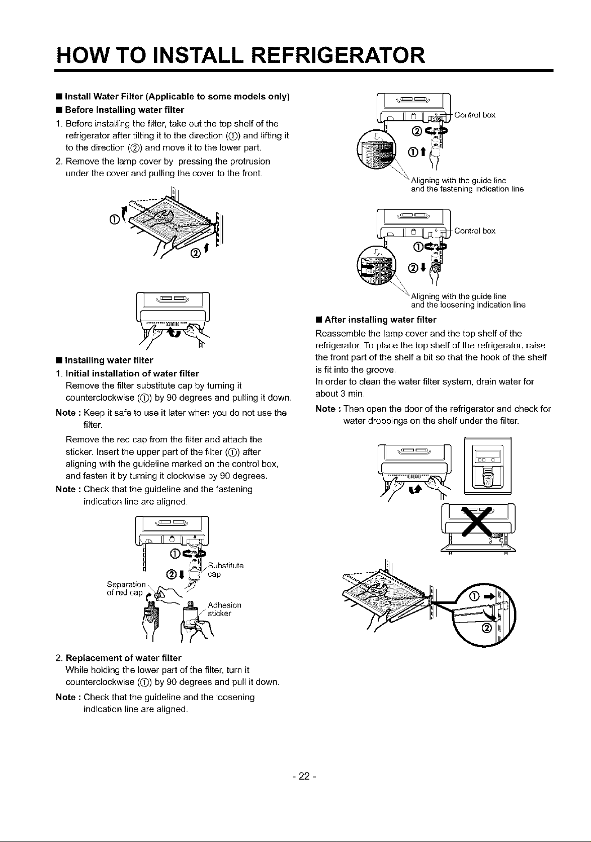
• Install Water Filter (Applicable to some models only)
• Before Installing water filter
1. Before installing the filter, take out the top shelf of the
refrigerator after tilting it to the direction (Q) and lifting it
to the direction (@) and move it to the lower part,
2. Remove the lamp cover by pressing the protrusion
under the cover and pulling the cover to the front.
[11 q
_'J_ Aligni_lgwith the guide line
IIl IIJ
• Installing water filter
1. Initial installation of water filter
Remove the filter substitute cap by turning it
counterclockwise ((D) by 90 degrees and pulling it down.
Note : Keep it safe to use it later when you do not use the
filter.
Remove the red cap from the filter and attach the
sticker. Insert the upper part of the filter ((!)) after
aligning with the guideline marked on the control box,
and fasten it by turning it clockwise by 90 degrees.
Note : Check that the guideline and the fastening
indication line are aligned.
• After installing water filter
Reassemble the lamp cover and the top shelf of the
refrigerator. To place the top shelf of the refrigerator, raise
the front part of the shelf a bit so that the hook of the shelf
is fit into the groove.
In order to clean the water filter system, drain water for
about 3 min.
Note : Then open the door of the refrigerator and check for
water droppings on the shelf under the filter.
Control box
Aligning with the guide line
and the fastening indication line
Contro,box
and the loosening indication line
Substitute
ap
Separation_ _
of red cap____ _Aidchkes'i°n
2. Replacement of water filter
While holding the lower part of the filter, turn it
counterclockwise ((D) by 90 degrees and pull it down.
Note : Check that the guideline and the loosening
indication line are aligned.
- 22 -
HOW TO INSTALL REFRIGERATOR
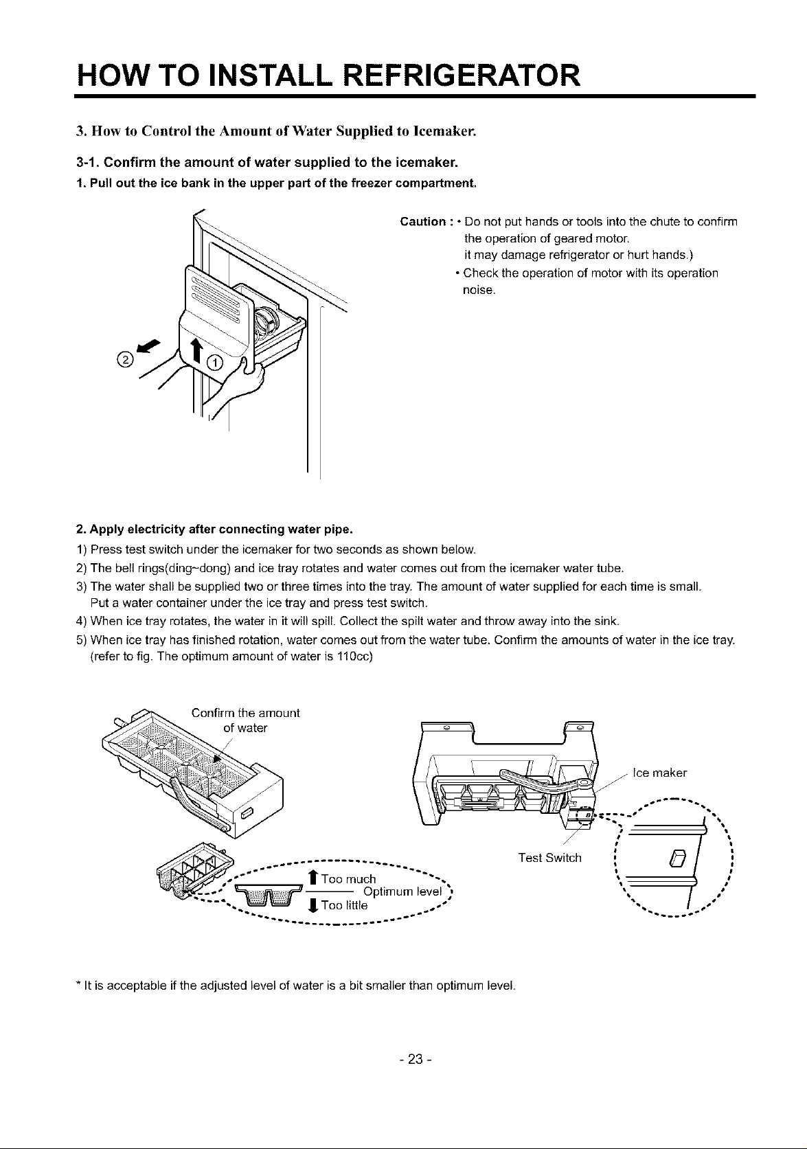
3. How to Control the Amount of Water Supplied to lcemaker.
3-1. Confirm the amount of water supplied to the icemaker.
1, Pull out the ice bank in the upper part of the freezer compartment.
Caution : • Do not put hands or tools into the chute to confirm
the operation of geared motor.
it may damage refrigerator or hurt hands.)
• Check the operation of motor with its operation
noise.
2. Apply electricity after connecting water pipe.
1) Press test switch under the icemaker for two seconds as shown below.
2) The bell rings(ding-dong) and ice tray rotates and water comes out from the icemaker water tube.
3) The water shall be supplied two or three times into the tray. The amount of water supplied for each time is small.
Put a water container under the ice tray and press test switch.
4) When ice tray rotates, the water in it will spill. Collect the spilt water and throw away into the sink.
5) When ice tray has finished rotation, water comes out from the water tube. Confirm the amounts of water in the ice tray.
(refer to fig. The optimum amount of water is 110cc)
Confirm the amount
of water
Test Switch
Too much -.
_-" -- Optimum level )
-.. -- _oo _lL_e ,,
Pq
ice maker
* it is acceptable if the adjusted level of water is a bit smaller than optimum level.
- 23 -
HOW TO INSTALL REFRIGERATOR
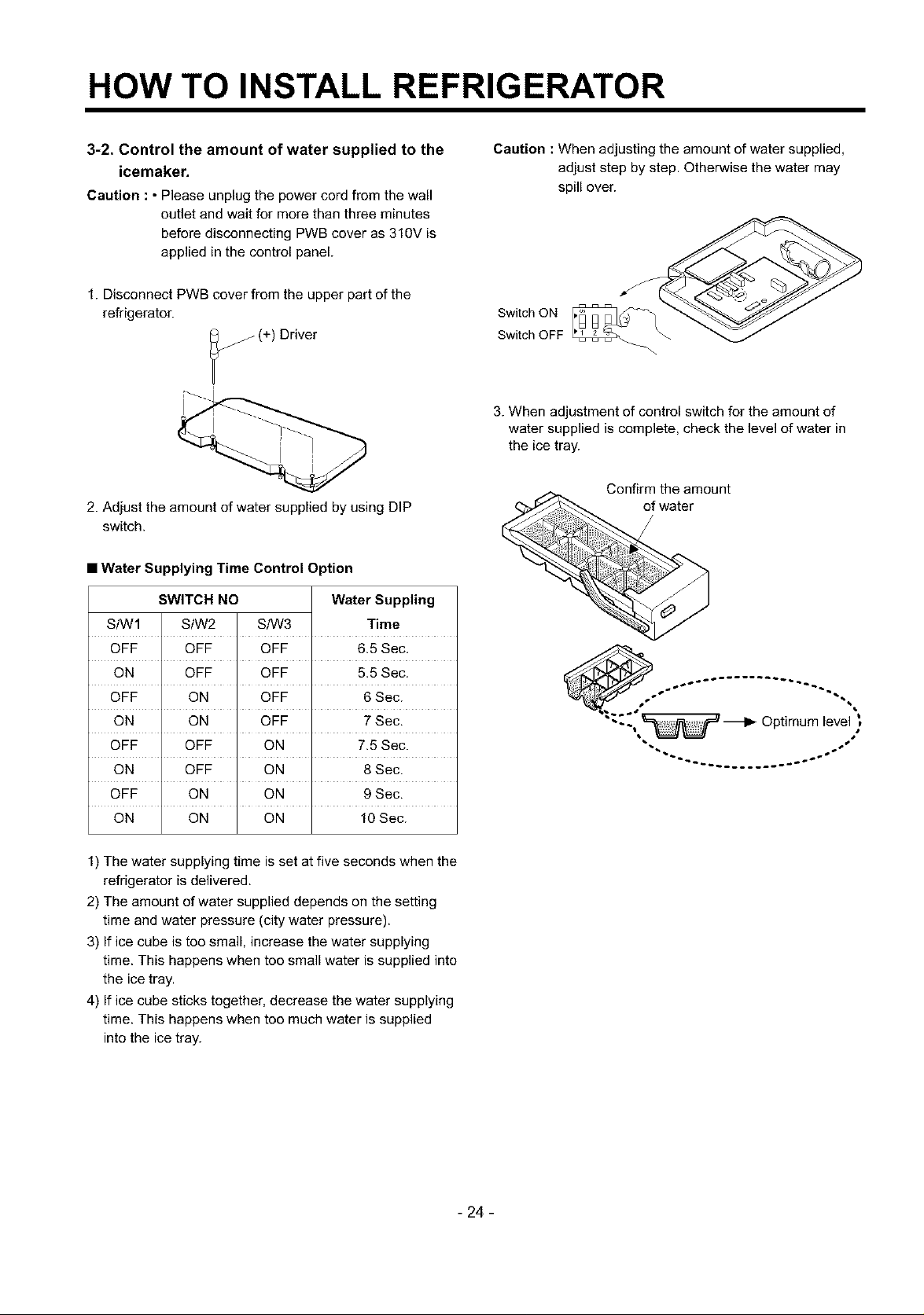
3-2. Control the amount of water supplied to the
icemaker.
Caution : • Please unplug the power cord from the wall
outlet and wait for more than three minutes
before disconnecting PWB cover as 310V is
applied in the control panel.
1. Disconnect PWB cover from the upper part of the
refrigerator.
(+) Driver
2. Adjust the amount of water supplied by using DIP
switch.
• Water Supplying Time Control Option
SWITCH NO Water Suppling
StWl S/W2 S/W3 Time
OFF OFF OFF 6.5 Sec.
ON OFF OFF 5.5 Sec.
OFF ON OFF 6 Sec.
ON ON OFF 7 Sec.
OFF OFF ON 7.5 Sec.
ON OFF ON 8 Sec.
OFF ON ON 9 Sec.
ON ON ON 10 Sec.
Caution :When adjusting the amount of water supplied,
adjust step by step. Otherwise the water may
spill over.
Switch ON
Switch OFF
3. When adjustment of control switch for the amount of
water supplied is complete, check the level of water in
the ice tray.
Confirm the amount
of water
"--~ _ Optimum level
1) The water supplying time is set at five seconds when the
refrigerator is delivered.
2) The amount of water supplied depends on the setting
time and water pressure (city water pressure).
3) If ice cube is too small, increase the water supplying
time. This happens when too small water is supplied into
the ice tray.
4) If ice cube sticks together, decrease the water supplying
time. This happens when too much water is supplied
into the ice tray.
- 24 -
MICOM FUNCTION
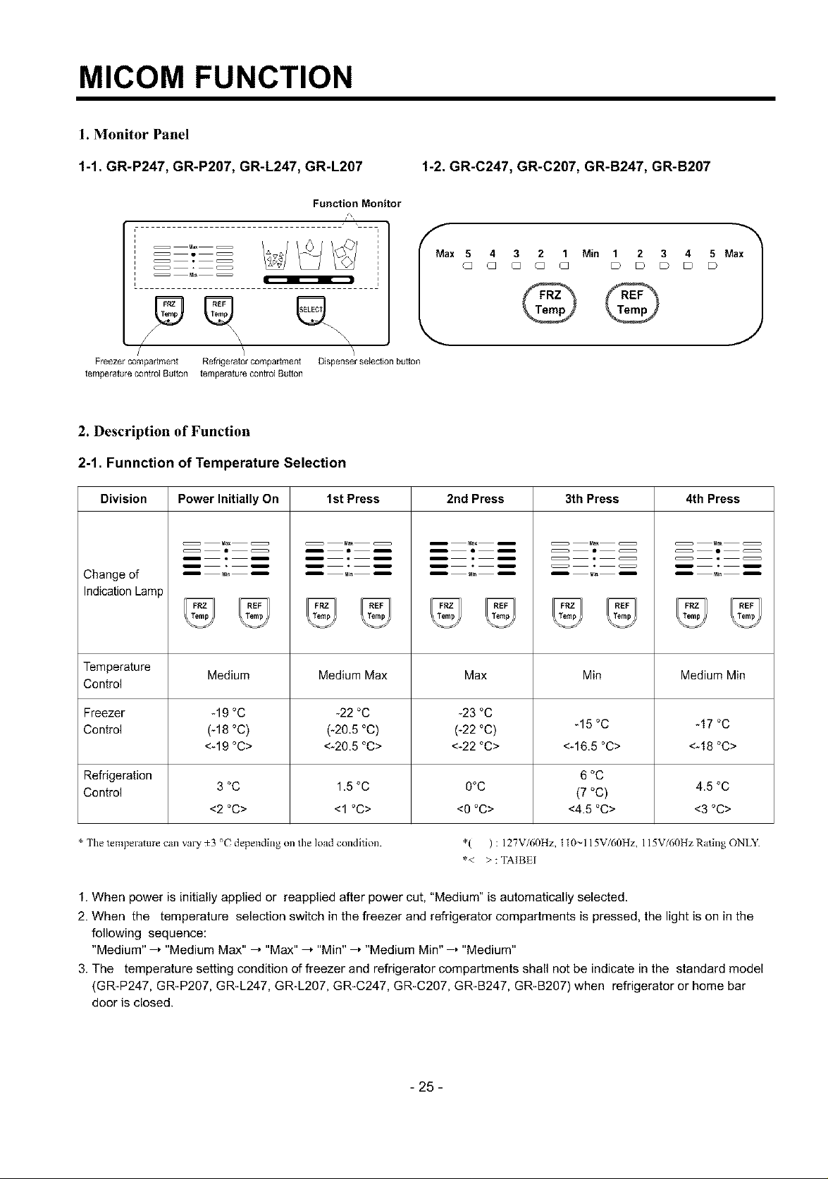
1. Monitor Panel
1-1. GR-P247, GR-P207, GR-L247, GR-L207 1-2. GR-C247, GR-C207, GR-B247, GR-B207
Function Monitor
4Q3 2 1 Min 1 2 3 4 5 Max
G
Q Q Q D D D D D
®® ®..
/ \ \_\
Freezer compartment Refrigerator compartment
temperature control Button temperature control Button
Dispenser selection button
ax 5
2. Description of Function
2-1. Funnction of Temperature Selection
Division
Change of
Indication Lamp
Temperature Medium Medium Max Max Min Medium Min
Control
Freezer -19 °C -22 °C -23 °C
Control (-18 °C) (-20.5 °C) (-22 °C) -15 °C -17 °C
Power Initially On 1st Press 2nd Press 3th Press 4th Press
<-19 °C> <-20.5 °C> <-22 °C> <-16.5 °C> <-18 °C>
J
Refrigeration 6 °C
Control 3 °C 1.5 °C O°C (7 °C) 4.5 °C
<2 °C> <1 °C> <O°C> <4.5 °C> <3 °C>
* The temperature call valy _3 °( depending on tileload condition. *( ) : 127V/60Hz, t t0~115V/60Hz, 115V/60HzRating ONLY.
*< >: TAIBEI
1. When power is initially applied or reapplied after power cut, "Medium" is automatically selected.
2. When the temperature selection switch in the freezer and refrigerator compartments is pressed, the light is on in the
following sequence:
"Medium" , "Medium Max" , "Max" .'"Min" , "Medium Min" , "Medium"
3. The temperature setting condition of freezer and refrigerator compartments shall not be indicate in the standard model
(GRIP247, GRIP207, GR_L247, GR-L207, GR-C247, GR_C207, GR-B247, GR-B207) when refrigerator or home bar
door is closed.
- 25-
MICOM FUNCTION
2-2. Automatic ice maker
• The automatic ice maker can automatically make 8 pieces of ice cube at a time, 80 pieces a day. But these quantities may
be varied according to various conditions including how many times the refrigerator door opens and closes.
• Ice making stops when the ice storage bin is full.
• If you don't want to use automatic ice-maker, change the ice-maker switch to ON-OFF.
If you want to use automatic ice-maker again, change the switch to OFF-ON.
NOTE : It is normal that a noise is produced when ice made is dropped into the ice storage bin.
2-3. When ice maker does not operate smoothly
Ice is lumped together
• When ice is lumped together, take the ice lumps out of the ice storage bin, break them into small pieces, and then place
them into the ice storage bin again.
• When the ice maker produces too small or lumped together ice, the amount of water supplied to the ice maker need to
adjusted. Contact the service center.
;{-"If ice is not used frequently, it may lump together.
Power failure
• Ice may drop into the freezer compartment. Take the ice storage bin out and discard all the ice then dry it and place it
back. After the machine is powered again, crushed ice will be automatically selected.
The unit is newly installed
• It takes about 12 hours for a newly installed refrigerator to make ice in the freezer compartment.
- 26 -
MICOM FUNCTION
2-4. Control of variable type of freezing room fan
1. To increase cooling speed and load response speed, MICOM variably controls freezing room fan motor at the high speed
of RPM and standard RPM.
2. MICOM only operates in the input of initial power or special freezing operation or load response operation for the high
speed of RPM and operates in the standard RPM in other general operation,
3. If opening doors of freezing / cold storage room or home bar while fan motor in the freezing room operates, the freezing
room fan motor normally operates (If being operated in the high speed of RPM, it converts operation to the standard
RPM). However, if opening doors of freezing room or home bar, the freezing room fan motor stops.
4. As for monitoring of BLDC fan motor error in the freezing room, MICOM immediately stops the fan motor by determining
that the BLDC fan motor is locked or poor if there would be position signal for more than 65 seconds at the BLDC motor.
Then it displays failure (refer to failure diagnosis function table) at the display part of refrigerator, performs re-operation in
the cycle of 30 minutes. If normal operation is performed, poor status is released and refrigerator returns to the initial
status (reset).
2-5. Control of M/C room fan motor
1. The M/C room fan motor performs ONIOFF control by linking with the COMP.
2. It controls at the single RPM without varying RPM.
3. Failure sensing method is same as in fan motor of freezing fan motor (refer to failure diagnosis function table for failure
display).
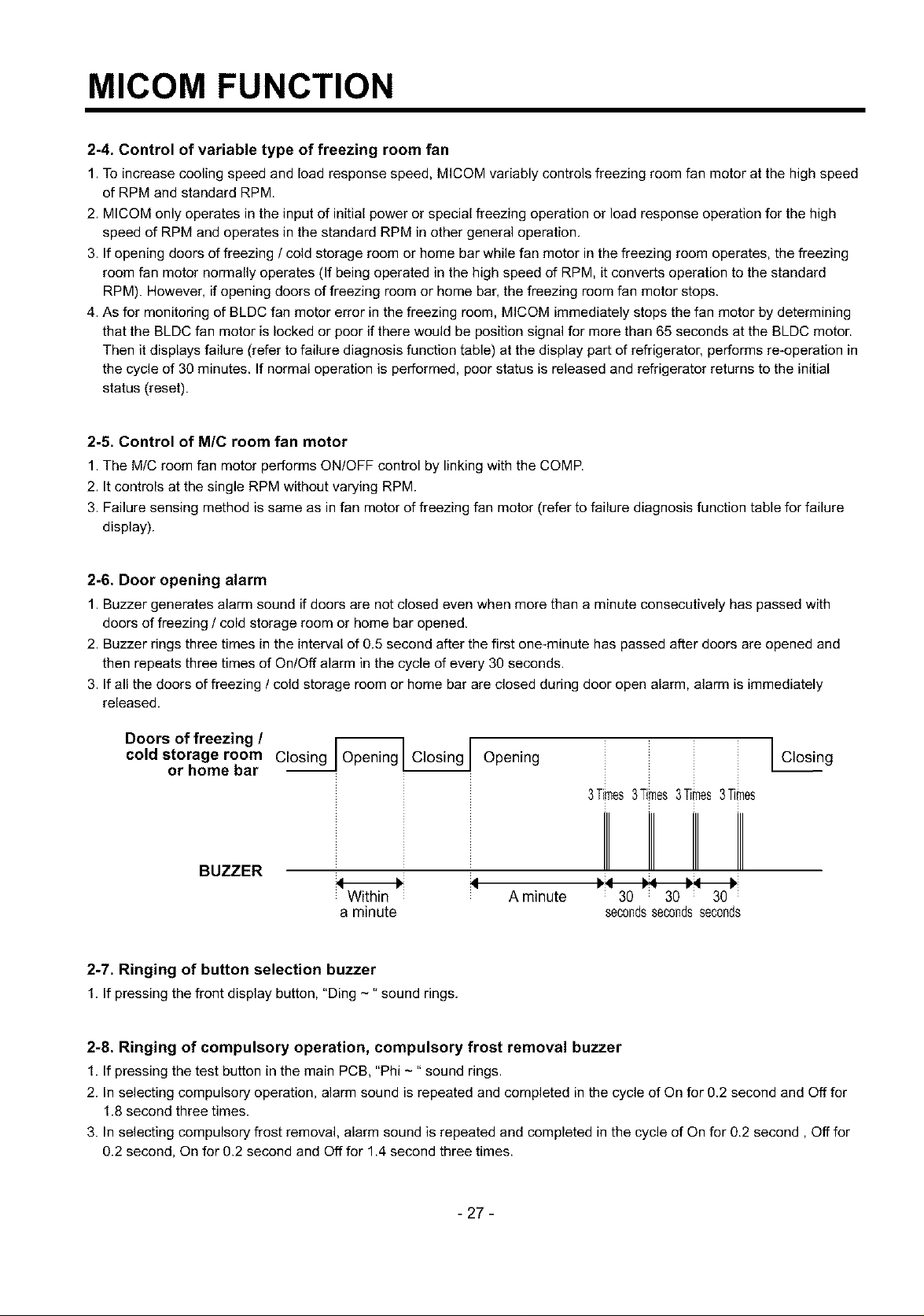
2-6. Door opening alarm
1. Buzzer generates alarm sound if doors are not closed even when more than a minute consecutively has passed with
doors of freezing / cold storage room or home bar opened,
2. Buzzer rings three times in the interval of 0.5 second after the first one-minute has passed after doors are opened and
then repeats three times of On/Off alarm in the cycle of every 30 seconds.
3. If all the doors of freezing / cold storage room or home bar are closed during door open alarm, alarm is immediately
released.
Doors of freezing / r_l i
cold storage room C_Openin_ Opening
or home bar
I Closing
3Times3Times3Times3Times
BUZZER
H :_
Within A minute
a minute
: 30 i 30 i 30
secondssecondsseconds
2-7. Ringing of button selection buzzer
1.If pressing the front display button, "Ding -" sound rings.
2-8. Ringing of compulsory operation, compulsory frost removal buzzer
1. If pressing the test button in the main PCB, "Phi - " sound rings.
2. In selecting compulsory operation, alarm sound is repeated and completed in the cycle of On for 0.2 second and Off for
1.8 second three times.
3. In selecting compulsory frost removal, alarm sound is repeated and completed in the cycle of On for 0.2 second, Off for
0.2 second, On for 0.2 second and Off for 1.4 second three times.
- 27-
MICOM FUNCTION
2-9. Frost removal function
1. Frost removal is performed whenever total operation time of compressor becomes 7 - 7.5 hour.
2. In providing initial power (or returning power failure), frost removal starts whenever total operation time of compressor
becomes 4 - 4.5 hour.
3. Frost removal is completed if temperature of a frost removal sensor becomes more than 5°C after starting frost removal.
Poor frost removal is not displaced if it does not arrive at 5°C even if two hours have passed after starting frost removal.
4. No removal is done if frost removal sensor becomes poor (snapping or short-circuit).
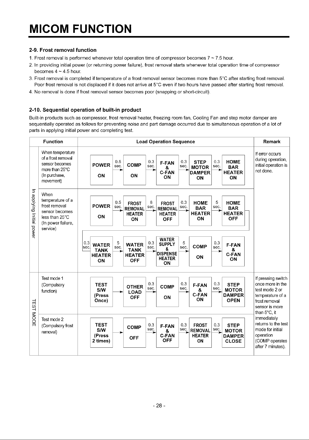
2-10. Sequential operation of built-in product
Built-in products such as compressor, frost removal heater, freezing room fan, Cooling Fan and step motor damper are
sequentially operated as follows for preventing noise and part damage occurred due to simultaneous operation of a lot of
parts in applying initial power and completing test.
Function Load Operation Sequence Remark
When temperature
ofa frost removal
sensorbecomes
morethan25°0
(Inpurchase,
movement)
When
__ temperature of a
"_- frost removal
sensor becomes
Iessthan 25°0
_-- (In powerfailure,
service)
e
Testmode 1
(Compulsory
function)
m
Testmode2
o
m
(Compulsoryfrost
removal)
POWER sec COMP sec & sec MOTOR sec BAR
ON ON ON ON ON
POWER sec REMOVAL sec REMOVAL sec BAR sec BAR
ON
03 WATER 5 WATER 03 SUPPLY 5 03 F-FAN
_ec TANK _ TANK _ _ _ &
HEATER HEATER DISPENSE C-FAN
ON OFF HEATER ON ON
TEST OTHER sec COMP sec & sec MOTOR
S/W _ LOAD _ _
(Press OFF ON C-FAN DAMPER
Once) ON OPEN
TEST COMP sec. sec.
S/W _ _ & _ REMOVAL% MOTOR
(Press OFF C-FAN HEATER DAMPER
2 times) OFF ON CLOSE
0.5 0.3 F-FAN 03 STEP 03 HOME
C-FAN DAMPER HEATER
05 FROST 8 FROST 03 HOME 5 HOME
HEATER HEATER HEATER HEATER
ON OFF ON OFF
WATER
sec. sec. & sec. COMP sec.
ON
0.3 03 F-FAN 03 STEP
0.3 F-FAN 0.3 FROST 0.3 STEP
Iferroroccurs
during operation,
initialoperation is
notdone.
Ifpressing switch
once more in the
test mode 2 or
temperature of a
frost removaI
sensor is more
than 5°C, it
immediately
returns to the test
mode for initial
operation
(COMP operates
after 7 minutes).
- 28 -
MICOM FUNCTION
2-15. Failure Diagnosis Function
1. Failure diagnosis function isfunction to facilitate service when nonconforming matters affecting performance of product
during use of product.
2. In occurrence of failure, pressing the function adjustment button does not perform function and only alarm sound ("Ding-") rings.
3. If nonconforming matters occurred are released during display of failure code, MICOM returns to the original state (Reset).
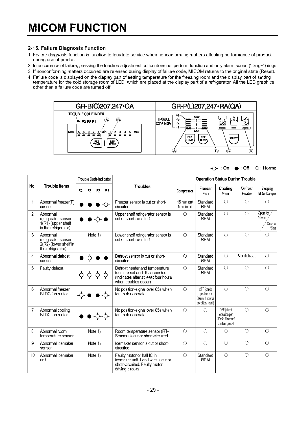
4. Failure code is displayed on the display part of setting temperature for the freezing room and the display part of setting
temperature for the cold storage room of LED, which are placed at the display part of a refrigerator. All the LED graphics
other than a failure code are turned off.
GR-B(C)207,247*CA
TROUBLE CODE INDEX
r 7
F4 F3 F2 F1
Max !S 4 3 2]l_M_n 1_2 _ 4 N Max
LI i i mllmj _l • B B
TroubleCodeIndicator Operation Status DuringTrouble
No, Trouble items Troubles Freezer Cooling Defrost Stepping
F4 F3 F2 Ff Compressor Fan Fan Heater MotorDamper
1 sensorAbn°rmalfreezer(F) • • •-_6- circuitedFreezersensoriscutor short- 115minoff5rainon/ StandardRPM © O ©
2 Abnormal Uppershelfrefrigeratorsensor is O Standard O O Openfcr/
refrigeratorsensor • •-¢-
I(Rf) (uppershelf • cut orshort-circuited. RPM
in the refrigerator)
3 Abnormal Note 1) Lowershelfrefrigeratorsensor is © Standard © © ©
refrigeratorsensor cut orshort-circuited. RPM
2(R2)(lowershelfin
the refrigerator)
4 Abnormaldefrost • _A_ • • Defrostsensoriscutor short- © Standard © Nodefrost ©
sensor Y circuited RPM
5 Faultydefrost Defrostheaterandtemperature © Standard © © ©
_¢__¢___¢_ fuse are cut and disconnected. RPM
6 Abnormalfreezer No position-signalover65swhen O 0FF(ch_ O O O
BLDCfan motor _¢_ • • _¢_ fan motoroperate @eat;®per
7 Abnormalcooling Noposition-signalover65swhen © O 0FF(ch_ O ©
BLDCfan motor • • _1(_¢_ fan motoroperate @eat;®per
8 Abnormalroom Note 1) Roomtemperaturesensor(RT- O O O O O
temperaturesensor Sensor) iscator short-circuited.
9 Abnormalicemaker Note 1) Icemakersensoris cut orshort- © O O O O
sensor circuited.
10 Abnormalicemaker Note 1) Faultymotor or hall ICin © Standard © © ©
unit icemakerunit.Leadwire is cutor RPM
K_7
(Indicatesafter atleastfourhours
when troublesoccur)
shotr-circuited.Faultymotor
drivingcircuits
GR-P(L)207,247.RA(O.A)
I"
-_- :On • :Off ©:Normal
30mi_7,_fn0rmal
c0ndr_®,reset}
30mi_7,_fn0rmal
®ndr_®,reset}
- 29 -
MICOM FUNCTION
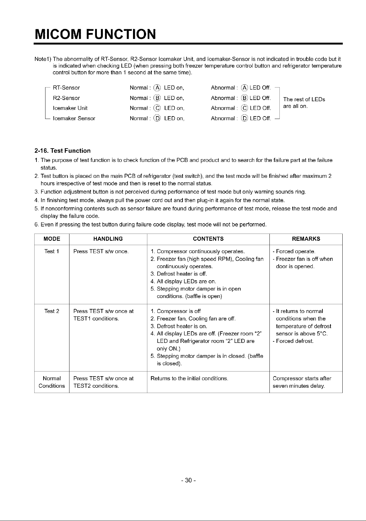
Note1) The abnormality of RT-Sensor, R2-Sensor Icemaker Unit, and Icemaker-Sensor is not indicated in trouble code but it
is indicated when checking LED (when pressing both freezer temperature control button and refrigerator temperature
control button for more than 1 second at the same time).
RT-Sensor
R2-Sensor
Icemaker Unit
Icemaker Sensor
Normal : (_ LED on,
Normal : _) LED on,
Normal : (_ LED on,
Normal : _) LED on,
Abnormal : (_) LED Off.
Abnormal : (_ LED Off.
Abnormal : (_ LED Off,
Abnormal : (_) LED Off.
The rest of LEDs
are all on.
2-16. Test Function
1. The purpose of test function is to check function of the PCB and product and to search for the failure part at the failure
status.
2. Test button is placed on the main PCB of refrigerator (test switch), and the test mode will be finished after maximum 2
hours irrespective of test mode and then is reset to the normal status.
3. Function adjustment button is net perceived during performance of test mode but only warning sounds ring.
4. In finishing test mode, always pull the power cord out and then plug-in it again for the normal state.
5. If nonconforming contents such as sensor failure are found during performance of test mode, release the test mode and
display the failure code.
6. Even if pressing the test button during failure code display, test mode will not be performed.
MODE
Test 1
Press TEST s/w once.
HANDLING
CONTENTS
1. Compressor continuously operates.
2. Freezer fan (high speed RPM), Cooling fan
continuously operates.
3. Defrost heater is off,
4. All display LEDs are on.
5. Stepping motor damper is in open
conditions. (baffle is open)
REMARKS
- Forced operate.
- Freezer fan is off when
door is opened.
Test 2
Normal Press TEST s/w once at Returns to the initial conditions. Compressor starts after
Conditions TEST2 conditions, seven minutes delay.
Press TEST s/w once at
TEST1 conditions.
1. Compressor is off
2. Freezer fan, Cooling fan are off.
3. Defrost heater is on.
4. All display LEDs are off. (Freezer room "2"
LED and Refrigerator room "2" LED are
only ON.)
5. Stepping motor damper is in closed. (baffle
is closed).
- It returns to normal
conditions when the
temperature of defrost
sensor is above 5°C.
- Forced defrost.
- 30 -
EXPLATION FOR MICOM CIRCUIT
1. Explanation for PWB circuit
%1. Power circuit
1, GR-L207ERA, GR-L247ERA, GR-B207ERA, GR-B247ERA
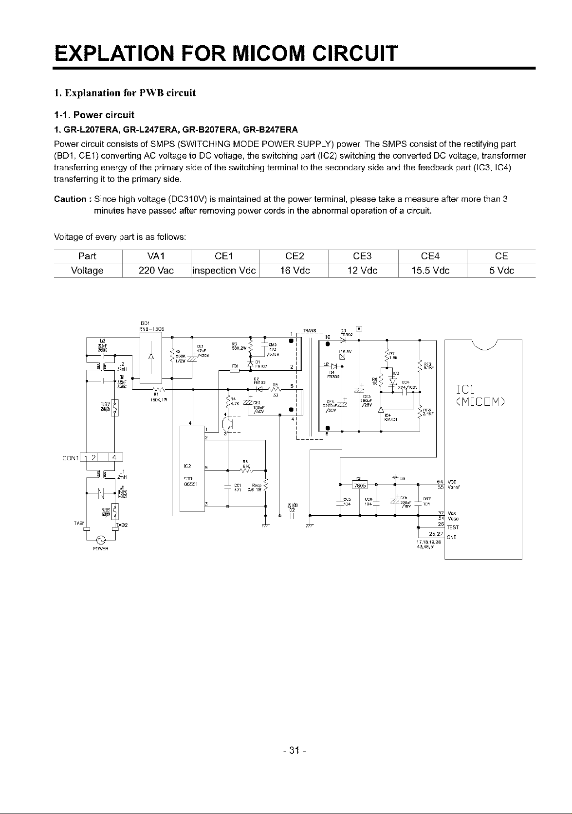
Power circuit consists of SMPS (SWITCHING MODE POWER SUPPLY) power. The SMPS consist of the rectifying part
(BD1, CE1) converting AC voltage to DC voltage, the switching part (IC2) switching the converted DC voltage, transformer
transferring energy of the primary side of the switching terminal to the secondary side and the feedback part (IC3, IC4)
transferring it to the primary side.
Caution :Since high voltage (DC310V) is maintained at the power terminal, please take a measure after more than 3
minutes have passed after removing power cords in the abnormal operation of a circuit.
Voltage ofevery part is as follows:
CE3 CE4 CE
Part VA1 CE1 Vdc CE2
Voltage 220 Vac inspection 16 Vdc
BDI
RVB 1506
1 F • I0 _3o2
]RANS D3
12 Vdc 15.5 Vdc 5 Vdc
÷
CON1
pOWER
_INR
L1
VAI
R1
15DK,1W
FBI 2 I _ ,>>RF2KF
FRI02 R5 I K % ; CO+
I<_ 5 i + 2 4 00v
I_ + 33 I + CE3
<,R4 C 2 I BS(]uF
"_7K IOOUF • I /2_V R_KF
4C7cl] 08RQlC_<" u - - 5£
43,48,51
/
IC1
(MICOM)
VDO
V_]ref
Vss
Wss
_ST
GNO
-31 -
EXPLATION FOR MICOM CIRCUIT
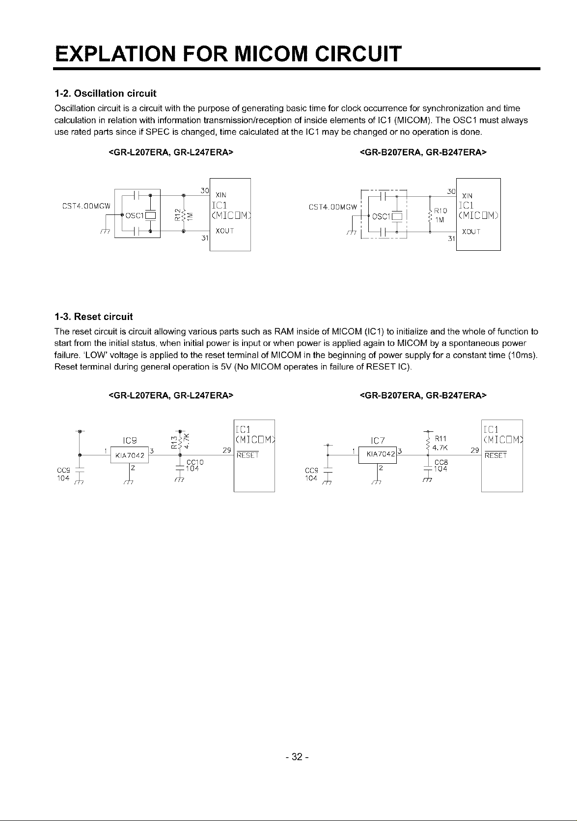
1-2. Oscillation circuit
Oscillation circuit is a circuit with the purpose of generating basic time for clock occurrence for synchronization and time
calculation in relation with information transmission/reception of inside elements of IC1 (MICOM). The OSC1 must always
use rated parts since if SPEC is changed, time calculated at the IC1 may be changed or no operation is done.
<GR-L207ERA, GR-L247ERA> <GR-B207ERA, GR-B247ERA>
50 XIN 30
XIN
ICI
(MICON o
XOUT
31 31
(HICON)
XOUT
1-3. Reset circuit
The reset circuit is circuit allowing various parts such as RAM inside of MICOM (IC1) to initialize and the whole of function to
start from the initial status, when initial power is input or when power is applied again to MICOM by a spontaneous power
failure. 'LOW' voltage is applied to the reset terminal of MICOM in the beginning of power supply for a constant time (10ms).
Reset terminal during general operation is 5V (No MICOM operates in failure of RESET IC).
<GR-L207ERA, GR-L247ERA> <GR-B207ERA, GR-B247ERA>
T cg [C1 _ml [Cl
_3 t CCIO 29 RESET •CC8 RESET
104CCg f717104 m[7104
_T_ (MICOP1} IC7 (NICON
_" 4 _4,7K 29
- 32 -
EXPLATION FOR MICOM CIRCUIT
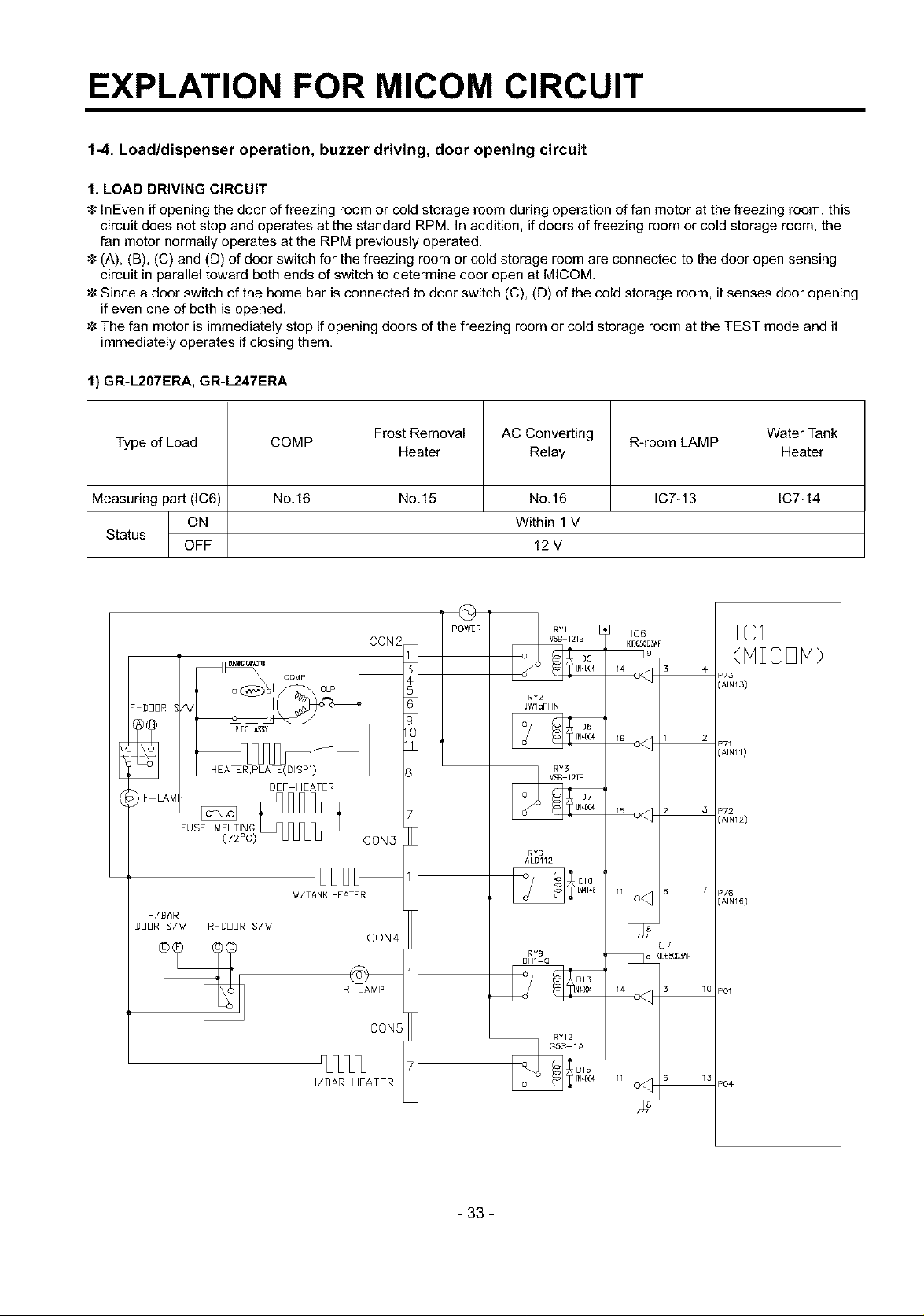
1-4. Load/dispenser operation, buzzer driving, door opening circuit
1. LOAD DRIVING CIRCUIT
InEven if opening the door of freezing room or cold storage room during operation of fan motor at the freezing room, this
circuit does not stop and operates at the standard RPM. In addition, if doors of freezing room or cold storage room, the
fan motor normally operates at the RPM previously operated.
(A), (B), (C) and (D) of door switch for the freezing room or cold storage room are connected to the door open sensing
circuit in parallel toward both ends of switch to determine door open at MICOM.
Since a door switch of the home bar is connected to door switch (C), (D) of the cold storage room, it senses door opening
if even one of both is opened.
The fan motor is immediately stop if opening doors of the freezing room or cold storage room at the TEST mode and it
immediately operates if closing them.
1) GR-L207ERA, GR-L247ERA
Type of Load COMP R-room LAMP
Frost Removal AC Converting Water Tank
Heater Relay Heater
Measuring part (IC6) No. 16 No. 15 No. 16 IC7-13 IC7-14
ON Within 1V
Status
OFF 12 V
pOWER
CON2
IC1
(HICDH)
P73
(AIN13)
P72
(AIN12)
DDDR S _7
PTC ASST
COMP
DEF HEATER
CON5
RY2
JWlaFHN
RY6
ALD112
H/BAR
DDDR S/'d R I]DDR S/'d
_4/TANK HEATER
R LAMP
H/BAR HEATER
CON4
CON5
- 33 -
RY9
OH] Q
RY12
_G5S ]A
D]3
D16
IC7
_k_OO3AP
P76
(AIN16)
P01
PO#
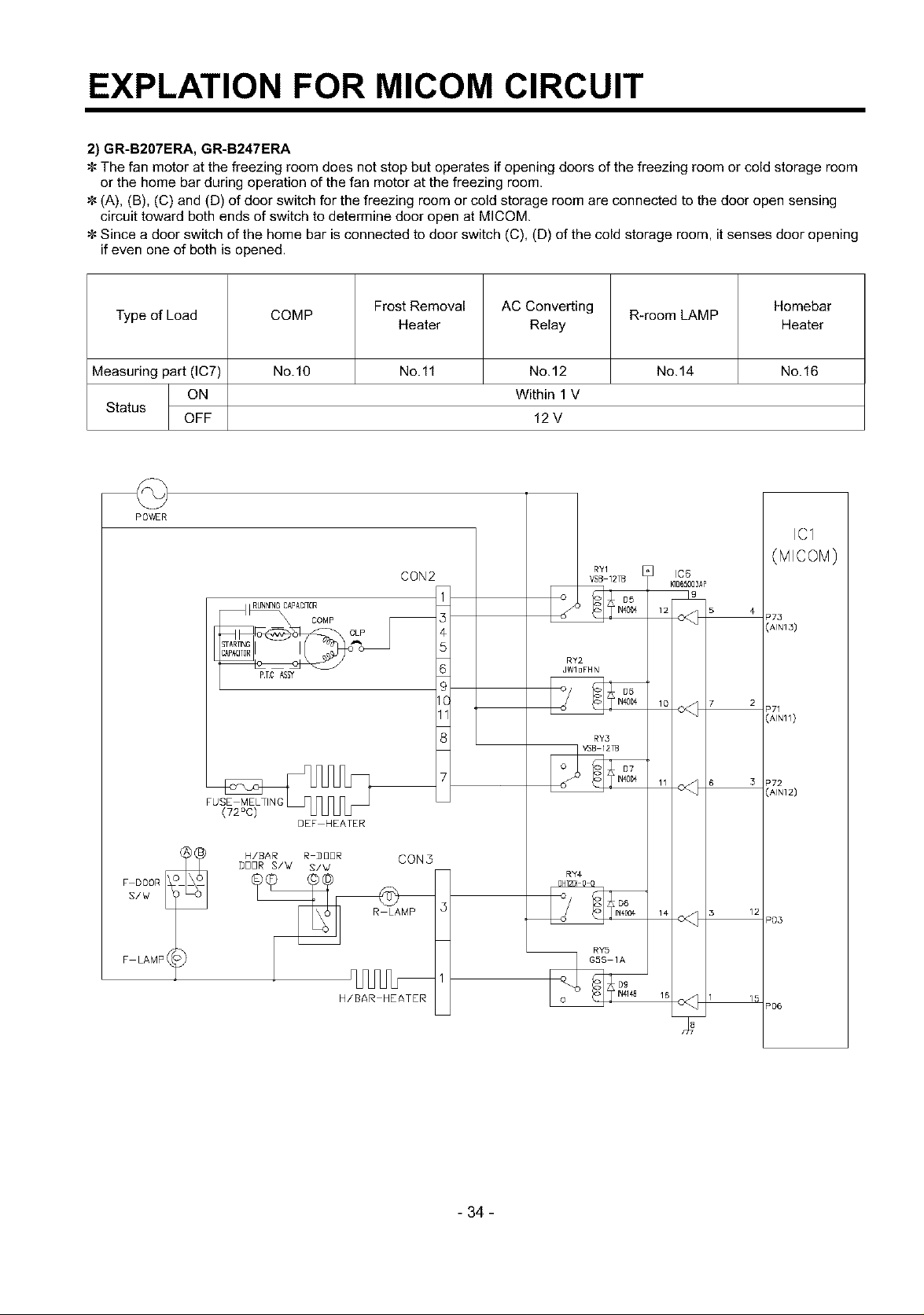
EXPLATION FOR MICOM CIRCUIT
2) GR-B207ERA, GR-B247ERA
The fan motor at the freezing room does not stop but operates if opening doors of the freezing room or cold storage room
or the home bar during operation of the fan motor at the freezing room.
(A), (B), (C) and (D) of door switch for the freezing room or cold storage room are connected to the door open sensing
circuit toward both ends of switch to determine door open at MICOM
Since a door switch of the home bar is connected to door switch (C), (D) of the cold storage room, it senses door opening
if even one of both is opened.
Type of Load COMP R-room LAMP
Frost Removal AC Converting Homebar
Heater Relay Heater
Measuring part (IC7) No.10 No.ll No.12 No.14 No.16
ON Within 1V
Status
POWER
OFF 12 V
IC1
CON2
_UNNNG CAPADFOR
P.TC AS_
COMP
F LAMP 4
DEF HEATER
H/B4R R _UUR CON3
BBBR S/W S/W
P03
P06
- 34 -
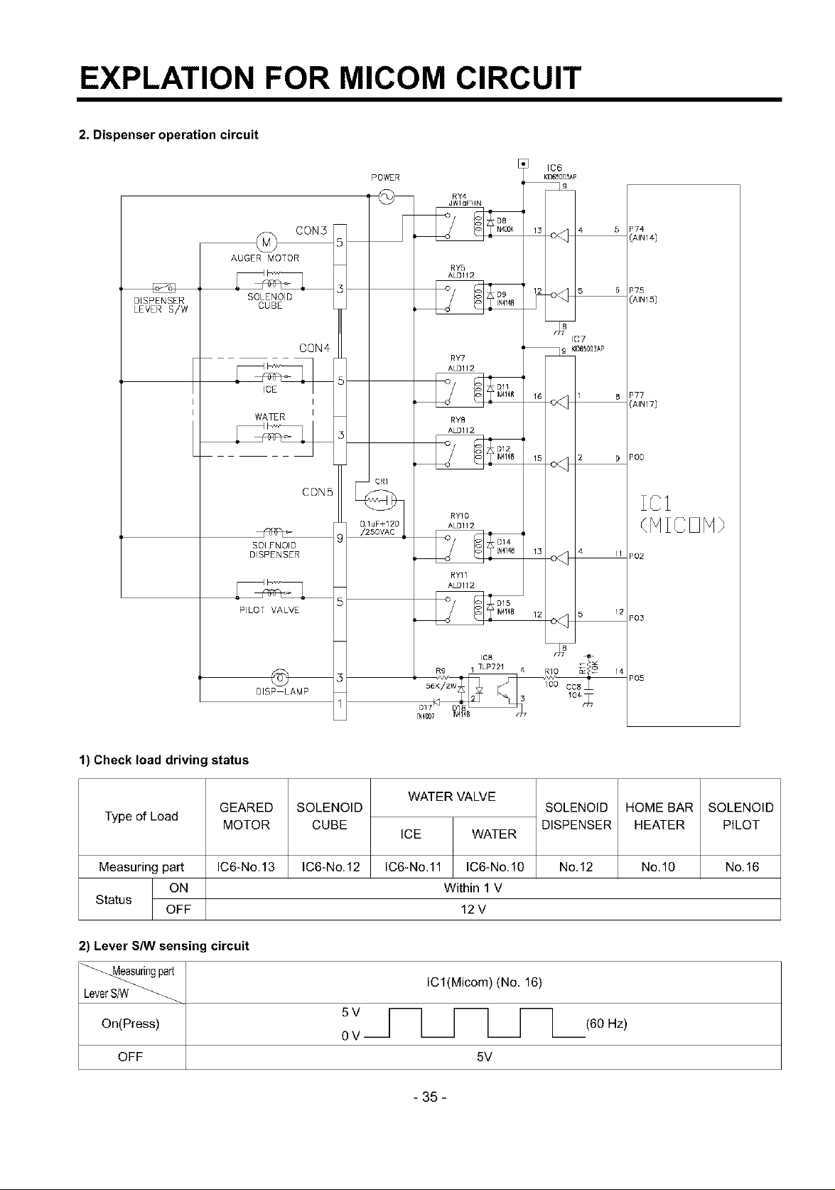
EXPLATION FOR MICOM CIRCUIT
2. Dispenser operation circuit
POWER
1
CON5
RY4
JWloF74N
DISPENSER
LEVER S/W
AUGER MOTOR
SOLENOID
CUBE
ICE
WA_R I
SOlYNOID
DISPENSER
PILOT VALVE
CON4
I
CONE
RY'a
ALD112
IC7
RY7
ALD112
Oll
RY8
ALS112
D12
CRI
RYIO
ALDll2
RYII
ALDI12
9 _D65003AP
I 8
15 2 9
13 4 11
12
"00
IC1
(NICDN}
"02
"03
OlSP LAMP
_@O7 _41€8
"05
1) Check load driving status
WATER VALVE
Type of Load
MOTOR
Measuring part IC6-No.13 IC6-No.12 No.12 No.10 No.16
GEARED
SOLENOID
CUBE
ICE WATER
IC6-No.ll IC6-No.10
SOLENOID
DISPENSER
HOMEBAR
HEATER
ON Within 1 V
Status
OFF 12 V
2) Lever S/W sensing circuit
_ing ICl(Micom) (No. 16)
part
LeverS/W
On(Press) (60 Hz)
0
OFF 5V
SOLENOID
PILOT
- 35-
EXPLATION FOR MICOM CIRCUIT
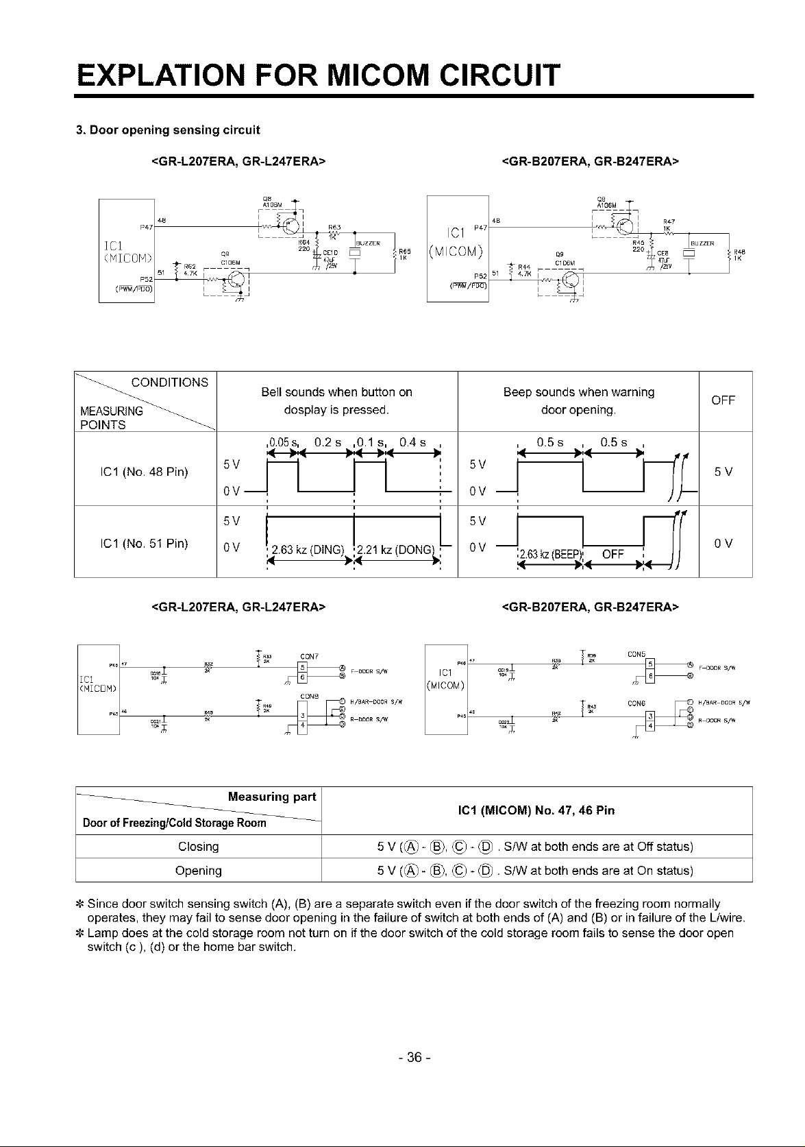
3. Door opening sensing circuit
<GR-L207ERA, GR-L247ERA> <GR-B207ERA, GR-B247ERA>
48
P47
ICI
(NICOM) Q_
P52 _v_
R62 C]06M
CB
_ R4.* C] D6M
51 " _TKF 1
P5;
09
_ CONDITIONS
_ Bell sounds when button on Beep sounds when warning OFF
MEASURING_ dosplay is pressed, door opening.
POINTS _-_
,O.05s,, 0.2s ....,0.1s, 0.4s ,j !., 0.5s ,.!., 0.5s
5V -- "' 5V
IC1 (No. 48 Pin)
0V
--, , T
0 V --,
5V
IC1 (No. 51 Pin)
0V ,2.63 kz (DING),..21 kz (DONG
0V --,2.63kz(BEEP), OFF ',
<GR-L207ERA, GR-L247ERA> <GR-B207ERA, GR-B247ERA>
5V
0V
CON5
F OOOR S/W
H/_AR DOOR S/W
R OOOR S/W
104_
_C21_
_ _ CON7
F 0OOR S/W
Measuring part
IC1 (MICOM) No. 47, 46 Pin
Doorof Freezing/ColdStorageRoom
Closing
Opening
5 V ((_)- _3), (_ (_. S/W at both ends are at Off status)
5 V ((_)_ _), (_ (_. S/W at both ends are at On status)
¢- Since door switch sensing switch (A), (B) are a separate switch even if the door switch of the freezing room normally
operates, they may fail to sense door opening in the failure of switch at both ends of (A) and (B) or in failure of the L/wire.
¢- Lamp does at the cold storage room not turn on if the door switch of the cold storage room fails to sense the door open
switch (c), (d) or the home bar switch.
- 36 -
EXPLATION FOR MICOM CIRCUIT
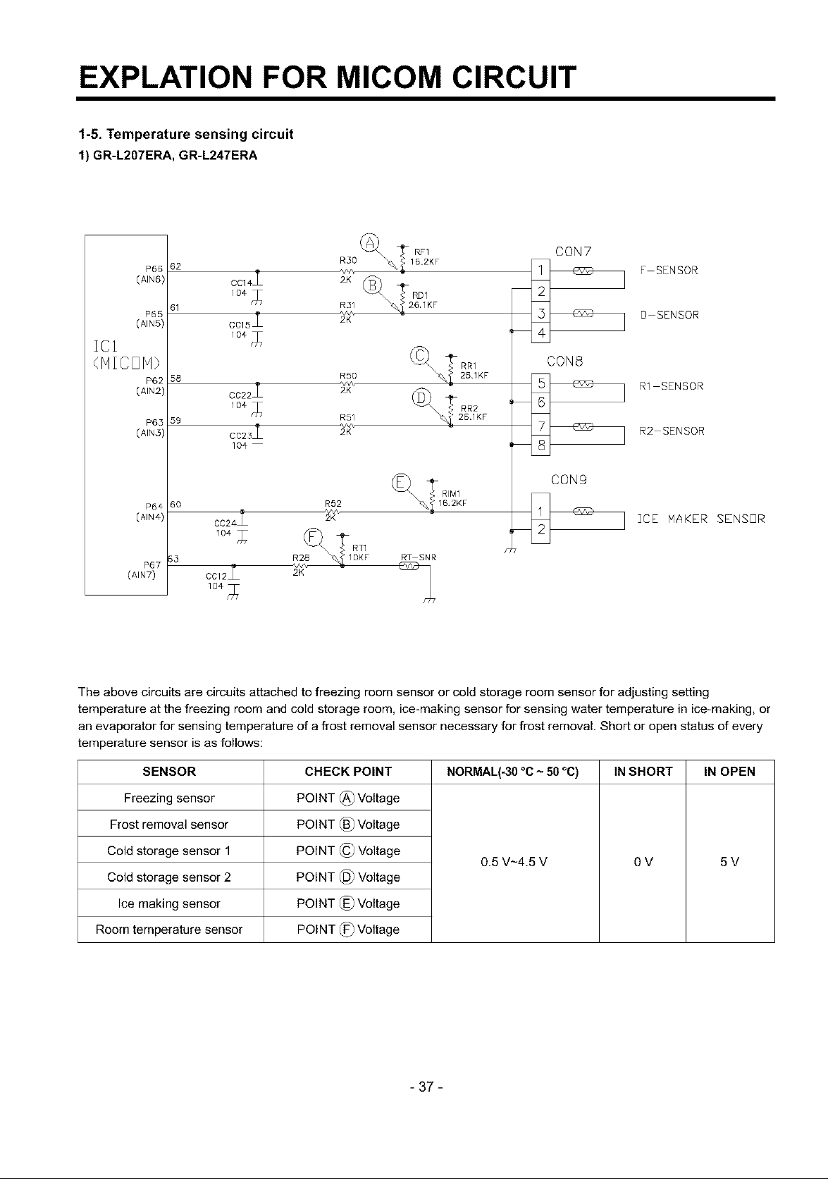
1-5. Temperature sensing circuit
1) GR-L207ERA, GR-L247ERA
zcl
(AIN6)
(AIN5)
(41N3)
(AIN4)
(AIN7)
62
P66
C 4I r
P65
58 RSO
5g R51
P65
6o
P64
P67
C015_ 2K D SENSOR
2 vv\
C022 2X
o023i
104
CC24 2K
104 _
CC12_ 2K
R30 _,_ 16.2KF F SENSOR
RF1 CON7
CON8
R1 SENSOR
R2 SENSOR
CON9
R92
ICE NAKER SENSOR
RT SNR
The above circuits are circuits attached to freezing room sensor or cold storage room sensor for adjusting setting
temperature at the freezing room and cold storage room, ice-making sensor for sensing water temperature in ice-making, or
an evaporator for sensing temperature of a frost removal sensor necessary for frost removal. Short or open status of every
temperature sensor is as follows:
SENSOR
Freezing sensor
Frost removal sensor
Cold storage sensor 1
Cold storage sensor 2
Ice making sensor
Room temperature sensor
CHECK POINT
POINT (_ Voltage
POINT (_) Voltage
POINT © Voltage
POINT 1_ Voltage
POINT 1_)Voltage
POINT 1_ Voltage
NORMAL(-30 °C ~ 50 °C) IN SHORT IN OPEN
0.5 V-4.5 V OV 5V
- 37 -
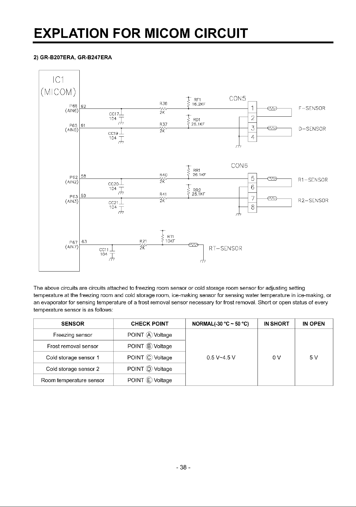
EXPLATION FOR MICOM CIRCUIT
2) GR-B207ERA, GR-B247ERA
ICI
MICOM)
P66
(AIN6)
62
CC17_ 2K
61 R57 _ 26.1KF
CC19_ 2K
R36
<_f:.RD1
*v,v%
,_RR1 CON 6
58 R4O
CC20 2K
59 R41
2 _v\
CC21 2K
10€n_ 7
T RT1
63 R21 _ IOKF
261KF
_261KF
CCl1_ _/K'_ - _ RT SENSOR
CON5
F SENSOR
D SENSOR
R1 SENSOR
R2 SENSOR
The above circuits are circuits attached to freezing room sensor or cold storage room sensor for adjusting setting
temperature at the freezing room and cold storage room, ice-making sensor for sensing water temperature in ice-making, or
an evaporator for sensing temperature of a frost removal sensor necessary for frost removal. Short or open status of every
temperature sensor is as follows:
SENSOR
Freezing sensor
Frost removal sensor
Cold storage sensor 1
Cold storage sensor 2
Room temperature sensor
CHECK POINT
POINT (_) Voltage
POINT (_) Voltage
POINT (_ Voltage
POINT @ Voltage
POINT (_) Voltage
NORMAL(-30 °C ~ 50 °C) IN SHORT IN OPEN
0.5 V_4.5 V OV 5V
- 38 -
EXPLATION FOR MICOM CIRCUIT
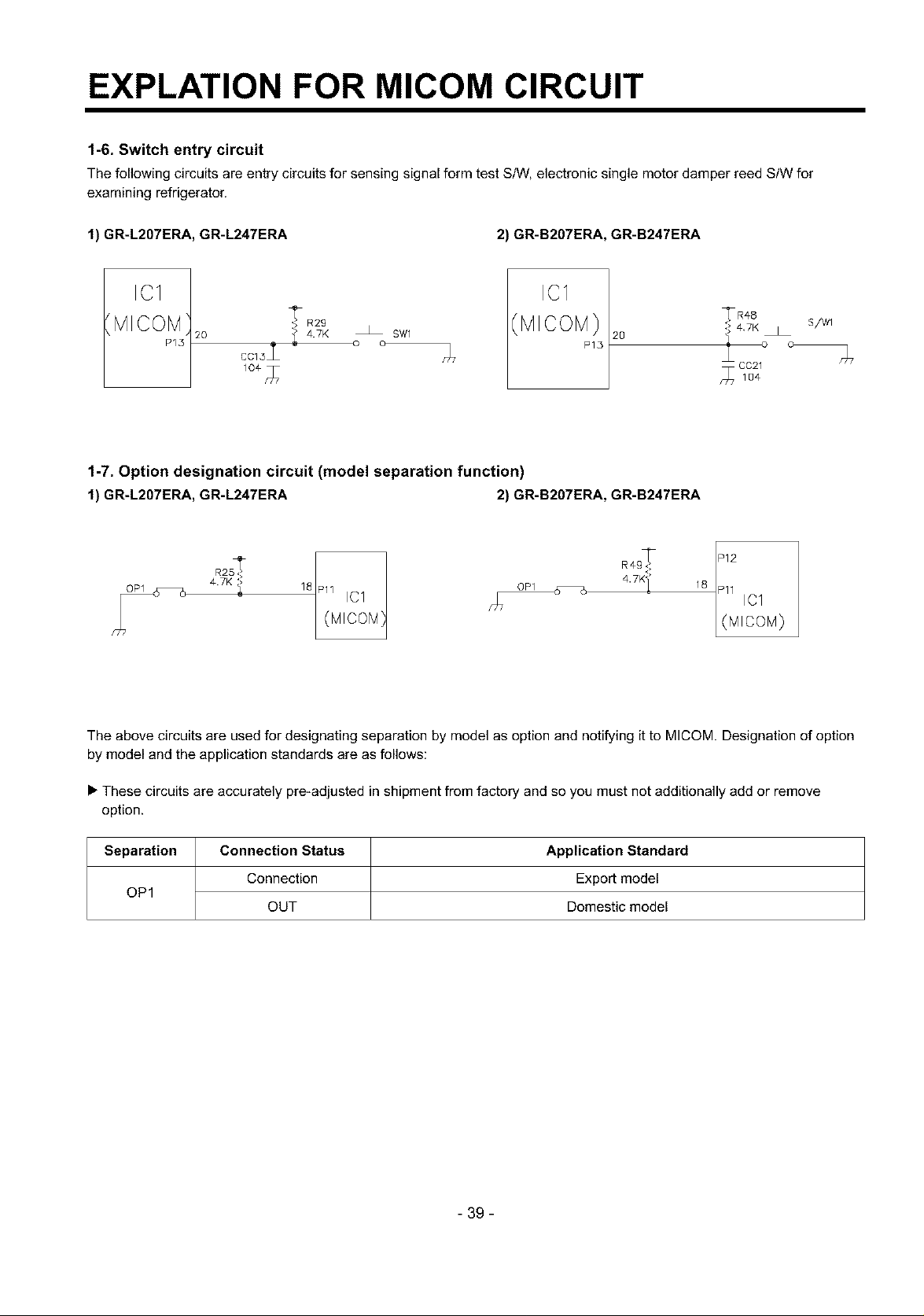
1-6. Switch entry circuit
The following circuits are entry circuits for sensing signal form test S/VV,electronic single motor damper reed StW for
examining refrigerator.
1) GR-L207ERA, GR-L247ERA 2) GR-B207ERA, GR-B247ERA
IC1
MICOM
20 _ 47K o_ o SW1
P15
1-7. Option designation circuit (model separation function)
1) GR-L207ERA, GR-L247ERA 2) GR-B207ERA, GR-B247ERA
47K 1 18
R2S'_ Pll 161
hi7 (MIOOM}
The above circuits are used for designating separation by model as option and notifying it to MICOM. Designation of option
by model and the application standards are as follows:
_R2g
cc13L _7
IC1
(MICOM}
P15
2O
112R4 18 11 IC1
L(MIcoM)
• These circuits are accurately pre-adjusted in shipment from factory and so you must not additionally add or remove
option.
Separation Connection Status Application Standard
OP1
Connection Export model
OUT Domestic model
- 39 -
EXPLATION FOR MICOM CIRCUIT
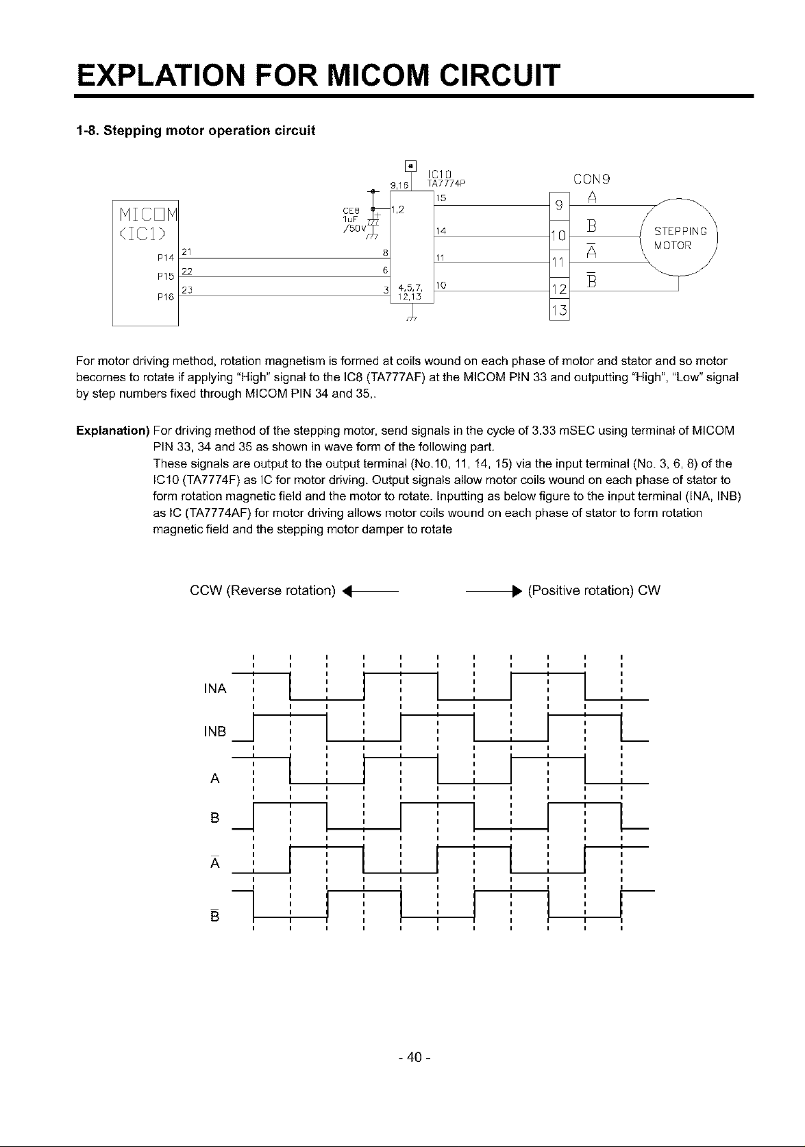
1-8. Stepping motor operation circuit
IC10 CON9
TA777#P
9,16
HIOOH
21
P14
22
P15
25
P16
For motor driving method, rotation magnetism is formed at coils wound on each phase of motor and stator and so motor
becomes to rotate if applying "High" signal to the IC8 (TA777AF) at the MICOM PIN 33 and outputting "High", "Low" signal
by step numbers fixed through MICOM PIN 34 and 35,.
Explanation) For driving method of the stepping motor, send signals in the cycle of 3.33 mSEC using terminal of MICOM
PIN 33, 34 and 35 as shown in wave form of the following part.
These signals are output to the output terminal (No.10, 11, 14, 15) via the input terminal (No. 3, 6, 8) of the
IC10 (TA7774F) as IC for motor driving. Output signals allow motor coils wound on each phase of stator to
form rotation magnetic field and the motor to rotate. Inputting as below figure to the input terminal (INA, INB)
as IC (TA7774AF) for motor driving allows motor coils wound on each phase of stator to form rotation
magnetic field and the stepping motor damper to rotate
CE8 1,2
/5ov
luF 68_
3 4,_
14 10
11 11
12 13
13
\
STEPPING
MOTOR
CCW (Reverse rotation) 4 _. (Positive rotation) CW
I I I I I I I I I I I
I I I I I I I I I I I
INA ,
I I I I I I I I I I I
INB
/ ' ' I --L'
I I I I
,-_ ,,,, } ,
A I
I I I I
I I I I
o_1
I I I
I I
I I
.._ I I
I I I
i i
I I I
I
I I I I
I
I
I ,
I I I I
"T" I
I I
' ' i
I I
I I
I I I
I I I I
I I
I I
i i
I I
-r r
I I I I
I
I
L
I
I
i-
I
- 40 -
EXPLATION FOR MICOM CIRCUIT
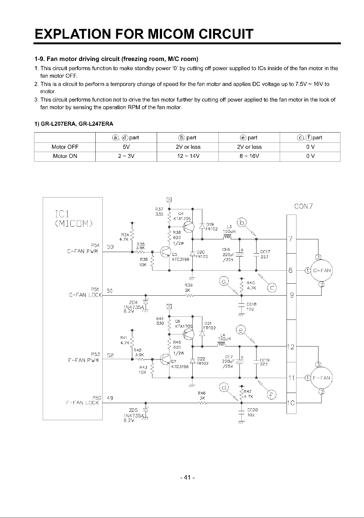
1-9. Fan motor driving circuit (freezing room, M/C room)
1. This circuit performs function to make standby power '0' by cutting off power supplied to ICs inside of the fan motor in the
fan motor OFF.
2. This is a circuit to perform a temporary change of speed for the fan motor and applies DC voltage up to 7.5V - 16V to
motor.
3. This circuit performs function not to drive the fan motor further by cutting off power applied to the fan motor in the lock of
fan motor by sensing the operation RPM of the fan motor.
1) GR-L207ERA, GR-L247ERA
(_) part (_) part (_),c_)part
Motor OFF 5V
Motor ON 2 - 3V
2V or less 2V or less 0 V
12 - 14V 8- 16V OV
CON7
C FAN PWM
C FAN LOCK
F FAN P_!M
F FAN LOCK
P54
P51
P53
PSO
53
5O
52
49
4,7K R35
R41
_42
R36 <<>
1OK _>
R¢4
350 021
R43
1OK
R#6
/,,/v,
2K
FR1D2
L_
15DuH
220uF CC19
/25V _223
\_ _#7K
CC20
7
9
11
I0
6.2V
-41 -
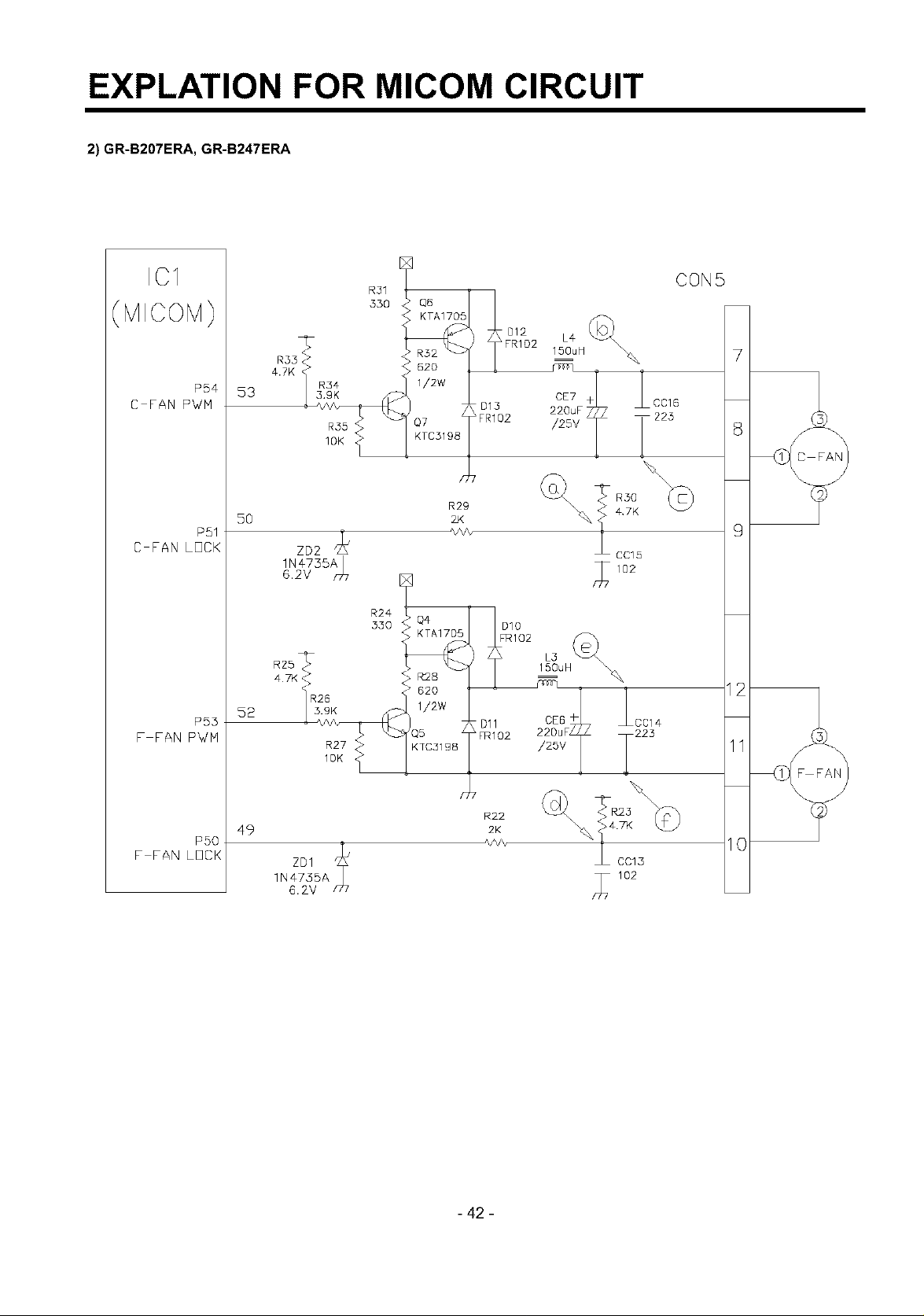
EXPLATION FOR MICOM CIRCUIT
2) GR-B207ERA, GR-B247ERA
IC1
(MICOM)
C FAN PV/M
C FAN LOCK
F FAN PWM
P54
P51
P53
53
5O
52
4.7K
zD2
1N¢735A
6.2V _r77
R55
1OK
R31
330
R24
330
R29
2JK
R:2B
62O
1/2w
85 / Dll
K7C31 g8
&FRI02
CON5
L4
150uH: 7
2_E7F * _CC16
I-
/25v T 225 8
\ 4.7K
CC15
77 02
22CDEuSF+ L2C2C14
/2sv T 11
(
9
(
F FAN LOCK
PSO
49
- 42 -
R22
2K
\
%] cc_3 10
/_7 102
EXPLATION FOR MICOM CIRCUIT
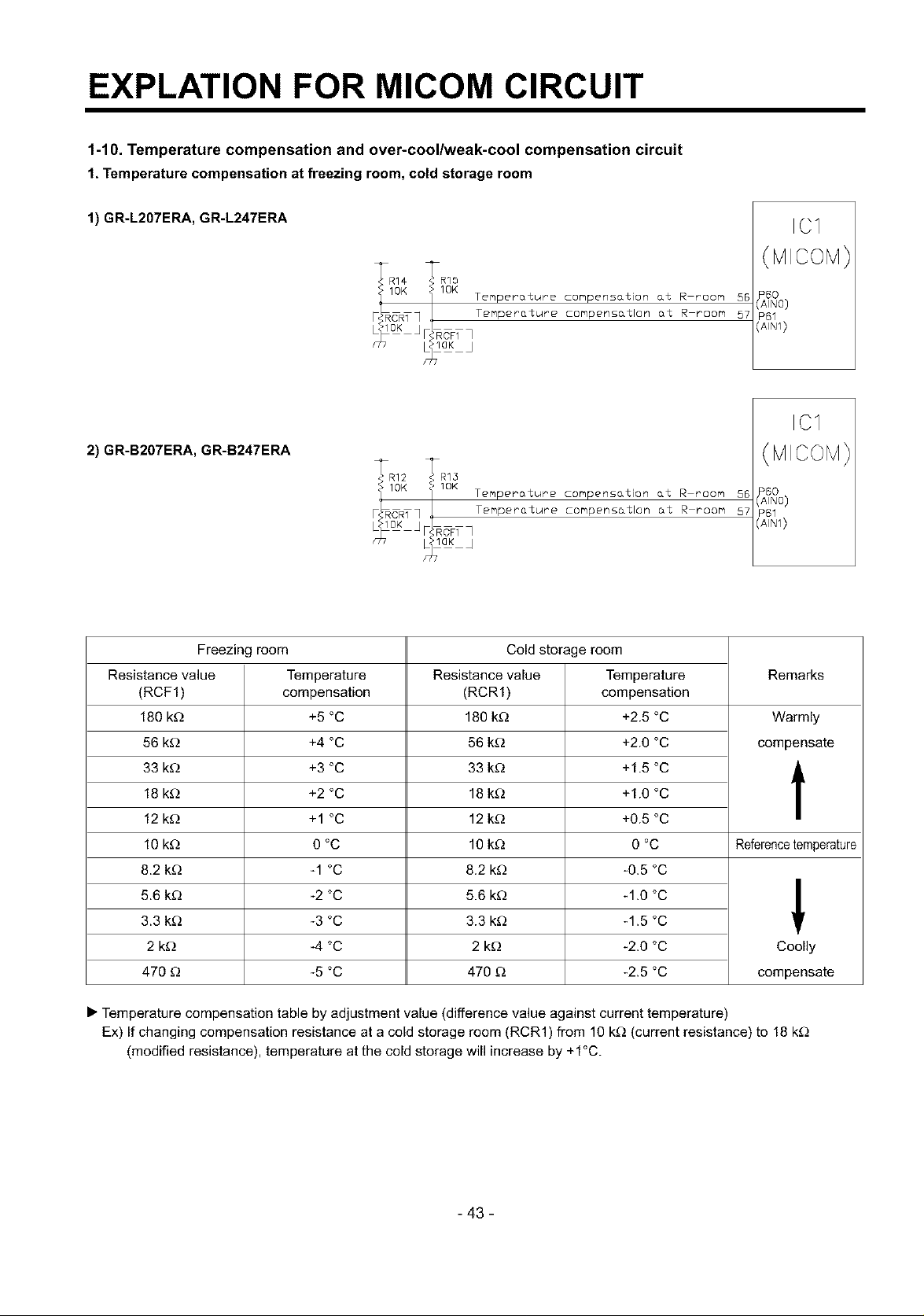
1-10. Temperature compensation and over-cool/weak-cool compensation circuit
1. Temperature compensation at freezing room,cold storage room
1) GR-L207ERA, GR-L247ERA
IRR14 _R15
OK ]'IOK Temperature compens&tion &t R moore 55
CRTq _ Temperature compens_tlon at R room 57
_laK J
2) GR-B207ERA, GR-B247ERA
_-• R12 _[ R13
'Ft_OK i IOK Temperature compensation at R room 56
CRT] Temperature compens&tlon at R room 57
Freezing room Cold storage room
Resistance value Temperature Resistance value Temperature Remarks
(RCF1) compensation (RCR1) compensation
180 k_ +5 °C 180 k_ +2.5 °C Warmly
56 k_) +4 °C 56 k_ +2.0 °C compensate
33 k_) +3 °C 33 k_ +1.5 °C
18 k£_ +2 °C 18 k£_ +1.0 °C
12 k£_ +1 °C 12 k£_ +0.5 °C
10 k_ 0 °C 10 k_ 0 °C Referencetemperature
8.2 k_ -1 °C 8.2 k_ -0.5 °C
5.6 kD -2 °C 5.6 k_ -1.0 °C
3.3 k£_ -3 °C 3.3 k_ -1.5 °C '
ICI
ICI
2 k_) -4 °C 2 k_) -2.0 °C Coolly
470 _ -5 °C 470 £_ -2.5 °C compensate
• Temperature compensation table by adjustment value (difference value against current temperature)
Ex) If changing compensation resistance at a cold storage room (RCR1) from 10 kD (current resistance) to 18 k_
(modified resistance), temperature at the cold storage will increase by +1°C.
- 43 -
EXPLATION FOR MICOM CIRCUIT
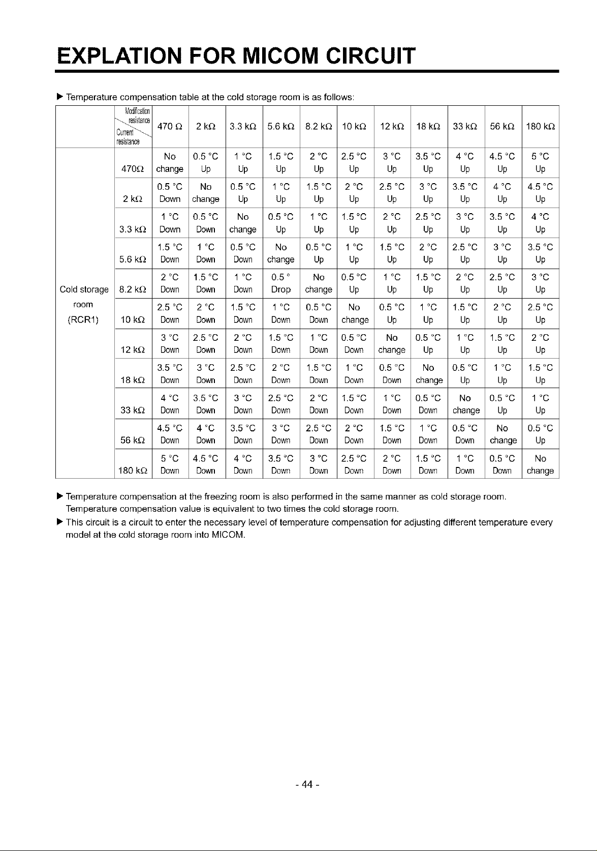
• Temperature compensation table at the cold storage room is as follows:
Mod_icaton
470£_ 2kD 3.3kD 5.6kD 8.2k£_ 10k£_ 12kD 18kD 33kD 56kD 180kD
resistance
No 0.5 °C 1 °C 1.5 °C 2 °C 2.5 °C 3 °C 3.5 °C 4 °C 4.5 °C 5 °C
470D change Up Up Up Up Up Up Up Up Up Up
0.5 °C No 0.5 °C 1 °C 1.5 °C 2 °C 2.5 °C 3 °C 3.5 °C 4 °C 4.5 °C
2 kD Down change Up Up Up Up Up Up Up Up Up
1 °C 0.5 °C No 0.5 °C 1 °C 1.5 °C 2 °C 2.5 °C 3 °C 3.5 °C 4 °C
3.3 k_) Down Down change Up Up Up Up Up Up Up Up
1.5 °C 1 °C 0.5 °C No 0.5 °C 1 °C 1.5 °C 2 °C 2.5 °C 3 °C 3.5 °C
5.6 k_) Down Down Down change Up Up Up Up Up Up Up
2 °C 1.5 °C 1 °C 0.5 ° No 0.5 °C 1 °C 1.5 °C 2 °C 2.5 °C 3 °C
Cold storage
room
(RCR1)
8.2 k_) Down Down Down Drop change Up Up Up Up Up Up
2.5 °C 2 °C 1.5 °C 1 °C 0.5 °C No 0.5 °C 1 °C 1.5 °C 2 °C 2.5 °C
10 kD Down Down Down Down Down change Up Up Up Up Up
3 °C 2.5 °C 2 °C 1.5 °C 1 °C 0.5 °C No 0.5 °C 1 °C 1.5 °C 2 °C
12 kD Down Down Down Down Down Down change Up Up Up Up
3.5 °C 3 °C 2.5 °C 2 °C 1.5 °C 1 °C 0.5 °C No 0.5 °C 1 °C 1.5 °C
18 kD Down Down Down Down Down Down Down change Up Up Up
4 °C 3.5 °C 3 °C 2.5 °C 2 °C 1.5 °C 1 °C 0.5 °C No 0.5 °C 1 °C
33 kD Down Down Down Down Down Down Down Down change Up Up
4.5 °C 4 °C 3.5 °C 3 °C 2.5 °C 2 °C 1.5 °C 1 °C 0.5 °C No 0.5 °C
56 kD Down Down Down Down Down Down Down Down Down change Up
5 °C 4.5 °C 4 °C 3.5 °C 3 °C 2.5 °C 2 °C 1.5 °C 1 °C 0.5 °C No
180 kD Down Down Down Down Down Down Down Down Down Down change
• Temperature compensation at the freezing room is also performed in the same manner as cold storage room.
Temperature compensation value is equivalent to two times the cold storage room,
• This circuit is a circuit to enter the necessary level of temperature compensation for adjusting different temperature every
model at the cold storage room into MICOM.
- 44 -
 Loading...