

Page 1

CAUTION
PLEASE READ CAREFULLY THE SAFETY PRECAUTIONS OF THIS MANUAL
BEFORE CHECKING OR OPERATING THE REFRIGERATOR.
REFRIGERATOR
SERVICE MANUAL
LRSC26944SW, LRSC26944TT
LRSC26930SW, LRSC26930TT
LRSC26922SW, LRSC26922TT
LRSC26920SW, LRSC26920TT
LRSC26911SW, LRSC26911TT
LRSC26910SW, LRSC26910TT
LRSC26980SB, LRSC26980TT
http://biz.lgservice.com
Page 2

CONTENTS
WARNINGS AND PRECAUTIONS FOR SAFETY ................................................................................................................ 3
SPECIFICATIONS................................................................................................................................................................... 4
PARTS IDENTIFICATION ....................................................................................................................................................... 9
HOW TO INSTALL THE REFRIGERATOR .......................................................................................................................... 14
HOW TO ADJUST DOOR HEIGHT.................................................................................................................................... 14
FILTER ............................................................................................................................................................................... 15
HOW TO CONTROL THE ICEMAKER WATER SUPPLY.................................................................................................. 16
MICOM FUNCTION .............................................................................................................................................................. 18
EXPLANATION OF MICOM CIRCUIT.................................................................................................................................. 32
EXPLANATION OF PWB CIRCUIT .....................................................................................................................................32
PWB PARTS DIAGRAM AND LIST .....................................................................................................................................47
PWB CIRCUIT DIAGRAM ...................................................................................................................................................54
OPERATION PRINCIPLE AND REPAIR METHOD OF ICEMAKER ................................................................................... 56
OPERATION PRINCIPLE ................................................................................................................................................... 56
CONTROL METHOD ACCORDING TO FUNCTIONS....................................................................................................... 57
DEFECT DIAGNOSIS FUNCTION..................................................................................................................................... 59
CIRCUIT................................................................................................................................................................................ 60
TROUBLE DIAGNOSIS........................................................................................................................................................ 63
TROUBLESHOOTING ....................................................................................................................................................... 63
FAULTS .............................................................................................................................................................................. 73
COOLING CYCLE HEAVY REPAIR ................................................................................................................................... 90
HOW TO DEAL WITH CLAIMS.......................................................................................................................................... 97
HOW TO DISASSEMBLE AND ASSEMBLE..................................................................................................................... 103
DOOR............................................................................................................................................................................... 103
HANDLE ........................................................................................................................................................................... 104
FAN SHROUD GRILLE .................................................................................................................................................... 105
ICEMAKER ASSEMBLY................................................................................................................................................... 105
DISPENSER..................................................................................................................................................................... 106
TV-RADIO ............................................................................................................................................................................107
EXPLODED VIEW............................................................................................................................................................... 113
REPLACEMENT PARTS LIST ........................................................................................................................................... 131
- 2 -
Page 3

WARNINGS AND PRECAUTIONS FOR SAFETY
Please observe the following safety precautions to use the
refrigerator safely and correctly and to prevent accident or
injury when servicing.
1. Be careful of an electric shock. Disconnect power cord
from wall outlet and wait for more than three minutes
before replacing PWB parts. Disconnect the power
whenever replacing and repairing electric components.
2. If disconnecting the power, wait at least 5 minutes
before plugging the unit back in.
3. Before touching the power cord, make sure the cord is
not damaged. If the power cord is damaged, it can
cause a fire or an electrical shock.
4. Make sure the unit has a dedicated circuit breaker.
Overloading the circuit can cause a fire.
5. Please make sure the outlet is properly grounded.
Particularly in a wet or damp area.
6. Use standard electrical components.
7. Remove dust and foreign materials from the housing
and connecting parts.
8. Do not fray, damage, run over, kink, bend, pull out, or
twist the power cord.
9. Please check for evidence of moisture intrusion in the
electrical components. Replace the parts or mask with
insulation tape if moisture intrusion is confirmed.
10. Stay clear of the icemaker with hands or tools if the unit
has power. Do not try to manually turn the ice maker
even when turned off.
11. Customers should not repair the refrigerator
themselves. This work requires special tools and
knowledge. Non-professionals could cause fire, injury,
or damage to the product.
12. Do not store flammable materials such as ether,
benzene, alcohol, chemicals, or gas in the refrigerator.
13. Do not put anything on top of the refrigerator,
especially something containing water, like a vase.
14. Do not put glass bottles of water into the freezer. The
contents will freeze and break the bottles.
15. If you scrap or discard the refrigerator, remove the
doors and dispose of it where children are not likely to
play in or around it.
- 3 -
Page 4

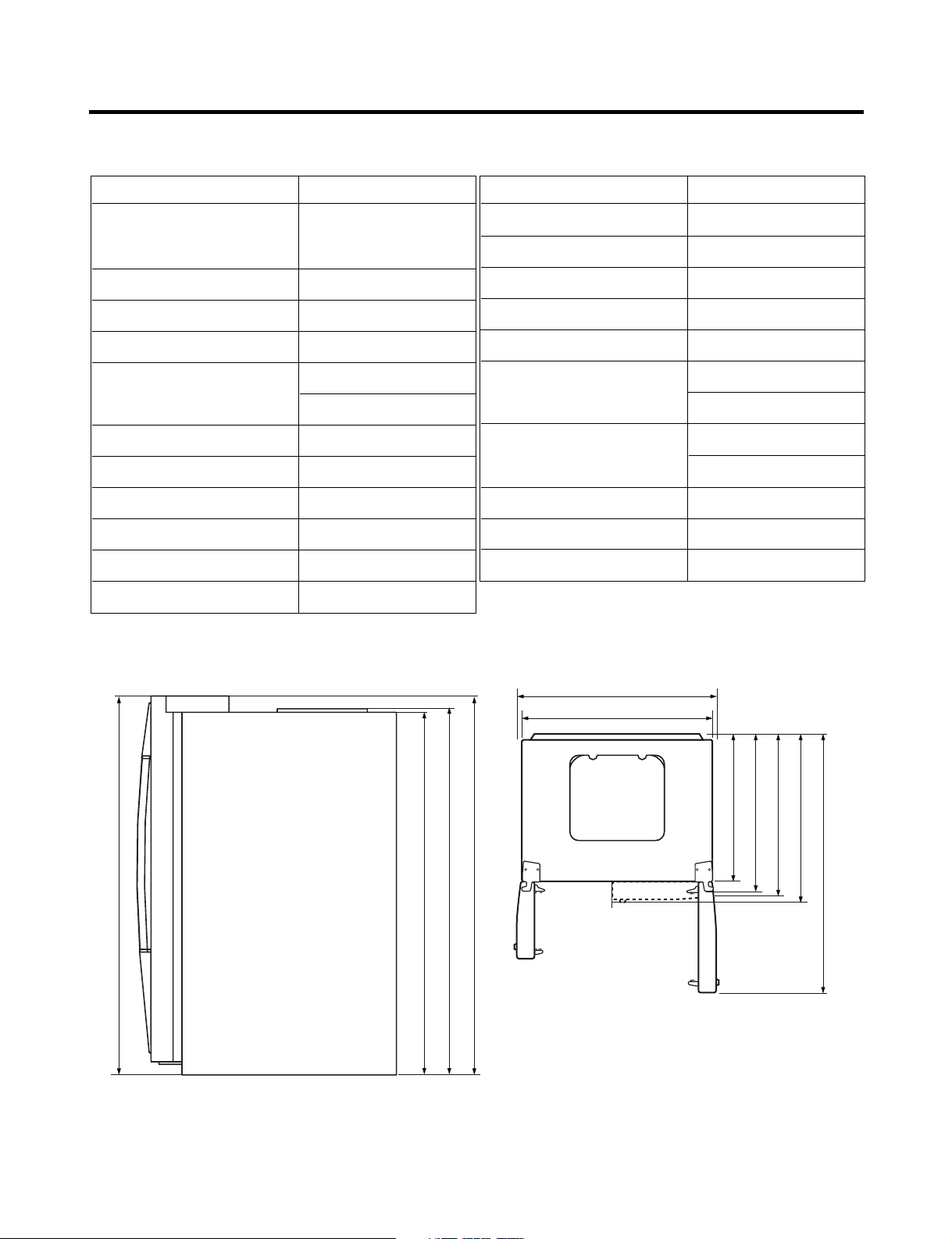
SPECIFICATIONS
Ref No. : LRSC26944**
ITEMS SPECIFICATIONS
DIMENSIONS 908 X 896 X 1771 mm
11
5
W
X
D X H (35
/16
X
35
/16
11
/16
X
69
in.)
NET WEIGHT 149 kg (328.5 lbs.)
COOLING SYSTEM Fan Cooling
TEMPERATURE CONTROL Micom Control
DEFROSTING SYSTEM Full Automatic
Heater Defrost
INSULATION Cyclo-Pentane
COMPRESSOR PTC Starting Type
EVAPORATOR Fin Tube Type
CONDENSER Wire Condenser
REFRIGERANT R134a (185g) (6
1
/2 oz.)
LUBRICATING OIL FREOL @10G (320 cc)
ITEMS SPECIFICATIONS
DRIER MOLECULAR SIEVE XH-7
CAPILLARY TUBE ID Ø0.83
FIRST DEFROST 4 - 5 Hours
DEFROST CYCLE 13 - 15 Hours
DEFROSTING DEVICE Heater, Sheath
ANTI-SWEAT HEATER Dispenser Duct Door Heater
Dispenser Heater
ANTI-FREEZING HEATER Water Tank Heater
Damper Heater
FREEZER LAMP 40W (2 EA)
REFRIGERATOR LAMP 40W (4 EA)
DISPENSER LAMP 15W (1 EA)
in.)
16
/
11
1771 mm (69
1004 mm (391/2 in.)
3
908 mm (35
in.)
in.)
2
/
1
1741.5 mm (68
Front View Top View
in.)
4
/
16
3
/
11
1771 mm (69
1746.5 mm (68
/4 in.)
in.)
in.)
in.)
2
8
8
/
/
1
/
5
5
724 mm (28
779 mm (30
829 mm (32
in.)
in.)
8
/
16
5
/
5
897 mm (35
1261 mm (49
- 4 -
Page 5
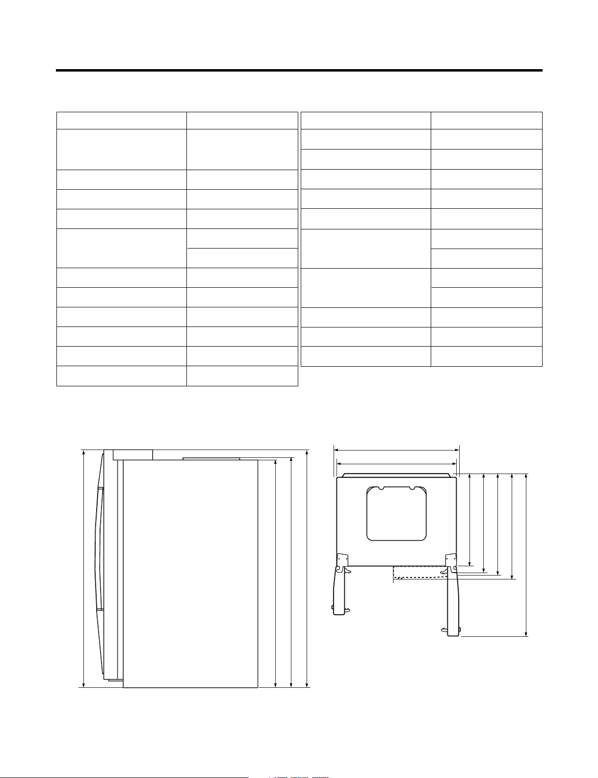
SPECIFICATIONS
724 mm (28
1
/
2
in.)
1004 mm (391/2 in.)
908 mm (35
3
/4 in.)
779 mm (30
5
/
8
in.)
829 mm (32
5
/
8
in.)
897 mm (35
5
/
16
in.)
1261 mm (49
5
/
8
in.)
1741.5 mm (68
1
/
2
in.)
1746.5 mm (68
3
/
4
in.)
1771 mm (69
11
/
16
in.)
1771 mm (69
11
/
16
in.)
Ref No. : LRSC26930**
ITEMS SPECIFICATIONS
DIMENSIONS 908 X 896 X 1771 mm
W
X D X
H (35
NET WEIGHT 149 kg (328.5 lbs.)
COOLING SYSTEM Fan Cooling
TEMPERATURE CONTROL Micom Control
DEFROSTING SYSTEM Full Automatic
INSULATION Cyclo-Pentane
COMPRESSOR PTC Starting Type
EVAPORATOR Fin Tube Type
CONDENSER Wire Condenser
REFRIGERANT R134a (185g) (6
LUBRICATING OIL FREOL @10G (320 cc)
11
/16X355/16X6911/16 in.)
Heater Defrost
1
/2 oz.)
ITEMS SPECIFICATIONS
DRIER MOLECULAR SIEVE XH-7
CAPILLARY TUBE ID Ø0.83
FIRST DEFROST 4 - 5 Hours
DEFROST CYCLE 13 - 15 Hours
DEFROSTING DEVICE Heater, Sheath
ANTI-SWEAT HEATER Dispenser Duct Door Heater
Dispenser Heater
ANTI-FREEZING HEATER Water Tank Heater
Damper Heater
FREEZER LAMP 40W (1 EA)
REFRIGERATOR LAMP 40W (4 EA)
DISPENSER LAMP 15W (1 EA)
Front View Top View
- 5 -
Page 6

SPECIFICATIONS
Ref No. : LRSC26920**, LRSC26922**
ITEMS SPECIFICATIONS
DIMENSIONS 908 X 896 X 1771 mm
W
X D X
H (35
NET WEIGHT 149 kg (328.5 lbs.)
COOLING SYSTEM Fan Cooling
TEMPERATURE CONTROL Micom Control
DEFROSTING SYSTEM Full Automatic
INSULATION Cyclo-Pentane
COMPRESSOR PTC Starting Type
EVAPORATOR Fin Tube Type
CONDENSER Wire Condenser
REFRIGERANT R134a (185g) (6
LUBRICATING OIL FREOL @10G (320 cc)
11
/16X355/16X6911/16 in.)
Heater Defrost
1
/2 oz.)
ITEMS SPECIFICATIONS
DRIER MOLECULAR SIEVE XH-7
CAPILLARY TUBE ID Ø0.83
FIRST DEFROST 4 - 5 Hours
DEFROST CYCLE 13 - 15 Hours
DEFROSTING DEVICE Heater, Sheath
ANTI-SWEAT HEATER Dispenser Duct Door Heater
Dispenser Heater
ANTI-FREEZING HEATER Water Tank Heater
Damper Heater
FREEZER LAMP 40W (1 EA)
REFRIGERATOR LAMP 40W (4 EA)
DISPENSER LAMP 15W (1 EA)
in.)
16
/
11
1771 mm (69
1004 mm (391/2 in.)
3
908 mm (35
in.)
in.)
2
/
1
1741.5 mm (68
Front View Top View
in.)
4
/
16
3
/
11
1771 mm (69
1746.5 mm (68
/4 in.)
in.)
in.)
in.)
2
8
8
/
/
1
/
5
5
724 mm (28
779 mm (30
829 mm (32
in.)
in.)
8
/
16
5
/
5
897 mm (35
1261 mm (49
- 6 -
Page 7

SPECIFICATIONS
Ref No. : LRSC26910**, LRSC26911**
ITEMS SPECIFICATIONS
DIMENSIONS 908 X 896 X 1771 mm
11
5
W
X
D X H (35
/16
X
35
/16
11
/16
X
69
in.)
NET WEIGHT 149 kg (328.5 lbs.)
COOLING SYSTEM Fan Cooling
TEMPERATURE CONTROL Micom Control
DEFROSTING SYSTEM Full Automatic
Heater Defrost
INSULATION Cyclo-Pentane
COMPRESSOR PTC Starting Type
EVAPORATOR Fin Tube Type
CONDENSER Wire Condenser
REFRIGERANT R134a (185g) (6
1
/2 oz.)
LUBRICATING OIL FREOL @10G (320 cc)
ITEMS SPECIFICATIONS
DRIER MOLECULAR SIEVE XH-7
CAPILLARY TUBE ID Ø0.83
FIRST DEFROST 4 - 5 Hours
DEFROST CYCLE 13 - 15 Hours
DEFROSTING DEVICE Heater, Sheath
ANTI-SWEAT HEATER Dispenser Duct Door Heater
Dispenser Heater
ANTI-FREEZING HEATER Water Tank Heater
Damper Heater
FREEZER LAMP 40W (1 EA)
REFRIGERATOR LAMP 40W (3 EA)
DISPENSER LAMP 15W (1 EA)
in.)
16
/
11
1771 mm (69
1004 mm (391/2 in.)
3
908 mm (35
in.)
in.)
2
/
1
1741.5 mm (68
Front View Top View
in.)
4
/
16
3
/
11
1771 mm (69
1746.5 mm (68
/4 in.)
in.)
in.)
in.)
2
8
8
/
/
1
/
5
5
724 mm (28
779 mm (30
829 mm (32
in.)
in.)
8
8
/
/
5
1
892 mm (35
1261 mm (49
- 7 -
Page 8
SPECIFICATIONS
Ref No. : LRSC26980TT
ITEMS SPECIFICATIONS
DIMENSIONS 908 X 896 X 1771 mm
11
5
W
X
D X H (35
/16
X
35
/16
11
/16
X
69
in.)
NET WEIGHT 154 kg (339.5 lbs.)
COOLING SYSTEM Fan Cooling
TEMPERATURE CONTROL Micom Control
DEFROSTING SYSTEM Full Automatic
Heater Defrost
INSULATION Cyclo-Pentane
COMPRESSOR PTC Starting Type
EVAPORATOR Fin Tube Type
CONDENSER Wire Condenser
REFRIGERANT R134a (185g) (6
1
/2 oz.)
LUBRICATING OIL FREOL @10G (320 cc)
ITEMS SPECIFICATIONS
DRIER MOLECULAR SIEVE XH-7
CAPILLARY TUBE ID Ø0.83
FIRST DEFROST 4 - 5 Hours
DEFROST CYCLE 13 - 15 Hours
DEFROSTING DEVICE Heater, Sheath
ANTI-SWEAT HEATER Dispenser Duct Door Heater
Dispenser Heater
ANTI-FREEZING HEATER Water Tank Heater
Damper Heater
FREEZER LAMP 40W (2 EA)
REFRIGERATOR LAMP 40W (4 EA)
DISPENSER LAMP 15W (1 EA)
in.)
16
/
11
1771 mm (69
1004 mm (391/2 in.)
3
908 mm (35
in.)
in.)
2
/
1
1741.5 mm (68
Front View Top View
in.)
4
/
16
3
/
11
1771 mm (69
1746.5 mm (68
/4 in.)
in.)
in.)
in.)
2
8
8
/
/
1
/
5
5
724 mm (28
779 mm (30
829 mm (32
in.)
in.)
8
/
16
5
/
5
897 mm (35
1261 mm (49
- 8 -
Page 9

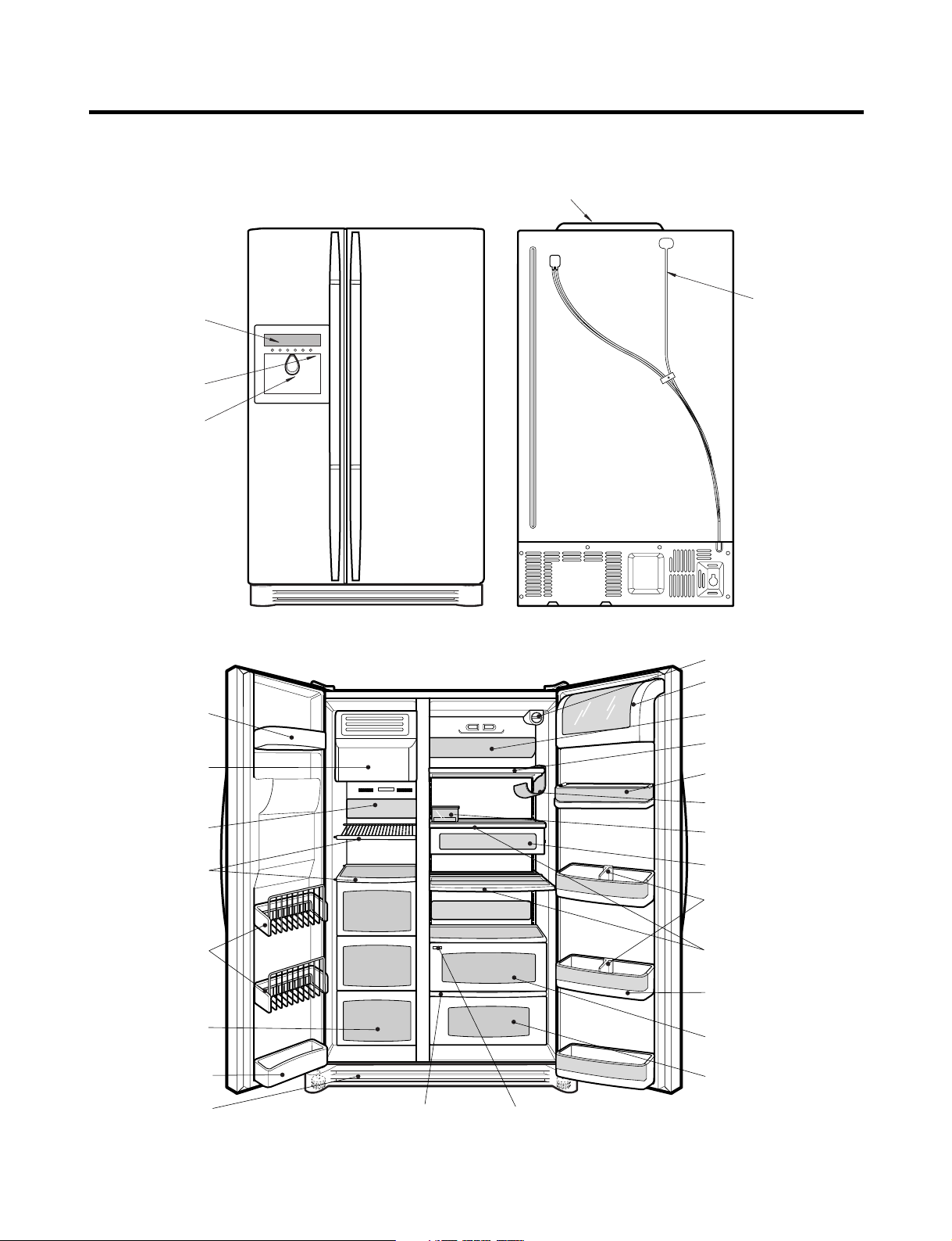
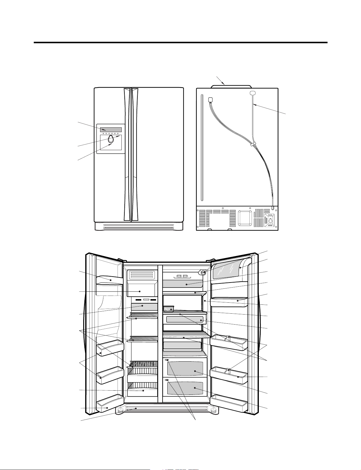
PARTS IDENTIFICATION
Humidity SwitchOptiChill Display
Lamp
Shelf
Egg Box
Snack Drawer
Vegetable Drawer
OptiChill
Door Rack
Shelf
Grab and Go
Can Server
Lamp
Lower Cover
Dairy Products Corner
Water Filter
Door Rack
Drawer
(Wire/Plastic)
Freezer
Compartment
Refrigerator
Compartment
Automatic
Icemaker
Door Rack
Shelf
Door Rack
Bottle Guide
Display Panel
Dispenser Lamp
Ice & Water
Dispenser Button
PCB Cover
Water Tubes
Ref No. : LRSC26944**
- 9 -
Page 10
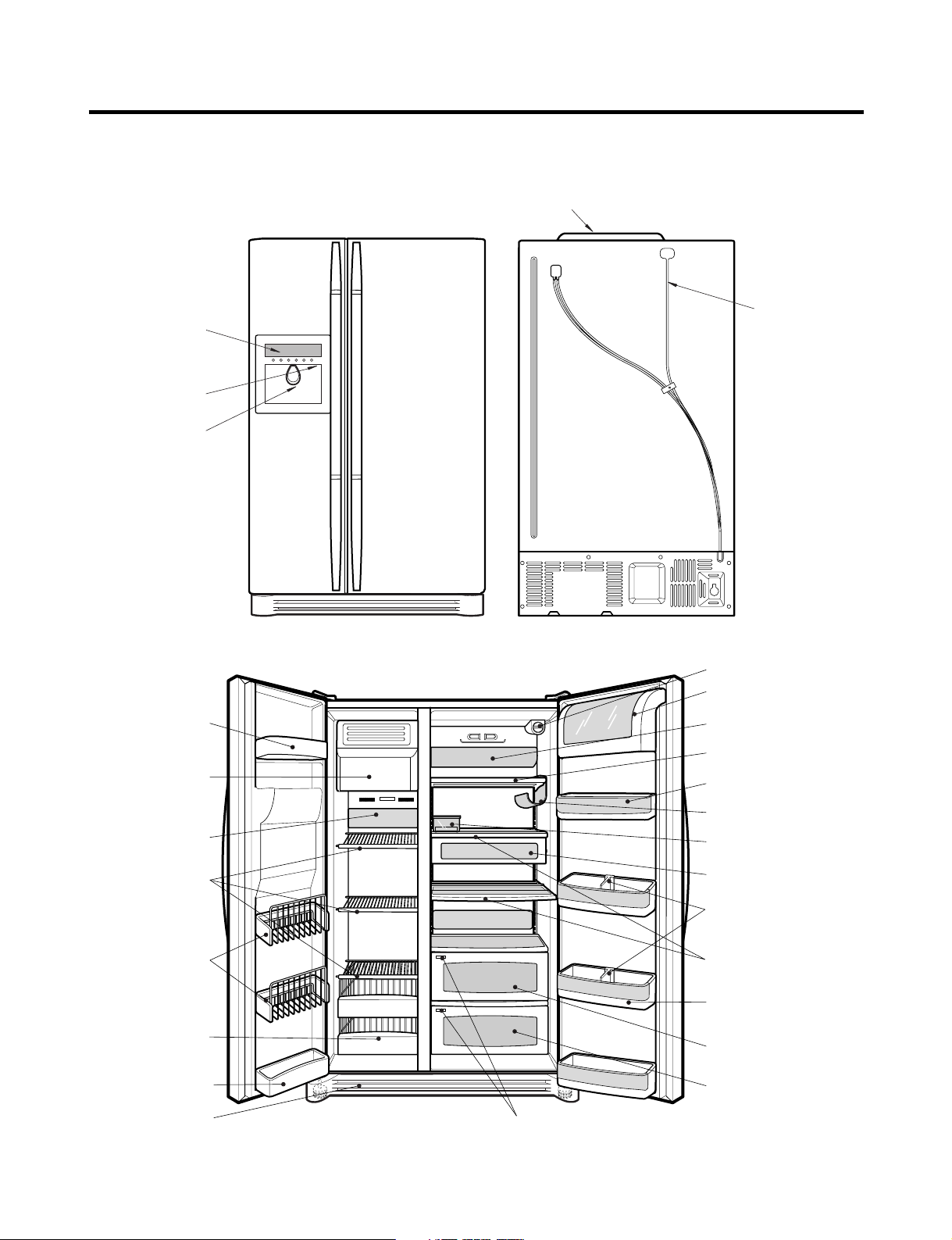
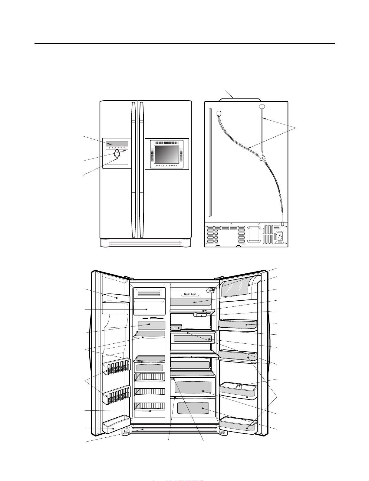
PARTS IDENTIFICATION
Humidity Switch
Lamp
Shelf
Egg Box
Snack Drawer
Vegetable Drawer
OptiChill
Door Rack
Shelf
Grab and Go
Wine Holder
Lamp
Lower Cover
Dairy Products Corner
Door Rack
Drawer
(Wire/Plastic)
Freezer
Compartment
Refrigerator
Compartment
Automatic
Icemaker
Door Rack
Shelf
Bottle Guide
Display Panel
Dispenser Lamp
Ice & Water
Dispenser Button
OptiChill Display
Door Rack
Water Filter
PCB Cover
Water Tubes
Ref No. : LRSC26930**
- 10 -
Page 11
PARTS IDENTIFICATION
Humidity Switch
Lamp
Shelf
Egg Box
Snack Drawer
Vegetable Drawer
Vegetable Drawer
/Meat Drawer
Door Rack
Shelf
Door Rack
Wine Holder
Lamp
Lower Cover
Dairy Products Corner
Door Rack
Drawer
(Wire/Plastic)
Freezer
Compartment
Refrigerator
Compartment
Automatic
Icemaker
Door Rack
Shelf
Bottle Guide
Display Panel
Dispenser Lamp
Ice & Water
Dispenser Button
PCB Cover
Water Tubes
Door Rack
Water Filter
Ref No. : LRSC26920**, LRSC26922**
- 11 -
Page 12
PARTS IDENTIFICATION
Lamp
Shelf
Egg Box
Snack Drawer
Vegetable Drawer
Vegetable Drawer
/Meat Drawer
Door Rack
Shelf
Door Rack
Wine Holder
Lamp
Lower Cover
Dairy Products Corner
Door Rack
Drawer
(Wire/Plastic)
Freezer
Compartment
Refrigerator
Compartment
Automatic
Icemaker
Door Rack
Shelf
PCB Cover
Water Tubes
Door Rack
Water Filter
Humidity Switch
Bottle Guide
Display Panel
Dispenser Lamp
Ice & Water
Dispenser Button
Ref No. : LRSC26910**, LRSC26911**
- 12 -
Page 13
PARTS IDENTIFICATION
Humidity SwitchOptiChill Display
Lamp
Shelf
Egg Box
Snack Drawer
Vegetable Drawer
OptiChill
Door Rack
Shelf
Grab and Go
Can Server
Lamp
Lower Cover
Dairy Products Corner
Water Filter
Door Rack
Drawer
(Wire/Plastic)
Freezer
Compartment
Refrigerator
Compartment
Automatic
Icemaker
Door Rack
Shelf
Door Rack
Bottle Guide
Display Panel
Dispenser Lamp
Ice & Water
Dispenser Button
PCB Cover
Water Tubes
Ref No. : LRSC26980TT
- 13 -
Page 14
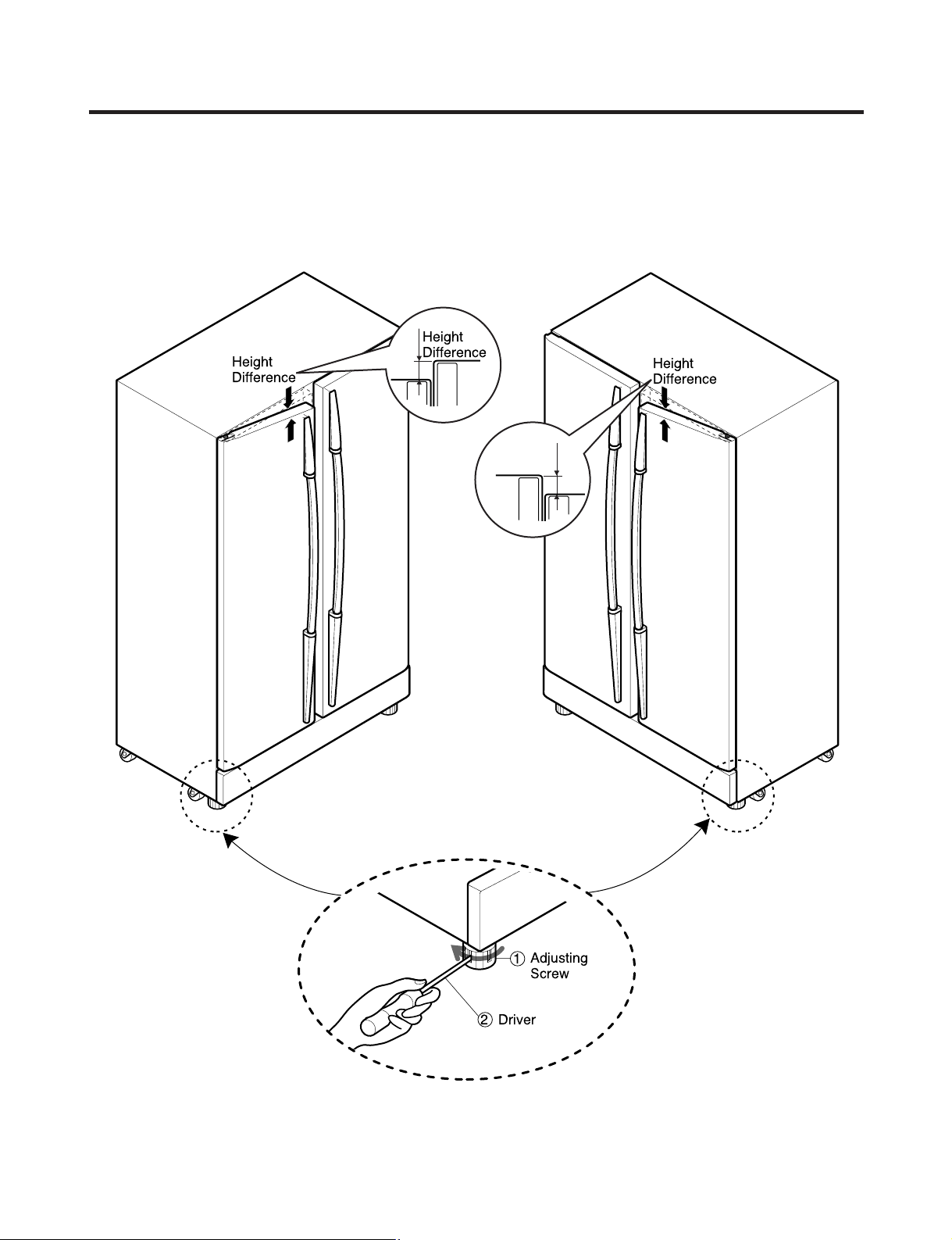
HOW TO INSTALL REFRIGERATOR
Adjusting
Screw
Driver
Height
Difference
Height
Difference
Height
Difference
Height
Difference
1
2
How to Adjust Door Height of Refrigerator
■ Level the refrigerator first. (If the refrigerator is not installed on a flat floor, the height of freezer and refrigerator doors
may not be the same.)
If the freezer door is lower than the refrigerator door: If the freezer door is higher than the refrigerator door:
Insert a driver into the groove of the adjusting
screw and turn in the direction of the arrow (clockwise)
until the refrigerator is level.
- 14 -
Insert a driver into the groove of the adjusting
screw and turn in the direction of the arrow (clockwise)
until the refrigerator is level.
Page 15
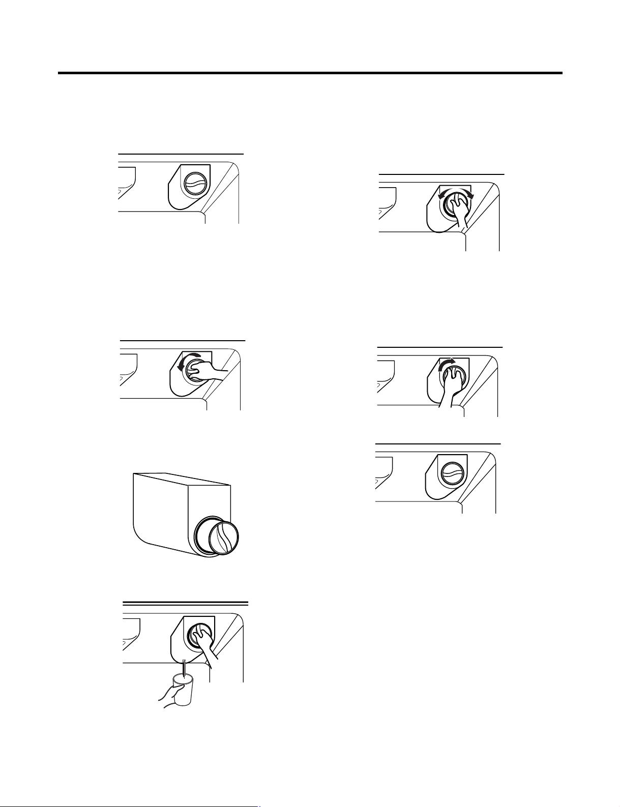
HOW TO INSTALL REFRIGERATOR
Filter
Replace the filter when the indicator light comes on or the
performance of the icemaker or water dispenser decreases
noticeably.
After changing the water filter cartridge, reset the water
filter status display and indicator light by pressing and
holding the BUTTON for 3 seconds.(page 18)
1. Remove the old cartridge.
Twist the knob of the cartridge counter clockwise.
2. Replace with a new cartridge.
Take the new cartridge out of its packaging and remove the
protective cover from the o-rings.
With the cartridge knob in the vertical position, push the
new filter cartridge into the cover until it stops.
If you can’t turn the filter from side to side, it isn’t fully
inserted. Push it in firmly and twist it into place. You will
hear the snap when it clicks into place.
Using the handle, twist the cartridge clockwise about 1/4
turn.
When the cartridge is removed, you will feel it click .
Pull out the cartridge.
NOTE: There will be some water(25cc) in the filter
cartridge. Some spilling may occur. Catch it in a
bowl or towel.
3. After replacing filter, dispense water through the water
dispenser for 3 minutes to purge the system.
There may be a little air in the line, causing noise or
hissing. Run the water at the dispenser until the hissing
stops.
NOTE: - To purchase replacement water filter cartridges,
visit your local appliance dealer or part distributor,
or call 1-877-714-7486.
- You can also visit our website :
www.lgappliances.com
- 15 -
Page 16
HOW TO INSTALL REFRIGERATOR
2
1
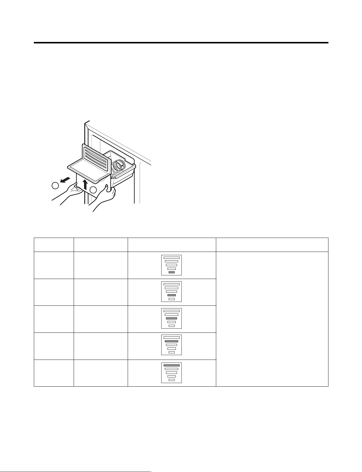
Ice Maker
1) How to Control the Amount of Water Supplied to Icemaker.
Caution : • Do not put hands or tools into the chute to confirm the operation of geared motor.
It may damage the refrigerator or hurt your hands.
To gain access to the ice maker, remove the ice bin in the upper part of the freezer compartment. Then use the water
control switch to change the amount of water supplied to the ice maker.
Water supply amount TABLE
STAGE TIME TO SUPPLY INDICATIONS REMARKS
1
2
3
4
5
4 sec.
4.5 sec.
5 sec.
5.5 sec.
6 sec.
The water amount will vary depending
on the Water Control Switch setting as
well as the water pressure of the
connected water line.
- 16 -
Page 17
HOW TO INSTALL REFRIGERATOR
ww
WARNING
Personal Injury Hazard
Avoid contact with the moving parts of the ejector
mechanism or with the heating element that releases
the cubes. DO NOT place fingers or hands on the
automatic icemaking mechanism while the refrigerator
is plugged in.
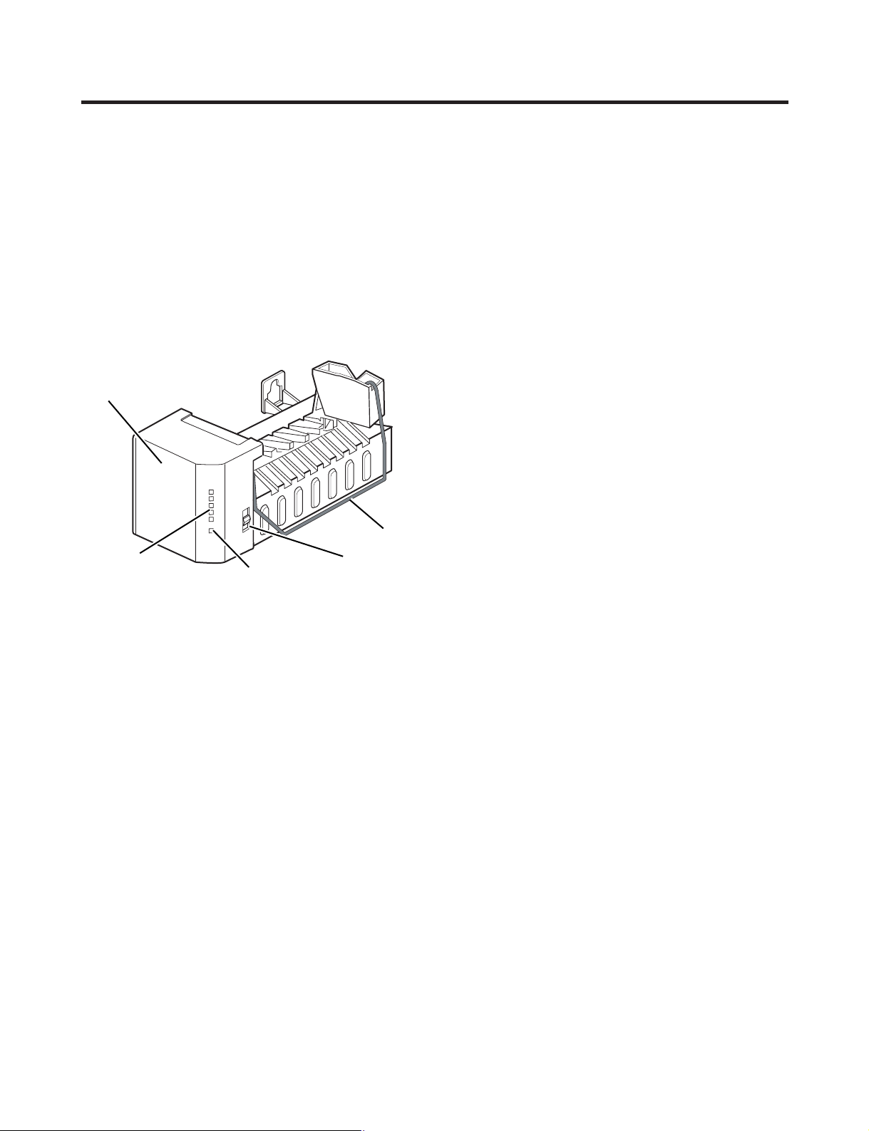
2) Operating instructions
A newly-installed refrigerator may take up to 24 hours
to begin making ice.
Icemaker
Feeler Arm
Cube Size
Indicator Light
The icemaker will produce eight cubes per
cycle—approximately 120–150 cubes in a 24-hour period,
depending on freezer compartment temperature, room
temperature, number of door openings and other operating
conditions.
If the refrigerator is used before the water connection is
made to the icemaker, set the power switch to O (off).
When the refrigerator has been connected to the water
supply, set the power switch to I (on).
The icemaker will fill with water when it cools to freezing. A
newly-installed refrigerator may take up to 24 hours to
begin making ice cubes.
Throw away the first few batches of ice to allow the water
line to clear.
Be sure nothing interferes with the sweep of the feeler arm.
When the bin fills to the level of the feeler arm, the
icemaker will stop producing ice.
It is normal for several cubes to be stuck together.
If ice is not used frequently, old ice cubes will become
cloudy, taste stale, and shrink.
Water Supply
Control Switch
Power Switch
NOTE: If the cube size is smaller or larger than you
expected, you can regulate the size with the cube size
button. (normally caused by variations in water pressure.)
Every time you press the cube size button, the indicator
light goes up. The higher the position indicated, the larger
the cubes will be. (1st step is the next after the 5th step.)
3) When you should set the icemaker power
switch to O (off)
• When the water supply will be shut off for several hours.
• When the ice storage bin is removed for more than a
minute or two.
• When the refrigerator will not be used for several days.
4) Normal sounds you may hear
• The icemaker water valve will buzz as the icemaker fills
with water. If the power switch is in the I (on) position, it
will buzz even if it has not yet been hooked up to water.
To stop the buzzing, move the power switch to O (off).
NOTE: Keeping the power switch in the I (on) position
before the water line is connected can damage the
icemaker.
• You will hear the sound of cubes dropping into the bin
and water running in the pipes as the icemaker refills.
5) Preparing for Vacation
Set the icemaker power switch to O (off) and shut off the
water supply to the refrigerator.
If the ambient temperature will drop below freezing, have a
qualified servicer drain the water supply system (on some
models) to prevent serious property damage due to
flooding from ruptured water lines or connections.
- 17 -
Page 18
MICOM FUNCTION
ICEBEAM
COOLING
OFF
CUBE
FILTER
MONTH
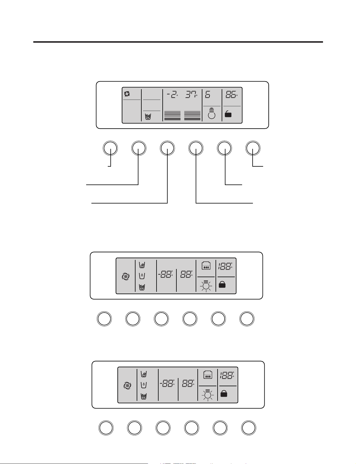
EXPRESS/JET FRZ DISPENSER FREEZER REFRIGERATOR FILTER/LIGHT LOOK
ROOM TEMP
DISPENSER & KEY
F
WATER
5
4
3
2
1
CRUSH
F F
3 SECS
Dispenser selection
button
Express Freezer/Jet Freezer
function selection button
Dispenser and Button
Lock button
Filter Timer Reset & Dispenser
Light Toggle
Refrigerator Compartment
Temperature Setting
Freezer Compartment
Temperature Setting
EXPRESS
DIGITAL CONTROL
FRZ TEMP REF TEMP
JET
CUBE
FILTER RESET
HOLD 3SECS
EXPRESS/JET FRZ DISPENSER FREEZER
REFRIGERATOR
FILTER RESET/LIGHT
LOOK
ROOM TEMP
LOCK
DISPENSER & KEY
WATER
CRUSH
3 SECS
F
C
F
C
F
C
FILTER
ON
DIGITAL CONTROL
FRZ TEMP REF TEMP
OFF
CUBE
FILTER RESET
HOLD 3SECS
EXPRESS FRZ DISPENSER FREEZER
REFRIGERATOR
FILTER RESET/LIGHT
LOOK
ROOM TEMP
LOCK
DISPENSER & KEY
WATER
CRUSH
3 SECS
F
C
F
C
F
C
FILTER
1. Monitor Panel
1-1. LRSC26944**, LRSC26980TT
1-2. LRSC26930**
1-3. LRSC26910**, LRSC26911**, LRSC26920**, LRSC26922**
- 18 -
Page 19
MICOM FUNCTION
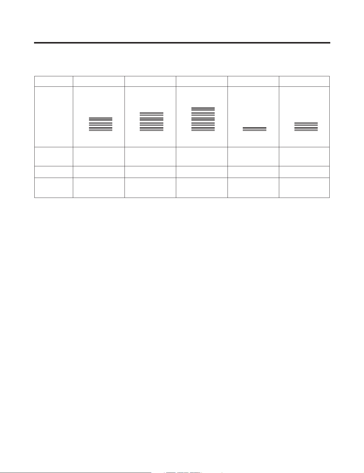
2. Refrigerator Functions
2-1-1. Temperature Selection (LRSC26944**, LRSC26980TT)
Division Power Initially On 1st Press 2st Press 3th Press 4th Press
Setting
temperature
Temperature
Control
Freezer Control
Refrigeration
Control
* The temperature can vary ±3 °C depending on the load condition.
5
4
3
2
1
Medium Medium Cold Coldest Warmest Medium Warm
-2 °F -5 °F -8 °F 7 °F 4 °F
37 °F 34 °F 32 °F 46 °F 41 °F
5
4
3
2
1
5
4
3
2
1
5
4
3
2
1
5
4
3
2
1
❉ Whenever pressing the button, setting is repeated in the order of (Medium) ➝ (Medium Cold) ➝ (Coldest) ➝ (Warmest) ➝
(Medium Warm).
• The actual inner temperature varies depending on the food status, as the indicated setting temperature is a target
temperature, not the actual temperature within the refrigerator.
• A newly installed refrigerator will take 24 hours minimum for temperatures to stabilize. The temperature should be
checked and adjusted as necessary after 2 or 3 days.
2-1-2. LCD Back Light Control (LRSC26944**, LRSC26980TT)
1. In order to see the LCD display more easily, the backlight is turned on for one minute at the initial application of power, for
20 seconds when buttons are pressed, when a door is opened, and for 20 seconds after the door is closed.
2. When any display button is pressed while the backlight is off, the bell sounds and the backlight is turned on, but the
button function is not performed. In other words, pressing any button turns on the backlight but does not cause any
function to be initiated.
3. To check the LCD graphic and back light ON/OFF status, press and hold the EXPRESS/JET FRZ and FREEZER buttons.
This will turn the back light on and illuminate all of the graphics. When the buttons are released, the graphic display
returns to its previous setting and the back light is turned off.
2-1-3. Room temperature display function
1. The sensor for the ROOM TEMP display is located under the upper right hinge cover. Factors such as air flow, lighting,
and other appliances operating within the room, may cause the display to differ from other temperature displays in the
same room.
2. Ambient temperature is displayed between 16°F and 120°F. Temperatures 15°F and below are displayed as Lo and
temperatures 121°F and above are displayed as Hi. If the ambient temperature sensor fails, Er will be displayed.
- 19 -
Page 20
MICOM FUNCTION
DISPENSER & KEY
3 SECS
LOCK
DISPENSER & KEY
3 SECS
LOCK CONTROL
DISPENSER & KEY
3 SECS
LOCK
DISPENSER & KEY
3 SECS
LOCK CONTROL
Ex) Select
LOCK
Ex) Select
LOCK again
Ex) Select
LOCK
Ex) Select
LOCK again
In initial
Power On
Classification
Filter Status
Display
Pass of
a month
Pass of
2 months
Pass of
3 months
Pass of
4 months
Pass of
5 months
Pass of
6 months
3 SECS
FILTER
MONTH
FILTER
MONTH
FILTER
MONTH
FILTER
MONTH
FILTER
MONTH
FILTER
MONTH
FILTER
MONTH
FILTER LIGHT
In initial Power On
/ Filter RESET
Replace indicator
light on
Classification
Filter Status
Display
FILTER
FILTER RESET
HOLD 3SECS
FILTER
3 SECS
FILTER LIGHT
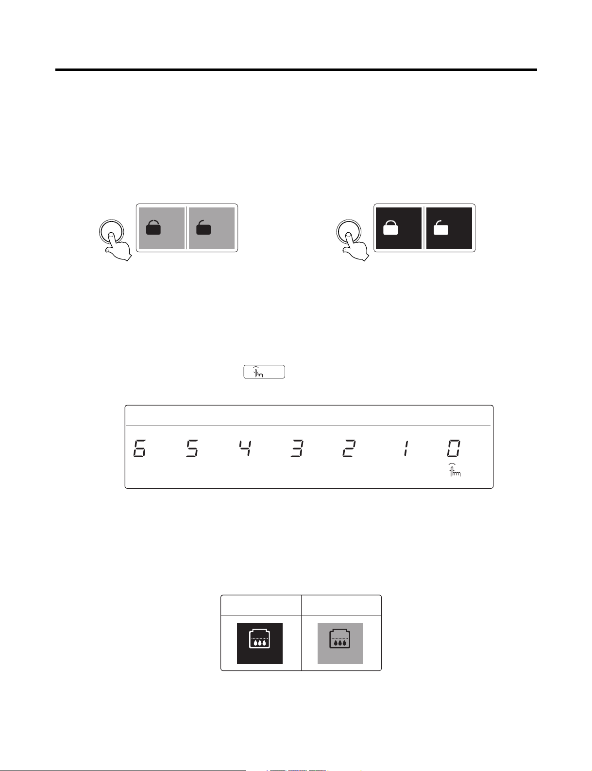
2-1-4. Lock function (dispenser and display button lock)
1. When the refrigerator is first powered up, the Lock function is turned off.
2. To lock the display, the dispenser, and the control panel, press and hold the LOCK button for more than 3 seconds. The
LOCK text on the display will be turned on.
3. To unlock the controls, press and hold the lock button for more than 3 seconds. The LOCK text on the display will be
turned off.
LCD (LRSC26944**, LRSC26980TT) LED (All models except LRSC26944**, LRSC26980TT)
2-1-5. Filter condition display function
LCD (LRSC26944**, LRSC26980TT)
1. This units displays the months left before the water filter needs to be changed. It starts when the unit is first plugged in.
2. After 6 months have passed the filter change will appear on the display. It will show FILTER LIGHT 3 SECS.
3. Press and hold the filter button for 3 seconds to reset the filter timer.
LED (All models except LRSC26944**, LRSC26980TT)
1. There is a replacement indicator light for the water filter cartridge on the dispenser.
2. The water filter should be replaced every six months or about 28,000 seconds' filtering time.
3. The water filter light and FILTER RESET HOLD 3 SECS will show in the display to remind you to change the filter soon.
4. After replacing the filter, press and hold the lock button for more than 3 seconds. The FILTER RESET HOLD 3 SECS will
turn off.
- 20 -
Page 21
MICOM FUNCTION
DISPENSER
LCD LED
CUBE
WATER
CRUSH
CUBE
WATER
CRUSH
Pressing
Switch
LCD (LRSC26944**, LRSC26980TT)
LED (LRSC26930**)
LED (LRSC26910**, LRSC26911**, LRSC26920**, LRSC26922**)
EXPRESS/JET FRZ
OFF
EXPRESS FRZ
JET FRZ
EXPRESS/JET FRZ
EXPRESS
JET
EXPRESS FRZ
ON
OFF
Dispenser Iight OFF
LCD
Dispenser Iight ON
LCD
Dispenser Iight ON/OFF
LED
CN
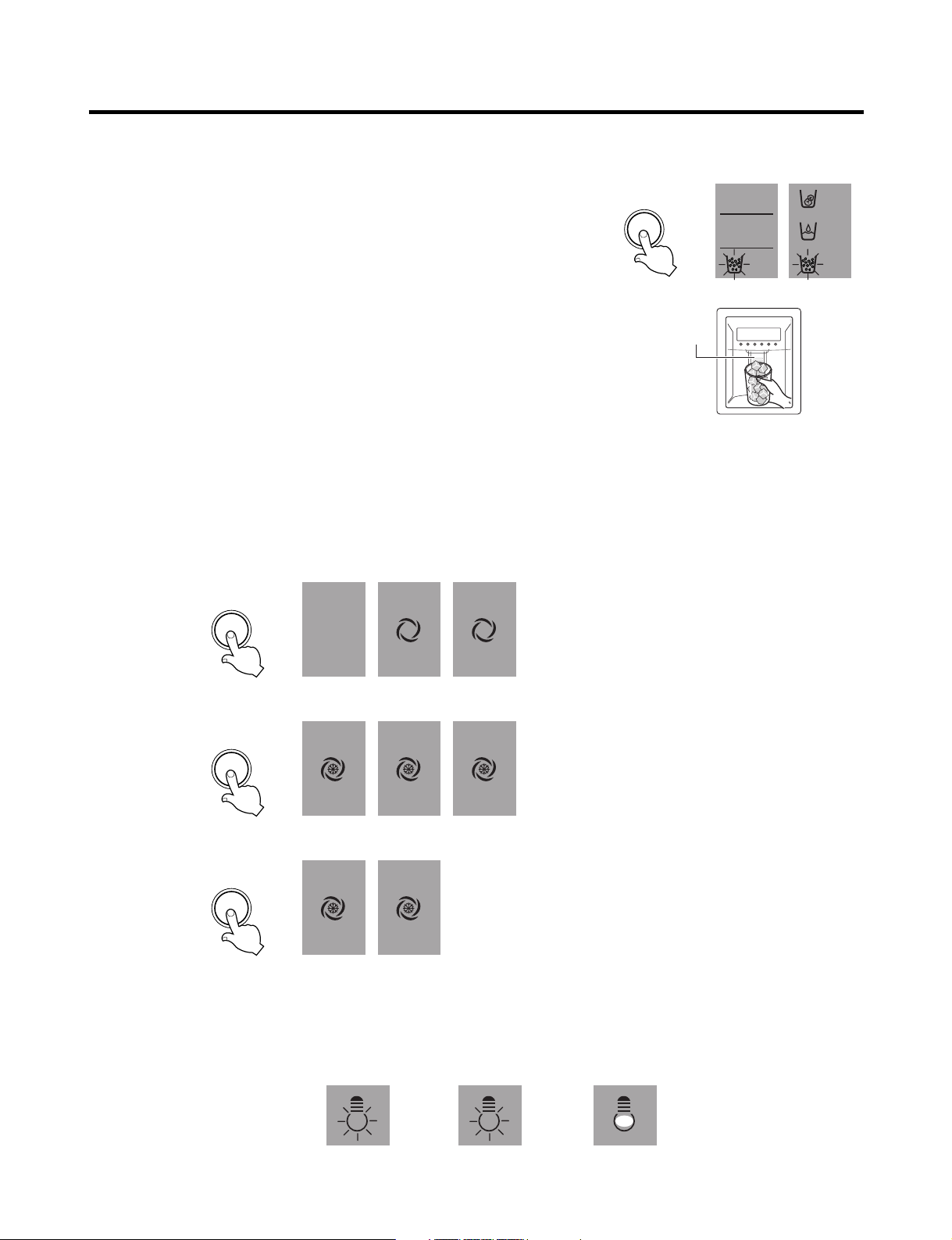
2-2. Dispenser use selection
You can select water or ice.
❉ Select water, crushed ice, or ice cubes by cycling through the selections when
pressing the DISPENSER button.
❉ Hold your cup in the dispenser for a few seconds after dispensing ice or water to
allow the last pieces of ice or drops of water to fall into the cup.
2-3. Express freezing/JET freezing selection
Please select this function for prompt freezing.
• The functions are cycled in the order shown below when the EXPRESS/JET FRZ button is pressed.
• The arrow mark graphic remains at the On status after flickering 4 times when selecting Special Refrigeration EXPRESS
FRZ or JET FRZ.
• EXPRESS FREEZE and JET FREEZE operate for a set time and then default to normal freezer operation.
2-4. Dispenser Light
• Dispenser switch or dispenser light button turns the dispenser light in the dispenser on and off.
• The dispenser light turns off automatically after 7 minutes.
- 21 -
Page 22

MICOM FUNCTION
2-5. Express freezing
1. EXPRESS FREEZING improves the cooling speed of the freezer by running the compressor and the freezer fan.
2. In the event of power failure, EXPRESS FREEZING is cancelled and the freezer defaults to normal operation.
3. The temperature setting is not changed when EXPRESS FREEZING is selected.
4. The freezer compartment and refrigerator temperature settings can be changed even when EXPRESS FREEZING is
selected and the cycle is underway.
5. The refrigerator compartment will operate at its usual setting even when EXPRESS FREEZING is selected or in progress.
6. If you select EXPRESS FREEZING, the refrigerator will default to its original setting at the end of the cycle.
7. If the defrost cycle is scheduled to come on while EXPRESS FREEZING is selected, EXPRESS FREEZING will operate
only for the time that is not used by the defrost setting.
8. If you press EXPRESS FREEZING during the defrost cycle, the EXPRESS FREEZING indicator will turn on but the cycle
will not run until the defrost cycle is completed.
9. If you press EXPRESS FREEZING within 7 minutes of the compressor’s last run cycle, the EXPRESS FREEZING cycle
will not begin until the 7 minute delay is complete.
10. The freezer fan runs at high speed when Express Freezing is selected.
2-6. Jet Freezing
1. Jet Freezing improves the cooling speed of the Jet Freezing Compartment by running the compressor and the Jet
Freezing Compartment fan.
2. If there is a power failure, the Jet Freezing cycle is released and the freezer defaults to its original setting.
3. If Jet Freezing is selected, the compressor (after the compressor delay time has passed) and the freezer fan will be
turned on. The temperature in the freezer will drop and the fan motor will be turned off for a set time, but the Jet Freezing
fan will run for no more than two hours. After that, the Jet Freezing function is terminated and the freezer defaults to its
original setting.
4. To keep the fan motor from freezing, it is switched on for 10 seconds once an hour.
5. The fan motor of jet freezing box will not be detected as a failure. (dc 12v operation)
6. When checking the Jet Freezing function, the Jet Freezing Compartment fan motor is switched on for 1 minute if the
freezer adjustment button or the Express Freeze button is pressed for more than one second.
- 22 -
Page 23

MICOM FUNCTION
°F / SET TEMP
/ TIME REMAINING
MIN
WINE
3.0
1.5
0.5
EXPRESS
CHILL
THAW(lbs)
FRUIT
VEGE
CHILED
ROOM
PARTIAL
FREEZING
SELECT SELECT
HR
2-7. OptiChill Function
uu
LRSC26944**, LRSC26980TT
2-7-1. OptiChill Temperature Control
1. The Optichill is positioned at the bottom of the refrigerator compartment. It allows the user to select a more specific
temperature based on the foods being stored, such as meat, fish, fruits and vegetables, etc.
2. The Optichill system consists of a sensor at the rear of the drawer, a damper, a fan motor between the Optichill
compartment and the freezer, a heater at the bottom of the Optichill compartment, and a temperature adjustment display
at the top.
3. The initial setting of the Optichill will be FRUIT VEGE.
4. Each time you press the SELECT button, the selection cycles through the settings in the order of FRUIT VEGE
(39°F)→CHILLED ROOM (30°F)→PARTIAL FREEZING (27°F)→WINE(50°F)→FRUIT VEGE (39°F). The display will show
the target temperature. If EXPRESS CHILL or THAW is selected, the selected temperature and NOTCH LED are not
shown, and the temperature can be adjusted.
5. The Optichill sensor detects the temperature and relays this information to the MICOM. Based on the temperature and
setting, The damper is opened or closed and the heater is on or off, as the conditions warrant.
6. If the Optichill damper hasn’t moved within an hour, it is automatically opened or closed and then returned to its previous
setting to keep it from freezing in one position.
7. In Display Check mode, the Optichill fan motor is turned on for one minute. To enter the Display Check mode, press and
hold both the Freezer Adjust button and the Express Freezing button for three seconds.
8. If the Optichill fan motor hasn’t run within an hour, it is automatically run for ten seconds once every hour to keep it from
freezing in one position.
NOTCH
Partial
Freezing
Display 27°F30°F39°F50°F
Chilled
Room
Fruit
VEGE
Wine
- 23 -
3.0lbs 1.5lbs
12Hr 8Hr 4Hr 90Min 50°F
THAW
0.5lbs
Express
Chill
Function
Page 24

MICOM FUNCTION
2-7-2. OptiChill Thawing & Express Chill Control
1. When you press the SELECT button on the right, the THAW LED will light. The time for the selected function will be
shown. You can cycle through the options in this order: EXPRESS CHILL/THAW OFF→EXPRESS CHILL (90 Min.)→
THAW 0.5 lbs. (4 hours)→THAW 1.5 lbs. (8 hours)→THAW 3.5 lbs. (12 hours)→EXPRESS CHILL/THAW OFF.
If EXPRESS CHILL/THAW is selected, the NOTCH temperature in the Optichill will not be displayed.
2. If EXPRESS Chill is selected, the Optichill damper is opened and the fan motor is turned on. If the Optichill does not
reach the set temperature after no more than ninety minutes, the setting is released.
3. The Optichill will count down from 90 minutes and show the remaining time in minutes.
4. When the EXPRESS CHILL cycle ends (or is released), the setting defaults to FRUIT VEGE (39°F).
5. If THAW is selected, the Optichill damper is closed and the time and temperature will be set according to the thawing
function selected. The thawing function will be automatically terminated at the end of the set time.
6. When in THAW mode, the sensor controls the heater to keep the set temperature.
7. When in THAW mode, the display counts down the remaining time in minutes.
8. When the THAW mode is released, the Optichill automatically defaults to CHILLED ROOM (30°F).
uu
LRSC26930**
2-7-3. OptiChill Temperature Control
1. The Optichill is in the bottom of the refrigerator compartment and allows the user to select and adjust the temperature
based on the type food stored there. Selections include meat, fish, fruits and vegetables, etc. Storing foods at the proper
temperature allows them to be stored for longer periods.
2. The Optichill consists of a temperature sensor, a damper between the Optichill and the freezer, and a temperature
control/display at the top.
3. At initial power-up, the Optichill defaults to FRUIT VEGE. If the refrigerator door is opened, the Optichill LED will be on.
4. When you press the SELECT button on the left, the LED will light and indicate the setting. The time for the selected
function will be shown. You can cycle through the options in this order: FRUIT VEGE (39°F)→CHILLED ROOM→PARTIAL
FREEZING→FRUIT VEGE. The display will indicate the temperature for the selected setting.
5. The Optichill sensor detects the temperature and relays that information to the MICOM. When the set temperature is
reached, the Optichill damper is closed. If the temperature rises, the damper is opened to allow the temperature to fall
again.
6. If the Optichill damper hasn’t moved within an hour, it is automatically moved and returned to its original setting once
every hour to keep it from freezing in one position.
- 24 -
Page 25
MICOM FUNCTION
Doors of freezing /
cold storage room
or home bar
BUZZER
Closing
Opening
Within
a minute
A minute
30
seconds30seconds30seconds
Opening
Closing Closing
3 Times 3 Times 3 Times 3 Times
2-8. Variable freezing fan
1. To increase the cooling speed and load response speed, the MICOM will switches the freezer compartment fan motor
between high and regular speeds.
2. The MICOM runs the freezer fan at high speed only at initial power-up, Express Freezing operation, or in response to a
high load. The fan runs at the regular speed in all other circumstances.
3. When you open the refrigerator door while the fan is running at high speed, the MICOM will switch the fan to regular
speed. If you open the freezer door or the home bar door, the fan is switched off.
4. If the MICOM determines the fan is obstructed (the blade cannot turn) it switches the fan off. When there is no fan rotation
signal for 115 seconds, the MICOM displays an error on the display. To restart the fan, clear the obstruction and turn the
power off and back on.
2-9. Cooling fan motor
1. The cooling fan is switched ON and OFF in conjunction with the compressor.
2. The cooling fan runs at a single speed.
3. The Failure sensing method is the same as in the fan motor of the freezing fan motor (refer to failure diagnosis function
table for failure display).
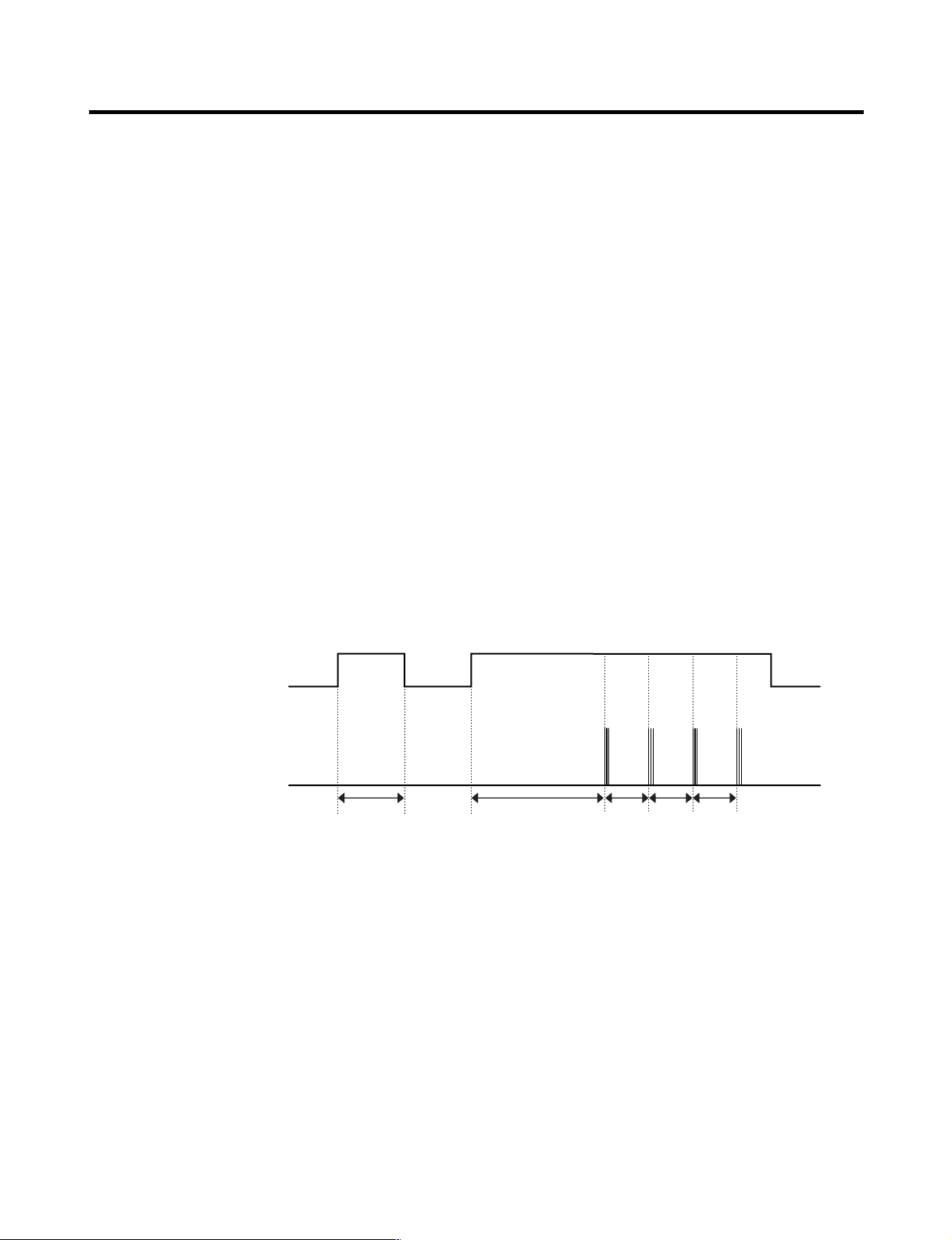
2-10. Door alarm
1. If the doors are left open for more than one minute, the buzzer sounds three 1/2-second tones at thirty second intervals for
four times.
2. If all the doors of freezing/cold storage room or home bar are closed during door open alarm, alarm is immediately turns
off.
2-11. Button selection buzzer bell
1. The DING sounds if you press any button on the front display.
- 25 -
Page 26

MICOM FUNCTION
2-12. Automatic Defrost Signal
1. The beep will sound if you press the test button on the main PCB.
2. The regular cycle sounds three short beeps one second apart.
3. When you select the automatic defrost cycle, the alarm sounds three series of three short beeps one minute apart.
2-13. Defrost Function
1. Automatic defrost is performed whenever the compressor run time totals 71/2 hours.
2. At initial power-up, the defrost cycle will run when the total compressor runtime is 4
3. Defrost is completed when the defrost sensor temperature rises above 41°F (5°C) during the defrost cycle. The defrost
cycle will terminate if the defrost sensor temperature does not achieve 41°F (5°C) within two hours.
4. The defrost cycle will not operate if the defrost sensor fails.
2-14. Refrigerator compartment lamp automatically off
1. The refrigerator light is turned ON and OFF by the refrigerator door switch.
2. If the refrigerator light is on for more than 7 minutes, it will be turned off automatically. It will operate normally if you close
the door and re-open it.
1
/2
hours.
- 26 -
Page 27
MICOM FUNCTION
POWER
ON
COMP
ON
F-FAN
&
C-FAN
ON
R-STEP
MOTOR
DAMPER
ON
OPTICHILL
STEP
DAMPER
MOTOR
ON
DEFROST
HEATER
OFF
DEFROST
HEATER
ON
DAMPER
&
DUCT DOOR
&
OPTICHILL
HEATER ON
DAMPER
&
DUCT DOOR
&
OPTICHILL
HEATER OFF
0.3
sec.
6.0
sec.
0.3
sec.
0.3
sec.
0.3
sec.
POWER
ON
0.3
sec.
PIPE
&
DISP'
HEATER
OFF
0.3
sec.
COMP
ON
0.3
sec.
F-FAN
&
C-FAN
ON
0.3
sec.
R-STEP
MOTOR
DAMPER
ON
0.3
sec.
OPTICHILL
STEP
DAMPER
MOTOR
ON
PIPE
&
DISP'
HEATER
ON
TEST
SWITCH
(PRESS
Once)
OTHER
LOAD
OFF
COMP
ON
F-FAN
&
C-FAN
ON
R-STEP
MOTOR
DAMPER
ON
OPTICHILL
STEP
DAMPER
MOTOR
CLOSE
TEST
SWITCH
(PRESS
2 Times)
COMP
OFF
F-FAN
&
C-FAN
OFF
FROST
REMOVAL
HEATER
ON
R-STEP
MOTOR
DAMPER
CLOSE
0.3
sec.
0.3
sec.
0.3
sec.
0.3
sec.
0.3
sec.
0.3
sec.
0.3
sec.
0.3
sec.
0.3
sec.
0.3
sec.
0.3
sec.
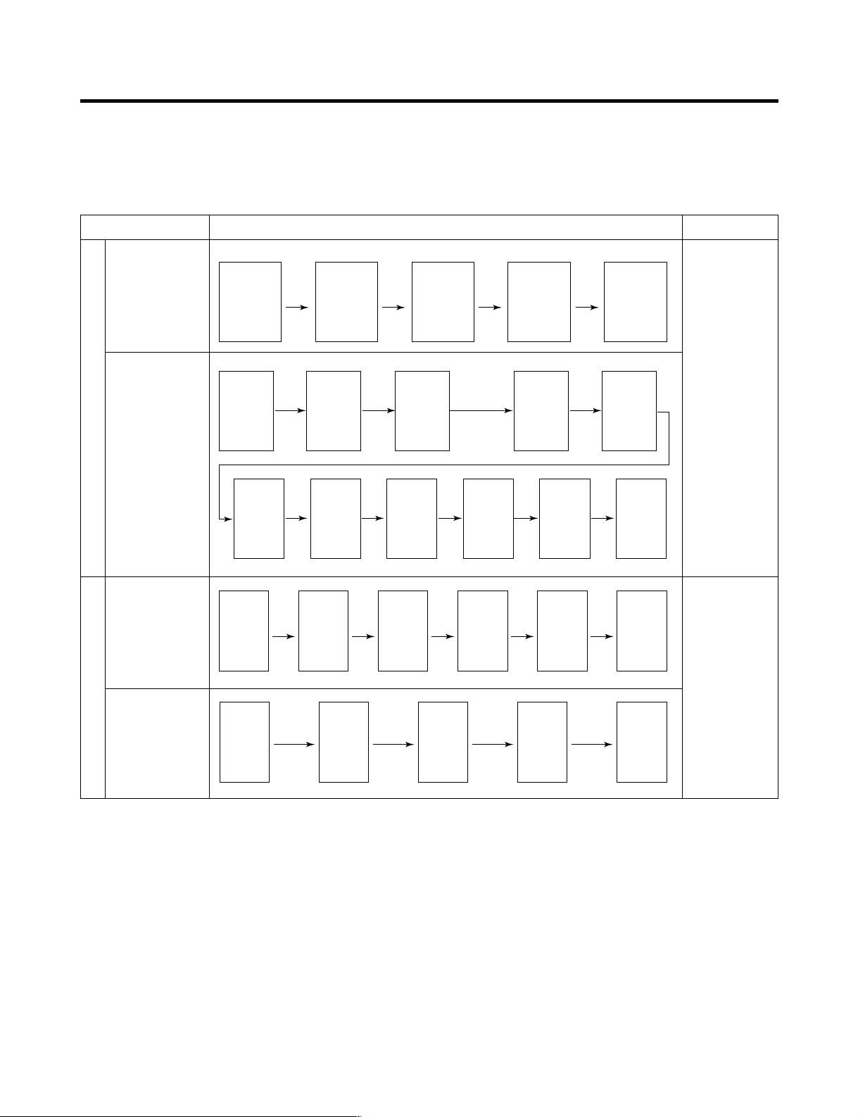
2-15. Sequential operation of components
Electromechanical parts of the appliance, such as the compressor, defrost heater, freezer fan, cooling fan, and damper
motor, are operated sequentially as shown in the chart below to prevent noise and circuit overload from everything starting
at once.
Function Load Operation Sequence Remark
When temperature
of a defrost sensor
becomes more
than 45°C
(initial setup,
movement)
In applying Initial power TEST MODE
When
temperature of a
defrost sensor
becomes less
than 45°C
(power failure,
service)
Test mode 1
(Compulsory
function)
Test mode 2
(Compulsory
defrost)
If error occurs
during operation,
initial operation is
not done.
Sequence of load
operation when
closing freezer
and refrigerator.
The refrigerator
will return to
normal operation
if you press the
test switch once
again while in
Test Mode 2 or if
the temperature
of the defrost
sensor surpasses
41°F (5°C). The
compressor will
run after the 7minute delay.
- 27 -
Page 28
MICOM FUNCTION
ICEBEAM
COOLING
OFF
CUBE
FILTER
MONTH
ROOM TEMP
DISPENSER & KEY
F
WATER 5
4
3
2
1
CRUSH
F F
3 SECS
EXPRESS
(On)
DIGITAL CONTROL
FRZ TEMP REF TEMP
(Off)
JET
CUBE
FILTER RESET
HOLD 3SECS
ROOM TEMP
LOCK
DISPENSER & KEY
WATER
CRUSH
3 SECS
F
C
F
C
F
C
FILTER
C
E
A B D C
FAILURE CODE
INDICATION PART
E
A B D
FAILURE CODE
INDICATION PART
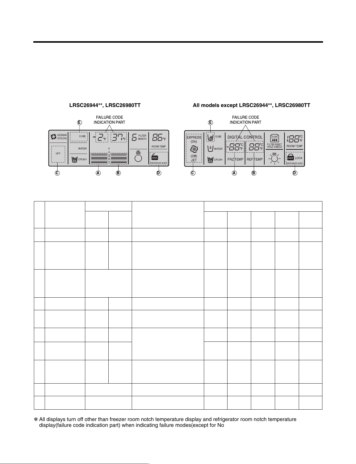
2-16. Failure Diagnosis
1. The failure diagnosis function indicates the area of a failure while the product is in operation.
2. When the appliance enters the failure mode, pressing buttons has no effect on the operation of the appliance.
3. If the error clears itself, the MICOM will reset and the appliance will operate as usual.
4. The failure code will be displayed as indicated in the drawings below. All other graphics and displays will be turned off.
LRSC26944**, LRSC26980TT All models except LRSC26944**, LRSC26980TT
●●
Failure code indication part
No. Item
1
Abnormal
freezer sensor
2
Abnormal refrigerator
Freezer notch
temperature
Refrigerator notch
temperature
display
Er FS
Er rS
display
Contents of failure
Freezer sensor short circuit
Refrigerator sensor1 short circuit
Compressor
ON for 15minutes /
OFF for 15minutes
sensor 1 (R1)
(Upper part in the
refrigerator
compartment)
3
Abnormal refrigerator
sensor 2 (R2)
Normal display
(Note 2)
Refrigerator sensor2 short circuit
(Middle part in the
refrigerator
compartment)
Abnormal defrost
4
Er dS
Abnormal short circuit
sensor
Failed defrosting
5
Er dH
Defrost heater, temperature fuse short
circuit, unplugged connector(indicated
4 hour later after trouble)
Abnormal freezing
6
BLDC motor
Er FF
Motor defect, hooked of lead wire
to fan, contact of structures with
fan, short or open of lead
Abnormal cooling
7
BLDC motor
Er CF
wire(there is no signal of BLDC
motor more than 115 seconds in
operation of fan motor)
Communication
8
Errors.
Er CO
Short or open of lead wire
connecting between main PCB
and display PCB, transmission tr
and receiving part
Abnormal
9
ambient sensor
Abnormal
10
Optichill sensor
✽ All displays turn off other than freezer room notch temperature display and refrigerator room notch temperature
display(failure code indication part) when indicating failure modes(except for Note1, Note2).
Normal display
(Note 1)
Normal display
(Note 2)
Ambient sensor short circuit
Optichill sensor short circuit
Product operation status in failure
Freezing
BLDC motor
Standard
Cooling
BLDC motor
●●
RPM
Standard
●●
●●
RPM
Standard
●●
●●
RPM
Standard
●●
●●
RPM
Standard
●●
●●
RPM
●●
●●
OFF
Standard
●●
OFF
RPM
Standard
●●
●●
RPM
●●
●●
●●
●●
●●
●●
Defrost
Heater
●●
●●
●●
No defrost
●●
●●
●●
●●
●●
●●
: Proper operation
Stepping
motor damper
●●
Full opening for
10 minutes/
Full closing for
15 minutes
●●
●●
●●
●●
●●
●●
●●
●●
- 28 -
Page 29

MICOM FUNCTION
Note1) The freezer and refrigerator temperature displays are also used to display error codes. The exception is that when
the ambient temperature sensor fails, it shows Er in the ambient temperature display. All other display elements will
function normally.
Note2) The R2 sensor, Optichill sensor, and water tank sensor are not indicated in the error codes, but you can see these
errors by entering the test mode by pressing and holding the Freezer Temperature and Express/Jet Freezer buttons
simultaneously.
R2-sensor (middle room)
Optichill sensor
Water tank sensor
✻ LCD (LED) check function: LCD (LED) Press and hold the Express Freeze button and the Freezer Temperature
adjustment button to check the display. This will turn on the backlight and all display elements.
Release the buttons and the display will return to its usual state.
Normal: LED or LCD graphic on the (C) part turns on
Abnormal: LED or LCD graphic on the (C) part turns off
Normal: LED or LCD graphic on the (D) part turns on
Abnormal: LED or LCD graphic on the (D) part turns off
Normal: LEDs or LCDs graphic on the (E) part turns on
Abnormal: LEDs or LCDs graphic on the (E) part turns off
The other LED or
LCD Graphics
Turn On.
- 29 -
Page 30
MICOM FUNCTION
EXPRESS
DIGITAL CONTROL
FRZ TEMP REF TEMP
JET
CUBE
FILTER RESET
HOLD 3SECS
ROOM TEMP
LOCK
DISPENSER & KEY
WATER
CRUSH
3 SECS
F
C
F
C
F
C
FILTER
5
4
3
2
1
ICEBEAM
COOLING
CUBE
FILTER
MONTH
ON
ROOM TEMP
DISPENSER & KEY
WATER 5
4
3
2
1
CRUSH
3 SECS
EXPRESS FRZ
F
C
F
C
LOCK
F
C
JET
3 SECS
FILTER LIGHT
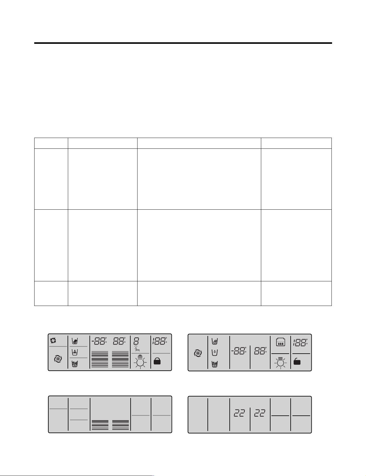
2-17. Test Function
1. The test function is a self-diagnostic system designed to detect problems early and to make diagnosis and repair easier
and quicker.
2. The test button is on the main PCB. Test mode can run for up to 2 hours and will then default to the normal operation
mode if not reset manually.
3. The function buttons are inoperable when the refrigerator is in test mode.
4. When you have finished using the test mode, reset the appliance manually by unplugging it for several seconds.
5. If nonconforming contents such as sensor failure are found during performance of test mode, release the test mode and
display the failure code.
6. The test button is inoperable if the display is showing failure codes. Reset the appliance manually to use the test button.
Mode Operation Contents Remarks
Test 1
Test 2
Normal
Status
Press test button once
(strong cold mode)
Press test button once at
the test mode 1 status
(forced defrost mode)
Press test button once at
the test mode 2 status
1. Continuous operation of compressor
2. Continuous operation of freezing BLDC motor
(high-speed RPM) and cooling BLDC motor
3. Defrost heater turns off
4. Stepping motor damper is completely opened
(baffle open)
5. Optichill stepping motor damper is completely
closed.
6. All display LEDs or LCD graphics turn on.
1. Compressor OFF
2. Freezing BLDC motor and cooling BLDC
motor turn off
3. Defrost heater turns on
4. Stepping motor damper is completely closed
(baffle close)
5. Optichill stepping motor damper is completely
closed.
6. All display LEDs or LCD graphics turn off.
Except for (A), (B) LCD graphic.
Except for (A): 22 (B): 22 LEDs.
Return to the initial status.
TEST MODE1 STATUS DISPLAY
Freezer fan is off when
door is open.
Return to the normal mode
when the defrost sensor is
above +5°C
Compressor will operate
after delay for 7 minutes
TEST MODE2 STATUS DISPLAY
- 30 -
Page 31

MICOM FUNCTION
2-18. Door-mounted Dispenser
1. This feature allows dispensing of ice and water without having to open the refrigerator door.
2. Select CUBES, CRUSHED ICE, or WATER. Then press the dispenser switch. The duct door is operated by a solenoid.
This door closes 5 seconds after ice is dispensed.
3. The dispenser does not work if the freezer door is open.
4. The dispenser will turn itself off after 3 minutes even if it does not receive an OFF signal. This prevents damage and
overheating of the motor. The duct door will close 5 seconds after ice is dispensed.
5. The dispenser lamp is turned on and off by the dispenser switch.
6. Selection of Cubes/Crushed/Water
1) Select Cubes/Crushed/Water using the selection button
2) The default at power-up is Crushed
3) The geared motor operates when Cubes or Crushed is selected.
7. Water Dispenser Function
1) Select Water using the selection button
2) The water line must be connected to the household water supply. The solenoid at the bottom right rear of the
refrigerator operates to supply water.
3) Press the dispenser switch to dispense water.
- 31 -
Page 32

EXPLANATION FOR MICOM CIRCUIT
1. Circuit Descriptions
1-1. Power circuit
LRSC269
The power circuit includes a Switched Mode Power Supply (SMPS). It consists of a rectifier (BD1 and CE1) converting AC
to DC, a switch (IC2) switching the DC voltage, a transformer, and a feedback circuit (IC3 and IC4).
Caution : Since high voltage (160 Vdc) is maintained at the power terminal, wait at least 3 minutes after unplugging the
Voltage of every part is as follows:
****
appliance to allow the current to dissipate.
Part VA1 CE1 CE2 CE3 CE4 CE5
Voltage 120 Vac 160 Vdc 14 Vdc 12 Vdc 15.5 Vdc 5 Vdc
- 32 -
Page 33

EXPLANATION FOR MICOM CIRCUIT
1-2. Oscillation circuit
The oscillation circuit generates a basic clock signal for synchronization and time calculation related to the transmission of
data and calculations made by the MICOM (IC1). The oscillator (OSC1) must always be replaced with an exact rated part,
because if this spec is changes, the time calculations of the MICOM will be affected and it might not work at all.
LRSC269
1-3. Reset circuit
The RESET circuit allows various parts of the MICOM, such as RAM, defrosting, etc., to be restarted from the initial state
when power is interrupted or restored. A LOW signal applied to the reset terminal for 10 ms causes the MICOM to reset
itself. During normal operation, the voltage at the reset terminal is 5 Vdc. If the reset fails, the MICOM will not operate.
LRSC269
****
****
- 33 -
Page 34

EXPLANATION FOR MICOM CIRCUIT
REF
REF
1-4. Load driving circuit
✽ The fan operates at the regular speed even if the door of the refrigerator or freezer is opened. When the doors are closed,
the fan reverts to its original speed.
✽ (A), (B), (C), and (D) of door switch for the freezer or refrigerator are connected to the door open sensing circuit in parallel
toward both ends of the switch.
✽ In the TEST mode, the fan will stop if any door is opened. It will resume operation when the door is closed.
LRSC269
Measuring part (IC6) IC6-14 IC6-10 IC7-16 IC6-13 IC6-11 IC6-12
****
Type of Load Compressor
Status
ON Within 1 V
OFF 12 V
Frost Removal
Heater
AC Converting
Relay
Refrigerator
LAMP
Dispensor
Heater
Magic room
Heater
- 34 -
Page 35

EXPLANATION FOR MICOM CIRCUIT
1-5. Dispenser operation circuit
Check load driving status
Type of Load
Measuring part IC7-15 IC7-14 IC7-13 IC7-12
Status
Lever Switch sensing circuit
Measuring part
Lever S/W
On(Press)
OFF 5V
ON Within 1 V
OFF 12 V
GEARED
MOTOR
5 V
0 V
SOLENOID
CUBE
IC1(Micom) (No. 16)
WATER VALVE
WATER
(60 Hz)
DISPENSER
- 35 -
SOLENOID
Page 36

EXPLANATION FOR MICOM CIRCUIT
1-6. Door sensing circuit
LRSC269
****
Measuring part
Door of Freezer / Refrigerator
Closing 5 V ( A - B , C - D . Switch at both ends are at Off status)
Opening 5 V ( A - B , C - D . Switch at both ends are at On status)
✽ Since door switches (A) and (B) are interconnected, if either fails, the other will not respond properly.
✽ If either switch fails, the light will not come on.
IC1 (MICOM) No. 47, 46 Pin
- 36 -
Page 37

EXPLANATION FOR MICOM CIRCUIT
1-7. Temperature sensing circuit
LRSC269
****
ROOM-SENSOR
WATER TANK
-SENSOR
FRZ-SENSOR
DEFROST-
SENSOR
REF-UPPER-
SENSOR
REF-LOWER-
SENSOR
OPTICHILL-
SENSOR
The circuits involving the freezer and refrigerator sensors control the temperature in both the freezer and the refrigerator.
The Icemaker sensor detects when ice is made. The defrost sensor determines both the need for defrosting and the
efficiency of the defrost operation. See the table below for voltages and checkpoints.
SENSOR CHECK POINT
NORMAL(-30 °C ~ 50 °C) IN
SHORT IN OPEN
Freezing sensor POINT A Voltage
Defrost sensor POINT B Voltage
Refrigerator sensor 1 POINT C Voltage
Refrigerator sensor 2 POINT D Voltage 0.5 V~4.5 V 0 V 5 V
Room temperature sensor POINT E Voltage
Water tank sensor POINT F Voltage
Optichill sensor POINT G Voltage
- 37 -
Page 38

EXPLANATION FOR MICOM CIRCUIT
P34
37
R25
CC10
223
R24
48
P47
P46
47
1-8. Switch entry circuit
The following circuits sense signal from the test switch, damper motor reed switch for testing and diagnosing the
refrigerator.
LRSC269
****
1-9. Option designation circuit (model separation function)
LRSC269
****
The circuits shown above vary according to which features are included on your particular model.
uThese circuits are preset at the factory and cannot be altered.
Separation Connection Status Application Standard
OP1
Connection OptiChill exist
OUT OptiChill doesn’t exist
- 38 -
Page 39

EXPLANATION FOR MICOM CIRCUIT
TA7774F
CON9
R56
R57 R58
INA
INB
A
B
A
B
CCW (Reverse rotation) (Positive rotation) CW
1-10. Stepping motor circuit
The motor is driven by magnetism formed in the areas of the coils and the stator. Rotation begins when a HIGH signal is
applied to MICOM Pin 33 of IC10 (TA7774F). This causes an output of HIGH and LOW signals on MICOM pins 34 and 35.
Explanation) The stepping motor is driven by sending signals of 3.33 mSEC via MICOM pins 33, 34, and 35, as shown in
the chart below. These signals are output via terminals 10, 11, 14, and 15 via input terminals 3, 6, and 8 of
IC10 (TA7774F), the motor drive chip. The output signals allow the coils wound on each phase of the stator to
form a magnetic field, which causes rotation. Input to the terminals INA and INB of IC10 as shown in the chart
below drives the motor.
- 39 -
Page 40

EXPLANATION FOR MICOM CIRCUIT
1-11. Fan motor driving circuit (freezer, mechanical area)
1. The circuit cuts all power to the fan drive IC, resulting in a standby mode.
2. This circuit changes the speed of the fan motor by varying the DC voltage between 7.5 Vdc and 16 Vdc.
3. This circuit stops the fan motor by cutting off power to the fan when it senses a lock-up condition.
LRSC269
****
a , d part b part e part c , f part
Motor OFF 5V 2V or less 2V or less 0 V
Motor ON 2 ~ 3V 12 ~ 14V 8 ~ 16V 0 V
COMPRESSOR
-FAN PWM
COMPRESSOR
-FAN LOCK
FREEZER-FAN PWM
FREEZER-FAN LOCK
- 40 -
Page 41

EXPLANATION FOR MICOM CIRCUIT
Temperature compensation at refrigerator
Temperature compensation at freezer
R16 R17
1-12. Temperature compensation circuit
LRSC269
****
Freezer Refrigerator
Resistance value Temperature Resistance value Temperature Remarks
(RCF1) compensation (RCR1) compensation
180 kΩ +5 °C [+9°F] 180 kΩ +2.5 °C [+4.5°F] Warmer
56 kΩ +4 °C [+7.2°F] 56 kΩ +2.0 °C [+3.6°F]
33 kΩ +3 °C [+5.4°F] 33 kΩ +1.5 °C [+2.7°F]
18 kΩ +2 °C [+3.6°F] 18 kΩ +1.0 °C [+1.8°F]
12 kΩ +1 °C [+1.8°F] 12 kΩ +0.5 °C [+0.9°F]
10 kΩ 0 °C [0°F] 10 kΩ 0 °C [0°F]
8.2 kΩ -1 °C [-1.8°F] 8.2 kΩ -0.5 °C [-0.9°F]
5.6 kΩ -2 °C [-3.6°F] 5.6 kΩ -1.0 °C [-1.8°F]
3.3 kΩ -3 °C [-5.4°F] 3.3 kΩ -1.5 °C [-2.7°F]
2 kΩ -4 °C [-7.2°F] 2 kΩ -2.0 °C [-3.6°F]
470 Ω -5 °C [-9°F] 470 Ω -2.5 °C [-4.5°F] Cooler
Reference temperature
u Temperature compensation table by adjustment value (difference value against current temperature)
Ex) If you change compensation resistance of (RCR1) from 10 kΩ (current resistance) to 18 kΩ (modified resistance), the
temperature will increase by +1°C[+1.8°F].
- 41 -
Page 42

EXPLANATION FOR MICOM CIRCUIT
u Temperature compensation table for the refrigerator is as follows:
Modification
resistance
Current
resistance
470Ω [0.9 °F] [1.8 °F] [2.7 °F] [3.6 °F] [4.5 °F] [5.4 °F] [6.3 °F] [7.2 °F] [8.1 °F] [9 °F]
2 kΩ [0.9 °F] [0.9 °F] [1.8 °F] [2.7 °F] [3.6 °F] [4.5 °F] [5.4 °F] [6.3 °F] [7.2 °F] [8.1 °F]
3.3 kΩ [1.8 °F] [0.9 °F] [0.9 °F] [1.8 °F] [2.7 °F] [3.6 °F] [4.5 °F] [5.4 °F] [6.3 °F] [7.2 °F]
5.6 kΩ [2.7 °F] [1.8 °F] [0.9 °F] [0.9 °F] [1.8 °F] [2.7 °F] [3.6 °F] [4.5 °F] [5.4 °F] [6.3 °F]
8.2 kΩ [3.6 °F] [2.7 °F] [1.8 °F] [0.9 °F] [0.9 °F] [1.8 °F] [2.7 °F] [3.6 °F] [4.5 °F] [5.4 °F]
Refrigerator
470 Ω 2 kΩ 3.3 kΩ 5.6 kΩ 8.2 kΩ 10 kΩ 12 kΩ 18 kΩ 33 kΩ 56 kΩ 180 kΩ
No 0.5 °C1 °C 1.5 °C2 °C 2.5 °C3 °C 3.5 °C4 °C 4.5 °C5 °C
change
0.5 °C No 0.5 °C1 °C 1.5 °C2 °C 2.5 °C3 °C 3.5 °C4 °C 4.5 °C
Down change
1 °C 0.5 °C No 0.5 °C1 °C 1.5 °C2 °C 2.5 °C3 °C 3.5 °C4 °C
Down
1.5 °C1 °C 0.5 °C No 0.5 °C1 °C 1.5 °C2 °C 2.5 °C3 °C 3.5 °C
Down Down Down
2 °C 1.5 °C1 °C 0.5 ° No 0.5 °C1 °C 1.5 °C2 °C 2.5 °C3 °C
Down Down Down
Up Up Up Up Up Up Up Up Up Up
Up Up Up Up Up Up Up Up Up
Down
change
Up Up Up Up Up Up Up Up
change
Drop
Up Up Up Up Up Up Up
change
Up Up Up Up Up Up
(RCR1) 2.5 °C2 °C 1.5 °C1 °C 0.5 °C No 0.5 °C1 °C 1.5 °C2 °C 2.5 °C
10 kΩ [4.5 °F] [3.6 °F] [2.7 °F] [1.8 °F] [0.9 °F] [0.9 °F] [1.8 °F] [2.7 °F] [3.6 °F] [4.5 °F]
Down Down Down Down Down
3 °C 2.5 °C2 °C 1.5 °C1 °C 0.5 °C No 0.5 °C1 °C 1.5 °C2 °C
12 kΩ [5.4 °F] [4.5 °F] [3.6 °F] [2.7 °F] [1.8 °F] [0.9 °F] [0.9 °F] [1.8 °F] [2.7 °F] [3.6 °F]
Down Down Down Down Down Down
3.5 °C3 °C 2.5 °C2 °C 1.5 °C1 °C 0.5 °C No 0.5 °C1 °C 1.5 °C
18 kΩ [6.3 °F] [5.4 °F] [4.5 °F] [3.6 °F] [2.7 °F] [1.8 °F] [0.9 °F] [0.9 °F] [1.8 °F] [2.7 °F]
Down Down Down Down Down Down Down
4 °C 3.5 °C3 °C 2.5 °C2 °C 1.5 °C1 °C 0.5 °C No 0.5 °C1 °C
33 kΩ [7.2 °F] [6.3 °F] [5.4 °F] [4.5 °F] [3.6 °F] [2.7 °F] [1.8 °F] [0.9 °F] [0.9 °F] [1.8 °F]
Down Down Down Down Down Down Down Down
4.5 °C4 °C 3.5 °C3 °C 2.5 °C2 °C 1.5 °C1 °C 0.5 °C No 0.5 °C
56 kΩ [8.1 °F] [7.2 °F] [6.3 °F] [5.4 °F] [4.5 °F] [3.6 °F] [2.7 °F] [1.8 °F] [0.9 °F] [0.9 °F]
Down Down Down Down Down Down Down Down Down
5 °C 4.5 °C4 °C 3.5 °C3 °C 2.5 °C2 °C 1.5 °C1 °C 0.5 °CNo
180 kΩ [9 °F] [8.1 °F] [7.2 °F] [6.3 °F] [5.4 °F] [4.5 °F] [3.6 °F] [2.7 °F] [1.8 °F] [0.9 °F]
Down Down Down Down Down Down Down Down Down Down
u Temperature compensation for the freezer is performed the same as for the refrigerator. The value for the freezer is twice
that of the refrigerator.
u This circuit enters the necessary level of temperature compensation for adjusting the appliance. The method is the same
for every model in this appliance family.
change
Up Up Up Up Up
change
Up Up Up Up
change
Up Up Up
change
Up Up
change
Up
change
- 42 -
Page 43

EXPLANATION FOR MICOM CIRCUIT
R18
R19
R20
R21
R22
R23
Compensation circuit for temperature of freezer
LRSC269
****
Temperature compensation in CUT
JCR1 +1 °C [+1.8 °F]
JCR2 +1 °C [+1.8 °F]
JCR3 -1 °C [-1.8 °F]
JCR4 -1 °C [-1.8 °F]
+2 °C [+3.6 °F]
-2 °C [-3.6 °F]
Compensation Compensation
for weak-cold for over-cold
JCR3 JCR4 JCR1 JCR2
CUT -1 °C [-1.8 °F]
CUT -1 °C [-1.8 °F]
CUT +1 °C [+1.8 °F]
CUT +1 °C [+1.8 °F]
CUT CUT -2 °C [-3.6 °F]
CUT CUT +2 °C [+3.6 °F]
CUT CUT 0 °C [0 °F]
CUT CUT 0 °C [0 °F]
CUT CUT 0 °C [0 °F]
CUT CUT 0 °C [0 °F]
CUT CUT CUT -1 °C [-1.8 °F]
CUT CUT CUT +1 °C [+1.8 °F]
CUT CUT CUT CUT 0 °C [0 °F]
Temperature compensation value
of refrigerator
0 °C (In shipment from factory)
Remarks
u This circuit allows adjustment of the set temperature for compensation by changing jumpers at locations JCR1~JCR4.
- 43 -
Page 44

EXPLANATION FOR MICOM CIRCUIT
ICEBEAM
COOLING
OFF
CUBE
FILTER
MONTH
EXPRESS/JET FRZ DISPENSER FREEZER REFRIGERATOR FILTER/LIGHT LOOK
ROOM TEMP
DISPENSER & KEY
F
WATER 5
4
3
2
1
CRUSH
F F
3 SECS
PWB ASSEMBLY DISPLAY
Main MICOM LCD(LED) dedicated MICOM
DC 12V
GND
Transmission (error status)
Reception (notch status)
Main PCB L/Wire FD/H(4-wires) Display PCB
1-13. Communication circuit
The following communication circuit is used for exchanging information between the main MICOM of the Main PCB and the
dedicated MICOM of the LED (LCD) Display PCB.
A bi-directional lead wire assembly between the two boards is required for the display to function properly.
Poor communication occurs if a continuous information exchange fails to last more than 2 minutes between main MICOM of
main PCB and LCD (LED) dedicated MICOM for LCD (LED) control of display PCB.
LRSC269
****
- 44 -
Page 45

EXPLANATION FOR MICOM CIRCUIT
Sensor resistance characteristics table
Measuring Temperature (°C) Freezing Sensor
-20 °C (-4 °F) 22.3 kΩ 77 kΩ
-15 °C (5 °F) 16.9 kΩ 60 kΩ
-10 °C (14 °F) 13.0 kΩ 47.3 kΩ
-5 °C (23 °F) 10.1 kΩ 38.4 kΩ
0 °C (32 °F) 7.8 kΩ 30 kΩ
+5 °C (41 °F) 6.2 kΩ 24.1 kΩ
+10 °C (50 °F) 4.9 kΩ 19.5 kΩ
+15 °C (59 °F) 3.9 kΩ 15.9 kΩ
+20 °C (68 °F) 3.1 kΩ 13 kΩ
+25 °C (77 °F) 2.5 kΩ 11 k Ω
+30 °C (86 °F) 2.0 kΩ 8.9 kΩ
+40 °C (104 °F) 1.4 kΩ 6.2 kΩ
+50 °C (122 °F) 0.8 kΩ 4.3 kΩ
Cold storage sensor 1&2
Frost removal sensor, Outside sensor
u Resistance value allowance of sensor is ±5%.
u When measuring the resistance value of the sensor, allow the temperature of that sensor to stabilize for at least 3 minutes
before measuring. This delay is necessary because of the sense speed relationship.
u Use a digital tester to measure the resistance. An analog tester has too great a margin of error.
u Resistance of the cold storage sensor 1 and 2 should be measured with a digital tester after separating CON8 of the
PWB ASSEMBLY and the MAIN part.
u Resistance of the freezing sensor shall be measured with a digital tester after separating CON7 of the PWB ASSEMBLY
and the MAIN part.
- 45 -
Page 46

EXPLANATION FOR MICOM CIRCUIT
DAMPER HEATER
OPTICHILL
OPTICHILL
STEPPING
MOTOR
OPTICHILL
SENSOR
PWB ASSEMBLY DISPLAY
JET/FREEZER
BOX FAN MOTOR
1-14. OptiChill stepping MOTOR/Display
LRSC26944**, LRSC26930**, LRSC26980TT
1-15. Jet freezing
LRSC26944**, LRSC26930**
- 46 -
Page 47

EXPLANATION FOR MICOM CIRCUIT
2. PWB parts diagram and list
2-1. PWB Assembly, main part diagram
LRSC269
****
- 47 -
Page 48

EXPLANATION FOR MICOM CIRCUIT
2-2. Parts list
LRSC269
****
- 48 -
Page 49

EXPLANATION FOR MICOM CIRCUIT
- 49 -
Page 50

EXPLANATION FOR MICOM CIRCUIT
2-3. LRSC26944**, LRSC26980TT
DISPLAY ASSEMBLY part diagram
- 50 -
Page 51

EXPLANATION FOR MICOM CIRCUIT
DISPLAY circuit diagram
- 51 -
Page 52

EXPLANATION FOR MICOM CIRCUIT
2-4. LRSC26910**, LRSC26911**, LRSC26920**, LRSC26922**, LRSC26930**
DISPLAY ASSEMBLY part diagram
- 52 -
Page 53

EXPLANATION FOR MICOM CIRCUIT
PWB ASSEMBLY DISPLAY
DISPLAY circuit diagram
- 53 -
Page 54

EXPLANATION FOR MICOM CIRCUIT
REF-
REF-
3. PWB Circuit Diagram may vary according to model.
LRSC269****
- 54 -
Page 55

EXPLANATION FOR MICOM CIRCUIT
ROOM-SENSOR
WATER TANK
-SENSOR
FREEZER-SENSOR
DEFROST-SENSOR
FRZ-DOOR SWITCH
JET FREEZER
BOX FAN MOTOR
PCB ASSEMBLY DISPLAY
PCB ASSEMBLY DISPLAY
REF-DOOR SWITCH
REF-UPPER-SENSOR
REF-LOWER-SENSOR
Only Models LRSC26944**, LRSC26980TT
DAMPER HEATER
OPTICHILL
OPTICHILL
STEPPING
MOTOR
OPTICHILL
BOX FAN MOTOR
OPTICHILL SENSOR
- 55 -
Page 56

OPERATION PRINCIPLE AND REPAIR METHOD OF ICEMAKER
• Adjusts EJECTOR to Start Position with power on.
Power On
Start Position
Icemaking
Mode
Dump
Mode
Park Position
Fill
Test Mode
• Waits until water becomes cold after starting the
ice making operation.
• Runs MOTOR to drop ice from the tray to the ICE BIN.
• Performs Icemaking Mode after supplying water by operating
the SOLENOID in ICE VALVE.
• To operate LINE and SERVICE, press and hold the water supply
control switch for 3 seconds. The icemaker will run through
3 stages:
Dump Fill Icemaking.
• With the detect lever, checks if the ICE BIN is full.
1. Operation Principle
1-1. Operation Principle of Icemaker
1. Turning the Icemaker stop switch off (O) stops the icemaking function.
2. Setting the Icemaker switch to OFF and then turning it back on will reset the icemaker control.
- 56 -
Page 57

OPERATION PRINCIPLE AND REPAIR METHOD OF ICEMAKER
Heater
on
off
on
0V
5V
off
30 sec.
10 sec.
Motor
Hall IC
Ice removing
completion point
2 ms
Icemaking sensor temperature is 50°F(10˚C)
or more
Max. 18 minutes
After detect LEVER rises
2. Control Method
2-1. Start Position
1. After POWER OFF or Power Outage, check the EJECTOR's position with MICOM initialization to restart.
2. How to check if it is in place:
- Check HIGH/LOW signals from HALL SENSOR in MICOM PIN.
3. Control Method to check if it is in place:
(1) EJECTOR is in place,
- It is an initialized control, so the mode can be changed to ice making control.
(2) EJECTOR isn't in place:
A. If EJECTOR is back in place within 2 minutes with the motor on, it is being initialized. If not, go to Step B.
B. If EJECTOR is back in place within 18 minutes with the heater on (to control Heater on its OFF condition), it is being
initialized. If not, it is not functioning. Repeat Step B with Heater and Motor off.
2-2. Icemaking Mode
1. Icemaking control refers to the freezing of supplied water in the ice trays. Complete Icemaking operations by measuring
the temperature of the Tray with Icemaking SENSOR.
2. Icemaking starts after completing fulfilled ice control and initial control.
3. The Icemaking function is completed when the sensor reaches 19°F(-7°C), 60 to 240 minutes after starting.
4. If the temperature sensor is defective, the Icemaking function will be completed in 4 hours.
2-3. Harvest with Dump Mode
1. Harvest with Dump control refers to the operation of dropping cubes into the ice bin from the tray when Icemaking has
completed.
2. Harvest with Dump control mode:
(1) Operates Heater for 30 seconds; then operate MOTOR.
(2) After performing Step 1 (to control the Heater on its off condition), Ice-Removal control will be back in place wthin 18
minutes. (Hall SENSOR sign = OV). Ice removal is then complete. Then change the mode to the water supply control.
If this control phase fails to start, it is not functioning. Put the Heater and Motor in the off position. Restart every 2
hours. (Refer to fig.1)
NOTE : If the motor malfunctions and starts before the detect lever rises, MICOM regards the Ice-Removing phase as
completed. Water then starts flowing. To prevent this, MICOM doesn’t switch to water-supply mode, but restarts the iceremoving mode. If this happens 3 times, the motor is malfunctioning and you should stop the loads (Heater, Motor). Then
restart the Ice-Removing mode every 2 hours. (See Step 2 above.)
- 57 -
Page 58

OPERATION PRINCIPLE AND REPAIR METHOD OF ICEMAKER
2-4. Fill / Park Position
1. When Ice-Removing control (Normal Ice-Removing control, Ice-Removing control for test) has completed, and the
EJECTOR is in place, this control operates the ICE SOLENOID by time check in the compressor enclosure of the
refrigerator. Then it supplies water to the ice making tray.
2. The water supply level is adjustable to 5 levels by pressing the water supply control switch. The selected level will
determine the fill time.
Water supply amount TABLE
STAGE TIME TO SUPPLY INDICATIONS REMARKS
1
2
3
4
5
4 sec.
4.5 sec.
5 sec.
5.5 sec.
6 sec.
The water amount will vary depending
on the water control Switch setting as
well as the water pressure of the
connected water line.
- 58 -
Page 59

OPERATION PRINCIPLE AND REPAIR METHOD OF ICEMAKER
2-5. Function TEST
1.
This is a compulsory operation for TEST, SVC, cleaning, etc. It is operated by pressing the water supply control KEY for 3 seconds.
2. It operates in the Icemaking mode, but not in the Ice-Removing mode or water supply process. (If there is an ERROR, it
can only be checked in the TEST mode.)
3. If the water supply control KEY is pressed for 3 seconds in the Icemaking mode (no matter what condition the Ice-Making
tray is in) the Ice-Removing operation starts immediately. Water is not yet frozen, so water is poured instead of ice. If the
control doesn’t operate normally in the TEST mode, check and repair as needed.
4. After water is supplied, the normal CYCLE is followed: Icemaking → Dump → Fill → Park Position.
5. When Stage 5 is completed in the TEST mode, minimize MICOM in 5 seconds, the time needed to supply water resets to
the previous status in the TEST mode.
Diagnosis TABLE
STAGE ITEMS INDICATOR REMARKS
1
2
3
4
5
6
HEATER
MOTOR
HALL IC (detection
of position) I
VALVE
(Detection of
ICE-FULL)
HALL IC (Detection
of ICE-FULL) II
reset
3. Defect diagnosis function
Mark previous status on TEST mode
Five seconds after heater starts, heater will
go off if temperature recorded by sensor is
10°C or lever is in up position.
Five seconds after heater starts, you can
confirm that motor is moving.
You can confirm Hall IC detection of position.
Two seconds after detection of initial
position, you can confirm that valve is on.
You can check whether hall is sensing Full
ice condition. (If there is a ICE-FULL error,
the fifth LED is not on.)
5 seconds after the last step is completed,
the icemaker resets itself to its initial state.
3-1. ERROR CODES shown on Ice Maker water supply control panel
NO DIVISION INDICATOR CONTENTS REMARKS
1
2
3
ERROR indicators in table can be checked only in TEST mode.
Normal
Icemaking
Sensor
malfunction
Icemaker Kit
malfunction
Mark time to
supply
Cut or short-circuited wire
When ejector blades doesn’t
reach park position in 18 minutes
None
after Dump Mode starts.
Display switch
operates properly
Make sure that the wire
on each sensor is
connected.
Defects of
HALL IC/MOTOR/
HEATER/RELAY/
STALLED EJECTOR.
- 59 -
Page 60

CIRCUIT
LRSC26944**, LRSC26980TT
- 60 -
Page 61

CIRCUIT
LRSC26930**
FREEZER
FREEZER
FREEZER
COMPRESSOR
REF-UPPER
REF-LOWER
REF
REF-DOOR
SWITCH
ICEMAKER
KIT
FREEZER-LAMP
FREEZER-DOOR
SWITCH
- 61 -
Page 62

CIRCUIT
LRSC26920**, LRSC26922**
FREEZER
FREEZER
FREEZER
COMPRESSOR
REF-UPPER
REF-LOWER
REF
REF
DISPENSER
LEVER SWITCH
FREEZER-DOOR
SWITCH
FREEZER-LAMP
- 62 -
Page 63

TROUBLE DIAGNOSIS
Troubleshooting
PROBLEM CAUSE/CHECK POINTS REMARKS
1. Faulty start
1) No power at outlet.
2) No power on cord.
Bad connection between adapter and outlet. (faulty adapter)
The Inner diameter of adapter.
The distance between holes.
The distance between terminals.
The thickness of terminal.
Bad connection between plug and adapter (faulty plug).
The distance between pins.
Pin outer diameter.
3) Shorted start circuit.
No power on
power cord.
Disconnected copper wire.
Internal electrical short.
Faulty terminal contact.
Disconnected.
Weak connection.
Short inserted cord length.
Worn out tool blade.
Power cord is disconnected.
Faulty soldering.
Loose contact.
- Large distance between
male terminal.
- Thin female terminal.
Terminal disconnected.
Bad sleeve assembly.
* Measuring instrument:
Multi tester
■ Check the voltage.
If the voltage is within ±85%
of the rated voltage, it is OK.
■ Check the terminal
movement.
■
Check both terminals of
power cord.
Power conducts:OK.
No power conducts:NG
OLP is off.
No electric power on compressor. - Faulty compressor.
Faulty PTC.
4) During defrost.
Capacity of OLP is small.
Characteristics of OLP is bad.
Bad connection.
Power is
disconnected.
Power does not conduct. - Damage.
Bad characteristics. - Initial resistance is big.
Bad connection with
compressor.
Bad terminal connection.
Start automatic defrost.
Cycle was set at defrost when the refrigerator
was produced.
Inner Ni-Cr wire blows out.
Bad internal connection.
Faulty terminal caulking (Cu wire is cut).
Bad soldering.
Too loose.
Assembly is not possible.
■ Check both terminals of
OLP
If power conducts:OK.
If not:NG.
■ Check the resistance of both
terminals.
At normal temperature 6:
OK.
If disconnected:∞.
- 63 -
Page 64

TROUBLE DIAGNOSIS
PROBLEM CAUSE/CHECK POINTS REMARKS
2. No cooling.
2) Refrigeration system is clogged.
Moisture
clogged.
No electric
power on
thermostat.
Weld joint
clogged.
Drier clogging.
Residual moisture
in the evaporator.
Residual moisture.
Insufficient drier
capacity.
Residual moisture
in pipes.
Moisture penetration - Leave it in the air. - Moisture penetration.
into the refrigeration oil.
Short pipe insert.
Pipe gaps.
Too much solder.
The capillary tube inserted depth. - Too much.
Capillary tube melts. - Over heat.
Clogged with foreign materials.
Reduced cross section by cutting. - Squeezed.
Too large.
Damaged pipes.
Air Blowing.
Leave it in the air.
Caps are missed.
Not dried in the compressor.
Elapsed more than 6 months after drying
Caps are missed.
No pressure when it is open.
Dry drier - Drier temperature.
Leave it in the air.
Caps are missed.
Air blowing.
Not performed.
Too short.
Impossible moisture
confirmation.
Low air pressure.
During rest time.
After work.
Check on package
condition.
Good storage after
finishing.
During transportation.
During work.
Not performed.
Performed.
Too short time.
Low air pressure.
Less dry air.
Desiccant powder.
Weld oxides.
Drier angle.
■ Heat a clogged evaporator to
check it. As soon as the
cracking sound starts, the
evaporator will begin to
freeze.
■ The evaporator does not cool
from the beginning
(no evidence of moisture
attached).
The evaporator is the same
as before even heat is
applied.
Foreign material clogging.
Compressor cap is disconnected.
Foreign materials are in the pipe.
- 64 -
Page 65

TROUBLE DIAGNOSIS
PROBLEM CAUSE/CHECK POINTS REMARKS
3. Refrigeration
is weak.
1) Refrigerant Partly leaked.
2) Poor defrosting capacity.
Drain path (pipe) clogged.
Defrost heater does not
generate heat.
Weld joint leak.
Parts leak.
Inject adiabatics into drain
hose.
Foreign materials
penetration.
Cap drain is not disconnected.
Parts
disconnected.
Adiabatics lump input.
Damage by a screw or
clamp.
Other foreign materials input.
Plate
heater
Cord
heater
Inject through the
hole.
Seal with drain.
Wire is cut.
- Heating wire.
- Contact point
between heating
and electric wire.
Dent by fin evaporator.
Poor terminal contacts.
Wire is cut.
- Lead wire.
- Heating wire.
- Contact point
between heating and
electric wire.
Heating wire is corroded
- Water penetration.
Bad terminal connection.
■ Check visually.
■ Check terminal
Conduction: OK.
No conduction: NG.
If wire is not cut, refer to
resistance.
P=Power
V=Voltage
R=Resistance
2
V
P= —
R
2
V
R= —
P
- 65 -
Page 66

TROUBLE DIAGNOSIS
PROBLEM CAUSE/CHECK POINTS REMARKS
3. Refrigeration
is weak.
Residual
frost.
No automatic defrosting.
Defrost does not return.
Weak heat from heater.
Too short defrosting time. Defrost Sensor.
Structural fault. Gasket gap.
Sheath Heater - rated.
Heater plate
Heater cord-L
- Faulty characteristics.
Seat-D (missing, location. thickness).
Air inflow through the fan motor.
Bad insulation of case door.
No contact to drain.
Loosened stopper cord.
Not touching the
evaporator pipe.
Location of assembly
(top and middle).
3) Cooling air leak.
Bad gasket adhestion
Door sag.
4) No cooling air circulation.
Faulty fan motor.
Bad adhesion.
Weak binding force at hinge.
Gap.
Bad attachment.
Contraction.
Fan motor.
Door switch.
Self locked.
Wire is cut.
Bad terminal contact.
Faults.
Refrigerator and freezer switch reversed.
Button is not pressed.
Contact distance.
Button pressure.
Melted contact.
Contact.
Poor door
attachment.
Door liner
(dimension).
Contraction inner
liner.
Misalignment.
Bad terminal
connection.
Adiabatics liquid
leak.
■ Check the fan motor
conduction: OK.
No conduction: NG.
- 66 -
Page 67

TROUBLE DIAGNOSIS
PROBLEM CAUSE/CHECK POINTS REMARKS
3. Refrigeration
is weak.
4) No cooling air circulation.
Faulty fan motor.
Small cooling air
discharge.
5) Compressor capacity.
Fan is
constrained.
Insufficient
motor RPM
Faulty fan.
Shorud. Bent.
Ice and foreign materials on rotating parts.
Fan shroud contact. - Clearance.
Damping evaporator contact.
Accumulated residual frost.
Fan overload. - Fan misuse.
Bad low termperature RPM characteristics.
Rated power misuse.
Low voltage.
Fan misuse.
Bad shape.
Loose connection. - Not tightly connected.
Insert depth.
Rating misuse.
Small capacity.
Low valtage.
6) Refrigerant
too much or too little.
7) Continuous operation
- No contact of temperature controller. - Foreign materials.
8) Damper opens continuously.
Foreign materials
jammed.
Failed sensor. - Position of sensor.
Characteristics
of damper.
9) Food storing place. - Near the outlet of cooling air.
Malfunction of charging cylinder.
Wrong setting of refrigerant.
Insufficient compressor. - Faulty compressor.
Adiabatics liquid dump.
The EPS (styrofoam) drip tray has sediment in it.
A screw or other foreign material has fallen into the drip
tray or damper.
Bad characteristics of its own temperatue.
Parts misuse.
Charge of temperature - Impact.
characteristics.
■ Check visually after
disassembly.
■ Check visually after
disassembly.
- 67 -
Page 68

TROUBLE DIAGNOSIS
PROBLEM CAUSE/CHECK POINTS REMARKS
4. Warm
refrigerator
compartment
temperature.
5. No automatic
operation.
(faulty
contacts)
1) Clogged cooling path.
Adiabatics liquid leak.
Foreign materials. –– Adiabatics dump liquid.
2) Food storage.
1) Faulty temperature sensor in freezer or refrigerator compartment.
Faulty contact.
Faulty temperature characteristics.
2) Refrigeration load is too much.
3) Poor insulation.
4) Bad radiation.
5) Refrigerant leak.
6) Inadequate of refrigerant.
7) Weak compressor discharging power.
8) Fan does not work.
9) Button is set at strong.
Store hot food.
Store too much at once.
Door open.
Packages block air flow.
Food.
Frequent opening and closing.
Cool air leak.
Poor door closing. – Partially open.
High ambient temperature.
Space is secluded.
Too much food.
Hot food.
Different rating.
Small capacity.
■ Inspect parts measurements
and check visually.
6. Condensation
and ice
formation.
1) Ice in freeezer compartment.
External air inflow. ––Bushing installed incorrectly.
Door opens
but not closes.
Gap around gasket. –– Contraction, distortion, loose, door twisted, corner not
Food vapor. –– Storing hot food. –– Unsealed food.
2) Condensation in the refrigerator compartment.
Door opens
but not closes.
Gasket gap.
3) Condensation on liner foam.
Cool air leak
and transmitted.
Weak door closing power.
Stopper malfunction.
Door sag.
Food hinders door closing.
fully inserted.
Insufficient closing.
Door sag.
Food hinders door closing.
Not fully filled.
Flange gap. –– Not sealed.
Gasket gap.
Top table part.
Out plate Ref/Lower part.
- 68 -
Page 69

TROUBLE DIAGNOSIS
PROBLEM CAUSE/CHECK POINTS REMARKS
6. Condensation
and ice
formation.
4) Condensation on door.
Condensation on the duct door. - Duct door heater is cut.
Condensation on the
dispense recess.
Condensation on the Not fully filled. Surface.
door surface. Corner.
Condensation
on the gasket
surface.
5) Water on the floor.
Condensation in the refrigerator compartment.
Defrosted water overflows. Clogged discharging hose.
Discharging hose Evaporation tray located at wrong place.
location.
Tray drip. Damaged.
Position of drain.
Recess Heater is cut.
Duct door is open. / Foreign material clogging.
Adiabatics liquid contraction.
Bad wing adhesion. Wing sag(lower part).
Door liner shape mismatch.
Corner. Too much notch.
Broken.
Home Bar heater is cut.
Breaks, holes.
Small Capacity.
Liquid shortage.
Liquid leak.
7. Sounds
1) Compressor compartment operating sounds.
Compressor sound Sound from machine itself.
inserted. Sound from vibration.
Restrainer.
Bushing Too hard.
seat. Distorted.
Aged.
Burnt.
Stopper. Bad Stopper Not fit
assembly. (inner
diameter
of stopper).
Tilted.
Not
Compressor base not connected.
Bad welding compressor stand(fallen).
Foreign materials in the compressor
compartment.
OLP
sound.
Capacitor noise.
Pipe sound. No vibration damper. Damping Bushing-Q.
Chattering
Insulation paper vibration.
Pipe contacts each other. – Narrow interval.
Capillary tube unattached.
sound.
Damping Bushing-S.
- 69 -
Page 70

TROUBLE DIAGNOSIS
PROBLEM CAUSE/CHECK POINTS REMARKS
7. Sounds
1) Compressor compartment operating sounds.
Transformer
Drip tray vibration sound.
Back cover machine sound.
Condenser drain sound.
2) Freezer compartment sounds.
Fan motor sound.
Sounds from fan
contact.
Unbalanced fan sounds.
sound.
Its own fault. –– Core gap.
Bad connection. –– Correct screw connection.
Bad assembly.
Distortion.
Foreign materials inside.
Bad connection.
Partly damaged.
Not connected.
Bad pipe caulking.
Normal operating sound.
Vibration sound.
Fan guide contact.
Shroud burr contact.
Damping evaporator contact.
Residual frost contact.
Unbalanced
Aged rubber seat.
Bad torque for assembling motor
bracket.
Damaged heater cord.
Narrow evaporator interval.
Surface machining conditions.
Fan distortion.
Misshappen.
Burr.
Ice on the fan. –– Air intake (opposite to motor
Motor shaft
contact sounds.
Resonance.
Evaporator noise.
3) Bowls and bottles make contact on top shelf.
4) Refrigerator roof contact.
5) Refrigerator side contact.
6) Insufficient lubricants on door hinge.
Supporter distorted.
Tilted during motor assembly.
Evaporator pipe contact. –– No damping evaporator.
Sound from refrigerant. –– Stainless steel pipe shape in
Sound from fin evaporator and pipe during expansion
and contraction.
bushing assembly.)
accumulator.
- 70 -
Page 71

TROUBLE DIAGNOSIS
PROBLEM CAUSE/CHECK POINTS REMARKS
8. Faulty lamp
(freezer and
refrigerator
compartment).
9. Faulty internal
voltage (short).
1) Lamp problem. Filament blows out.
Glass is broken.
2) Bad lamp assembly. Not inserted.
Loosened by vibration.
3) Bad lamp socket.
Disconnection. Bad soldering.
Bad rivet contact.
Short. Water penetration. Low water
level in tray.
Bad elasticity of contact.
Bad contact (corrosion).
4) Door switch. Defective.
Refrigerator and freezer switches are reversed.
Travel distance.
Bad connection.
Bad terminal contact.
Adiabatics liquid leak..
1) Lead wire is damaged.
Wire damage when assembling PTC Cover.
Outlet burr in the bottom plate.
Pressed by cord heater. lead wire, evaporator pipe.
2) Exposed terminal.
Compressor Compartment terminal. - Touching other
components.
Freezer compartment terminal. - Touching evaporator pipe.
3) Faulty parts.
Transformer. Coil contacts cover.
Welded terminal parts contact cover.
Compressor. Bad coil insulation.
Plate heater.
Melting fuse. Sealing is broken. Moisture penetration.
Cord heater. Pipe damaged. Moisture penetration.
Bad sealing.
Sheath heater.
■ Connect conduction and
non-conduction parts and
check with tester.
Conduction: NG.
Resistance∞: OK.
- 71 -
Page 72

TROUBLE DIAGNOSIS
PROBLEM CAUSE/CHECK POINTS REMARKS
10. Structure,
appearance,
and others.
1) Door foam.
Sag.
Hinge loose
Weak gasket
adhesion.
Fixed tape.
Bolt is loosened during
transportation.
Not tightly fastened.
Screw worn out .
Adhesion surface.
Not well fixed.
Noise during
operation.
Malfunction.
2) Odor.
Temperature of
refrigerator
compartment.
Deodorizer.
Food Storage.
Others.
Hinge interference.
Not closed Interference between door liner and inner liner.
Refrigerator
compartment is
opened when freezer
compartment is
closed (faulty stopper).
High. Faulty damper control.
No deodorizer.
Poor capacity.
Seal condition.
Storage of fragrant foods.
Long term storage.
Odors from cleaners or items which should not
be stored in a refrigerator.
Bigger door foam.
Hinge-Pin tilted-Poor flatness.
No washer.
No grease.
Stopper worn out.
Bad freezer compartment door
assembly.
No stopper.
Button is set at weak.
Door is open (interference by
food).
- 72 -
Page 73

TROUBLE DIAGNOSIS
low voltage). its specification.
Check the input voltage with a tester.
- Check other parts.
normal (capacitor, PTC, OLP), - Operates: Check other parts.
evacuate, and recharge refrigerant.
Auxiliary winding
apply power directly to the - Not operate: Replace the frozen
compressor to force operation. compressor with new one, weld,
Main winding
Power
contacted.
OLP It starts as soon as it is • Refer to weld repair procedures.
Problems Causes Checks Measures Remarks
11. Power
and adapter.
- Faulty connection between plug - Check visually. -Reconnect the connecting parts.
No power on - Power cord cut. - Check the voltage with a tester. -Replace the components.
outlet. - Faulty connector insertion. - Check visually. -Reconnect the connecting parts.
connected to high voltage. -
- Low voltage products are or visually. problem (ex. short, high voltage, fuse after confirming
- Short circuit by insects. (between power cord and products). - Replace with rated fuse.
Fuse blows out. - Short circuit by wrong connection. - Check the fuse with tester - Find and remove the cause of - Replace with rated
penetration).
- Electricity leakage. - Check the resistance of power cord ■ If fuse blows out
(tracking due to moisture and dust
- High voltage. with tester (if it is 0Ω, it is shorted). frequently, confirm
- Short circuit of components the cause and prevent.
-73-
Problems Causes Checks Measures Remarks
Compressor - Faulty PTC. - Check the resistance. - If resistance is infinite, replace it
12. Compressor
does not Vlaue:∞ is defective. with new one.
- Compressor is frozen. - If compressor assembly parts are - During forced operation:
operate. - If it is not infinite, it is normal.
Page 74

TROUBLE DIAGNOSIS
contact: Confirm deformation).
visually.
– Fan icing:
rotation.
- Rotate rotor manually and check
- Wire is cut.
terminal visually. (Repair and/or replace shroud if fan
- Bad terminal contact: Check - Maintain clearance and remove ice
- Fan constraint. – Fan shroud is constrained by shroud
Confirm visually.
- Faulty button pressure and contact:
attach sheets.
Press button to check operation.
button: Check visually. - Door liner bent:replace door or
- Door cannot press door switch - Door sag: fix door.
minimum). 50mm). performs while the
- Check dust on the grill in - Remove dust and contaminants refrigerator is on.
cleaner from the coils condenser
while the refrigerator is off.
compressor compartment. from grill for easy heat radiation.
- Check dust on the condenser coils. - Remove the dust with vacuum
Problems Causes Checks Measures Remarks
High Poor cool air circulation due to faulty - Lock –– Check resistance with a - Replace fan motor.
13. Temperature
temperature fan motor. tester.
in the freezer 0Ω: short.
compartment. ∞Ω: cut. - Reconnect and reinsert.
-74-
Faulty fan motor due to faulty door - Iced button (faulty) operation: - Confirm icing causes and repair.
switch operation. Press button to check - Replace door switch.
Bad radiation conditions in - Check the clearance between the - Keep clearance between - The fan may be
compressor compartment. refrigerator and wall (50 mm in refrigerator and walls (minimum broken if cleaning
Page 75

TROUBLE DIAGNOSIS
Weld the leaking part, recharge the Drier must be replaced.
compartment (high pressure side).
2. Check the end of compressor
sealing pipe (low pressure side).
(Cu + Fe / Fe + Fe).
3. Check silver soldered parts.
condenser pipe in compressor
compartment (cracks can
4. Check bending area of wire
happen during bending).
compartment and evaporators in
5. Check other parts (compressor
freezer compartment).
of evaporator in the freezer evacuate, and recharge the
compartment. refrigerant.
- If the frost forms evenly on the - No leaking, remove the remaining
surface, it is OK. refrigerant, and recharge new
- If it does not, it is not good. refrigerant.
Problems Causes Checks Measures Remarks
14. Cooling
High Refrigerant leak. Check sequence
temperature 1. Check the welded parts of the refrigerant.
in the freezer drier inlet and outlet and drier
compartment. auxiliary in the compressor
Shortage of refrigerant. Check frost formation on the surface - Find out the leaking area, repair, Drier must be replaced.
-75-
Page 76

TROUBLE DIAGNOSIS
seal refrigerant.
If it is not, compressor discharging weld, evacuate, and recharge
joints might be clogged. the refrigerant.
pipe is warm. condenser discharging line weld
If it is warm, OK. joints might be clogged.
If it is not, condenser outlet weld Disconnect with torch, remove the
2. Manually check whether hot line - If it's warm, OK. If it's not,
joints might be colgged. causes, evacuate, and recharge
condenser is warm, It is not warm
and the frost forms partly on the
evaporator in the freezer
compartment.
2. Check that cooling fan is damage and reassemble it.
and assembly sequence.
disconnected from the motor. ■ Refer to fan motor disassembly
Problems Causes Checks Measures Remarks
High Cycle pipe is clogged. Check sequence. - Heat up compressor discharging Direr must be replaced.
temperature in 1. Check temperature of condenser weld joints with touch, disconnect
the freezer manually. the pipes, and check the clogging.
compartment. If it is warm, OK. Remove the causes of clogging,
Leak at loop pipe weld joint Check sequence. Replace the compressor, weld, Drier must be replaced.
(discharge) in compressor. 1. Manually check whether evacuate, and recharge refrigerant.
-76-
Faulty cooling fan in the compressor Check sequence. - Replace if motor does not operate.
compartment. 1. Check cooling fan operation. - If fan is disconnected, check fan
Page 77

TROUBLE DIAGNOSIS
duct manually and assemble the
disconnected parts.
3) Check the water outlet.
4) Push the heater plate to suction
supply hot water until the ice in the
gap melts down.
bottom with hand and assemble
the disconnected parts.
2) Push the Heater plate to drain
1) Heating wire is damaged when 2. Check the resistance between lead wire is accessible to
the heating wire is cut or the circuit 0Ω: Short. ∞Ω: Cut. • Parts replacement: Refer to parts insulation tape and heat
is shorted. Tens to thousands Ω: OK. explanations. shrink tube if the cut
Problems Causes Checks Measures Remarks
15. Defrosting failure
No defrosting. Heater does not generate heat as 1. Check the resistance of heater. Heating wire is short and wire is cut. Seal the lead wire with
inserting into the evaporator. housing terminal and heater repair.
2) Lead wire of heater is cut. surface.
is cut. Tens to thousands Ω: Short.
3) Heating wire at lead wire contacts 0Ω: Short. ∞Ω: Cut.
(check drains outside). 2) Put in hot water to melt down frost.
2. Put hot water into the drain frost is severe.)
Suction tube and discharge orifice: 1. Confirm foreign materials. In case 1) Push out impurities by inserting
1. Impurities. of ice, insert the copper line copper wire. (Turn off more than
2. Ice. through the hole to check. 3 hours and pour in hot water if
Gap between Suction duct and 1. Confirm in the Suction duct. 1) Turn off the power, confirm
Heater plate (Ice in the gap). impurities and ice in the gap, and
Wrong heater rating (or wrong 1. Check heater label. Faults:replace.
(V: Rated voltage of user country)
(R: Resistance of tester[Ω])
2
V
substituting the resistance value Refer to main parts.
assembly). 2. Confirm the capacity after - How to replace :
R
into the formula.
P= ––
Compare P and lavel capacity.
Tolerance: ±7%
-77-
Page 78

TROUBLE DIAGNOSIS
with a new one.
2) Bad soldering. If ∞Ω: wire is cut. resistance with a tester.
Ice in the Suction duct. 1. Check the inner duct with mirror. 1) Turn power off.
1) Lead wire is cut. If 0Ω: OK. - Check wire color when maeasuring
Problems Causes Checks Measures Remarks
No defrosting Melting fuse blows. - Check melting fuse with tester. - Faullty parts: parts replacement.
1) Icing by foreign materials in the 2) Raise the front side (door side),
wire into the duct (soft and thin
2. Check by inserting soft copper 3) Reassemble the heater plate.
duct. support the front side legs, and let
the gap of heater plate. on, melt the frost by forced
2) Icing by cool air inflow through the ice melt naturally. (If power is
3) Icing by the gap of heater plate. defrosting.)
copper not to impair heating wire).
Bad cool air inflow and discharge, 1. Turn on power, open or close the 1) Check the faulty connector of
and bad defrosting due to faulty door, check that motor fan housing and reassemble wrongly
-78-
compartment, check the connection
around the housing visually,
defrost, and confirm heat generation
on the heater. Do not put hands on
contact and insertion (bad connector operates (If it operates, motor fan assembled parts.
insertion into housing of heater, is OK). 2) If the parts are damaged,
melting, fuse, and motor fan). 2. Disconnect parts in the refrigerator remove the parts and replace it
the sheath heater.
described in 1 & 2 (mechanical
model: disconnect thermostat
3. Check the parts which have faults
from the assembly).
Page 79

TROUBLE DIAGNOSIS
This interferes with cold
air circulation and
sublimation of the ice.
Problems Causes Checks Measures Remarks
16. Icing
Icing in the 1) Bad circulation of cool air. - Check the food is stored properly - Be acquainted with how to use. - Check the defrost
refrigerator - Clogged intake port in the (check discharge and intake port - Sealing on connecting parts. related parts if problem
compartment. refrigerator compartment. are clogged). - Check the damper and replace is caused by faulty
freezer and refrigerator
compartment.
2) Faulty door or refrigerator - Check gasket attached conditions. - Correct the gasket attachment - Replacement should
- Damper icing. - Sealing is not good. - Check icing on the surface of it if it has defects. defrosting.
pipe icing. - Bad defrosting. - Check icing at intake ports of evaporator and pipes.)
- Pipe icing. - Too much food is stored and clogs baffle and cool air path (pipe) after - Check defrost. (After forced
- Discharging the discharge port. dissembling the container box. defrosting, check ice in the
compartment. - Check door assembly conditions. conditions and replace it. be done when it
- Faulty gasket. - Door assembly and replacement. cannot be repaired.
- Faulty assembly.
3) Overcooling in the refrigerator - Check refrigerator compartment - Replace faulty parts.
-79-
compartment. is overcooled (when button
compartment. - Check parts are faulty.
- Faulty damper in the refrigerator pressed on weak).
- Faulty MICOM (faulty sensor)
- Heater wire is cut. after dissembling shroud and fan - Check defrosting. (Check ice on the on the evaporator but
- Defective defrost sensor. grille. evaporator and pipe.) can be sucked into the
4) Bad defrosting - Check frost on the evaporator - Check parts related to defrosting. - Moisture does not freeze
and refrigerator compartment. condenses and freezes.
- Defrosing cycle. - Check ice on intake port of freezer refrigerator, where it
5) Customers are not familiar with - Check food interferes with door - Be acquainted with how to use.
this machine. closing.
and high load.
- Door opens. - Check ice on the ceilings.
- High temperature, high moisture,
Page 80

TROUBLE DIAGNOSIS
Problems Causes Checks Measures Remarks
Ice in the freezer 1) Bad cooling air circulation. - Check food storage conditions - Be acquainted with how to use. - Check the parts related
grille. - Discharging port is Clogged. - Check food occupation ratio in defrosting). the faulty defrosting.
compartment. - Intake port is clogged in the freezer visually.(Check clogging at intake - Check defrost (Check ice on the to defrosting if the
- Surface of fan compartment. and discharging port of cooling air.) evaporator and pipes after forced problem is caused by
compartment. - Bad defrosting. - Check frost on the evaporator after
- Wall of freezer - Too much food is stored. volume (Less than 75%).
- Check icing at intake port of
3) Over freezing in the freezer - Refrigerator operates pull down. -Replace defective parts.
area.
discharging port.
- Cool air dissembling shroud and fan grille.
- Basket(rack) refrigerator compartment.
shute. - Faulty assembly - Check door assembly conditions. - Door assembly and replacement.
- Food surface. 2) Bad freezer compartment door - Check gasket attachment - Correct the gasket attachement - Replace when it can not
- Icing in the - Faulty gasket conditions. conditions and replace it. be repaired.
-80-
compartment is satisfactory, but
over freezing happens in the
- The Temperature of freezer
compartment. (Check if it is operated
- Faulty MICOM. intermittently)
refrigerator compartment even
though the notch is set at weak.
4) Bad defrosting. - Check frost on the evaporator after - Check parts related to defrosting.
- Heater wire is cut. dissembling shroud and grille. - Check defrosting. Check ice on the
- Faulty defrost sensor. - Check ice on the intake port in the evaporator and pipes after forced
- Defrosting cycle refrigerator compartment. defrosting.
use. - Check ice on the ice tray.
5) User is not familiar with how to - Check food holds door open. - Be acquainted with how to use.
- Door opens.
- High moisture food water is stored.
Page 81

TROUBLE DIAGNOSIS
along its route. Install a damper at
conditions (sagging and aging). 3) Touch the piping at various place
1.2 Check the bushing seat are sagged and aged.
and their interference. 4) Avoid pipe interference.
conditions in pipes. motor.
2.2 Check bushing inserting 5) Replace defective fan and fan
2.3 Touch pipes with hands or screw 6) Adjust fan to be in the center of
interfering parts and seal gaps in
-driver (check the change of the fan guide.
sound). 7) Leave a clearance between
structures. 9) Leave a clearance if evaporator
3.2 Check the interference with sound.
insertion and aging conditions.
3.3 Check fan motor. pipes and suction pipe touch
3.4 Check fan motor bushing freezer shroud.
4.2 Check drip tray leg insertion.
4.3 Check the screw fastening
conditions at condenser and
drip tray.
Problems Causes Checks Measures Remarks
17. Sound
operation. refrigerator. 2) Replace bushing and seat if they
Hiss sound 1. Loud sound of compressor 1.1 Check the level of the 1) Maintain horizontal level.
connected to the compressor. connected to the compressor the noise.
2. Pipes resonate sound which is 2.1 Check the level of pipes the point where your tuch reduces
-81-
compartment. blade damage. 8) Reassemble the parts which make
3. Fan operation sound in the freezer 3.1 Check fan insertion depth and the structures.
4. Fan operation sound in the 4.1 Same as fan confirmation in the
compressor compartment. refrigerator.
Page 82

TROUBLE DIAGNOSIS
Explain the principles of refrigeration
and that the temperature difference
between operation and defrosting
If evaporator pipe contacts with other
structures, leave a clearance between
can make sounds.
them (freezer shroud or inner case).
2)
tube touching in the compressor. on the shelves. 2) Leave a clearance where parts
compartment. 2-1. Touch pipes in the compressor interfere with each other.
2. Pipes interference and capillary 1-2. Check light food and container vibration is severe.
Problems Causes Checks Measures Remarks
Vibration sound. 1. Vibration of shelves and foods in 1-1. Remove and replace the 1) Reassemble the vibrating parts
Clack. the refrigerator. shelves in the refrigerator and insert foam or cushion where
3. Compressor stopper vibration. compartment with hands. 3) Reduce vibration with bushing
vibration. vibtates severely.
4. Moving wheel vibration. 2-2. Check capillary tube touches and restrainer if it is severe.
vibration. 3-1. Check compressor stopper 4) Replace compressor stopper if it
5. Other structure and parts cover back. (especially compressor and pipe).
moving wheels.
4-1. Check vibration of front and rear
5-1. Touch other structures and parts.
-82-
Irregular sound. 1. It is caused by heat expansion 1-1 Check time and place of sound 1)
shelves, and pipes in the
refrigerator.
Click. and contraction of evaporator, sources.
Page 83

TROUBLE DIAGNOSIS
compartment.
conditions on the evaporator and - Fasten the capillary tube to suction
- Check the sound of refrigerant at the - Check the restrainer attached on the
- Check the restrainer attachment capillary tube again (depth 15±3mm)
capillary tube weld joints. pipes or detach in the compressor
cycles.
- Explain the principles of freezing
accumulator with foam and restrainer.
Problems Causes Checks Measures Remarks
Sound Popping It happens when refrigerant expands
(almost the same at the end of capillary tube. initial installation. evaporator and capillary tube weld
as animals crying - Check the sound when the refrigerator joints and attach another restrainer.
sound). starts operation after forced defrosting. - If it is continuous and servere, insert
the pressure difference between - Check the sound when compressor is internal pressure difference.
condenser and evaporator. turned off. - If sound is servere, wrap the
Water boiling or It happens when refrigerant passes - Check the sound when compressor is - Explain the principles of freezing cycles
flowing sound. orifice in accumulator internal pipes by turned on. and refrigerant flowing phenomenon by
Sound of whistle When door closes, the internal pressure - Check the sound by opening and - Broaden the cap of discharge hose for
when door of the refrigerator decreases sharply closing the refrigerator or freezer doors. defrosting in the compressor
-83-
the refrigerator, making the whistle - Seal the gap with sealant between out
sound. and inner cases of hinge in door.
closes. below atomosphere and sucks air into compartment.
Page 84

TROUBLE DIAGNOSIS
wall are stained with food juice. - Store the food in the closed
- Check the shelves or inner with adequate ventilation.
with plastic wrap. - Clean the refrigerator and set
- Be sure food is securely covered container instead of vinyl wraps.
- Chedk food cleanliness. button at strong.
or odorous foods.
- It happens in the new refrigerator. plastic bag or wraps with wet food
deodorants.
- Remove and replace the
Problems Causes Checks Measures Remarks
18. Odor
odors. plastic bowl and bag. - Persuade customers not to use
Food Odor. Food (garlic, kimchi, etc) - Check the food is not wrapped. - Dry the deodorizer in a sunny place
Plastic Odor. Odors of mixed food and plastic - Check wet food is wrapped with - Clean the refrigerator.
Odor from the Odor from the old deodorizer. - Check the deodorizer odors. - Dry the deodorizer with dryer and *Deodorizer : option
deodorizer. then in the shiny and windy place.
-84-
Page 85

TROUBLE DIAGNOSIS
explanation.
dispenser.
Main PCB Test switch is PCB. circuit in circuit
pressed (or when both freezer explanation.
key and power freezer key are
pressed at the same time for
more than one second.)
Problems Symptom Causes Checks Measures Remarks
19. Micom
and display circuit. PCB to display PCB.
Bad PCB All display Bad connection Bad connector Visual check on connector Reconnect
electric power. LCD are off. between Main PCB connection from main connection. connector.
PCB transformer terminals with a tester. dispenser.
temperature fuse is (If resistance is infinity, trans
Defective PCB PCB transformer Check resistance of PCB Replace PCB Applicable to
transformer. winding is cut. transformer input and output transformer or PCB. model without
burnt out. winding is cut).
DefectivePCB electric Defective regulator IC Check voltage at input/output Replace regulator. Refer to electric
circuit parts. (7812, 7805). terminals. circuit in circuit
PCB electric terminal Check fuse in PCB electric Replace PCB fuse.
fuse is burnt out. terminal with a tester.
STR Parts are Check if STR No. 2 and 3 pins Replace parts. Applicable to
damaged. are cut when power is off. model with
-85-
terminal connection is contact terminal to
bad. Lead Wire.
Abnormal Bad connection Lead Wire connecting Check Lead Wire terminals Reconnect Lead
display LCD between Main PCB main PCB and display connecting Main PCB and Wire and directly
operation and display circuit. PCB is cut or connector display PCB with a tester. connect defective
Defective LCD. Defective LCD. Check if all LCD are on when Replace display Refer to display
Page 86

TROUBLE DIAGNOSIS
test switch once. It is OK if circuit
voltage is normal. explanation.
characteristics
table of sensor in
circuit. Refer to
tables on pages
40, 41, and 43.
driving circuits in
and circuit
(freezer,
refrigerator,
function.
& RY6 or PCB.
functions. diagnosis
Problems Symptom Causes Checks Measures Remarks
Bad cooling. Freezer Compressor does Compressor Lead Wire Check compressor Lead Wire Reconnect Lead
temperature is not start. is cut. with a tester. Wire.
high. Defective compressor Measure voltage at PCB CON2 Replace relay RY1 Refer to load
driving relay. (3&9) after pressing main PCB and RY2 or PCB. driving circuit in
Defective freezer Defective Freezer Check resistance of freezer Replace freezer Refer to
sensor. sensor parts. sensor with a tester. sensor. resistance
The wrong sensor Confirm the color of sensor in Repair main PCB explanation.
has been installed. circuits (main PCB sensor sensor housing
Order by model number housing).
-86-
and part number.
Defective freezer fan Fan motor lead wire Check fan motor lead wire Reconnect lead
• Defective door switch Measure the voltage between • Replace door Refer to load
motor. is cut. with a tester. wire.
home bar). motor after pressing test switch
(freezer, refrigerator, PCB power blue line and fan switch
driving relay. • Replace relay RY5
• Defective fan motor. of Main PCB. If the voltage is home bar). explanation.
• Defective fan motor normal, it is OK. • Replace fan motor.
Faulty defrost. Refer to faulty defrost items in trouble diagnosis Refer to trouble
Page 87

TROUBLE DIAGNOSIS
in circuit
explanation.
characteristic
damper or refrigerator
table in circuit
explanation.
wire are cut. Check Refer to Step Motor damper Replace Step Motor
Step Motor damper in parts repair guide. damper or refrigerator
part. control box Assembly.
Check Step Motor Refer to Step Motor damper Replace relay or Refer to single
Refrigerator Damper. damper motor and motor and reed switch lead wire.
temperature. reed switch and lead wire are cut with a tester.
damper Motor driving in parts repair guide. PCB. motor damper
relay in PCB. driving circuits
Check Step Motor damper Remove foreign
Foreign materials in Step
Motor damper baffles. baffle visually. materials.
Ice formation on Check if Step Motor damper Replace Step Motor
Step Motor damper Heater wire is cut with a
baffles. tester. control Box Assembly.
Defective refrigerator Defective refrigerator Check the resistance of Replace refrigerator Refer to sensor
sensor sensor parts. refrigerator sensor with a tester. sensor. resistance
Refrigerator sensor is Check the sensor color in the Repair main PCB
substituted for other circuit. (main PCB sensor sensor housing.
sensor. housing.)
Defective refrigerator Check if refrigerator sensor Fix again the
sensor assembly is not fixed at cover sensor but refrigerator sensor.
condition. inner case visually.
Problems Symptom Causes Checks Measures Remarks
Bad cooling Wrong Defective Step Motor Check Step Motor Check if Step Motor damper Reconnect lead
-87-
Page 88

TROUBLE DIAGNOSIS
characteristic
table of circuit
explanation.
structures.
working. tester. Wire.
with a tester after pressing main and RY 3) or PCB. driving conditions
PCB test switch twice. check in circuit
If the voltage is normal then it is OK. explanation.
Defective defrost driving relay. Check the voltage of CON2 (1 and 7) Replace relay (RY 7 Refer to load
with a tester. sensor. resistance
Defective defrost sensor parts. Check the resistance of defrost sensor Replace defrost Refer to sensor
rings or door Defective door switch parts. Refer to door switch in parts repair Replace door switch.
opening alarm guide.
does not work.
and buttons display PCB connecting lead wire. directly connect bad explanation.
do not contact terminal to
operate. lead wire.
Key is continuously depressed due to Disassemble frame display and confirm Adjust or replace
structural interference. visually. interfering
Problems Symptom Causes Checks Measures Remarks
Bad defrost. Defrost is not Defrost lead wire is cut. Check if defrost lead wire is cut with a Reconnect Lead
Defective Buzzer Defective connecting lead wire from Check lead wire related to door Repair lead wire.
buzzer continuously main PCB to door switch. switch with a tester.
-88-
Defective Buzzer does Key input wire is cut or bad connector Check input wire with a tester. Reconnect lead Refer to display
display button not sound terminal contact in main PCB and wire and replace or circuit in circuit
Page 89

TROUBLE DIAGNOSIS
and buttons function
do not operate. explanations.
continuously main PCB to door switch. switch. with dispenser.
rings or door Defective freezer compartment door Refer to door switch in parts repair Replace Freezer
opening alarm switch parts. guide. compartment door
does not work. switch.
output terminals with lever switch coupler IC or PCB.
pressed. It is OK if voltage change is
between 0V - 5V.
Defective photo coupler IC parts. Check voltage change at photo coupler Replace photo
dispensed. Defective lever switch parts Refer to door switch in parts repair guide. Replace lever switch.
Defective relay associated with ice Check relay (RY4, RY5, RY12) Replace defective
dispense (geared motor, cube, and with a tester. relay.
dispenser solenoid).
Defective parts associated with ice Check resistance of parts with a tester. Replace defective
dispense (geared motor, cube, and parts.
dispenser solenoid).
Defective relay associated with water Check relay (RY7) with a tester Replace defective
dispense. relay.
Defective parts associated with water Check resistance of parts with a tester. Replace defective
dispenser. parts.
Problems Symptom Causes Checks Measures Remarks
Defective Buzzer does Trouble mode indication. Check trouble diagnosis function. Repair troubles Refer to mode
display button. not sound indication in
Door Buzzer Buzzer Defective connecting lead wire from Check lead wire associated with door Repair lead wire. Check model
Bad water/ice Ice and water Defective connecting lead wire from Check Lead Wire associated with lever Repair lead wire.
dispenser. are not Main PCB to lever switch. switch with a tester.
-89-
Page 90

TROUBLE DIAGNOSIS
Cooling Cycle Heavy Repair
1. The Heavy Repair Standards for Refrigerator with R134a Refrigerant
NO. Items Unit Standards Purposes Remarks
1 Pipe and piping Min. Pipe:within 1 hour. To protect The opening time should be reduced to a
system opening time. Comp:within Moisture half of the standards during rain and
2 Welding. Nitrogen Weld under To protect - Refer to repair note in each part.
3N
2 sealed parts. Confirm N2 Confirm air leaking To protect - In case of evaporator parts, if it doesn't
4
Refrigeration
Cycle. time 40 minutes. moisture.
5 Refrigerant weighing. EA Use R134a Do not mix - Do not weigh the refrigerant at too hot or
6 Drier replacement.
Evacuation
Vacuum Torr Below 0.03(ref) Note:Only applicable to the model
degree equipped with reverse flow protect
Vacuum EA High and low Vacuum efficiency can be improved by
Vacuum EA Use R134a To protect The bushing pipes for R12 refrigerant shall
piping exclusive mixing of be melted when they are used for R134a
Pipe EA Use R134a To protect
coupler cxclusive. R12 Refri-
Outlet R134a exclusive.
(Socket)
Plug R134a exclusive
Pressure. Nitrogen oxide scale - R134a refrigerant is more susceptible to
leak. sounds when moisture make noise when removing bushing
Min. More than To remove
10 minutes. Penetration. rainy seasons (the penetration of water
Drier:within into the pipe is dangerous).
20 minutes.
atmosphere formation. leaks than R12 and requires more care
(N
2 pressure: during welding.
0.1~0.2 kg/cm
removing bushing penetration. cap blow dry air or N
cap. 1 min use the parts.
Sound:usable
No sound:
Pressure sides are operating compressor during evacuation.
evacuated at the
same time for
models above 200
manifold. mineral and refrigerant causes of leak.
exclusively. with R12 too cold an area. (25°C[77°F] is adequate.)
Weighing refrigerant. - Use copper charging canister
allowance:±5g Socket:2SV Plug: 2PV R134a
Note:Winter:-5g Note : Do not burn O-ring (rubber) during
Summer:+5g welding.
-
Use R134a exclusively
for R134a refrigerator
-
Replace drier whenever
repairing refrigerator
cycle piping.
2
) - Do not apply force to pipes before and
not usable
L
ester oils.
gerant mixing.
˝
˝
To remove
the moisture
from pipe.
after welding to protect pipe from
cracking.
2 gas for more than
plate.
7 Leak check. -Do not use soapy Detect -Check oil leak at refrigerant leak area.
water for check. refrigerant Use electronic leak detector if oil leak is
It may be sucked leak area. not found.
into the pipe. -The electronic leak detector is very
sensitive to halogen gas in the air. It also
can detect R141b in urethane. Please
practice, therefore, many times before use.
- 90 -
Page 91

TROUBLE DIAGNOSIS
2. Summary Of Heavy Repair
Process Contents Tools
Trouble
diagnosis
Remove refrigerant
Residuals
Parts
replacement
and welding
Vacuum
Refrigerant
charging and
charging
inlet welding
- Cut charging pipe ends and discharge refrigerant from Filter, side cutters
drier and compressor.
- Use R134a oil and refrigerant for compressor and drier Pipe Cutter, Gas welder, N
- Confirm N
Use good one for welding and assembly.
- Weld under nitrogen gas atmosphere. (N
0.1-0.2kg/cm
- Repair in a clean and dry place.
- Evacuate for more than forty minutes after connecting Vacuum pump R134a
manifold gauge hose and vacuum pump to high (drier) exclusively, Manifold gauge.
and low (compressor refrigerant discharging parts)
pressure sides.
- Evacuation Speed:113 liters/minute.
- Weigh and control the allowance of R134a charging R134a exclusive charging canister
canister in a vacuum conditions to be ±5 g with (mass cylinder), refrigerant
electronic scales and charge through compressor inlet R134a manifold gauge,
(Charge while compressor operates). electronic scales, pinch-off
- Weld carefully after pinching off the inlet pipe. plier, gas welding machine
2 sealing and packing conditions before use.
2 gas pressure:
2
).
2 gas
Check
refrigerant leak
and cooling
capacity
Compressor
compartment
and tools
arrangement
Transportation
and
installation
- Check leak at weld joints. Electronic Leak Detector,
Minute leak : Use electronic leak detector Driver (Ruler).
Big leak : Check visually.
Note:Do not use soapy water for check.
- Check cooling capacity
➀ Check radiator manually to see if warm.
➁ Check hot line pipe manually to see if warm.
➂ Check frost formation on the whole surface of the
evaporator.
- Remove flux from the silver weld joints with soft brush Copper brush, Rag, Tool box
or wet rag. Flux may be the cause of corrosion and
leaks.
- Clean R134a exclusive tools and store them in a clean
tool box or in their place.
- Installation should be conducted in accordance with the
standard installation procedure. Leave space of more
than 5 cm (2 inches) from the wall for compressor
compartment cooling fan mounted model.
- 91 -
Page 92

TROUBLE DIAGNOSIS
3. Precautions During Heavy Repair
Items Precautions
1. Use of tools. 1) Use special parts and tools for R134a.
2. Recovery of refrigerant. 1) Continue to recover the refrigerant for more than 5 minutes after turning the refrigerator off.
2) Install a piercing type valve on the high pressure line (drier side). Then use the appropriate
recovery equipment to recover the refrigerant from the system. When the refrigerant has
been recovered, install a piercing type valve on the low pressure side. IT IS IMPORTANT
TO OPEN THE SYSTEM IN THIS ORDER TO KEEP THE OIL FROM BEING FORCED OUT.
The use of piercing type valves will allow future servicing and eliminates the possibility of a
defective pinch off.
Evaporator
Hot Line
Compressor
Drier
2
Low pressure side
3. Replacement of drier. 1) Be sure to replace drier with R134a only when repairing pipes and injecting refrigerant.
4. Nitrogen blowing 1) Use pressurized nitrogen to prevent oxidation inside the piping.
welding. (Nitrogen pressure : 0.1~0.2 kg/cm
5. Others. 1) Only nitrogen or R134a should be used when cleaning the inside of piping of the sealed
system.
2) Check leakage with an electronic leakage tester.
3) Be sure to use a pipe cutter when cutting pipes.
4) Be careful not the water let intrude into the inside of the cycle.
Condenser
2
.)
1
High pressure side
- 92 -
Page 93

TROUBLE DIAGNOSIS
Compressor
Low pressure side
Condenser
High pressure side
Drier
Evaporator
Release
Refrigent
Intake
Suction
Hot Line
1 2 1
2
Evaporator
Drier
High pressure side
Condenser
Refrigent
Intake
Hot Line
12
+3
-0
Filter
* Unit : mm
4. Practical Work For Heavy Repair
Items Precautions
1. Removal of residual
refrigerant.
1) Continue to recover the refrigerant for more than 5 minutes after turning the refrigerator off.
2) Install a piercing type valve on the high pressure line (drier side). Then use the appropriate
recovery equipment to recover the refrigerant from the system. When the refrigerant has
been recovered, install a piercing type valve on the low pressure side. IT IS IMPORTANT
TO OPEN THE SYSTEM IN THIS ORDER TO KEEP THE OIL FROM BEING FORCED OUT.
The use of piercing type valves will allow future servicing and eliminates the possibility of a
defective pinch off.
KEY POINT
Observe the sequence for
removal of refrigerant.
(If not, compressor oil may
leak.)
2. Nitrogen blowing
welding.
3. Replacement of drier.
KEY POINT
Welding without nitrogen
blowing produces oxidized
scales inside a pipe, which
affect performance and
reliability of a product.
When replacing a drier:
2
Weld and parts by blowing nitrogen (0.1~0.2kg/cm
) to high pressure side after
assembling a drier.
When replacing a compressor:
Weld and parts by blowing nitrogen to the low pressure side.
Note) For other parts, nitrogen blowing is not necessary because it does not produce oxidized
scales inside pipe because of its short welding time.
KEY POINT
Be sure to check the
inserted length of capillary
tube when it is inserted.
(If inserted too far, the
capillary tube will be
blocked by the filter.)
Inserting a capillary tube
+3/-0
Measure distance with a ruler and put a mark(12
mark and weld it
)on the capillary tube. Insert tube to the
- 93 -
Page 94

TROUBLE DIAGNOSIS
Items Precautions
4. Vacuum degassing.
Evaporator
Drier
2 1
Low
pressure
Blue
Yellow
Red
Compressor
3
Suction pipe
Hot Line
Condenser
Vacuum
Pump
Pipe Connection
Connect the red hose to the high pressure side and the blue hose to the
low pressure side.
Vacuum Sequence
Open valves and and evacuate for 40 minutes. Close valve .
High
pressure
KEY POINT
- If power is applied
during vacuum
degassing, vacuum
degassing shall be
more effective.
- Run the compressor
while charging the
system. It is easier
and works better.
5. Refrigerant charging.
Charging sequence
1) Check the amount of refrigerant supplied to each model after completing vacuum
degassing.
2) Evacuate charging canister with a vacuum pump.
3) Measure the amount of refrigerant charged.
- Measure the weight of an evacuated charging canister with an electronic scale.
- Charge refrigerant into a charging canister and measure the weight. Calculate the weight
of refrigerant charged into the charging canister by subtracting the weight of an
evacuated charging canister.
Indicate the weight of an
evacuated charging canister
R134a
KEY POINT
- Be sure to charge the
refrigerant at around
25°C [77°F].
- Be sure to keep -5g in
the winer and +5g in
summer.
Calculation of amount of refrigerant charged
the amount of refrigerant charged= weight after charging weight before charging (weight of an evacuated cylinder)
- 94 -
Page 95

TROUBLE DIAGNOSIS
Items Precautions
Evaporator
Hot Line
Compressor
Drier
Condenser
Charging Canister
4) Refrigerant Charging
Charge refrigerant while operating a compressor as shown above.
5) Pinch the charging pipe with a pinch-off plier after completion of charging.
6) Braze the end of a pinched charging pipe with copper brazer and take a gas leakage test
on the welded parts.
6. Gas-leakage test * Test for leaks on the welded or suspicious area with an electronic leakage tester.
7. Pipe arrangement When replacing components, be sure
in each cycle each pipe is replaced in its original
position before closing the cover of the
mechanical area.
Bushing
5. Standard Regulations For Heavy Repair
1) Observe the safety precautions for gas handling.
2) Use JIG (or a wet towel) in order to prevent electric wires from burning during welding. (In order to prevent insulation
break and accident.)
3) The inner case will melt and the insulation will burn.
4) The copper piping will oxidize.
5) Do not allow aluminum and copper pipes to touch. (In order to prevent corrosion.)
6) Observe that the inserted length of a capillary tube into a drier should be 12 mm.
Molecular
Sieves
+3
-0
12 mm
7) Make sure that the inner diameter is not distorted while cutting a capillary tube.
8) Be sure that the suction pipe and the filling tube should not be substituted each other during welding. (High efficiency
pump.)
Drier
+3
-0
Molecular Pipe
- 95 -
Page 96

TROUBLE DIAGNOSIS
PIPE ASSEMBLY, JOINT
PIPE ASSEMBLY, HOT LINE
(Freezer)
PIPE ASSEMBLY,
JOINT
CONDENSER ASSEMBLY, WIRE
PIPE ASSEMBLY, SUCTION
DRIER ASSEMBLYCAPI - TUBE
Copper Brazer
Copper
Brazer
Silver Brazer
Copper
Brazer
Copper Brazer
Copper Brazer
Coppper Brazer
Silver Brazer
Copper
Brazer
6. Brazing Reference Drawings
- 96 -
Page 97

TROUBLE DIAGNOSIS
HOW TO DEAL WITH CLAIMS
1. Sound
Problems Checks and Measures
Hiss sounds ■ Explain general principles of sounds.
• All refrigerators make noises when they run.
The compressor and fan produce sounds.
There is a fan in the freezer compartment which blows cool air to freezer and
refrigerator compartments. Hiss sounds are heard when the air passes through
the narrow holes into the freezer and refrigerator compartments.
■ Cooling Fan sound in the compressor compartment.
• There is a fan on the back of the refrigerator which cools the compressor
compartment. If there is a small space between the refrigerator and the wall, the
air circulation sounds may be noticeable.
■ Noise of Compressor.
• This operating sound happens when the compressor compresses the
refrigerant. The compressor rotates at 3600 RPM. The sound of compressor
large refrigerators make more noise than small ones
Click sounds ■ Explain the principles of temperature change.
• The sounds happens when pipes and internal evaporator in the refrigerator
compartment expand and contract as the temperature changes during the
refrigerator operation. This sound also happens during defrosting, twice a day,
when the ice on the evaporator melts.
Clunk sound ■ Explain that it comes from the compressor when the refrigerator starts.
• When the refrigerator operates, the piston and motor in the compressor rotate
at 3600 RPM. This sound is caused by the vibration of motor and piston when
they start and finish their operation. This phenomenon can be compared with
that of cars. When an automobile engine starts, it is loud at first but quiets
down quickly. When the engine stops, so does the vibration.
Vibration sound ■ Check the sound whether it comes from the pipes vibration and friction.
• Insert bushing or leave a space between pipes to avoid the noise.
• Fix the fan blade if it is hitting on the shroud
• Fix the drip tray if it is loosened.
■ Sound depends on the installation location.
• Sound becomes louder if the refrigerator is installed on a wooden floor or near
a wooden wall. Move it to the another location.
• If the refrigerator is not leveled properly, a small vibration can make a loud
sound. Please adjust the level of the refrigerator.
- 97 -
Page 98

TROUBLE DIAGNOSIS
Problems Checks and Measures
Sounds of water flowing ■ Explain the flow of refrigerant.
• When the refrigerator stops, the water flowing sound happens.
This sound happens when the liquid or vapor refrigerant flows from the
evaporator to compressor.
Click sounds ■ Explain the characteristics of moving parts.
• This noise comes from the MICOM controller's switch on the top of the
refrigerator when it is turned on and off.
Noise of Icemaker operation ■ Explain the procedure and principles of Icemaker operation.
(applicable to model with Icemaker). • Automatic Icemaker repeats the cycle of water supplying ➝ icemaking ➝ ice
- Noise produced by ice dropping ejection. When water is supplied, the water supply valve in the machine room
and hitting ice bin. makes sounds like Hiss and water flowing also makes sound. When water
- Noise from motor sounds Hiss. freezes, clicking sounds are heard. When ice is being ejected, sounds like Hiss
produced by a motor to rotate an ice tray and ice dropping and hitting ice bin
sounds are also heard.
Noise when supplying water. ■ Explain the principles of water supplied to dispenser.
• When the water supply button in the dispenser is pressed, the water supply
valve in the compressor compartment opens and let the water flow to the water
tank in the lower part of the refrigerator compartment. The water is dispensed
by this pressure. When this happens, motor sound and water flowing sound are
heard.
Noise when supplying ice. ■ Explain the principles of ice supply and procedure of crushed icemaking in a
dispenser.
• When ice cube button is pressed, ice stored in the ice bin is moved by an auger
and dispensed. If crushed ice button is pressed, the ice cube is crushed.
When this happens, ice crushing and hitting ice bin sounds are heard.
- 98 -
Page 99

TROUBLE DIAGNOSIS
2. Measures for Symptoms on Temperature
Problems Checks and Measures
Refrigeration is weak. ■ Check temperature set in the temperature control knob.
• Refrigerator is generally delivered with the button set at normal use (MID).
But customer can adjust the temperature set depending on their habit and taste.
If you feel the refrigeration is weak, then set the temperature control button at
strong position. If you adjust the button in the freezer compartment as well,
the refrigeration is stronger than adjusting refrigerator only.
The food in the chilled drawer is ■ The chilled drawer does not freeze food.
not frozen but defrosted • Use chilled drawer for storing fresh meat or fish for short periods. For storing for
a long period or freezing food, use a freezer compartment. It is normal that
frozen foods thaw above the freezing temperature (in the chilled drawer).
Refrigerator water is not cool. ■ Check the water storage location.
• If water is kept in the door rack, move it to a refrigerator shelf. It will then
become cooler.
Ice cream softens. ■ Explain the characteristics of ice cream.
• The freezing point of ice cream is below -15°C[5°F]. Therefore ice cream may
melt if it is stored in the door rack.
• Store ice cream in a cold place or set the temperature control button of a freezer
at strong position.
Refrigeration is too strong. ■ Check the position of temperature control button.
• Check if refrigeration is strong in whole area of the refrigerator or partly near the
outlet of the cooling air. If it is strong in whole area, set the control button at
weak. If it is strong only near the outlet of cool air, keep food (especially damp
foods and easily frozen foods) away from the outlet.
Vegetables are frozen. ■ Check the vegetables storage.
• If vegetables are stored in the refrigerator shelf or chilled drawer instead of
vegetable drawer, they will be frozen. Set the control button at weak if they are
also frozen in the vegetable drawer.
The food stored at inside of ■ Check if food is stored near the outlet of the cooling air.
the shelf freezes even the • The temperature at cooling air outlet is always below the freezing point.
control button is set at MID. Do not store food near the outlet of the cooling air as it block the air circulation.
Do not block the outlet. If the outlet of the cooling air is blocked, the refrigerator
compartment will not be cooled.
- 99 -
Page 100

TROUBLE DIAGNOSIS
3. Odor and Frost
Problems Checks and Measures
Odor in the refrigerator compartment.
Frost in the freezer compartment ■ Explain the basic principles of frost formation.
■ Explain the basic principles of food odor.
• Each food has its own particular odor. Therefore it is impossible to prevent or
avoid food odor completely when food is stored in the completely sealed
refrigerator compartment. The deodorizer can absorb some portions of the odor
but not completely. The intensity of odor depends on refrigerator conditions and
environments.
■ Check the temperature control button and set at strong.
• Clean inside of the refrigerator with detergent and remove moisture. Dry inside
the refrigerator by opening the door for about 3 or 4 hours and then set the
temperature control button at strong.
• The main causes for frosting:
- Door was left open.
- Air penetration through the gasket
- Too frequent door opening. (parties. etc.)
- Hot foods are stored before they are cooled down. The temperature of freezer
is -19°C[-2.2°F]. if temperature is set at MID. If hot air comes into the
refrigerator, fine frost forms as cold air mixes with hot air. If this happens quite
often, much frost forms inside of the refrigerator. If the door is left open in
Summer, ice may form inside of the refrigerator.
Frost in ice tray. ■ Explain basic principles of frost formation.
• When ice tray with full of water is put into a freezer compartment, the water
evaporates. If cool air fan operates, the moisture attached to the jaw (protruded
part) of ice mold will freeze and form frost. If warm water was put into the ice
mold, the situation will become worse.
- 100 -
 Loading...