

LG LRSC26940xx Service Manual
CAUTION
PLEASE READ CAREFULLY THE SAFETY PRECAUTIONS OF THIS MANUAL
BEFORE CHECKING OR OPERATING THE REFRIGERATOR.
REFRIGERATOR
SERVICE MANUAL
LRSC26925SW
LRSC26925TT
LRSC26923SW
LRSC26923TT
LRSC26915SW
LRSC26915TT
LRSC26912SW
LRSC26912TT
LRSC26940SW
LRSC26940SB
LRSC26940TT
LRSC26940ST
LRSC26941SW
LRSC26941SB
LRSC26941ST
http://biz.lgservice.com

CONTENTS
WARNINGS AND PRECAUTIONS FOR SAFETY ................................................................................................................ 3
SPECIFICATIONS................................................................................................................................................................... 4
PARTS IDENTIFICATION ....................................................................................................................................................... 7
HOW TO INSTALL THE REFRIGERATOR .......................................................................................................................... 10
HOW TO ADJUST DOOR HEIGHT.................................................................................................................................... 10
FILTER ................................................................................................................................................................................ 11
HOW TO CONTROL THE ICEMAKER WATER SUPPLY.................................................................................................. 12
MICOM FUNCTION .............................................................................................................................................................. 14
EXPLANATION OF MICOM CIRCUIT.................................................................................................................................. 29
EXPLANATION OF PWB CIRCUIT .....................................................................................................................................29
PWB PARTS DIAGRAM AND LIST .....................................................................................................................................54
PWB CIRCUIT DIAGRAM ...................................................................................................................................................67
ICE MAKER AND DISPENSER WORKING PRINCIPLES AND REPAIR...........................................................................73
WORKING PRINCIPLES.................................................................................................................................................... 73
FUNCTION OF ICE MAKER .............................................................................................................................................. 74
ICE MAKER TROUBLESHOOTING................................................................................................................................... 77
ICE MAKER CIRCUIT .........................................................................................................................................................79
CIRCUIT................................................................................................................................................................................ 80
TROUBLE DIAGNOSIS........................................................................................................................................................ 83
TROUBLESHOOTING ....................................................................................................................................................... 83
FAULTS .............................................................................................................................................................................. 93
COOLING CYCLE HEAVY REPAIR ................................................................................................................................. 110
HOW TO DEAL WITH CLAIMS ........................................................................................................................................ 117
HOW TO DISASSEMBLE AND ASSEMBLE..................................................................................................................... 122
DOOR............................................................................................................................................................................... 122
HANDLE ........................................................................................................................................................................... 123
FAN SHROUD GRILLE .................................................................................................................................................... 124
ICEMAKER ASSEMBLY................................................................................................................................................... 124
DISPENSER..................................................................................................................................................................... 125
EXPLODED VIEW .............................................................................................................................................................. 127
REPLACEMENT PARTS LIST ........................................................................................................................................... 143
- 2 -

WARNINGS AND PRECAUTIONS FOR SAFETY
Please observe the following safety precautions to use the
refrigerator safely and correctly and to prevent accident or
injury when servicing.
1. Be careful of an electric shock. Disconnect power cord
from wall outlet and wait for more than three minutes
before replacing PWB parts. Shut off the power
whenever replacing and repairing electric components.
2. When connecting power cord, please wait for more than
five minutes after power cord was disconnected from the
wall outlet.
3. Please check if the power plug is pressed by the
refrigerator against the wall. If the power plug was
damaged, it could cause fire or electric shock.
4. If the wall outlet is overloaded, it may cause a fire.
Please use a dedicated circuit for the refrigerator.
5. Please make sure the outlet is properly grounded.
Particularly in a wet or damp area.
6. Use standard electrical components.
7. Make sure hooks are correctly engaged.
Remove dust and foreign materials from the housing
and connecting parts.
8. Do not fray, damage, run over, kink, bend, pull out, or
twist the power cord.
9. Please check for evidence of moisture intrusion in the
electrical components. Replace the parts or mask with
insulation tape if moisture intrusion was confirmed.
10. Do not touch the icemaker with hands or tools to
confirm the operation of geared motor.
11. Do not suggest that customers repair their refrigerator
themselves. This work requires special tools and
knowledge. Non-professionals could cause fire, injury,
or damage to the product.
12. Do not store flammable materials such as ether,
benzene, alcohol, chemicals, gas, or medicine in the
refrigerator.
13. Do not put anything on top of the refrigerator,
especially something containing water, like a vase.
14. Do not put glass bottles with full of water into the
freezer. The contents will freeze and break the glass
bottles.
15. When you scrap or discard the refrigerator, remove the
doors and dispose of it where children are not likely to
play in or around it.
- 3 -

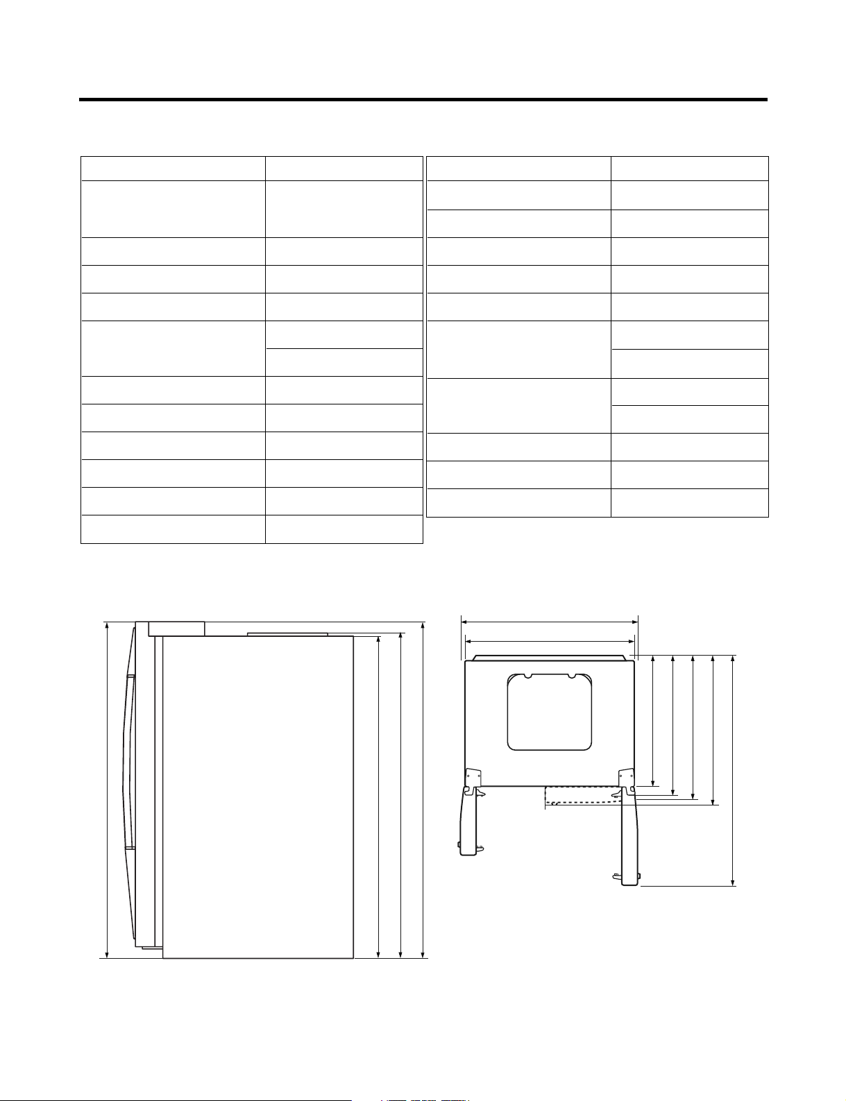
SPECIFICATIONS
724 mm (28
1
/
2
in.)
1004 mm (391/2 in.)
908 mm (39
11
/16 in.)
779 mm (30
5
/
8
in.)
829 mm (32
5
/
8
in.)
897 mm (35
5
/
16
in.)
1261 mm (49
5
/
8
in.)
1741.5 mm (68
1
/
2
in.)
1746.5 mm (68
3
/
4
in.)
1771 mm (69
11
/
16
in.)
1771 mm (69
11
/
16
in.)
1. Ref No. : GR-L267BV(T,S)PA
ITEMS SPECIFICATIONS
DIMENSIONS 908 X 896 X 1771 mm
W
X D X
H (35
NET WEIGHT 149 kg (328.5 lbs.)
COOLING SYSTEM Fan Cooling
TEMPERATURE CONTROL Micom Control
DEFROSTING SYSTEM Full Automatic
INSULATION Cyclo-Pentane
COMPRESSOR PTC Starting Type
EVAPORATOR Fin Tube Type
CONDENSER Wire Condenser
REFRIGERANT R134a (185g) (6
LUBRICATING OIL FREOL @10G (320 cc)
11
/16X355/16X6911/16 in.)
Heater Defrost
1
/2 oz.)
ITEMS SPECIFICATIONS
DRIER MOLECULAR SIEVE XH-7
CAPILLARY TUBE ID Ø0.83
FIRST DEFROST 4 - 5 Hours
DEFROST CYCLE 13 - 15 Hours
DEFROSTING DEVICE Heater, Sheath
ANTI-SWEAT HEATER Dispenser Duct Door Heater
Dispenser Heater
ANTI-FREEZING HEATER Water Tank Heater
Damper Heater
FREEZER LAMP 40W (1 EA)
REFRIGERATOR LAMP 40W (4 EA)
DISPENSER LAMP 15W (1 EA)
Front View Top View
- 4 -
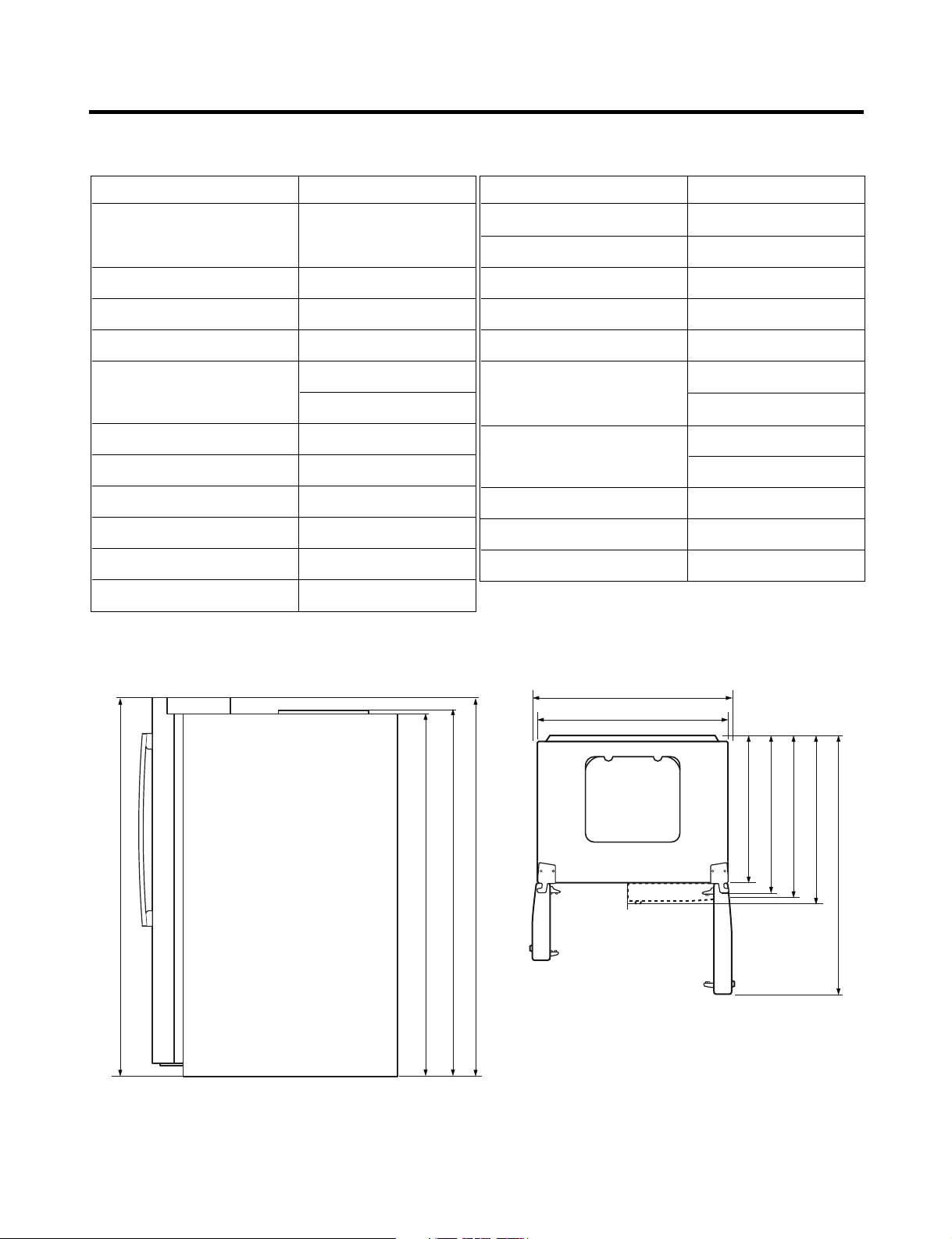
SPECIFICATIONS
2. Ref No. : GR-L267BV(T)RA
ITEMS SPECIFICATIONS
DIMENSIONS 908 X 896 X 1771 mm
W
X D X
H (35
NET WEIGHT 149 kg (328.5 lbs.)
COOLING SYSTEM Fan Cooling
TEMPERATURE CONTROL Micom Control
DEFROSTING SYSTEM Full Automatic
INSULATION Cyclo-Pentane
COMPRESSOR PTC Starting Type
EVAPORATOR Fin Tube Type
CONDENSER Wire Condenser
REFRIGERANT R134a (185g) (6
LUBRICATING OIL FREOL @10G (320 cc)
11
/16X355/16X6911/16 in.)
Heater Defrost
1
/2 oz.)
ITEMS SPECIFICATIONS
DRIER MOLECULAR SIEVE XH-7
CAPILLARY TUBE ID Ø0.83
FIRST DEFROST 4 - 5 Hours
DEFROST CYCLE 13 - 15 Hours
DEFROSTING DEVICE Heater, Sheath
ANTI-SWEAT HEATER Dispenser Duct Door Heater
Dispenser Heater
ANTI-FREEZING HEATER Water Tank Heater
Damper Heater
FREEZER LAMP 40W (1 EA)
REFRIGERATOR LAMP 40W (4 EA)
DISPENSER LAMP 15W (1 EA)
in.)
16
/
11
1771 mm (69
1004 mm (391/2 in.)
11
908 mm (39
in.)
in.)
2
/
1
1741.5 mm (68
Front View Top View
in.)
4
/
16
3
/
11
1771 mm (69
1746.5 mm (68
/16 in.)
in.)
in.)
in.)
2
8
8
/
/
1
/
5
5
724 mm (28
779 mm (30
829 mm (32
in.)
in.)
8
/
16
5
/
5
897 mm (35
1261 mm (49
- 5 -
SPECIFICATIONS
3. Ref No. : GR-L267BV(T)R
ITEMS SPECIFICATIONS
DIMENSIONS 908 X 896 X 1771 mm
11
5
W
X
D X H (35
/16
X
35
/16
11
/16
X
69
in.)
NET WEIGHT 149 kg (328.5 lbs.)
COOLING SYSTEM Fan Cooling
TEMPERATURE CONTROL Micom Control
DEFROSTING SYSTEM Full Automatic
Heater Defrost
INSULATION Cyclo-Pentane
COMPRESSOR PTC Starting Type
EVAPORATOR Fin Tube Type
CONDENSER Wire Condenser
REFRIGERANT R134a (185g) (6
1
/2 oz.)
LUBRICATING OIL FREOL @10G (320 cc)
ITEMS SPECIFICATIONS
DRIER MOLECULAR SIEVE XH-7
CAPILLARY TUBE ID Ø0.83
FIRST DEFROST 4 - 5 Hours
DEFROST CYCLE 13 - 15 Hours
DEFROSTING DEVICE Heater, Sheath
ANTI-SWEAT HEATER Dispenser Duct Door Heater
Dispenser Heater
ANTI-FREEZING HEATER Water Tank Heater
Damper Heater
FREEZER LAMP 40W (1 EA)
REFRIGERATOR LAMP 40W (3 EA)
DISPENSER LAMP 15W (1 EA)
in.)
16
/
11
1771 mm (69
1004 mm (391/2 in.)
11
908 mm (39
in.)
in.)
2
/
1
1741.5 mm (68
Front View Top View
in.)
4
/
16
3
/
11
1771 mm (69
1746.5 mm (68
/16 in.)
in.)
in.)
in.)
2
8
8
/
/
1
/
5
5
724 mm (28
779 mm (30
829 mm (32
in.)
in.)
8
8
/
/
5
1
892 mm (35
1261 mm (49
- 6 -
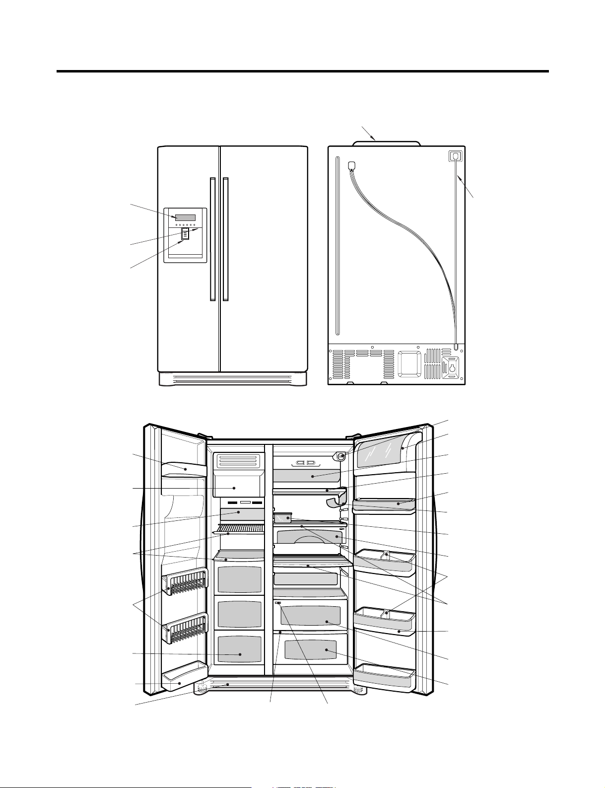
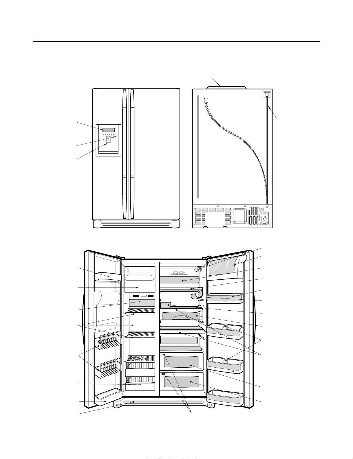
PARTS IDENTIFICATION
Frame Display
Dispenser Lamp
Ice & Water
Dispenser Button
PWB Cover
Water Tubes
Humidity Switch
Lamp
Shelf
Snack Drawer
Vegetable Drawer
OptiChill
Door Rack
Shelf
Grab and Go
Wine Holder
Lamp
Lower Cover
Dairy Product Corner
Door Rack
Drawer
(Wire/Plastic)
Freezer
Compartment
Refrigerator
Compartment
Automatic
Icemaker
Door Rack
Shelf
Bottle Guide
OptiChill Display
Water Filter
Door Rack
Egg Box
1. Ref No. : GR-L267BV(T,S)PA
- 7 -
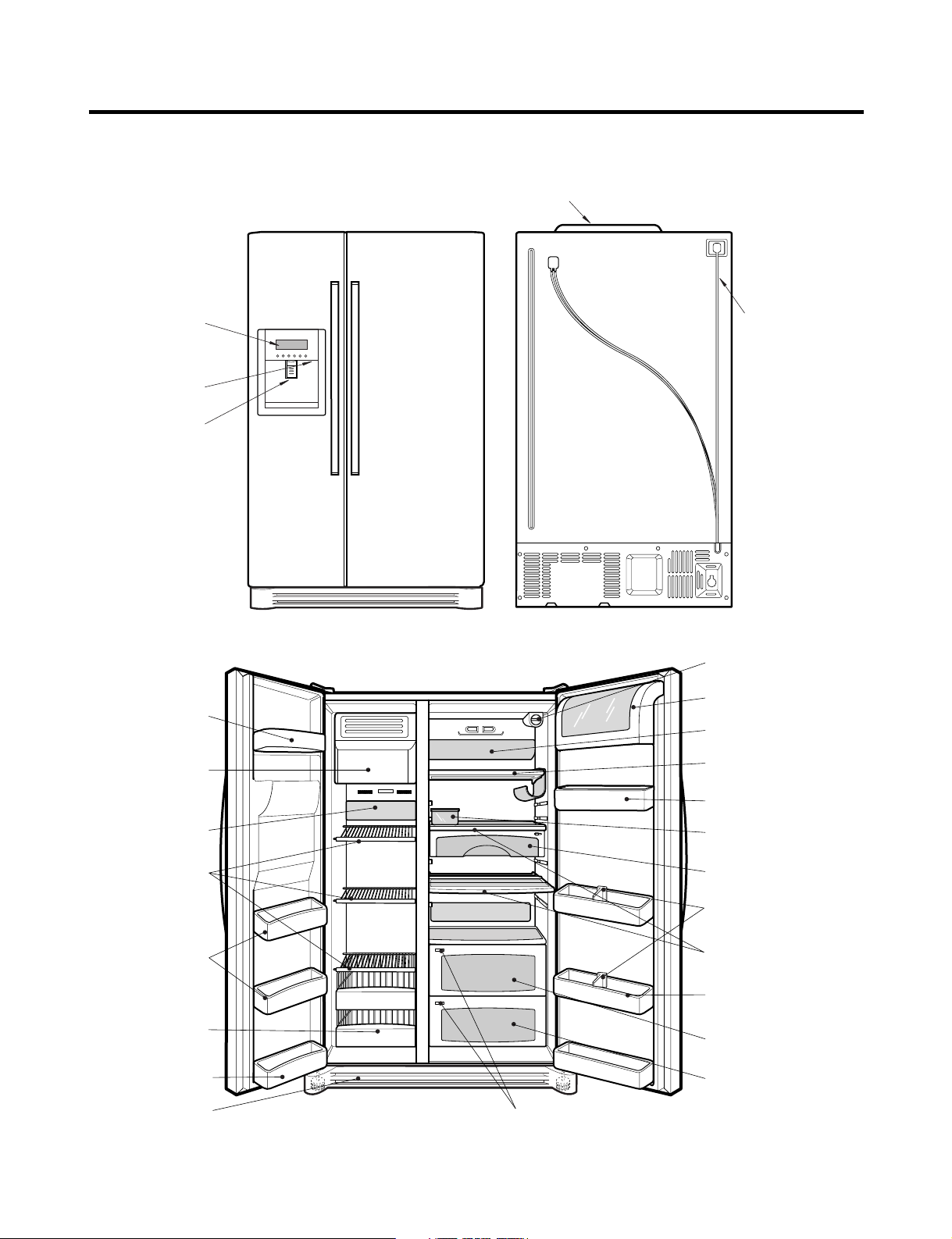
PARTS IDENTIFICATION
Frame Display
Dispenser Lamp
Ice & Water
Dispenser Button
PWB Cover
Water Tubes
Freezer
Compartment
Refrigerator
Compartment
Humidity Switch
Lamp
Shelf
Snack Drawer
Vegetable Drawer
Vegetable Drawer
/Meat Drawer
Door Rack
Shelf
Door Rack
Wine Holder
Lamp
Lower Cover
Dairy Product Corner
Door Rack
Drawer
(Wire/Plastic)
Automatic
Icemaker
Door Rack
Shelf
Bottle Guide
Door Rack
Water Filter
Egg Box
2. Ref No. : GR-L267BV(T)RA
- 8 -
PARTS IDENTIFICATION
Frame Display
Dispenser Lamp
Ice & Water
Dispenser Button
PWB Cover
Water Tubes
Lamp
Shelf
Snack Drawer
Vegetable Drawer
Vegetable Drawer
/Meat Drawer
Door Rack
Shelf
Door Rack
Lamp
Lower Cover
Dairy Product Corner
Door Rack
Drawer
(Wire/Plastic)
Freezer
Compartment
Refrigerator
Compartment
Automatic
Icemaker
Door Rack
Shelf
Door Rack
Water Filter
Humidity Switch
Bottle Guide
Egg Box
3. Ref No. : GR-L267BV(T)R
- 9 -
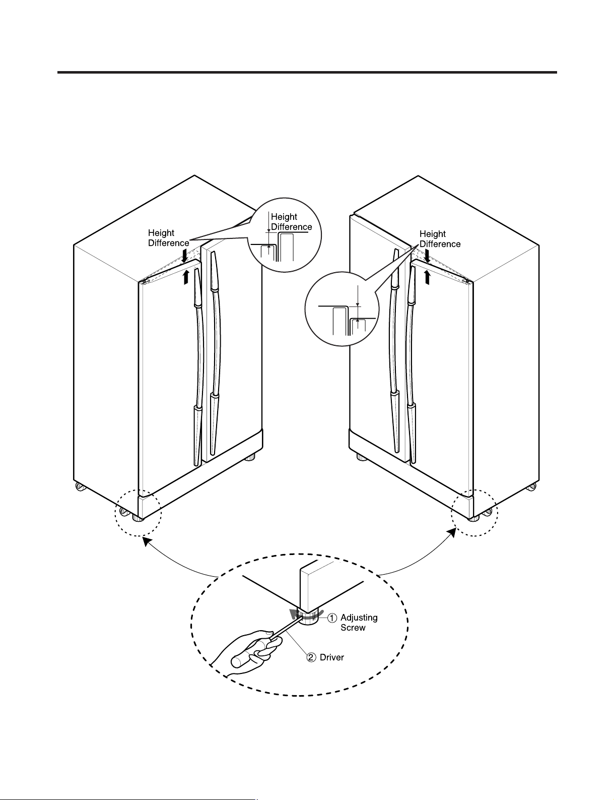
HOW TO INSTALL REFRIGERATOR
Adjusting
Screw
Driver
Height
Difference
Height
Difference
Height
Difference
Height
Difference
1
2
1. How to Adjust Door Height of Refrigerator
■ Make the refrigerator level first. (If the refrigerator is not installed on a flat floor, the height of freezer and refrigerator
door may not be the same.)
1. If the freezer door is lower than the refrigerator
door:
2. If the freezer door is higher than the refrigerator
door:
Insert a driver into the groove if the adjusting
screw and turn in the direction of the arrow (clockwise)
until the refrigerator is level.
- 10 -
Insert a driver into the groove if the adjusting
screw and turn in the direction of the arrow (clockwise)
until the refrigerator is level.
HOW TO INSTALL REFRIGERATOR
2. Filter
Replace the filter when the indicator light comes on or the
performance of the icemker or water dispenser decreases
noticeably.
After changing the water filter cartridge, reset the water
filter status display and indicator light by pressing and
holding the BUTTON for 3 seconds.(page 18)
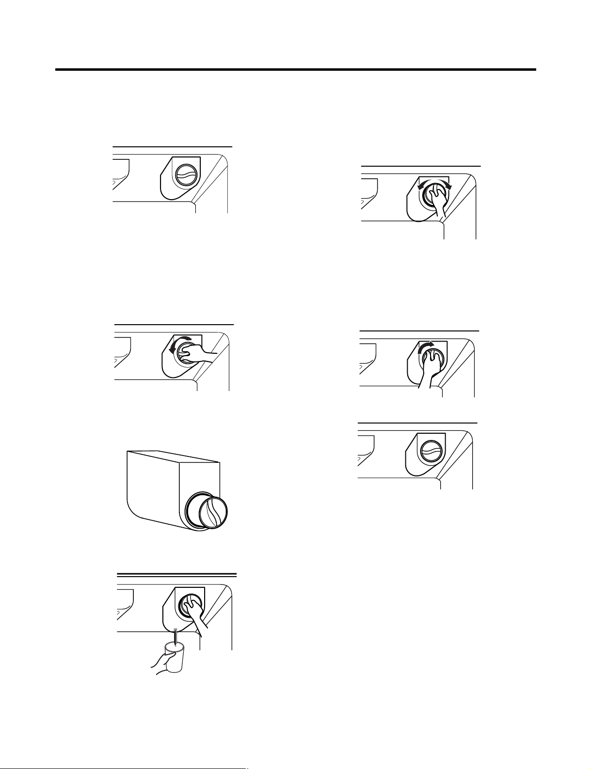
1. Remove the old cartridge.
Twist the knob of the cartridge counter clockwise.
2. Replace with a new cartridge.
Take the new cartridge out of its packaging and remove
protective cover from the o-rings.
With cartridge knob in the vertical position, push the new
filter cartridge into the cover until it stops.
If you can’t turn the filter from side to side, it isn’t fully
inserted. Push it in firmly and twist it into place. You will
hear the snap when it clicks into place.
Using the handle, twist the cartridge clockwise about 1/4
turn.
When the cartridge is removed, you will feel it click .
Pull out the cartridge.
NOTE: There will be some water(25cc) in the filter
cartridge. Some spilling may occur. Catch it in a
bowl or towel.
3. Flush the Water System After Replacing Filter Dispense
water through the water dispenser for 3 minutes to
purge the system.
There may be a little air in the line, causing noise or
hissing. Run the water at the dispenser until the hissing
stops to purge the air from the system.
NOTE: - To purchase replacement water filter cartridges,
visit your local appliance dealer or part distributor.
- You can also visit our website :
www.lgappliances.com or call 1-877-714-7481.
- 11 -
HOW TO INSTALL REFRIGERATOR
2
1
Test Switch
Confirm the amount
of water
Ice maker
Too much
Too little
Optimum level
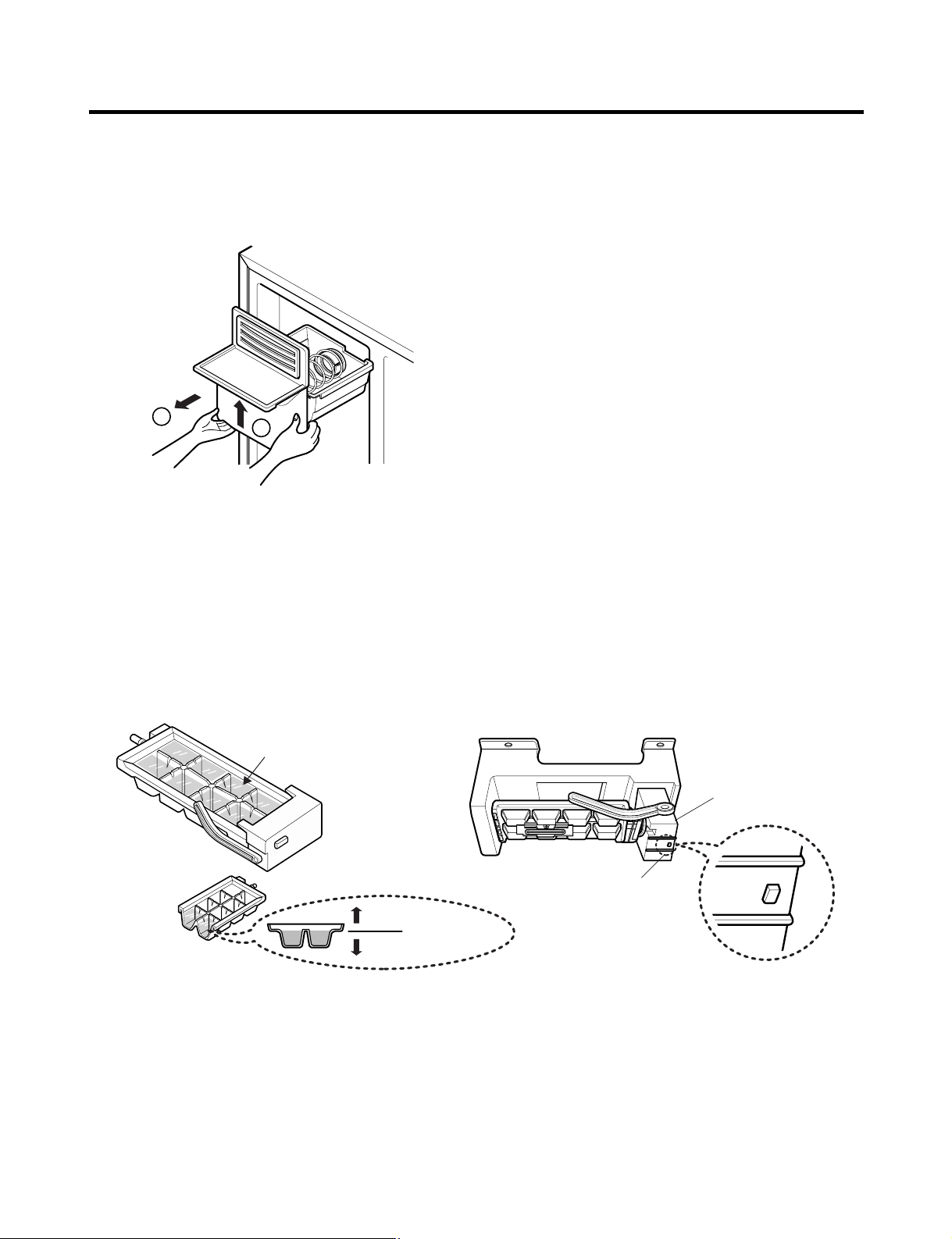
3. How to Control the Amount of Water Supplied to Icemaker.
3-1. Confirm the amount of water supplied to the icemaker.
1. Pull out the ice bin shelf in the upper part of the freezer compartment.
Caution : • Do not put hands or tools into the chute to confirm
the operation of geared motor.
It may damage the refrigerator or hurt your hands.
2. Apply electricity after connecting water pipe.
1) Press test switch under the icemaker for two seconds as shown below.
2) The bell rings(ding~dong) and ice tray rotates and water comes out from the icemaker water tube.
3) The water shall be supplied two or three times into the tray. The amount of water supplied for each time is small.
Put a water container under the ice tray and press test switch.
4) When ice tray rotates, the water in it will spill. Collect the spilt water and throw away into the sink.
5) When ice tray has finished rotation, water comes out from the water tube. Confirm the amounts of water in the ice tray.
(refer to fig. The optimum amount of water is 110cc)
* It is acceptable if the adjusted level of water is a bit smaller than optimum level.
- 12 -
HOW TO INSTALL REFRIGERATOR
(+) Driver
1
ON
Switch ON
Switch OFF
23
Confirm the amount
of water
Optimum level
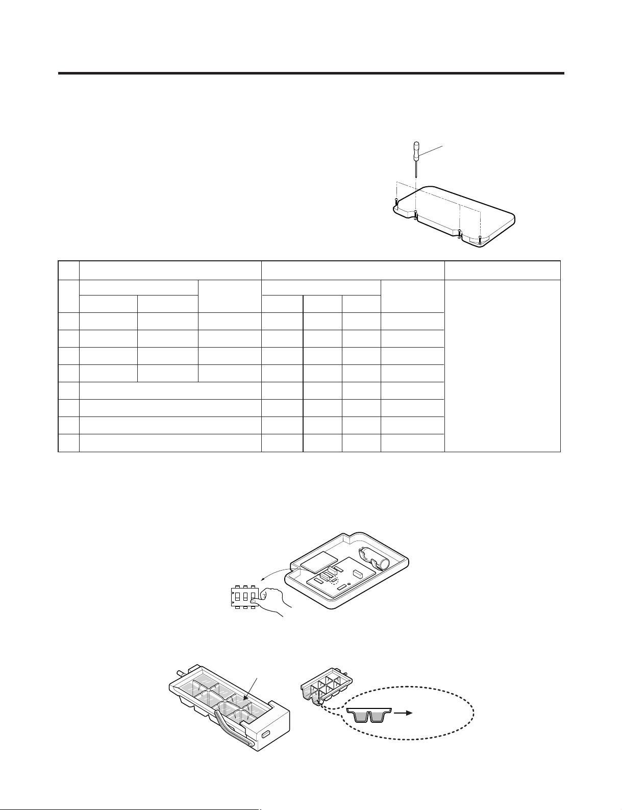
3-2. Control the amount of water supplied to the icemaker.
Caution : • Please unplug the power cord from the wall outlet and wait for more than three minutes before disconnecting
PWB cover as 310V is applied in the control panel.
1. Disconnect PWB cover from the upper part of the refrigerator.
2. Adjust the amount of water supplied by using DIP switch.
■ Water Supplying Time Control Option
REMARKS
supplied depends on DIP
switch setting conditions
and water pressure as it
is a direct tap water
connection type. (the
water supplied is
generally 80 cc to 120 cc)
PWB.
No
1
2
3
4
5
6
7
8
GR-L267BV(T)R GR-L267BV(T)RA, GR-L267BV(T,S)PA
DIP SWITCH SETTING
S1 S2
OFF OFF 6.5 SEC
ON OFF 5.5 SEC
OFF ON 7.5 SEC
ON ON 8.5 SEC
WATER
SUPPLY TIME
DIP SWITCH SETTING
S1 S2 S3
OFF OFF OFF 6.5 SEC
ON OFF OFF 5.5 SEC
OFF ON OFF 6 SEC
ON ON OFF 7 SEC
OFF OFF ON 7.5 SEC
ON OFF ON 8 SEC
OFF ON ON 9 SEC
ON ON ON 10 SEC
WATER
SUPPLY TIME
* The quantity of water
* DIP switch is on the main
1) The water supplying time is set at five seconds when the refrigerator is delivered.
2) The amount of water supplied depends on the setting time and water pressure (city water pressure).
3) If ice cube is too small, increase the water supplying time. This happens when too small water is supplied into the ice tray.
4) If ice cube sticks together, decrease the water supplying time. This happens when too much water is supplied into the ice tray.
Caution : When adjusting the amount of water supplied, adjust step by step. Otherwise the water may spill over.
3. When adjustment of control switch for the amount of water supplied is complete, check the level of water in the ice tray.
- 13 -
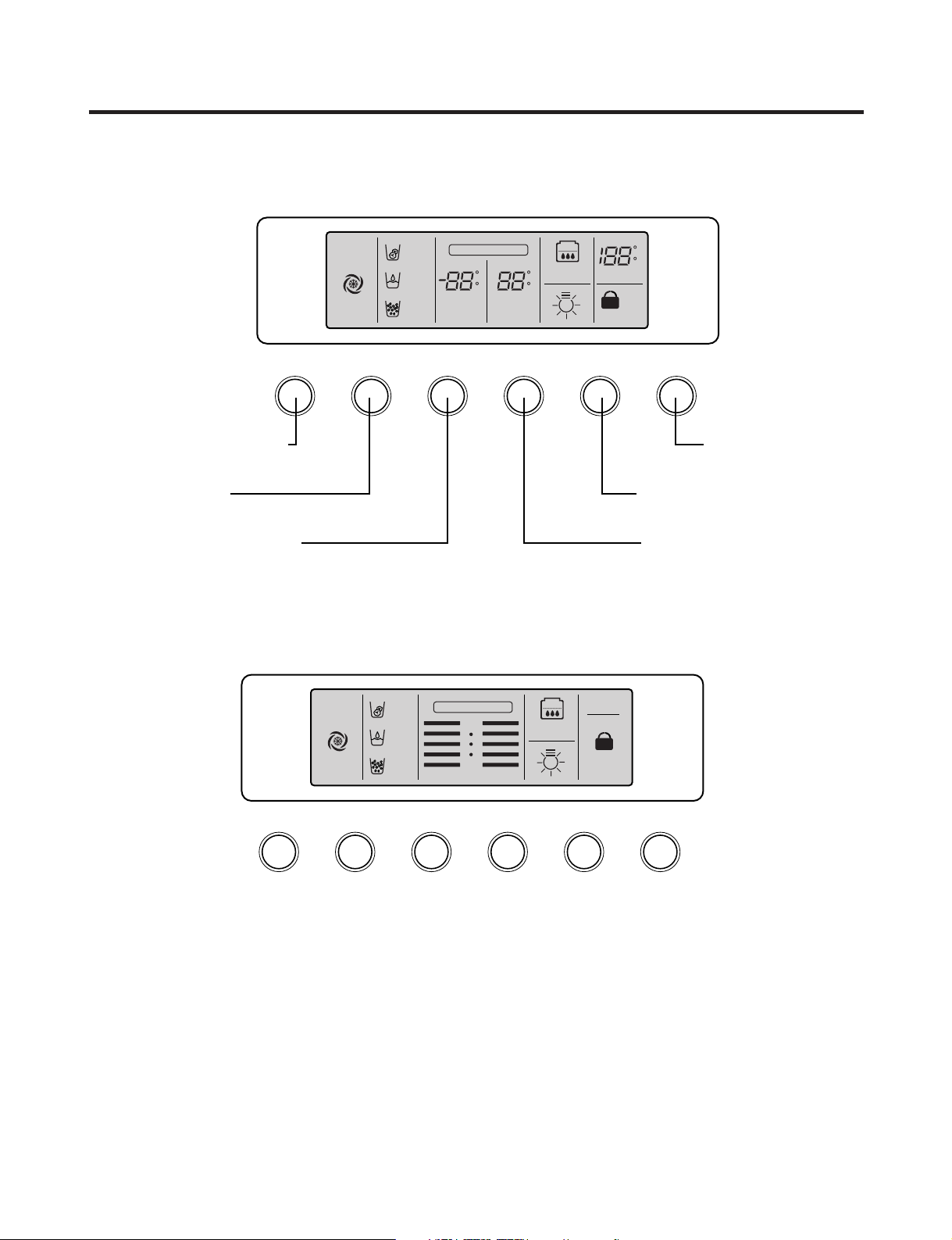
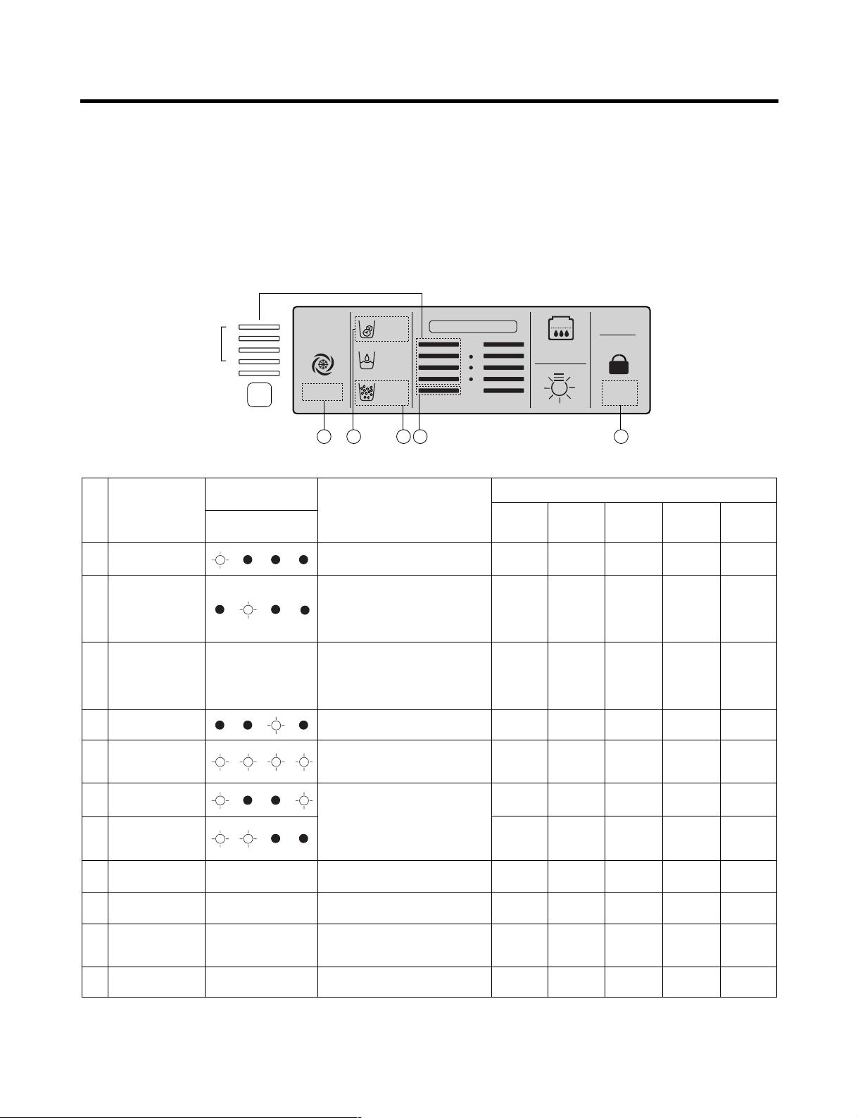
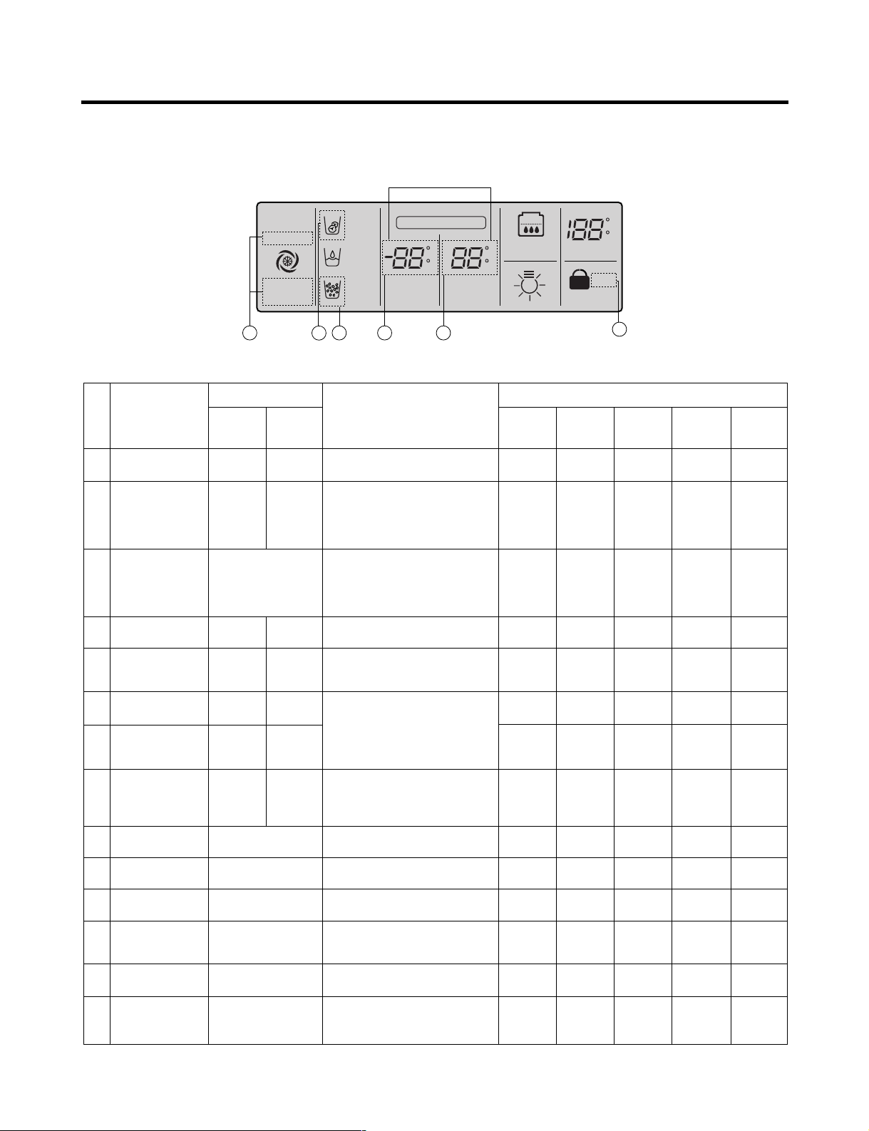
MICOM FUNCTION
EXPRESS/JET FRZ DISPENSER FREEZER REFRIGERATOR FILTER/LIGHT LOCK
Dispenser selection
button
Express Freezer/Jet Freezer
function selection button
Dispenser and button
Lock button
Dispenser Lamp On/Off button/
Filter status display RESET button
Temperature adjustment button
for refrigerator compartment
Temperature adjustment button
for freezer compartment
EXPRESS
FRZ
(EXPRESS)
ON
(JET)
CUBE
ROOM TEMPERATURE
LOCK
DISPENSER & BUTTON
F
WATER
CRUSH
C
3 SECS
DIGITAL CONTROL
FRZ TEMP
F
C
F
C
REF TEMP
FILTER RESET
HOLD 3SECS
FILTER
EXPRESS DISPENSER FREEZER
REFRIGERATOR
FILTER RESET/LIGHT
LOCK
EXPRESS
FRZ
ON
CUBE
LOCK
DISPENSER
BUTTON
WATER
CRUSH
3 SECS
DIGITAL CONTROL
FRZ TEMP REF TEMP
COLDEST
COLD
FILTER RESET
HOLD 3SECS
FILTER
1. Monitor Panel
1-1. GR-L267BV(T)RA, GR-L267BV(T, S)PA
1-2. GR-L267BV(T)R
- 14 -
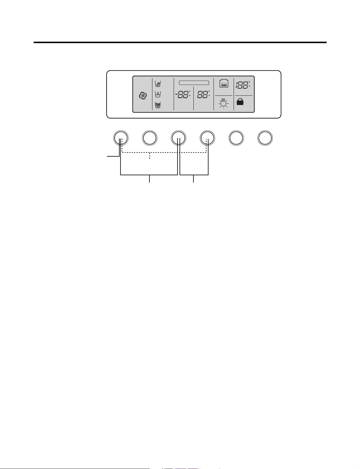
MICOM FUNCTION
EXPRESS/JET FRZ DISPENSER FREEZER REFRIGERATOR FILTER/LIGHT LOCK
Display Power
saving Mode
Exhibition Mode
EXPRESS
FRZ
(EXPRESS)
ON
(JET)
CUBE
ROOM TEMPERATURE
LOCK
DISPENSER & BUTTON
F
WATER
CRUSH
C
3 SECS
DIGITAL CONTROL
FRZ TEMP
F
C
F
C
REF TEMP
FILTER RESET
HOLD 3SECS
FILTER
Change Display Degree from
Fahrenheit to Centigrade Mode
Buzzer sound
mute Mode
1-3. Display Second Function
1. Buzzer sound mute Mode
The buzzer sound is set to OFF.
It activates by sounding the recognition sound of “Ding~” after pressing and holding “Express FRZ” button more than 5
seconds. It inactivates when resetting the mode power.
2. Display Power saving Mode
It places display in standby mode until door is opened.
Press “Freezer” and “Express FRZ” buttons simultaneously to turn all leds become ON and then OFF with the recognition
sound of “Ding~” after 5 seconds. (Be sure not to press only one button to work.)
Once the mode activates, the display is always OFF. Until door is opened or display button is pressed. When 30 seconds
has elapsed after closing door or pressing button, the display turns OFF. To deactivate this mode is same as the
activation methods. The mode inactivates when resetting the power.
3. Change Display Degree to Centigrade Mode from Fahrenheit Mode
To change temperature display from Fahrenheit to Celsius press and hold “FREEZER” and “REFRIGERATOR” buttons
simultaneously for more than 5 seconds. Do the same to convert back to Celsius.
4. Exhibition Mode
This function is available when exhibiting a refrigerator in the shopping moll.
Function is inserted with recognition sound “Ding ~” if pressing both the “Freezer” button and the “REFRIGERATOR”
button at the same time for more than 5 seconds. If function is inserted, all basic refreezing functions at the R/F room and
the Storage room (COMP, F-FAN, C-FAN) turns off and the display normally operates. However, the dispenser function
normally operates.
The DEMO stops if pressing the button during DISPLAY DEMO, DEMO stops and the display normally operates but
performs DEMO operation again if not pressing the button again for more than 30 seconds (DEMO: Display scenario
when using the display).
Release method is same as input method.
The mode is released if power is reset.
- 15 -
MICOM FUNCTION
2. Description of Function
2-1-1. Function of Temperature Selection
Division Power Initially On 1st Press 2st Press 3th Press 4th Press
Setting
temperature
Temperature
Control
Freezer Control
Refrigeration
Control
* The temperature can vary ±3 °C depending on the load condition.
5
4
3
2
1
Medium Medium Max Max Min Medium Min
-2 °F -5 °F -8 °F7 °F1 °F
37 °F 34 °F 32 °F 46 °F 41 °F
5
4
3
2
1
5
4
3
2
1
5
4
3
2
1
5
4
3
2
1
❉ Whenever pressing button, setting is repeated in the order of (Medium) ➝ (Medium Max) ➝ (Max) ➝ (Min) ➝
(Medium Min).
• The actual inner temperature varies depending on the food status, as the indicated setting temperature is a target
temperature, not actual temperature within refrigerator.
• Refrigeration function is weak in the initial time. Please adjust temperature as above after using refrigerator for minimum
2~3 days.
• Freezer Notch is fixed “Medium Max” unconcerned with display Notch during ICE Making Control Mode and Ice Maker
Stop switch is selected with “ON”.
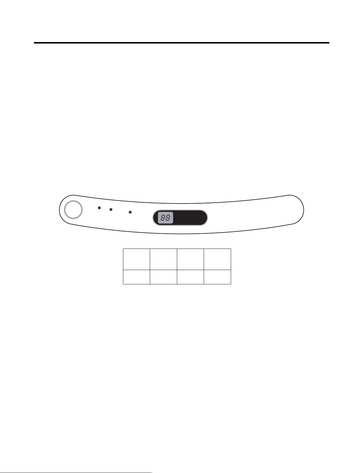
2-1-2. Outside temperature display function
1. Outside temperature sensor at the right Hinge Cover - U of refrigerator senses ambient temperature and displays the
outside temperature in the upper of “ROOM TEMP” text on the display part.
2. Ambient temperature is displayed up to 16°F ~ 120°F and displayed as “Lo” for less than 15°F and as “HI” for more than
121°F. If the ambient temperature sensor fails, it is displayed as “Er”.
3. Since display temperature of outside temperature is temperature sensed by the ambient sensor in the hinge U of the
refrigerator room, it may differ from the outside temperature display of other household electrical appliances.
- 16 -
MICOM FUNCTION
LOCK
DISPENSER & BUTTON
3 SECS
LOCK
DISPENSER & BUTTON
3 SECS
LOCK CONTROL
Ex) Select
LOCK
Ex) Select
LOCK again
In initial Power On
/ Filter RESET
Replace indicator
light on
Classification
Filter Status
Display
FILTER RESET
HOLD 3SECS
FILTER
FILTER RESET
HOLD 3SECS
FILTER
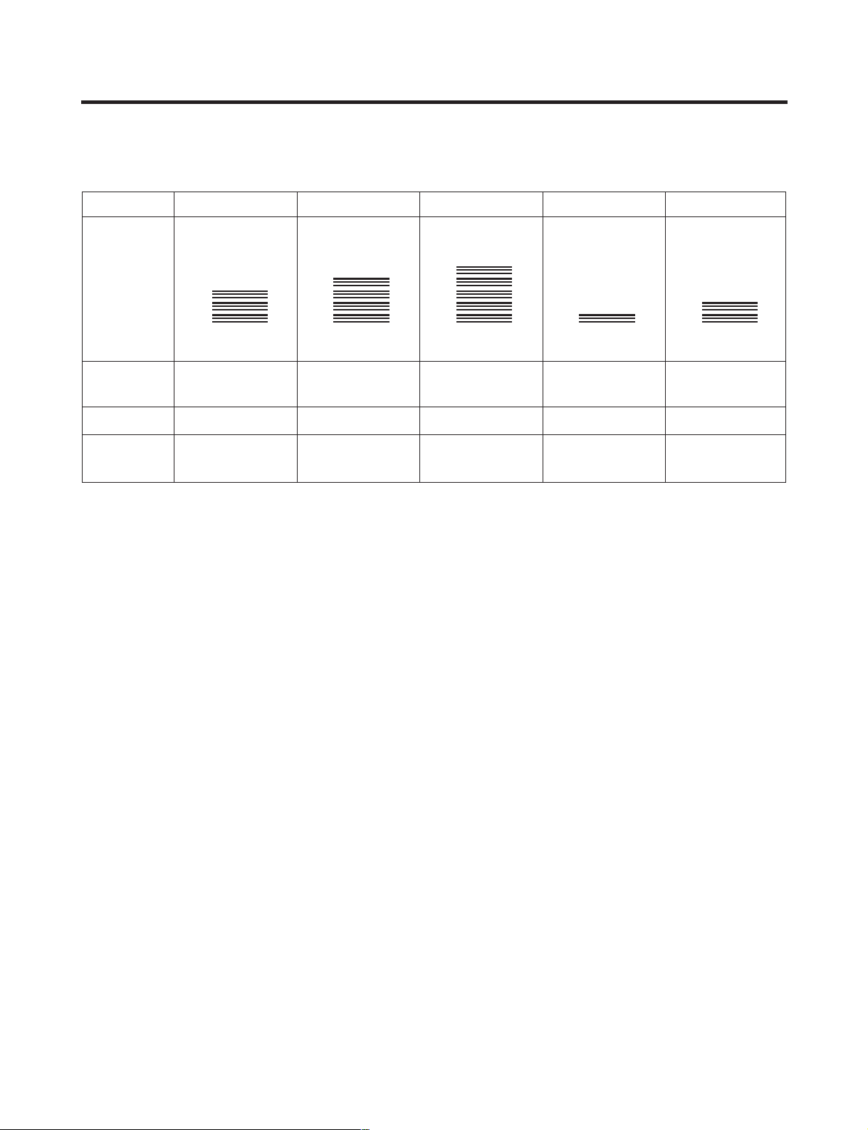
2-1-3. Lock function (dispenser and display button lock)
1. In power application of refrigerator, the “LOCK” text is turned off at the right side of lock graphic of display with the lock
replease status.
2. If desiring to lock the dislay the dispenser and control panel, push on the LOCK button more than 3 seconds. LOCK text
is turned on at the right side of lock graphic of display with lock status.
3. The buzzer sound and control panel and dispenser function is not performed even if pressing display button other than
lock key in the lock status.
4. If desiring to release the lock status and pressing the lock button more than 3 seconds. “LOCK” text is turned off at the
right side of lock graphic of display with the lock release status.
LED
2-1-4. Filter condition display function
1. There is a replacement indicator light for the water filter cartridge on the dispenser.
2. Water filter needs replacement once six months.
3. Water filter light and “FILTER RESET HOLD 3SECS” text turn on to tell you need to replace the filter soon.
4. After replace the filter, press and hold the lock button more than 3seconds.
Then water filter light and “FILTER RESET HOLD 3SECS” text turn off with reset status.
- 17 -
MICOM FUNCTION
DISPENSER
LED
CUBE
WATER
CRUSH
Pressing
Switch
LED (GR-L267BV(T,S)PA)
LED (GR-L267BV(T)R, GR-L267BV(T)RA)
EXPRESS/JET FRZ
EXPRESS/JET FRZ
EXPRESS
FRZ
EXPRESS EXPRESS EXPRESS
ON
EXPRESS
FRZ
ON
JET JET JET
Dispenser Iight ON/OFF
LED
DISPENSER
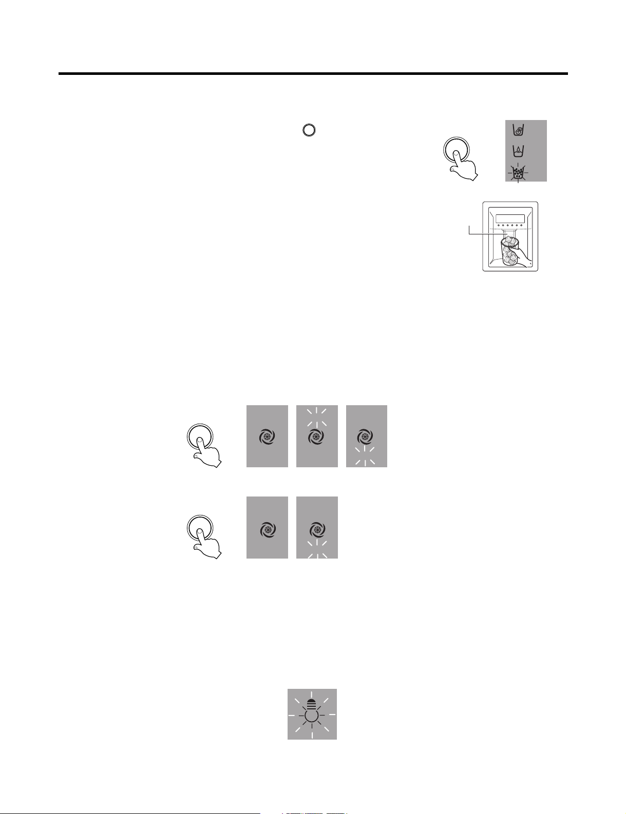
2-2. Dispenser use selection
You can select water or ice.
❉ Please select water, slice ice and square ice by pressing button as you
desire.
❉ Please press the push button lightly by catching and pushing in cup.
• Each graphic is indicated for the selected function.
• “Tak!” sounds if 5 seconds pass after ice comes out.
It is sound that the outlet of ice is closed.
REFERENCE : Please wait for 2-3 seconds in order to take final ice slices or drops
of water when taking out cup from the pressing switches after
taking ice or water.
2-3. Express freezing/JET freezing selection
Please select this function for prompt freezer.
• Function is repeated following below whenever pressing EXPRESS/JET FRZ button.
• The arrow mark graphic remains at the On status after flickering 4 times when selecting Special Refrigeration “EXPRESS
FRZ” or “JET FRZ”.
• Expressing freezer or jet freezer function automatically turns off if a fixed time passes.
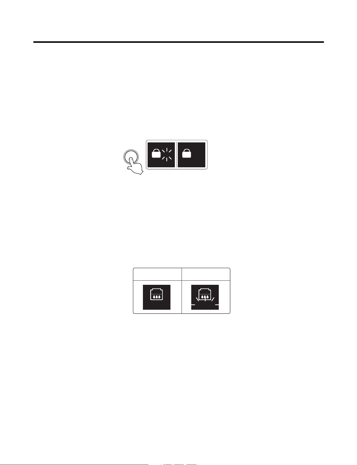
2-4. Dispenser Light
• Dispenser switch or dispenser light button turn the dispenser light in the dispenser on and off.
• The dispenser light Function is repeated following below whenever pressing “FILTER RESET/LIGHT” button.
• If dispenser light continuously turns on more than 7 minutes with dispenser light button, the dispenser light turns off
automatically by compulsion.
- 18 -

MICOM FUNCTION
2-5. Express freezing
1. Express freezing is function to improve cooling speed of the freezing room by consecutively operating compressors and
freezing room fan.
2. Express freezing is released if power failure occurs and then returns to the original status.
3. Temperature setting is not changed even if selecting the express freezing.
4. The change of temperature setting at the freezing room or the cold storage room is allowed with express freezing
selected and prrocessed.
5. The cold storage room operates the status currently set with Express freezing selected and procesed.
6. If selecting the Express freezing, the Express freezing function is released after continuously operating compressor and
freezing room fan.
7. If frost removal starting time is arrived during Express freezing, Express freezing operation is done only for the remaining
time after completion of frost removal when the Express freezing operation time passes 90 minutes. If passing 90
minutes, Express freezing operation is done only for 2 hours after completion of frost removal.
8. If pressing Express freezing button during frost removal, the Express freezing LCD or LED is turned on but if pressing the
Express freezing, compressor operates after the remaining time has passed.
9. If selection Express freezing within 7 minutes (delay for 7 minutes of compressor) after the compressor stops,
compressor operates after the remaining time has passed.
10. The freezing room fan motor operates at the high speed of RPM during operation of Express freezing.
2-6. Jet Freezing (GR-L267BV(T,S)PA Model)
1. Jet freezing is function to improve cooling speed of the Jet Freezing Room in the freezer room by consecutively operating
compressor and Jet freezing box fan motor.
2. Jet freezing is released if power failure occurs and then returns to the original status.
3. Display temperature setting is not changed even if selectig the jet freezing.
4. If Jet Freezing is selected, comp (after comp delay time passes) and fan motor in freezer room will be on. The
temperature in refrigerator room will be drop and fan motor will be off for certain time, and then the fan motor in Jet
Freezing box will be on for maximum 2 hours.
After that, terminate the Jet Freezing function and display as off status.
5. To prevent from being frozen, the fan motor of jet freezing box will be on for 10 sec. by every 1hour when it doesn’t
operate.
6. The fan motor of jet freezing box will not be detected as a failure. (dc 12v operation)
7. When checking the jet freezing function, the fan motor of jet freezing box to be for 1 min. In case of pressing the freezer
adjust button and express freezing button over 1 sec.
- 19 -
MICOM FUNCTION
°F / SET TEMP
/ TIME REMAINING
MIN
FRUIT
VEGE
CHILED
ROOM
PARTIAL
FREEZING
SELECT
HR
2-7. OptiChill Function (GR-L267BV(T,S)PA Model)
1. The OptiChill is positioned at the bottom of fresh food room separately and allow a user to select and adjust a desired
temperature according to kinds of food such as meat, fish, vegetables and fruits and so on. The selected temperature to
any kinds of food let user to keep their food longer.
2. OptiChill comprises of OptiChill sensor at the rear of OptiChill and a damper between OptiChill and freezer room and a
temperature adjusting display at the top of it.
3. When powered on, the initial NOTCH of OptiChill display will be on “FRUIT VEGE”.
If only R-DOOR is OPENED, OptiChill LED will be ON.
4. Every time pressing the button, the LED shows “FRUIT VEGE”(39°F) → “CHILED ROOM”(30°F) → “PARTIAL FREEZING
(27°F)” → “FRUIT VEGE”(39°F) in orders and also shows a target temperature to be controlled at the same time, then the
NOTCH will be changed relatively.
5. The OptiChill sensor detects a desired temperature at micom, and if the temperature is satisfied, the OptiChill damper will
be closed and if the temperature is unsatisfied, the OptiChill damper will be opened and then the temperature will be
cooled.
6. If the OptiChill damper doesn’t operate for 1 hour, it will be physically operated for seconds to prevent from being frozen.
NOTCH
Partial
Freezing
Chilled
Room
Fruit
VEGE
Display 27°F30°F39°F
- 20 -
MICOM FUNCTION
Doors of freezing /
cold storage room
or home bar
BUZZER
Closing
Opening
Within
a minute
A minute
30
seconds30seconds30seconds
Opening
Closing Closing
3 Times 3 Times 3 Times 3 Times
2-8. Control of variable type of freezing fan
1. To increase cooling speed and load response speed, MICOM variably controls freezing room fan motor at the high speed
of RPM and standard RPM.
2. MICOM only operates in the input of initial power or express freezing operation or load response operation for the high
speed of RPM and operates in the standard RPM in other general operation.
3. If opening doors of freezing / cold storage room or home bar while fan motor in the freezing room operates, the freezing
room fan motor normally operates (If being operated in the high speed of RPM, it converts operation to the standard
RPM). However, if opening doors of freezing room or home bar, the freezing room fan motor stops.
4. As for monitoring of BLDC fan motor error in the freezing room, MICOM immediately stops the fan motor by determining
that the BLDC fan motor is locked or poor if there would be position signal for more than 115 seconds at the BLDC motor.
Then it displays failure (refer to failure diagnosis function table) at the display part of refrigerator, the BLDC motor doesn’t
operate more. If you want to operate the BLDC motor, turn off and on power resource.
2-9. Control of cooling fan motor
1. The cooling fan motor performs ON/OFF control by linking with the COMP.
2. It controls at the single RPM without varying RPM.
3. Failure sensing method is same as in fan motor of freezing fan motor (refer to failure diagnosis function table for failure
display).
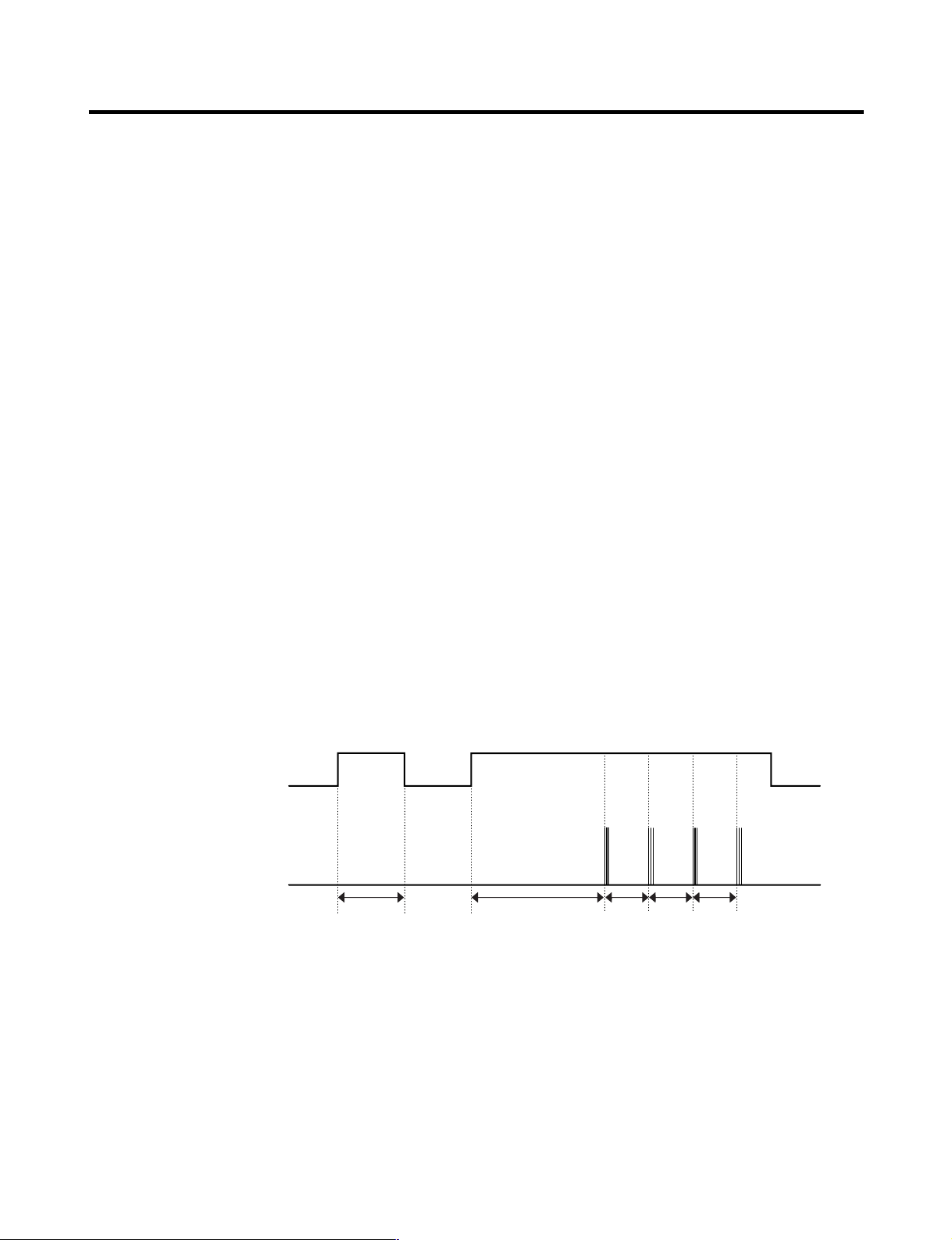
2-10. Door opening alarm
1. Buzzer generates alarm sound if doors are not closed even when more than a minute consecutively has passed with
doors of freezing / cold storage room or home bar opened.
2. Buzzer rings three times in the interval of 0.5 second after the first one-minute has passed after doors are opened and
then repeats three times of On/Off alarm in the cycle of every 30 seconds.
3. If all the doors of freezing / cold storage room or home bar are closed during door open alarm, alarm is immediately
released.
2-11. Ringing of button selection buzzer
1. If pressing the front display button, “Ding ~ “ sound rings.
- 21 -

MICOM FUNCTION
2-12. Ringing of compulsory operation, compulsory frost removal buzzer
1. If pressing the test button in the main PCB, “Phi ~” sound rings.
2. In selecting compulsory operation, alarm sound is repeated and completed in the cycle of On for 0.2 second and Off for
1.8 second three times.
3. In selecting compulsory frost removal, alarm sound is repeated and completed in the cycle of On for 0.2 second , Off for
0.2 second, On for 0.2 second and Off for 1.4 second three times.
2-13. Frost removal function
1. Frost removal is performed whenever total operation time of compressor becomes 7 ~ 7.5 hour.
2. In providing initial power (or returning power failure), frost removal starts whenever total operation time of compressor
becomes 4 ~ 4.5 hour.
3. Frost removal is completed if temperature of a frost removal sensor becomes more than 5°C after starting frost removal.
Poor frost removal is not displaced if it does not arrive at 5°C even if two hours have passed after starting frost removal.
4. No removal is done if frost removal sensor becomes poor (snapping or short-circuit).
2-14. Refrigerator room lamp automatically off
• Refrigerator room lamp turn on and off by refrigerator door switch.
• If refrigerator room lamp continuously turns on more than 7 minutes, the refrigerator room lamp turns off automatically by
compulsion.
- 22 -
MICOM FUNCTION
POWER
ON
COMP
ON
F-FAN
&
C-FAN
ON
R-STEP
MOTOR
DAMPER
ON
OPTICHILL
STEP
DAMPER
MOTOR
ON
FROST
REMOVAL
HEATER
OFF
FROST
REMOVAL
HEATER
ON
DAMPER
&
DUCT DOOR
&
OPTICHILL
HEATER ON
DAMPER
&
DUCT DOOR
&
OPTICHILL
HEATER OFF
0.3
sec.
6.0
sec.
0.3
sec.
0.3
sec.
0.3
sec.
POWER
ON
0.3
sec.
PIPE
&
DISP'
HEATER
OFF
0.3
sec.
COMP
ON
0.3
sec.
F-FAN
&
C-FAN
ON
0.3
sec.
R-STEP
MOTOR
DAMPER
ON
0.3
sec.
OPTICHILL
STEP
DAMPER
MOTOR
ON
PIPE
&
DISP'
HEATER
ON
TEST
SWITCH
(PRESS
Once)
OTHER
LOAD
OFF
COMP
ON
F-FAN
&
C-FAN
ON
R-STEP
MOTOR
DAMPER
ON
OPTICHILL
STEP
DAMPER
MOTOR
CLOSE
TEST
SWITCH
(PRESS
2 Times)
COMP
OFF
F-FAN
&
C-FAN
OFF
FROST
REMOVAL
HEATER
ON
R-STEP
MOTOR
DAMPER
CLOSE
0.3
sec.
0.3
sec.
0.3
sec.
0.3
sec.
0.3
sec.
0.3
sec.
0.3
sec.
0.3
sec.
0.3
sec.
0.3
sec.
0.3
sec.
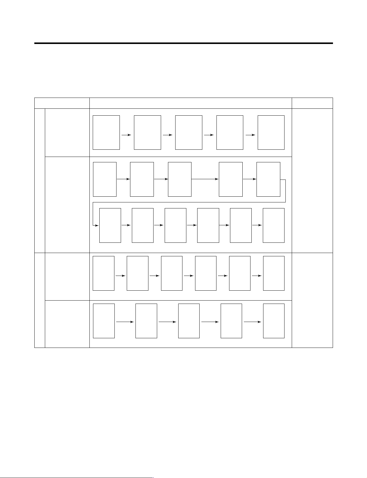
2-15. Sequential operation of built-in product
Built-in products such as compressor, frost removal heater, freezing room fan, Cooling Fan and step motor damper are
sequentially operated as follows for preventing noise and part damage occurred due to simultaneous operation of a lot of
parts in applying initial power and completing test.
Function Load Operation Sequence Remark
In applying Initial power TEST MODE
When temperature
of a frost removal
sensor becomes
more than 45°C
(In purchase,
movement)
When
temperature of a
frost removal
sensor becomes
less than 45°C
(In power failure,
service)
Test mode 1
(Compulsory
function)
Test mode 2
(Compulsory frost
removal)
If error occurs
during operation,
initial operation is
not done.
■
Sequence of
load operation
when closing
F-room and
R-room.
If pressing switch
once more in the
test mode 2 or
temperature of a
frost removal
sensor is more
than 5°C, it
immediately
returns to the test
mode for initial
operation
(COMP operates
after 7 minutes).
- 23 -
MICOM FUNCTION
EXPRESS
FRZ
ON
CUBE
LOCK
DISPENSER
BUTTON
WATER
CRUSH
3 SECS
DIGITAL CONTROL
FRZ TEMP REF TEMP
COLDEST
COLD
FILTER RESET
HOLD 3SECS
FILTER
C E F DG
FRZ
TEMP
Trouble Code
Index
Trouble Code
F4
F3
F2
F1
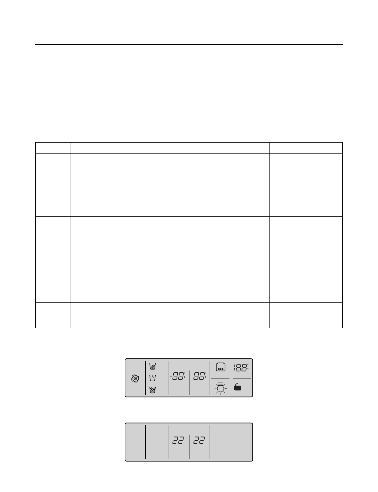
2-16. Failure Diagnosis Function
1. Failure diagnosis function is function to facilitate service when nonconforming matters affecting performance of product
during use of product.
2. In occurrence of failure, pressing the function adjustment button does not perform function.
3. If nonconforming matters occurred are released during display of failure code, MICOM returns to the original state (Reset).
4. Failure code is displayed on the display part of setting temperature for the freezing room and the display part of setting
temperature for the cold storage room of display, which are placed at the display part of a refrigerator. All the display
graphics other than a failure code are turned off.
(1) GR-L267BV(T)R Model
: On l : Off ˇ : Normal
No. Item
1
Abnormal
freezer sensor
2
Abnormal refrigerator
sensor 1 (R1)
(Upper part in the
refrigerator
compartment)
3
Abnormal refrigerator
sensor 2 (R2)
(Upper part in the
refrigerator
compartment)
Abnormal defrost
4
sensor
Failed defrosting
5
Abnormal freezing
6
BLDC motor
Abnormal cooling
7
BLDC motor
Abnormal
8
ambient sensor
Abnormal
9
ice-maker sensor
Abnormal
10
ice-maker unit
Abnormal W/T
11
sensor
Trouble Code Index
F1 F2 F3 F4
Normal display
(Note 1)
Normal display
(Note 1)
Normal display
(Note 1)
Normal display
(Note 1)
Normal display
(Note 1)
Contents of failure
Compressor
Freezer sensor short circuit
ON for 15minutes /
OFF for 15minutes
Refrigerator sensor1 short circuit
Refrigerator sensor2 short circuit
Abnormal short circuit
Defrost heater, temperature fuse short
circuit, unplugged connector(indicated
4 hour later after trouble)
Motor defect, hooked of lead wire
to fan, contact of structures with
fan, short or open of lead
wire(there is no signal of BLDC
motor more than 115 seconds in
operation of fan motor)
Ambient sensor short circuit
Ice-maker sensor short circuit
Faulty ice-maker unit morot or hall
ic, lead wire short circuit, faulty
motor driving circuit
Water Tank sensor short circuit
Product operation status in failure
Freezing
BLDC motor
Standard
Cooling
BLDC motor
●●
RPM
Standard
●●
●●
RPM
Standard
●●
●●
RPM
Standard
●●
●●
RPM
Standard
●●
●●
RPM
●●
●●
OFF
Standard
●●
OFF
RPM
●●
●●
●●
●●
●●
●●
●●
●●
●●
●●
●●
●●
Defrost
Heater
●●
●●
●●
No defrost
●●
●●
●●
●●
●●
●●
●●
Stepping
motor damper
●●
Full opening for
10 minutes/
Full closing for
15 minutes
●●
●●
●●
●●
●●
●●
●●
●●
●●
- 24 -
MICOM FUNCTION
Failure Code Indication Part
EXPRESS
FRZ
(EXPRESS)
ON
(JET)
CUBE
ROOM TEMPERATURE
LOCK
DISPENSER & BUTTON
F
WATER
CRUSH
C
3 SECS
DIGITAL CONTROL
FRZ TEMP
F
C
F
C
REF TEMP
FILTER RESET
HOLD 3SECS
FILTER
C F A B
E
D
(2) GR-L267BV(T)RA, GR-L267BV(T,S)PA Model
Failure code indication part
No. Item
1
Abnormal
freezer sensor
2
Abnormal refrigerator
sensor 1 (R1)
(Upper part in the
refrigerator
compartment)
3
Abnormal refrigerator
sensor 2 (R2)
(Middle part in the
refrigerator
compartment)
Abnormal defrost
4
sensor
Failed defrosting
5
Abnormal freezing
6
BLDC motor
Abnormal cooling
7
BLDC motor
Abnormal
8
communication
Abnormal
9
ambient sensor
Abnormal
10
Optichill sensor
Abnormal
11
ice-maker sensor
Abnormal
12
ice-maker unit
Abnormal
13
W/T sensor
Abnormal
14
Drive Micom
Communication
Freezer room
notch temperature
display
Er FS
Er rS
Normal display
Er dS
Er dH
Er FF
Er CF
Er CO
Normal display
Normal display
Normal display
Normal display
Normal display
Normal display
Refrigerator room
notch temperature
display
(Note 2)
(Note 2)
(Note 1)
(Note 1)
(Note 1)
(Note 1)
(Note 1)
Contents of failure
Freezer sensor short circuit
Refrigerator sensor1 short circuit
Refrigerator sensor2 short circuit
Abnormal short circuit
Defrost heater, temperature fuse short
circuit, unplugged connector(indicated
4 hour later after trouble)
Motor defect, hooked of lead wire
to fan, contact of structures with
fan, short or open of lead
wire(there is no signal of BLDC
motor more than 115 seconds in
operation of fan motor)
Short or open of lead wire
connecting between main PCB
and display PCB, transmission tr
and receiving part
Ambient sensor short circuit
Optichill sensor short circuit
Ice-maker sensor short circuit
Faulty ice-maker unit motor or hall
ic, lead wire short circuit, faulty
motor dirving circuit.
Water Tank Sensor short circuit
Abnormal of TR, Micom between
Set Micom and Drive Micom
(OptiChill Display)in MAIN PCB
Product operation status in failure
Compressor
ON for 15minutes /
OFF for 15minutes
●●
●●
●●
●●
●●
●●
●●
●●
●●
●●
●●
●●
●●
Freezing
BLDC motor
BLDC motor
Standard
RPM
Standard
RPM
Standard
RPM
Standard
RPM
Standard
RPM
OFF
Standard
RPM
Standard
RPM
●●
●●
●●
●●
●●
●●
Cooling
●●
●●
●●
●●
●●
●●
OFF
●●
●●
●●
●●
●●
●●
●●
: Proper operation
●●
Defrost
Heater
motor damper
●●
●●
Full opening for
Full closing for
●●
No defrost
●●
●●
●●
●●
●●
●●
●●
●●
●●
●●
Stepping
●●
10 minutes/
15 minutes
●●
●●
●●
●●
●●
●●
●●
●●
●●
●●
●●
●●
- 25 -

MICOM FUNCTION
Note1) R2-sensor, OptiChill sensor and water tank sensor, Ice maker-sensor, Ice maker Unit are not indicated on the failure
indicating part but indicated in checking Display(When pressing for more than the button of freezing temperature and
super freezer button for more than 1 second).
R2-sensor (middle room)
or Abnormal Drive Micom
Communication
OptChill sensor or
Water tank sensor
Ice-maing sensor
Ice-maker unit
Ambient sensor
(Better1 Model Only)
Note2) Freezer room notch temperature display and refrigerator room notch temperature display(Failure code indication
part) are normally indicated in abnormal ambient sensor, and “Er” indicated on the amvient temperature
display(except for the ambient temperature display, other LEDs or LCDs are indicated normally)
✻ LCD(LED) check function: If simultaneously pressing express freezer button and freezing temperature adjustment button
for a second, a back light is turned on and all display LCD(LED) graphics on. If releasing the
button, the LCD(LED) graphic displays the previous status, the back light is turned off (LCD
graphic and back light ON/OFF check).
Normal: LED or LCD graphic on the (C) part turns on
Abnormal: LED or LCD graphic on the (C) part turns off
Normal: LED or LCD graphic on the (D) part turns on
Abnormal: LED or LCD graphic on the (D) part turns off
Normal: LED or LCD graphic on the (E) part turns on
Abnormal: LED or LCD graphic on the (E) part turns off
Normal: LED or LCD graphic on the (F) part turns on
Abnormal: LED or LCD graphic on the (F) part turns off
Normal: LED or LCD graphic on the (G) part turns on
Abnormal: LED or LCD graphic on the (G) part turns off
The other LED or
LCD Graphics
Turn On.
- 26 -
MICOM FUNCTION
EXPRESS
DIGITAL CONTROL
FRZ TEMP REF TEMP
JET
CUBE
FILTER RESET
HOLD 3SECS
ROOM TEMP
LOCK
DISPENSER & KEY
WATER
CRUSH
3 SECS
F
C
F
C
F
C
FILTER
2-17. Test Function
1. The purpose of test function is to check function of the PWB and product and to search for the failure part at the failure
status.
2. Test button is placed on the main PCB of refrigerator (test switch), and the test mode will be finished after maximum 2
hours irrespective of test mode and then is reset to the normal status.
3. Function adjustment button is not perceived during performance of test mode.
4. In finishing test mode, always pull the power cord out and then plug-in it again for the normal state.
5. If nonconforming contents such as sensor failure are found during performance of test mode, release the test mode and
display the failure code.
6. Even if pressing the test button during failure code display, test mode will not be performed.
Mode Operation Contents Remarks
Test 1
Test 2
Normal
Status
Press test button once
(strong cold mode)
Press test button once at
the test mode 1 status
(forced defrost mode)
Press test button once at
the test mode 2 status
1. Continuous operation of compressor
2. Continuous operation of freezing bldc motor
(high-speed RPM) and cooling bldc motor
3. Defrost heater turns off
4. Stepping motor damper is completely opened
(open of baffle)
5. Optichil stepping motor damper is completely
closed.
6. All display LEDs or LCD graphics turn on.
1. Compressor OFF
2. Freezing bldc motor and cooling bldc motor
turn off
3. Defrost heater turns on
4. Stepping motor damper is completely closed
(closing of baffle)
5. OptiChil stepping motor damper is completely
closed.
6. All display LEDs or LCD graphics turn off.
GR-L267BV(T)RA, GR-L267BV(T,S)PA :
Except for (A)22 (B)22 LEDs
GR-L267BV(T)R : Except for only middle
Notch Bar Graphics
Return to the initial status.
Freezing fan turns off in
door opening.
Return to the normal mode
when the defrost sensor is
above +5°C
Compressor will operate
after delay for 7 minutes
TEST MODE1 STATUS DISPLAY
TEST MODE2 STATUS DISPLAY
- 27 -

MICOM FUNCTION
2-18. Function of dispenser and water dispenser built-in
1. This is function allowing ice and water to come outside without opening door.
2. If pressing the dispenser switch (rubber button) after selecting ice (cube ice, crushed ice) or water, ice and water
equivalent to each come out. However, the duct doors are opened by electrical solenoid valve (Duct Door Solenoid) if
pressing the press switch in case of selecting ICE. If pressing the dispenser press switch and then detaching the hands,
the duct door is closed after it is opened for 5 seconds.
3. Function allowing ice and water to come stops if freezing room doors are opened.
4. If there is no Off signal even when 3 minutes have passed while pressing the dispenser press switch after selecting ice
(cube ice, crushed ice) or water, geared motor and solenoid (Cube, Water) is automatically turned off. However, the
solenoid (duct door) is stop 5 seconds after Off (to prevent short-circuit of a coil due to overheat of solenoid).
5. Dispenser Lamp On/Off function
Lamp on the dispenser part is turned on if pressing the dispenser press switch after selecting ice (cube ice, crushed ice)
or water. If detaching the hands, it is turned off.
6. Selection function of water/crushed/ cube ice
1) This is function to allow selection of water/crushed/ cube ice function depending on user’s selection. Display and
selection is done if pressing the dispenser selection button.
2) In the initial Power On, cube ice is automatically selected.
3) In selecting cube ice, geared motor is operated so that crushed ice can be supplied outside if pressing the press switch
when ice is formed in the ice storage container (Bank, Ice).
4) In selecting cube ice, geared motor is operated so that cube ice can be supplied outside if pressing the press switch
when ice is formed in the ice storage container (Bank, Ice).
7. Water dispenser function
1) It is displayed for selection if user selects water at the function adjustment part.
2) Water dispenser function is a type directly connected to a water pipe. The water solenoid valve built-in at the right side
of the Back plate is opened so that water can be supplied if selecting Water from the function adjustment part and then
pressing the press switch.
- 28 -
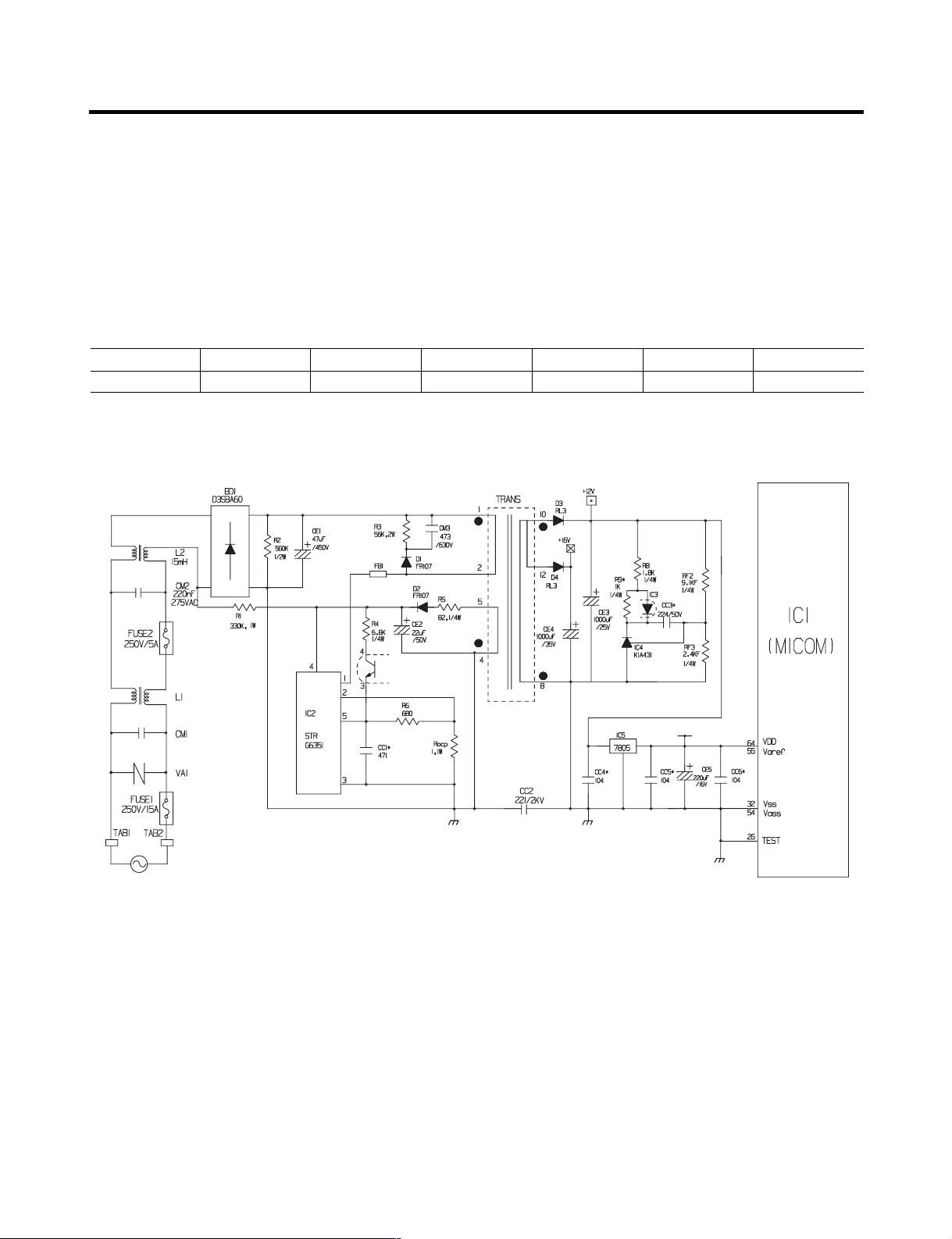
EXPLANATION FOR MICOM CIRCUIT
1. Explanation for PWB circuit
1-1. Power circuit
The power circuit includes a Switched Mode Power Supply (SMPS). It consists of a rectifier (BD1 and CE1) converting AC
to DC, a switch (IC2) switching the DC voltage, a transformer, and a feedback circuit (IC3 and IC4).
Caution : Since high voltage (160 Vdc) is maintained at the power terminal, wait at least 3 minutes after unplugging the
appliance to check the voltages to allow the current to dissipate.
Voltage of every part is as follows:
Part VA1 CE1 CE2 CE3 CE4 CE5
Voltage 120 Vac 160 Vdc 14 Vdc 12 Vdc 15.5 Vdc 5 Vdc
(1) GR-L267BV(T)R
- 29 -
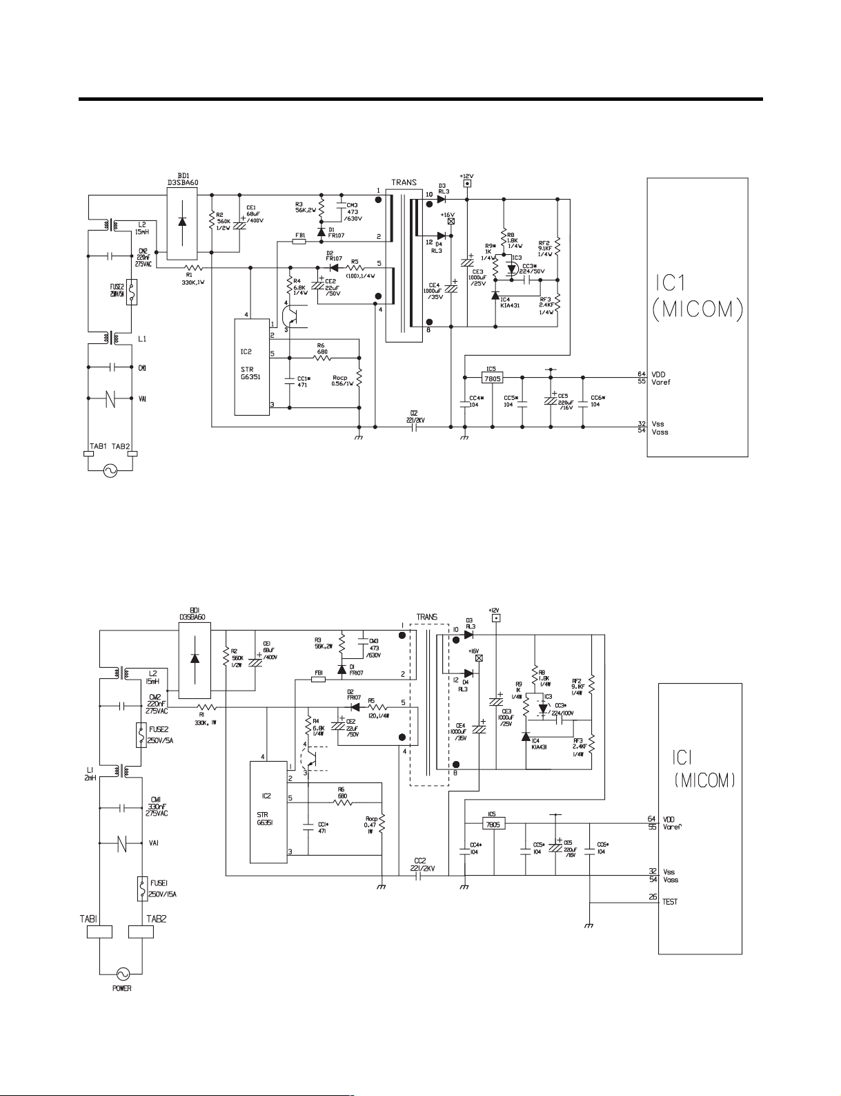
(2) GR-L267BV(T)RA
(3) GR-L267BV(T,S)PA
- 30 -
 Loading...