

Page 1
CAUTION
PLEASE READ CAREFULLY THE SAFETY PRECAUTIONS OF THIS MANUAL
BEFORE CHECKING OR OPERATING THE REFRIGERATOR.
REFRIGERATOR
SERVICE MANUAL
LRSC26925SW
LRSC26925TT
LRSC26923SW
LRSC26923TT
LRSC26915SW
LRSC26915TT
LRSC26912SW
LRSC26912TT
LRSC26940SW
LRSC26940SB
LRSC26940TT
LRSC26940ST
LRSC26941SW
LRSC26941SB
LRSC26941ST
http://biz.lgservice.com
Page 2

CONTENTS
WARNINGS AND PRECAUTIONS FOR SAFETY ................................................................................................................ 3
SPECIFICATIONS................................................................................................................................................................... 4
PARTS IDENTIFICATION ....................................................................................................................................................... 7
HOW TO INSTALL THE REFRIGERATOR .......................................................................................................................... 10
HOW TO ADJUST DOOR HEIGHT.................................................................................................................................... 10
FILTER ................................................................................................................................................................................ 11
HOW TO CONTROL THE ICEMAKER WATER SUPPLY.................................................................................................. 12
MICOM FUNCTION .............................................................................................................................................................. 14
EXPLANATION OF MICOM CIRCUIT.................................................................................................................................. 29
EXPLANATION OF PWB CIRCUIT .....................................................................................................................................29
PWB PARTS DIAGRAM AND LIST .....................................................................................................................................54
PWB CIRCUIT DIAGRAM ...................................................................................................................................................67
ICE MAKER AND DISPENSER WORKING PRINCIPLES AND REPAIR...........................................................................73
WORKING PRINCIPLES.................................................................................................................................................... 73
FUNCTION OF ICE MAKER .............................................................................................................................................. 74
ICE MAKER TROUBLESHOOTING................................................................................................................................... 77
ICE MAKER CIRCUIT .........................................................................................................................................................79
CIRCUIT................................................................................................................................................................................ 80
TROUBLE DIAGNOSIS........................................................................................................................................................ 83
TROUBLESHOOTING ....................................................................................................................................................... 83
FAULTS .............................................................................................................................................................................. 93
COOLING CYCLE HEAVY REPAIR ................................................................................................................................. 110
HOW TO DEAL WITH CLAIMS ........................................................................................................................................ 117
HOW TO DISASSEMBLE AND ASSEMBLE..................................................................................................................... 122
DOOR............................................................................................................................................................................... 122
HANDLE ........................................................................................................................................................................... 123
FAN SHROUD GRILLE .................................................................................................................................................... 124
ICEMAKER ASSEMBLY................................................................................................................................................... 124
DISPENSER..................................................................................................................................................................... 125
EXPLODED VIEW .............................................................................................................................................................. 127
REPLACEMENT PARTS LIST ........................................................................................................................................... 143
- 2 -
Page 3

WARNINGS AND PRECAUTIONS FOR SAFETY
Please observe the following safety precautions to use the
refrigerator safely and correctly and to prevent accident or
injury when servicing.
1. Be careful of an electric shock. Disconnect power cord
from wall outlet and wait for more than three minutes
before replacing PWB parts. Shut off the power
whenever replacing and repairing electric components.
2. When connecting power cord, please wait for more than
five minutes after power cord was disconnected from the
wall outlet.
3. Please check if the power plug is pressed by the
refrigerator against the wall. If the power plug was
damaged, it could cause fire or electric shock.
4. If the wall outlet is overloaded, it may cause a fire.
Please use a dedicated circuit for the refrigerator.
5. Please make sure the outlet is properly grounded.
Particularly in a wet or damp area.
6. Use standard electrical components.
7. Make sure hooks are correctly engaged.
Remove dust and foreign materials from the housing
and connecting parts.
8. Do not fray, damage, run over, kink, bend, pull out, or
twist the power cord.
9. Please check for evidence of moisture intrusion in the
electrical components. Replace the parts or mask with
insulation tape if moisture intrusion was confirmed.
10. Do not touch the icemaker with hands or tools to
confirm the operation of geared motor.
11. Do not suggest that customers repair their refrigerator
themselves. This work requires special tools and
knowledge. Non-professionals could cause fire, injury,
or damage to the product.
12. Do not store flammable materials such as ether,
benzene, alcohol, chemicals, gas, or medicine in the
refrigerator.
13. Do not put anything on top of the refrigerator,
especially something containing water, like a vase.
14. Do not put glass bottles with full of water into the
freezer. The contents will freeze and break the glass
bottles.
15. When you scrap or discard the refrigerator, remove the
doors and dispose of it where children are not likely to
play in or around it.
- 3 -
Page 4
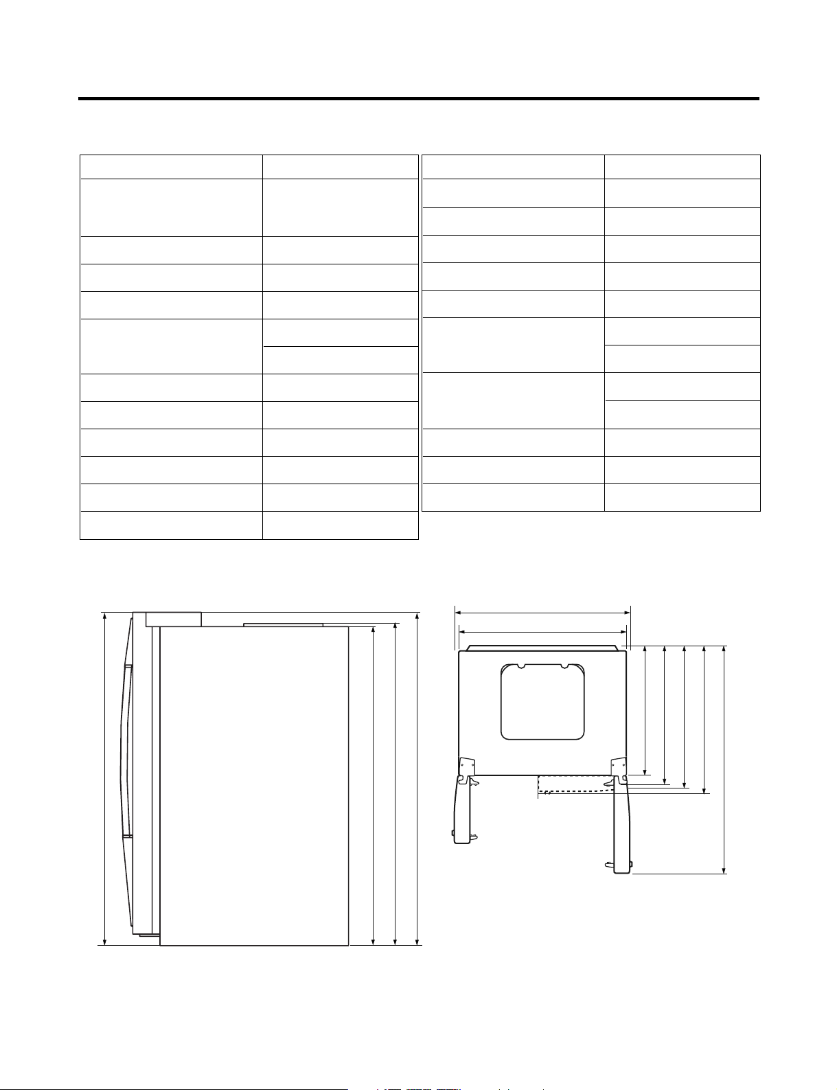
SPECIFICATIONS
724 mm (28
1
/
2
in.)
1004 mm (391/2 in.)
908 mm (39
11
/16 in.)
779 mm (30
5
/
8
in.)
829 mm (32
5
/
8
in.)
897 mm (35
5
/
16
in.)
1261 mm (49
5
/
8
in.)
1741.5 mm (68
1
/
2
in.)
1746.5 mm (68
3
/
4
in.)
1771 mm (69
11
/
16
in.)
1771 mm (69
11
/
16
in.)
1. Ref No. : GR-L267BV(T,S)PA
ITEMS SPECIFICATIONS
DIMENSIONS 908 X 896 X 1771 mm
W
X D X
H (35
NET WEIGHT 149 kg (328.5 lbs.)
COOLING SYSTEM Fan Cooling
TEMPERATURE CONTROL Micom Control
DEFROSTING SYSTEM Full Automatic
INSULATION Cyclo-Pentane
COMPRESSOR PTC Starting Type
EVAPORATOR Fin Tube Type
CONDENSER Wire Condenser
REFRIGERANT R134a (185g) (6
LUBRICATING OIL FREOL @10G (320 cc)
11
/16X355/16X6911/16 in.)
Heater Defrost
1
/2 oz.)
ITEMS SPECIFICATIONS
DRIER MOLECULAR SIEVE XH-7
CAPILLARY TUBE ID Ø0.83
FIRST DEFROST 4 - 5 Hours
DEFROST CYCLE 13 - 15 Hours
DEFROSTING DEVICE Heater, Sheath
ANTI-SWEAT HEATER Dispenser Duct Door Heater
Dispenser Heater
ANTI-FREEZING HEATER Water Tank Heater
Damper Heater
FREEZER LAMP 40W (1 EA)
REFRIGERATOR LAMP 40W (4 EA)
DISPENSER LAMP 15W (1 EA)
Front View Top View
- 4 -
Page 5

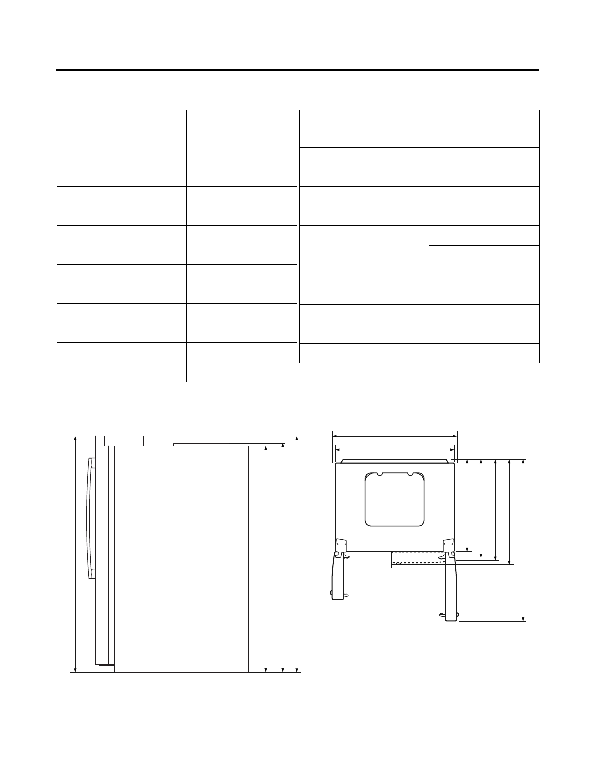
SPECIFICATIONS
2. Ref No. : GR-L267BV(T)RA
ITEMS SPECIFICATIONS
DIMENSIONS 908 X 896 X 1771 mm
W
X D X
H (35
NET WEIGHT 149 kg (328.5 lbs.)
COOLING SYSTEM Fan Cooling
TEMPERATURE CONTROL Micom Control
DEFROSTING SYSTEM Full Automatic
INSULATION Cyclo-Pentane
COMPRESSOR PTC Starting Type
EVAPORATOR Fin Tube Type
CONDENSER Wire Condenser
REFRIGERANT R134a (185g) (6
LUBRICATING OIL FREOL @10G (320 cc)
11
/16X355/16X6911/16 in.)
Heater Defrost
1
/2 oz.)
ITEMS SPECIFICATIONS
DRIER MOLECULAR SIEVE XH-7
CAPILLARY TUBE ID Ø0.83
FIRST DEFROST 4 - 5 Hours
DEFROST CYCLE 13 - 15 Hours
DEFROSTING DEVICE Heater, Sheath
ANTI-SWEAT HEATER Dispenser Duct Door Heater
Dispenser Heater
ANTI-FREEZING HEATER Water Tank Heater
Damper Heater
FREEZER LAMP 40W (1 EA)
REFRIGERATOR LAMP 40W (4 EA)
DISPENSER LAMP 15W (1 EA)
in.)
16
/
11
1771 mm (69
1004 mm (391/2 in.)
11
908 mm (39
in.)
in.)
2
/
1
1741.5 mm (68
Front View Top View
in.)
4
/
16
3
/
11
1771 mm (69
1746.5 mm (68
/16 in.)
in.)
in.)
in.)
2
8
8
/
/
1
/
5
5
724 mm (28
779 mm (30
829 mm (32
in.)
in.)
8
/
16
5
/
5
897 mm (35
1261 mm (49
- 5 -
Page 6
SPECIFICATIONS
3. Ref No. : GR-L267BV(T)R
ITEMS SPECIFICATIONS
DIMENSIONS 908 X 896 X 1771 mm
11
5
W
X
D X H (35
/16
X
35
/16
11
/16
X
69
in.)
NET WEIGHT 149 kg (328.5 lbs.)
COOLING SYSTEM Fan Cooling
TEMPERATURE CONTROL Micom Control
DEFROSTING SYSTEM Full Automatic
Heater Defrost
INSULATION Cyclo-Pentane
COMPRESSOR PTC Starting Type
EVAPORATOR Fin Tube Type
CONDENSER Wire Condenser
REFRIGERANT R134a (185g) (6
1
/2 oz.)
LUBRICATING OIL FREOL @10G (320 cc)
ITEMS SPECIFICATIONS
DRIER MOLECULAR SIEVE XH-7
CAPILLARY TUBE ID Ø0.83
FIRST DEFROST 4 - 5 Hours
DEFROST CYCLE 13 - 15 Hours
DEFROSTING DEVICE Heater, Sheath
ANTI-SWEAT HEATER Dispenser Duct Door Heater
Dispenser Heater
ANTI-FREEZING HEATER Water Tank Heater
Damper Heater
FREEZER LAMP 40W (1 EA)
REFRIGERATOR LAMP 40W (3 EA)
DISPENSER LAMP 15W (1 EA)
in.)
16
/
11
1771 mm (69
1004 mm (391/2 in.)
11
908 mm (39
in.)
in.)
2
/
1
1741.5 mm (68
Front View Top View
in.)
4
/
16
3
/
11
1771 mm (69
1746.5 mm (68
/16 in.)
in.)
in.)
in.)
2
8
8
/
/
1
/
5
5
724 mm (28
779 mm (30
829 mm (32
in.)
in.)
8
8
/
/
5
1
892 mm (35
1261 mm (49
- 6 -
Page 7

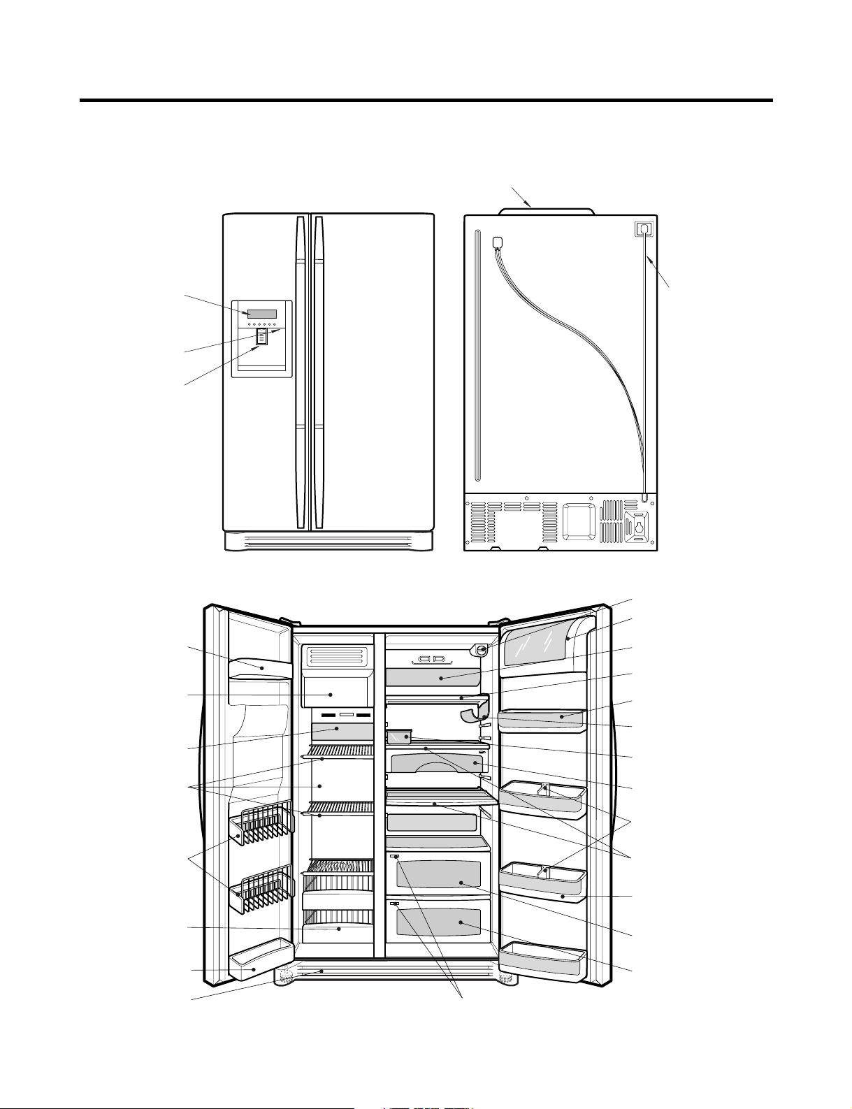
PARTS IDENTIFICATION
Frame Display
Dispenser Lamp
Ice & Water
Dispenser Button
PWB Cover
Water Tubes
Humidity Switch
Lamp
Shelf
Snack Drawer
Vegetable Drawer
OptiChill
Door Rack
Shelf
Grab and Go
Wine Holder
Lamp
Lower Cover
Dairy Product Corner
Door Rack
Drawer
(Wire/Plastic)
Freezer
Compartment
Refrigerator
Compartment
Automatic
Icemaker
Door Rack
Shelf
Bottle Guide
OptiChill Display
Water Filter
Door Rack
Egg Box
1. Ref No. : GR-L267BV(T,S)PA
- 7 -
Page 8
PARTS IDENTIFICATION
Frame Display
Dispenser Lamp
Ice & Water
Dispenser Button
PWB Cover
Water Tubes
Freezer
Compartment
Refrigerator
Compartment
Humidity Switch
Lamp
Shelf
Snack Drawer
Vegetable Drawer
Vegetable Drawer
/Meat Drawer
Door Rack
Shelf
Door Rack
Wine Holder
Lamp
Lower Cover
Dairy Product Corner
Door Rack
Drawer
(Wire/Plastic)
Automatic
Icemaker
Door Rack
Shelf
Bottle Guide
Door Rack
Water Filter
Egg Box
2. Ref No. : GR-L267BV(T)RA
- 8 -
Page 9

PARTS IDENTIFICATION
Frame Display
Dispenser Lamp
Ice & Water
Dispenser Button
PWB Cover
Water Tubes
Lamp
Shelf
Snack Drawer
Vegetable Drawer
Vegetable Drawer
/Meat Drawer
Door Rack
Shelf
Door Rack
Lamp
Lower Cover
Dairy Product Corner
Door Rack
Drawer
(Wire/Plastic)
Freezer
Compartment
Refrigerator
Compartment
Automatic
Icemaker
Door Rack
Shelf
Door Rack
Water Filter
Humidity Switch
Bottle Guide
Egg Box
3. Ref No. : GR-L267BV(T)R
- 9 -
Page 10

HOW TO INSTALL REFRIGERATOR
Adjusting
Screw
Driver
Height
Difference
Height
Difference
Height
Difference
Height
Difference
1
2
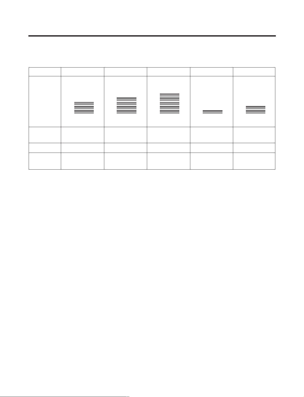
1. How to Adjust Door Height of Refrigerator
■ Make the refrigerator level first. (If the refrigerator is not installed on a flat floor, the height of freezer and refrigerator
door may not be the same.)
1. If the freezer door is lower than the refrigerator
door:
2. If the freezer door is higher than the refrigerator
door:
Insert a driver into the groove if the adjusting
screw and turn in the direction of the arrow (clockwise)
until the refrigerator is level.
- 10 -
Insert a driver into the groove if the adjusting
screw and turn in the direction of the arrow (clockwise)
until the refrigerator is level.
Page 11
HOW TO INSTALL REFRIGERATOR
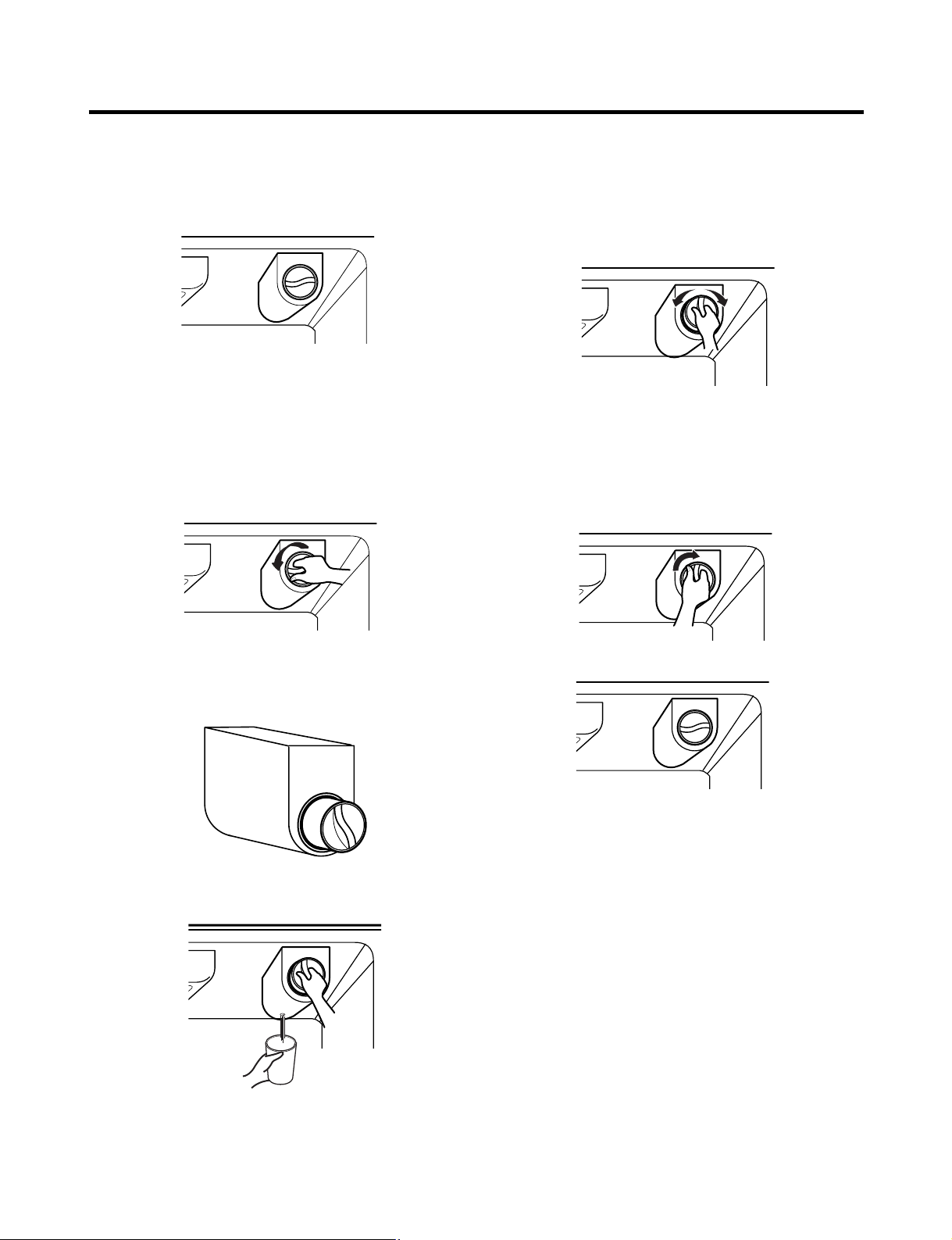
2. Filter
Replace the filter when the indicator light comes on or the
performance of the icemker or water dispenser decreases
noticeably.
After changing the water filter cartridge, reset the water
filter status display and indicator light by pressing and
holding the BUTTON for 3 seconds.(page 18)
1. Remove the old cartridge.
Twist the knob of the cartridge counter clockwise.
2. Replace with a new cartridge.
Take the new cartridge out of its packaging and remove
protective cover from the o-rings.
With cartridge knob in the vertical position, push the new
filter cartridge into the cover until it stops.
If you can’t turn the filter from side to side, it isn’t fully
inserted. Push it in firmly and twist it into place. You will
hear the snap when it clicks into place.
Using the handle, twist the cartridge clockwise about 1/4
turn.
When the cartridge is removed, you will feel it click .
Pull out the cartridge.
NOTE: There will be some water(25cc) in the filter
cartridge. Some spilling may occur. Catch it in a
bowl or towel.
3. Flush the Water System After Replacing Filter Dispense
water through the water dispenser for 3 minutes to
purge the system.
There may be a little air in the line, causing noise or
hissing. Run the water at the dispenser until the hissing
stops to purge the air from the system.
NOTE: - To purchase replacement water filter cartridges,
visit your local appliance dealer or part distributor.
- You can also visit our website :
www.lgappliances.com or call 1-877-714-7481.
- 11 -
Page 12
HOW TO INSTALL REFRIGERATOR
2
1
Test Switch
Confirm the amount
of water
Ice maker
Too much
Too little
Optimum level
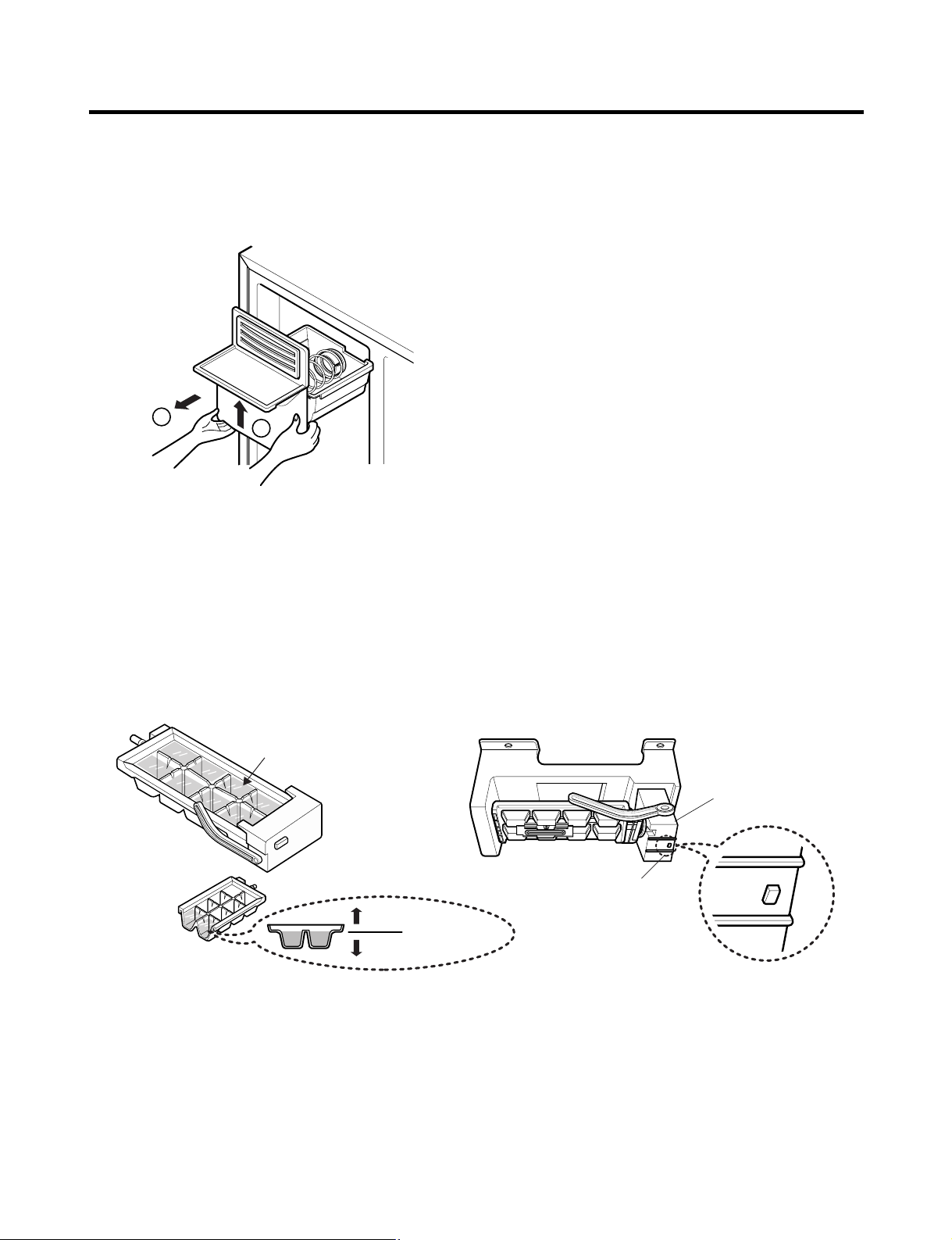
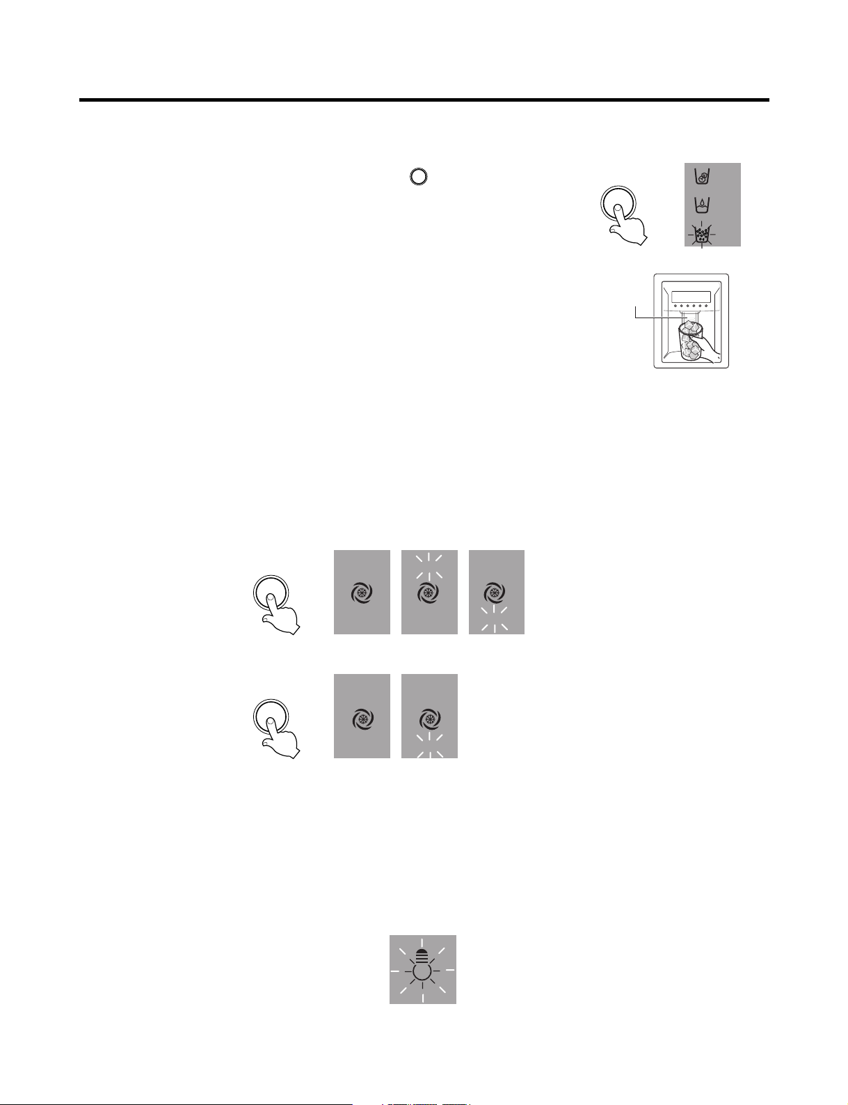
3. How to Control the Amount of Water Supplied to Icemaker.
3-1. Confirm the amount of water supplied to the icemaker.
1. Pull out the ice bin shelf in the upper part of the freezer compartment.
Caution : • Do not put hands or tools into the chute to confirm
the operation of geared motor.
It may damage the refrigerator or hurt your hands.
2. Apply electricity after connecting water pipe.
1) Press test switch under the icemaker for two seconds as shown below.
2) The bell rings(ding~dong) and ice tray rotates and water comes out from the icemaker water tube.
3) The water shall be supplied two or three times into the tray. The amount of water supplied for each time is small.
Put a water container under the ice tray and press test switch.
4) When ice tray rotates, the water in it will spill. Collect the spilt water and throw away into the sink.
5) When ice tray has finished rotation, water comes out from the water tube. Confirm the amounts of water in the ice tray.
(refer to fig. The optimum amount of water is 110cc)
* It is acceptable if the adjusted level of water is a bit smaller than optimum level.
- 12 -
Page 13

HOW TO INSTALL REFRIGERATOR
(+) Driver
1
ON
Switch ON
Switch OFF
23
Confirm the amount
of water
Optimum level
3-2. Control the amount of water supplied to the icemaker.
Caution : • Please unplug the power cord from the wall outlet and wait for more than three minutes before disconnecting
PWB cover as 310V is applied in the control panel.
1. Disconnect PWB cover from the upper part of the refrigerator.
2. Adjust the amount of water supplied by using DIP switch.
■ Water Supplying Time Control Option
REMARKS
supplied depends on DIP
switch setting conditions
and water pressure as it
is a direct tap water
connection type. (the
water supplied is
generally 80 cc to 120 cc)
PWB.
No
1
2
3
4
5
6
7
8
GR-L267BV(T)R GR-L267BV(T)RA, GR-L267BV(T,S)PA
DIP SWITCH SETTING
S1 S2
OFF OFF 6.5 SEC
ON OFF 5.5 SEC
OFF ON 7.5 SEC
ON ON 8.5 SEC
WATER
SUPPLY TIME
DIP SWITCH SETTING
S1 S2 S3
OFF OFF OFF 6.5 SEC
ON OFF OFF 5.5 SEC
OFF ON OFF 6 SEC
ON ON OFF 7 SEC
OFF OFF ON 7.5 SEC
ON OFF ON 8 SEC
OFF ON ON 9 SEC
ON ON ON 10 SEC
WATER
SUPPLY TIME
* The quantity of water
* DIP switch is on the main
1) The water supplying time is set at five seconds when the refrigerator is delivered.
2) The amount of water supplied depends on the setting time and water pressure (city water pressure).
3) If ice cube is too small, increase the water supplying time. This happens when too small water is supplied into the ice tray.
4) If ice cube sticks together, decrease the water supplying time. This happens when too much water is supplied into the ice tray.
Caution : When adjusting the amount of water supplied, adjust step by step. Otherwise the water may spill over.
3. When adjustment of control switch for the amount of water supplied is complete, check the level of water in the ice tray.
- 13 -
Page 14
MICOM FUNCTION
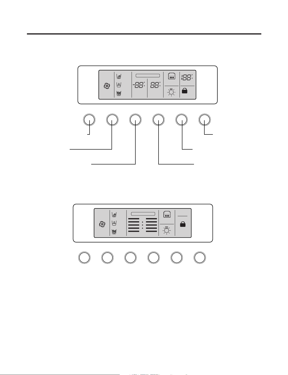
EXPRESS/JET FRZ DISPENSER FREEZER REFRIGERATOR FILTER/LIGHT LOCK
Dispenser selection
button
Express Freezer/Jet Freezer
function selection button
Dispenser and button
Lock button
Dispenser Lamp On/Off button/
Filter status display RESET button
Temperature adjustment button
for refrigerator compartment
Temperature adjustment button
for freezer compartment
EXPRESS
FRZ
(EXPRESS)
ON
(JET)
CUBE
ROOM TEMPERATURE
LOCK
DISPENSER & BUTTON
F
WATER
CRUSH
C
3 SECS
DIGITAL CONTROL
FRZ TEMP
F
C
F
C
REF TEMP
FILTER RESET
HOLD 3SECS
FILTER
EXPRESS DISPENSER FREEZER
REFRIGERATOR
FILTER RESET/LIGHT
LOCK
EXPRESS
FRZ
ON
CUBE
LOCK
DISPENSER
BUTTON
WATER
CRUSH
3 SECS
DIGITAL CONTROL
FRZ TEMP REF TEMP
COLDEST
COLD
FILTER RESET
HOLD 3SECS
FILTER
1. Monitor Panel
1-1. GR-L267BV(T)RA, GR-L267BV(T, S)PA
1-2. GR-L267BV(T)R
- 14 -
Page 15
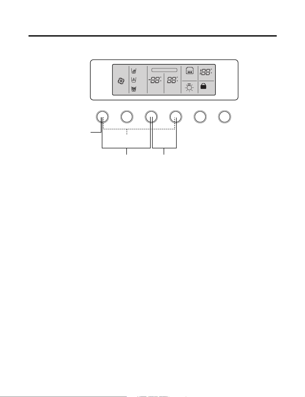
MICOM FUNCTION
EXPRESS/JET FRZ DISPENSER FREEZER REFRIGERATOR FILTER/LIGHT LOCK
Display Power
saving Mode
Exhibition Mode
EXPRESS
FRZ
(EXPRESS)
ON
(JET)
CUBE
ROOM TEMPERATURE
LOCK
DISPENSER & BUTTON
F
WATER
CRUSH
C
3 SECS
DIGITAL CONTROL
FRZ TEMP
F
C
F
C
REF TEMP
FILTER RESET
HOLD 3SECS
FILTER
Change Display Degree from
Fahrenheit to Centigrade Mode
Buzzer sound
mute Mode
1-3. Display Second Function
1. Buzzer sound mute Mode
The buzzer sound is set to OFF.
It activates by sounding the recognition sound of “Ding~” after pressing and holding “Express FRZ” button more than 5
seconds. It inactivates when resetting the mode power.
2. Display Power saving Mode
It places display in standby mode until door is opened.
Press “Freezer” and “Express FRZ” buttons simultaneously to turn all leds become ON and then OFF with the recognition
sound of “Ding~” after 5 seconds. (Be sure not to press only one button to work.)
Once the mode activates, the display is always OFF. Until door is opened or display button is pressed. When 30 seconds
has elapsed after closing door or pressing button, the display turns OFF. To deactivate this mode is same as the
activation methods. The mode inactivates when resetting the power.
3. Change Display Degree to Centigrade Mode from Fahrenheit Mode
To change temperature display from Fahrenheit to Celsius press and hold “FREEZER” and “REFRIGERATOR” buttons
simultaneously for more than 5 seconds. Do the same to convert back to Celsius.
4. Exhibition Mode
This function is available when exhibiting a refrigerator in the shopping moll.
Function is inserted with recognition sound “Ding ~” if pressing both the “Freezer” button and the “REFRIGERATOR”
button at the same time for more than 5 seconds. If function is inserted, all basic refreezing functions at the R/F room and
the Storage room (COMP, F-FAN, C-FAN) turns off and the display normally operates. However, the dispenser function
normally operates.
The DEMO stops if pressing the button during DISPLAY DEMO, DEMO stops and the display normally operates but
performs DEMO operation again if not pressing the button again for more than 30 seconds (DEMO: Display scenario
when using the display).
Release method is same as input method.
The mode is released if power is reset.
- 15 -
Page 16
MICOM FUNCTION
2. Description of Function
2-1-1. Function of Temperature Selection
Division Power Initially On 1st Press 2st Press 3th Press 4th Press
Setting
temperature
Temperature
Control
Freezer Control
Refrigeration
Control
* The temperature can vary ±3 °C depending on the load condition.
5
4
3
2
1
Medium Medium Max Max Min Medium Min
-2 °F -5 °F -8 °F7 °F1 °F
37 °F 34 °F 32 °F 46 °F 41 °F
5
4
3
2
1
5
4
3
2
1
5
4
3
2
1
5
4
3
2
1
❉ Whenever pressing button, setting is repeated in the order of (Medium) ➝ (Medium Max) ➝ (Max) ➝ (Min) ➝
(Medium Min).
• The actual inner temperature varies depending on the food status, as the indicated setting temperature is a target
temperature, not actual temperature within refrigerator.
• Refrigeration function is weak in the initial time. Please adjust temperature as above after using refrigerator for minimum
2~3 days.
• Freezer Notch is fixed “Medium Max” unconcerned with display Notch during ICE Making Control Mode and Ice Maker
Stop switch is selected with “ON”.
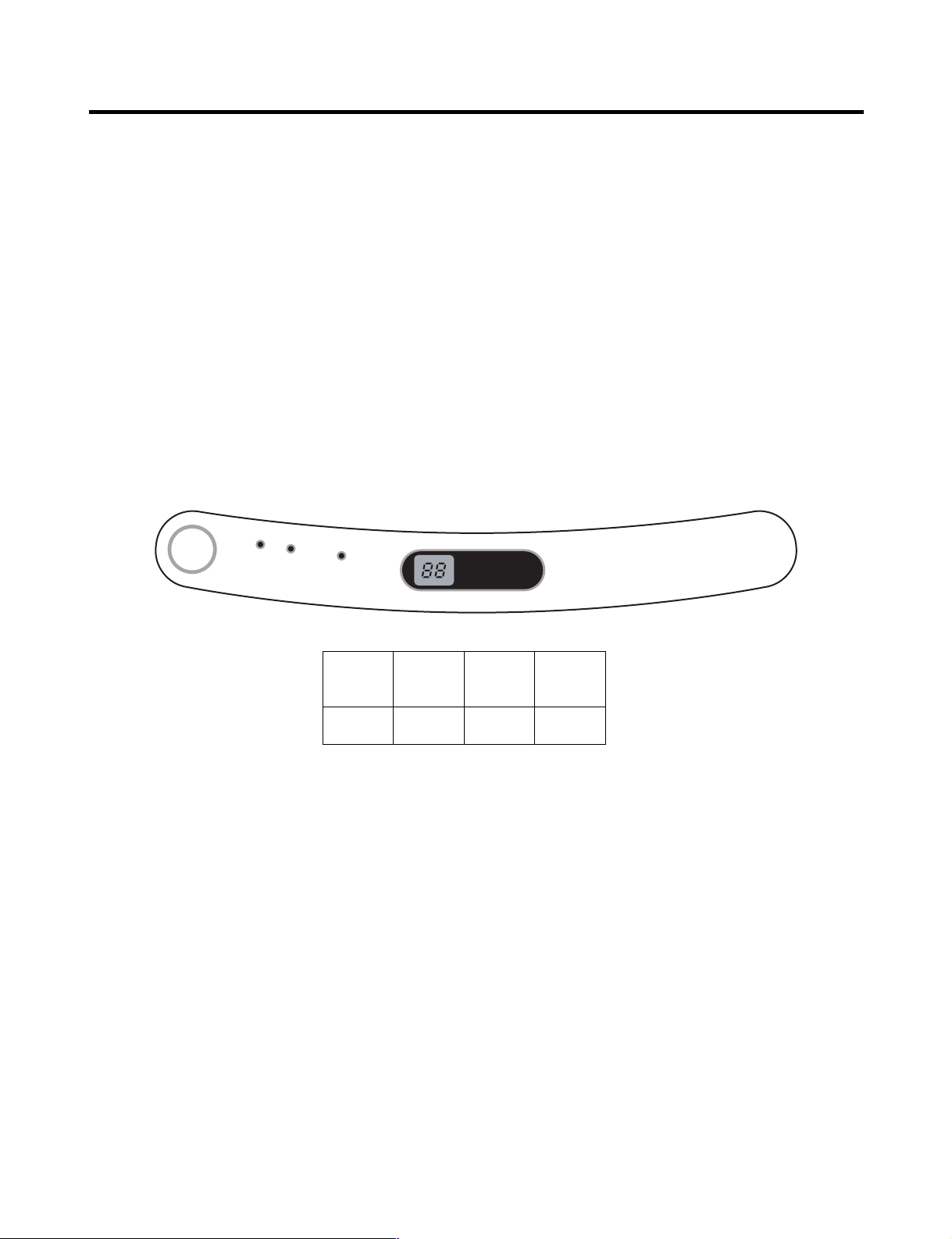
2-1-2. Outside temperature display function
1. Outside temperature sensor at the right Hinge Cover - U of refrigerator senses ambient temperature and displays the
outside temperature in the upper of “ROOM TEMP” text on the display part.
2. Ambient temperature is displayed up to 16°F ~ 120°F and displayed as “Lo” for less than 15°F and as “HI” for more than
121°F. If the ambient temperature sensor fails, it is displayed as “Er”.
3. Since display temperature of outside temperature is temperature sensed by the ambient sensor in the hinge U of the
refrigerator room, it may differ from the outside temperature display of other household electrical appliances.
- 16 -
Page 17
MICOM FUNCTION
LOCK
DISPENSER & BUTTON
3 SECS
LOCK
DISPENSER & BUTTON
3 SECS
LOCK CONTROL
Ex) Select
LOCK
Ex) Select
LOCK again
In initial Power On
/ Filter RESET
Replace indicator
light on
Classification
Filter Status
Display
FILTER RESET
HOLD 3SECS
FILTER
FILTER RESET
HOLD 3SECS
FILTER
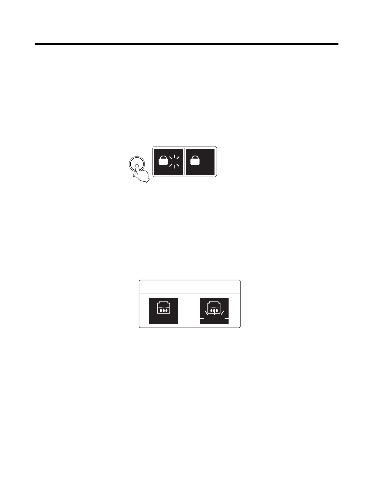
2-1-3. Lock function (dispenser and display button lock)
1. In power application of refrigerator, the “LOCK” text is turned off at the right side of lock graphic of display with the lock
replease status.
2. If desiring to lock the dislay the dispenser and control panel, push on the LOCK button more than 3 seconds. LOCK text
is turned on at the right side of lock graphic of display with lock status.
3. The buzzer sound and control panel and dispenser function is not performed even if pressing display button other than
lock key in the lock status.
4. If desiring to release the lock status and pressing the lock button more than 3 seconds. “LOCK” text is turned off at the
right side of lock graphic of display with the lock release status.
LED
2-1-4. Filter condition display function
1. There is a replacement indicator light for the water filter cartridge on the dispenser.
2. Water filter needs replacement once six months.
3. Water filter light and “FILTER RESET HOLD 3SECS” text turn on to tell you need to replace the filter soon.
4. After replace the filter, press and hold the lock button more than 3seconds.
Then water filter light and “FILTER RESET HOLD 3SECS” text turn off with reset status.
- 17 -
Page 18
MICOM FUNCTION
DISPENSER
LED
CUBE
WATER
CRUSH
Pressing
Switch
LED (GR-L267BV(T,S)PA)
LED (GR-L267BV(T)R, GR-L267BV(T)RA)
EXPRESS/JET FRZ
EXPRESS/JET FRZ
EXPRESS
FRZ
EXPRESS EXPRESS EXPRESS
ON
EXPRESS
FRZ
ON
JET JET JET
Dispenser Iight ON/OFF
LED
DISPENSER
2-2. Dispenser use selection
You can select water or ice.
❉ Please select water, slice ice and square ice by pressing button as you
desire.
❉ Please press the push button lightly by catching and pushing in cup.
• Each graphic is indicated for the selected function.
• “Tak!” sounds if 5 seconds pass after ice comes out.
It is sound that the outlet of ice is closed.
REFERENCE : Please wait for 2-3 seconds in order to take final ice slices or drops
of water when taking out cup from the pressing switches after
taking ice or water.
2-3. Express freezing/JET freezing selection
Please select this function for prompt freezer.
• Function is repeated following below whenever pressing EXPRESS/JET FRZ button.
• The arrow mark graphic remains at the On status after flickering 4 times when selecting Special Refrigeration “EXPRESS
FRZ” or “JET FRZ”.
• Expressing freezer or jet freezer function automatically turns off if a fixed time passes.
2-4. Dispenser Light
• Dispenser switch or dispenser light button turn the dispenser light in the dispenser on and off.
• The dispenser light Function is repeated following below whenever pressing “FILTER RESET/LIGHT” button.
• If dispenser light continuously turns on more than 7 minutes with dispenser light button, the dispenser light turns off
automatically by compulsion.
- 18 -
Page 19

MICOM FUNCTION
2-5. Express freezing
1. Express freezing is function to improve cooling speed of the freezing room by consecutively operating compressors and
freezing room fan.
2. Express freezing is released if power failure occurs and then returns to the original status.
3. Temperature setting is not changed even if selecting the express freezing.
4. The change of temperature setting at the freezing room or the cold storage room is allowed with express freezing
selected and prrocessed.
5. The cold storage room operates the status currently set with Express freezing selected and procesed.
6. If selecting the Express freezing, the Express freezing function is released after continuously operating compressor and
freezing room fan.
7. If frost removal starting time is arrived during Express freezing, Express freezing operation is done only for the remaining
time after completion of frost removal when the Express freezing operation time passes 90 minutes. If passing 90
minutes, Express freezing operation is done only for 2 hours after completion of frost removal.
8. If pressing Express freezing button during frost removal, the Express freezing LCD or LED is turned on but if pressing the
Express freezing, compressor operates after the remaining time has passed.
9. If selection Express freezing within 7 minutes (delay for 7 minutes of compressor) after the compressor stops,
compressor operates after the remaining time has passed.
10. The freezing room fan motor operates at the high speed of RPM during operation of Express freezing.
2-6. Jet Freezing (GR-L267BV(T,S)PA Model)
1. Jet freezing is function to improve cooling speed of the Jet Freezing Room in the freezer room by consecutively operating
compressor and Jet freezing box fan motor.
2. Jet freezing is released if power failure occurs and then returns to the original status.
3. Display temperature setting is not changed even if selectig the jet freezing.
4. If Jet Freezing is selected, comp (after comp delay time passes) and fan motor in freezer room will be on. The
temperature in refrigerator room will be drop and fan motor will be off for certain time, and then the fan motor in Jet
Freezing box will be on for maximum 2 hours.
After that, terminate the Jet Freezing function and display as off status.
5. To prevent from being frozen, the fan motor of jet freezing box will be on for 10 sec. by every 1hour when it doesn’t
operate.
6. The fan motor of jet freezing box will not be detected as a failure. (dc 12v operation)
7. When checking the jet freezing function, the fan motor of jet freezing box to be for 1 min. In case of pressing the freezer
adjust button and express freezing button over 1 sec.
- 19 -
Page 20
MICOM FUNCTION
°F / SET TEMP
/ TIME REMAINING
MIN
FRUIT
VEGE
CHILED
ROOM
PARTIAL
FREEZING
SELECT
HR
2-7. OptiChill Function (GR-L267BV(T,S)PA Model)
1. The OptiChill is positioned at the bottom of fresh food room separately and allow a user to select and adjust a desired
temperature according to kinds of food such as meat, fish, vegetables and fruits and so on. The selected temperature to
any kinds of food let user to keep their food longer.
2. OptiChill comprises of OptiChill sensor at the rear of OptiChill and a damper between OptiChill and freezer room and a
temperature adjusting display at the top of it.
3. When powered on, the initial NOTCH of OptiChill display will be on “FRUIT VEGE”.
If only R-DOOR is OPENED, OptiChill LED will be ON.
4. Every time pressing the button, the LED shows “FRUIT VEGE”(39°F) → “CHILED ROOM”(30°F) → “PARTIAL FREEZING
(27°F)” → “FRUIT VEGE”(39°F) in orders and also shows a target temperature to be controlled at the same time, then the
NOTCH will be changed relatively.
5. The OptiChill sensor detects a desired temperature at micom, and if the temperature is satisfied, the OptiChill damper will
be closed and if the temperature is unsatisfied, the OptiChill damper will be opened and then the temperature will be
cooled.
6. If the OptiChill damper doesn’t operate for 1 hour, it will be physically operated for seconds to prevent from being frozen.
NOTCH
Partial
Freezing
Chilled
Room
Fruit
VEGE
Display 27°F30°F39°F
- 20 -
Page 21
MICOM FUNCTION
Doors of freezing /
cold storage room
or home bar
BUZZER
Closing
Opening
Within
a minute
A minute
30
seconds30seconds30seconds
Opening
Closing Closing
3 Times 3 Times 3 Times 3 Times
2-8. Control of variable type of freezing fan
1. To increase cooling speed and load response speed, MICOM variably controls freezing room fan motor at the high speed
of RPM and standard RPM.
2. MICOM only operates in the input of initial power or express freezing operation or load response operation for the high
speed of RPM and operates in the standard RPM in other general operation.
3. If opening doors of freezing / cold storage room or home bar while fan motor in the freezing room operates, the freezing
room fan motor normally operates (If being operated in the high speed of RPM, it converts operation to the standard
RPM). However, if opening doors of freezing room or home bar, the freezing room fan motor stops.
4. As for monitoring of BLDC fan motor error in the freezing room, MICOM immediately stops the fan motor by determining
that the BLDC fan motor is locked or poor if there would be position signal for more than 115 seconds at the BLDC motor.
Then it displays failure (refer to failure diagnosis function table) at the display part of refrigerator, the BLDC motor doesn’t
operate more. If you want to operate the BLDC motor, turn off and on power resource.
2-9. Control of cooling fan motor
1. The cooling fan motor performs ON/OFF control by linking with the COMP.
2. It controls at the single RPM without varying RPM.
3. Failure sensing method is same as in fan motor of freezing fan motor (refer to failure diagnosis function table for failure
display).
2-10. Door opening alarm
1. Buzzer generates alarm sound if doors are not closed even when more than a minute consecutively has passed with
doors of freezing / cold storage room or home bar opened.
2. Buzzer rings three times in the interval of 0.5 second after the first one-minute has passed after doors are opened and
then repeats three times of On/Off alarm in the cycle of every 30 seconds.
3. If all the doors of freezing / cold storage room or home bar are closed during door open alarm, alarm is immediately
released.
2-11. Ringing of button selection buzzer
1. If pressing the front display button, “Ding ~ “ sound rings.
- 21 -
Page 22

MICOM FUNCTION
2-12. Ringing of compulsory operation, compulsory frost removal buzzer
1. If pressing the test button in the main PCB, “Phi ~” sound rings.
2. In selecting compulsory operation, alarm sound is repeated and completed in the cycle of On for 0.2 second and Off for
1.8 second three times.
3. In selecting compulsory frost removal, alarm sound is repeated and completed in the cycle of On for 0.2 second , Off for
0.2 second, On for 0.2 second and Off for 1.4 second three times.
2-13. Frost removal function
1. Frost removal is performed whenever total operation time of compressor becomes 7 ~ 7.5 hour.
2. In providing initial power (or returning power failure), frost removal starts whenever total operation time of compressor
becomes 4 ~ 4.5 hour.
3. Frost removal is completed if temperature of a frost removal sensor becomes more than 5°C after starting frost removal.
Poor frost removal is not displaced if it does not arrive at 5°C even if two hours have passed after starting frost removal.
4. No removal is done if frost removal sensor becomes poor (snapping or short-circuit).
2-14. Refrigerator room lamp automatically off
• Refrigerator room lamp turn on and off by refrigerator door switch.
• If refrigerator room lamp continuously turns on more than 7 minutes, the refrigerator room lamp turns off automatically by
compulsion.
- 22 -
Page 23
MICOM FUNCTION
POWER
ON
COMP
ON
F-FAN
&
C-FAN
ON
R-STEP
MOTOR
DAMPER
ON
OPTICHILL
STEP
DAMPER
MOTOR
ON
FROST
REMOVAL
HEATER
OFF
FROST
REMOVAL
HEATER
ON
DAMPER
&
DUCT DOOR
&
OPTICHILL
HEATER ON
DAMPER
&
DUCT DOOR
&
OPTICHILL
HEATER OFF
0.3
sec.
6.0
sec.
0.3
sec.
0.3
sec.
0.3
sec.
POWER
ON
0.3
sec.
PIPE
&
DISP'
HEATER
OFF
0.3
sec.
COMP
ON
0.3
sec.
F-FAN
&
C-FAN
ON
0.3
sec.
R-STEP
MOTOR
DAMPER
ON
0.3
sec.
OPTICHILL
STEP
DAMPER
MOTOR
ON
PIPE
&
DISP'
HEATER
ON
TEST
SWITCH
(PRESS
Once)
OTHER
LOAD
OFF
COMP
ON
F-FAN
&
C-FAN
ON
R-STEP
MOTOR
DAMPER
ON
OPTICHILL
STEP
DAMPER
MOTOR
CLOSE
TEST
SWITCH
(PRESS
2 Times)
COMP
OFF
F-FAN
&
C-FAN
OFF
FROST
REMOVAL
HEATER
ON
R-STEP
MOTOR
DAMPER
CLOSE
0.3
sec.
0.3
sec.
0.3
sec.
0.3
sec.
0.3
sec.
0.3
sec.
0.3
sec.
0.3
sec.
0.3
sec.
0.3
sec.
0.3
sec.
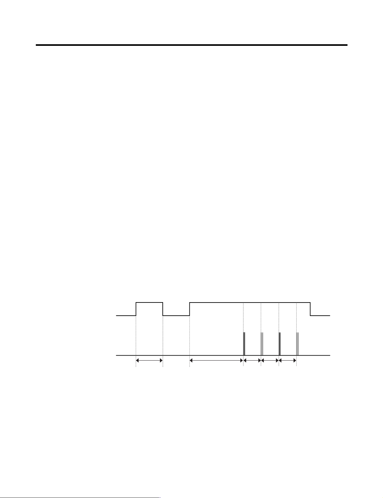
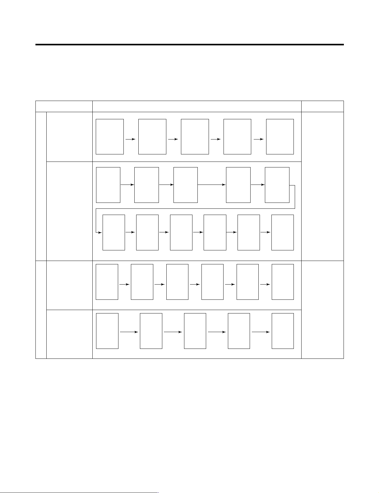
2-15. Sequential operation of built-in product
Built-in products such as compressor, frost removal heater, freezing room fan, Cooling Fan and step motor damper are
sequentially operated as follows for preventing noise and part damage occurred due to simultaneous operation of a lot of
parts in applying initial power and completing test.
Function Load Operation Sequence Remark
In applying Initial power TEST MODE
When temperature
of a frost removal
sensor becomes
more than 45°C
(In purchase,
movement)
When
temperature of a
frost removal
sensor becomes
less than 45°C
(In power failure,
service)
Test mode 1
(Compulsory
function)
Test mode 2
(Compulsory frost
removal)
If error occurs
during operation,
initial operation is
not done.
■
Sequence of
load operation
when closing
F-room and
R-room.
If pressing switch
once more in the
test mode 2 or
temperature of a
frost removal
sensor is more
than 5°C, it
immediately
returns to the test
mode for initial
operation
(COMP operates
after 7 minutes).
- 23 -
Page 24
MICOM FUNCTION
EXPRESS
FRZ
ON
CUBE
LOCK
DISPENSER
BUTTON
WATER
CRUSH
3 SECS
DIGITAL CONTROL
FRZ TEMP REF TEMP
COLDEST
COLD
FILTER RESET
HOLD 3SECS
FILTER
C E F DG
FRZ
TEMP
Trouble Code
Index
Trouble Code
F4
F3
F2
F1
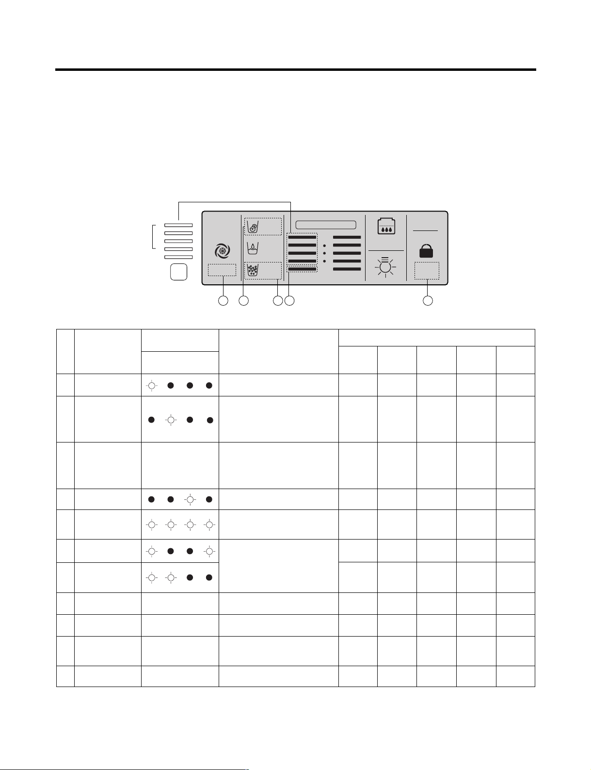
2-16. Failure Diagnosis Function
1. Failure diagnosis function is function to facilitate service when nonconforming matters affecting performance of product
during use of product.
2. In occurrence of failure, pressing the function adjustment button does not perform function.
3. If nonconforming matters occurred are released during display of failure code, MICOM returns to the original state (Reset).
4. Failure code is displayed on the display part of setting temperature for the freezing room and the display part of setting
temperature for the cold storage room of display, which are placed at the display part of a refrigerator. All the display
graphics other than a failure code are turned off.
(1) GR-L267BV(T)R Model
: On l : Off ˇ : Normal
No. Item
1
Abnormal
freezer sensor
2
Abnormal refrigerator
sensor 1 (R1)
(Upper part in the
refrigerator
compartment)
3
Abnormal refrigerator
sensor 2 (R2)
(Upper part in the
refrigerator
compartment)
Abnormal defrost
4
sensor
Failed defrosting
5
Abnormal freezing
6
BLDC motor
Abnormal cooling
7
BLDC motor
Abnormal
8
ambient sensor
Abnormal
9
ice-maker sensor
Abnormal
10
ice-maker unit
Abnormal W/T
11
sensor
Trouble Code Index
F1 F2 F3 F4
Normal display
(Note 1)
Normal display
(Note 1)
Normal display
(Note 1)
Normal display
(Note 1)
Normal display
(Note 1)
Contents of failure
Compressor
Freezer sensor short circuit
ON for 15minutes /
OFF for 15minutes
Refrigerator sensor1 short circuit
Refrigerator sensor2 short circuit
Abnormal short circuit
Defrost heater, temperature fuse short
circuit, unplugged connector(indicated
4 hour later after trouble)
Motor defect, hooked of lead wire
to fan, contact of structures with
fan, short or open of lead
wire(there is no signal of BLDC
motor more than 115 seconds in
operation of fan motor)
Ambient sensor short circuit
Ice-maker sensor short circuit
Faulty ice-maker unit morot or hall
ic, lead wire short circuit, faulty
motor driving circuit
Water Tank sensor short circuit
Product operation status in failure
Freezing
BLDC motor
Standard
Cooling
BLDC motor
●●
RPM
Standard
●●
●●
RPM
Standard
●●
●●
RPM
Standard
●●
●●
RPM
Standard
●●
●●
RPM
●●
●●
OFF
Standard
●●
OFF
RPM
●●
●●
●●
●●
●●
●●
●●
●●
●●
●●
●●
●●
Defrost
Heater
●●
●●
●●
No defrost
●●
●●
●●
●●
●●
●●
●●
Stepping
motor damper
●●
Full opening for
10 minutes/
Full closing for
15 minutes
●●
●●
●●
●●
●●
●●
●●
●●
●●
- 24 -
Page 25
MICOM FUNCTION
Failure Code Indication Part
EXPRESS
FRZ
(EXPRESS)
ON
(JET)
CUBE
ROOM TEMPERATURE
LOCK
DISPENSER & BUTTON
F
WATER
CRUSH
C
3 SECS
DIGITAL CONTROL
FRZ TEMP
F
C
F
C
REF TEMP
FILTER RESET
HOLD 3SECS
FILTER
C F A B
E
D
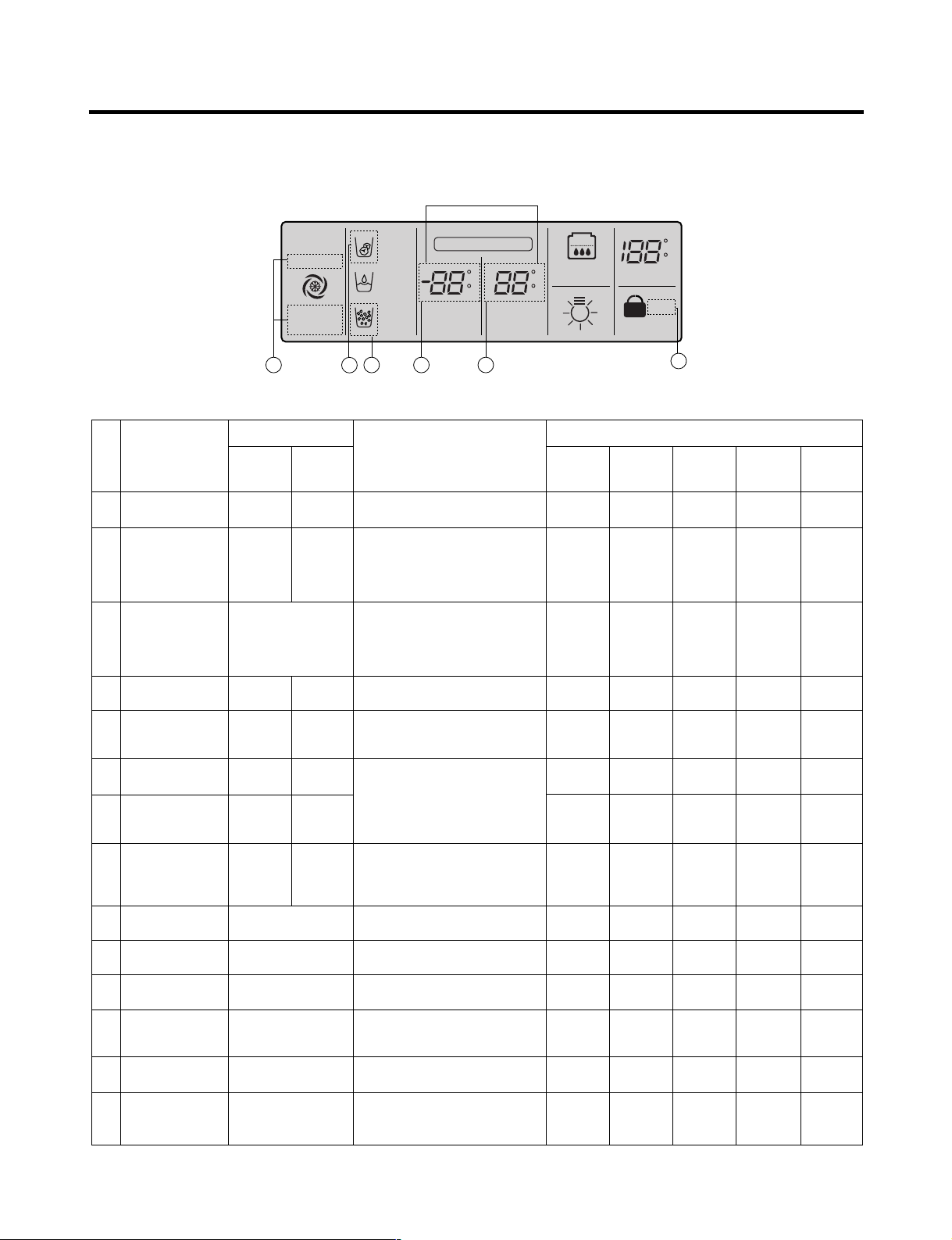
(2) GR-L267BV(T)RA, GR-L267BV(T,S)PA Model
Failure code indication part
No. Item
1
Abnormal
freezer sensor
2
Abnormal refrigerator
sensor 1 (R1)
(Upper part in the
refrigerator
compartment)
3
Abnormal refrigerator
sensor 2 (R2)
(Middle part in the
refrigerator
compartment)
Abnormal defrost
4
sensor
Failed defrosting
5
Abnormal freezing
6
BLDC motor
Abnormal cooling
7
BLDC motor
Abnormal
8
communication
Abnormal
9
ambient sensor
Abnormal
10
Optichill sensor
Abnormal
11
ice-maker sensor
Abnormal
12
ice-maker unit
Abnormal
13
W/T sensor
Abnormal
14
Drive Micom
Communication
Freezer room
notch temperature
display
Er FS
Er rS
Normal display
Er dS
Er dH
Er FF
Er CF
Er CO
Normal display
Normal display
Normal display
Normal display
Normal display
Normal display
Refrigerator room
notch temperature
display
(Note 2)
(Note 2)
(Note 1)
(Note 1)
(Note 1)
(Note 1)
(Note 1)
Contents of failure
Freezer sensor short circuit
Refrigerator sensor1 short circuit
Refrigerator sensor2 short circuit
Abnormal short circuit
Defrost heater, temperature fuse short
circuit, unplugged connector(indicated
4 hour later after trouble)
Motor defect, hooked of lead wire
to fan, contact of structures with
fan, short or open of lead
wire(there is no signal of BLDC
motor more than 115 seconds in
operation of fan motor)
Short or open of lead wire
connecting between main PCB
and display PCB, transmission tr
and receiving part
Ambient sensor short circuit
Optichill sensor short circuit
Ice-maker sensor short circuit
Faulty ice-maker unit motor or hall
ic, lead wire short circuit, faulty
motor dirving circuit.
Water Tank Sensor short circuit
Abnormal of TR, Micom between
Set Micom and Drive Micom
(OptiChill Display)in MAIN PCB
Product operation status in failure
Compressor
ON for 15minutes /
OFF for 15minutes
●●
●●
●●
●●
●●
●●
●●
●●
●●
●●
●●
●●
●●
Freezing
BLDC motor
BLDC motor
Standard
RPM
Standard
RPM
Standard
RPM
Standard
RPM
Standard
RPM
OFF
Standard
RPM
Standard
RPM
●●
●●
●●
●●
●●
●●
Cooling
●●
●●
●●
●●
●●
●●
OFF
●●
●●
●●
●●
●●
●●
●●
: Proper operation
●●
Defrost
Heater
motor damper
●●
●●
Full opening for
Full closing for
●●
No defrost
●●
●●
●●
●●
●●
●●
●●
●●
●●
●●
Stepping
●●
10 minutes/
15 minutes
●●
●●
●●
●●
●●
●●
●●
●●
●●
●●
●●
●●
- 25 -
Page 26
MICOM FUNCTION
Note1) R2-sensor, OptiChill sensor and water tank sensor, Ice maker-sensor, Ice maker Unit are not indicated on the failure
indicating part but indicated in checking Display(When pressing for more than the button of freezing temperature and
super freezer button for more than 1 second).
R2-sensor (middle room)
or Abnormal Drive Micom
Communication
OptChill sensor or
Water tank sensor
Ice-maing sensor
Ice-maker unit
Ambient sensor
(Better1 Model Only)
Note2) Freezer room notch temperature display and refrigerator room notch temperature display(Failure code indication
part) are normally indicated in abnormal ambient sensor, and “Er” indicated on the amvient temperature
display(except for the ambient temperature display, other LEDs or LCDs are indicated normally)
✻ LCD(LED) check function: If simultaneously pressing express freezer button and freezing temperature adjustment button
for a second, a back light is turned on and all display LCD(LED) graphics on. If releasing the
button, the LCD(LED) graphic displays the previous status, the back light is turned off (LCD
graphic and back light ON/OFF check).
Normal: LED or LCD graphic on the (C) part turns on
Abnormal: LED or LCD graphic on the (C) part turns off
Normal: LED or LCD graphic on the (D) part turns on
Abnormal: LED or LCD graphic on the (D) part turns off
Normal: LED or LCD graphic on the (E) part turns on
Abnormal: LED or LCD graphic on the (E) part turns off
Normal: LED or LCD graphic on the (F) part turns on
Abnormal: LED or LCD graphic on the (F) part turns off
Normal: LED or LCD graphic on the (G) part turns on
Abnormal: LED or LCD graphic on the (G) part turns off
The other LED or
LCD Graphics
Turn On.
- 26 -
Page 27
MICOM FUNCTION
EXPRESS
DIGITAL CONTROL
FRZ TEMP REF TEMP
JET
CUBE
FILTER RESET
HOLD 3SECS
ROOM TEMP
LOCK
DISPENSER & KEY
WATER
CRUSH
3 SECS
F
C
F
C
F
C
FILTER
2-17. Test Function
1. The purpose of test function is to check function of the PWB and product and to search for the failure part at the failure
status.
2. Test button is placed on the main PCB of refrigerator (test switch), and the test mode will be finished after maximum 2
hours irrespective of test mode and then is reset to the normal status.
3. Function adjustment button is not perceived during performance of test mode.
4. In finishing test mode, always pull the power cord out and then plug-in it again for the normal state.
5. If nonconforming contents such as sensor failure are found during performance of test mode, release the test mode and
display the failure code.
6. Even if pressing the test button during failure code display, test mode will not be performed.
Mode Operation Contents Remarks
Test 1
Test 2
Normal
Status
Press test button once
(strong cold mode)
Press test button once at
the test mode 1 status
(forced defrost mode)
Press test button once at
the test mode 2 status
1. Continuous operation of compressor
2. Continuous operation of freezing bldc motor
(high-speed RPM) and cooling bldc motor
3. Defrost heater turns off
4. Stepping motor damper is completely opened
(open of baffle)
5. Optichil stepping motor damper is completely
closed.
6. All display LEDs or LCD graphics turn on.
1. Compressor OFF
2. Freezing bldc motor and cooling bldc motor
turn off
3. Defrost heater turns on
4. Stepping motor damper is completely closed
(closing of baffle)
5. OptiChil stepping motor damper is completely
closed.
6. All display LEDs or LCD graphics turn off.
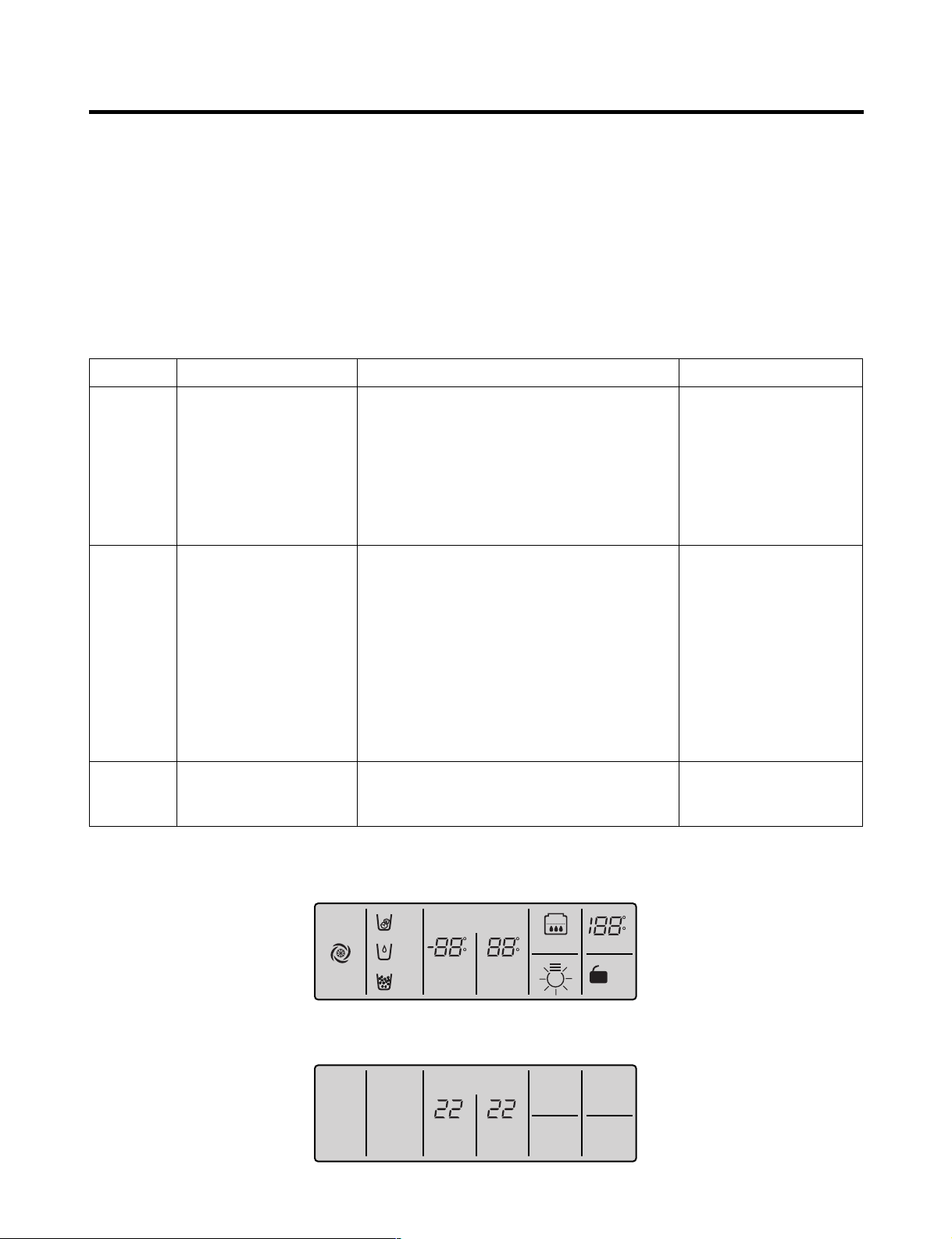
GR-L267BV(T)RA, GR-L267BV(T,S)PA :
Except for (A)22 (B)22 LEDs
GR-L267BV(T)R : Except for only middle
Notch Bar Graphics
Return to the initial status.
Freezing fan turns off in
door opening.
Return to the normal mode
when the defrost sensor is
above +5°C
Compressor will operate
after delay for 7 minutes
TEST MODE1 STATUS DISPLAY
TEST MODE2 STATUS DISPLAY
- 27 -
Page 28

MICOM FUNCTION
2-18. Function of dispenser and water dispenser built-in
1. This is function allowing ice and water to come outside without opening door.
2. If pressing the dispenser switch (rubber button) after selecting ice (cube ice, crushed ice) or water, ice and water
equivalent to each come out. However, the duct doors are opened by electrical solenoid valve (Duct Door Solenoid) if
pressing the press switch in case of selecting ICE. If pressing the dispenser press switch and then detaching the hands,
the duct door is closed after it is opened for 5 seconds.
3. Function allowing ice and water to come stops if freezing room doors are opened.
4. If there is no Off signal even when 3 minutes have passed while pressing the dispenser press switch after selecting ice
(cube ice, crushed ice) or water, geared motor and solenoid (Cube, Water) is automatically turned off. However, the
solenoid (duct door) is stop 5 seconds after Off (to prevent short-circuit of a coil due to overheat of solenoid).
5. Dispenser Lamp On/Off function
Lamp on the dispenser part is turned on if pressing the dispenser press switch after selecting ice (cube ice, crushed ice)
or water. If detaching the hands, it is turned off.
6. Selection function of water/crushed/ cube ice
1) This is function to allow selection of water/crushed/ cube ice function depending on user’s selection. Display and
selection is done if pressing the dispenser selection button.
2) In the initial Power On, cube ice is automatically selected.
3) In selecting cube ice, geared motor is operated so that crushed ice can be supplied outside if pressing the press switch
when ice is formed in the ice storage container (Bank, Ice).
4) In selecting cube ice, geared motor is operated so that cube ice can be supplied outside if pressing the press switch
when ice is formed in the ice storage container (Bank, Ice).
7. Water dispenser function
1) It is displayed for selection if user selects water at the function adjustment part.
2) Water dispenser function is a type directly connected to a water pipe. The water solenoid valve built-in at the right side
of the Back plate is opened so that water can be supplied if selecting Water from the function adjustment part and then
pressing the press switch.
- 28 -
Page 29
EXPLANATION FOR MICOM CIRCUIT
1. Explanation for PWB circuit
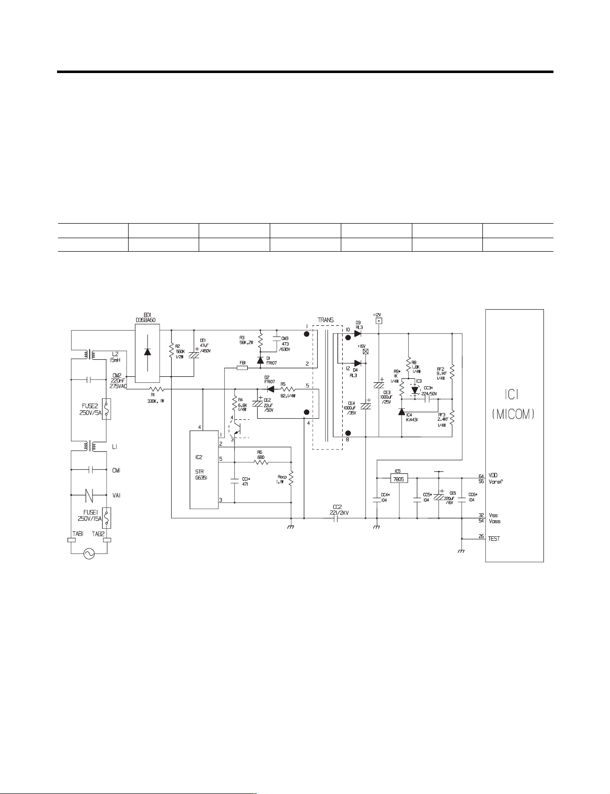
1-1. Power circuit
The power circuit includes a Switched Mode Power Supply (SMPS). It consists of a rectifier (BD1 and CE1) converting AC
to DC, a switch (IC2) switching the DC voltage, a transformer, and a feedback circuit (IC3 and IC4).
Caution : Since high voltage (160 Vdc) is maintained at the power terminal, wait at least 3 minutes after unplugging the
appliance to check the voltages to allow the current to dissipate.
Voltage of every part is as follows:
Part VA1 CE1 CE2 CE3 CE4 CE5
Voltage 120 Vac 160 Vdc 14 Vdc 12 Vdc 15.5 Vdc 5 Vdc
(1) GR-L267BV(T)R
- 29 -
Page 30
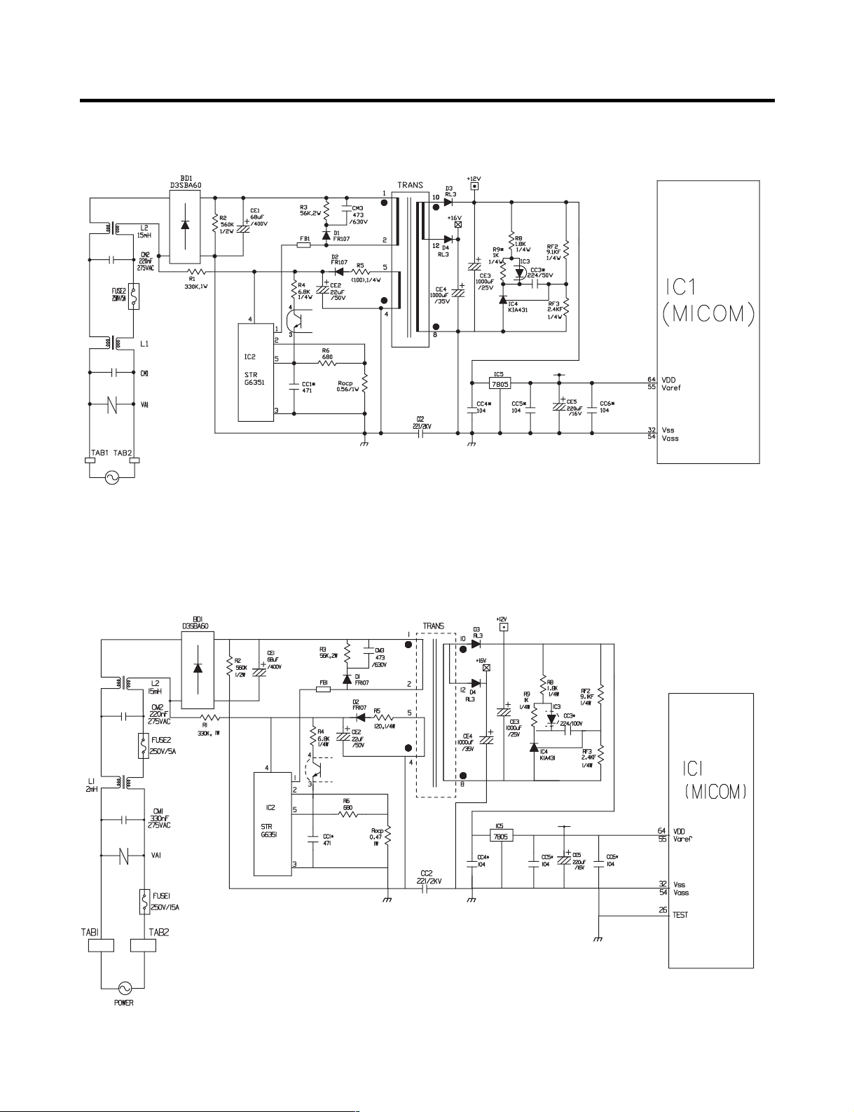
(2) GR-L267BV(T)RA
(3) GR-L267BV(T,S)PA
- 30 -
Page 31

EXPLANATION FOR MICOM CIRCUIT
1-2. Oscillation circuit
The oscillation circuit generates a basic clock signal for synchronization and time calculation related to the transmission of
data and calculations made by the MICOM (IC1). The oscillator (OSC1) must always be replaced with an exact rated part,
because if this spec is changes, the time calculations of the MICOM will be affected and it might not work at all.
(1) GR-L267BV(T)R
(2) GR-L267BV(T)RA
(3) GR-L267BV(T,S)PA
- 31 -
Page 32

1-3. Reset circuit
The RESET circuit allows various parts of the MICOM, such as RAM, defrosting, etc., to be restarted from the initial state
when power is interrupted or restored. A LOW signal applied to the reset terminal for 10 ms causes the MICOM to reset
itself. During normal operation, the voltage at the reset terminal is 5 Vdc. If the reset fails, the MICOM will not operate.
(1) GR-L267BV(T)R
(2) GR-L267BV(T)RA
(3) GR-L267BV(T,S)PA
- 32 -
Page 33

EXPLANATION FOR MICOM CIRCUIT
1-4. Load/dispenser operation, door opening circuit
1. LOAD DRIVING CIRCUIT
✽ The fan operates at the regular speed even if the door of the refrigerator or freezer is opened. When the doors are closed,
the fan reverts to its original speed.
✽ (A), (B), (C), and (D) of door switch for the freezer or refrigerator are connected to the door open sensing circuit in parallel
toward both ends of switch to determine door open at MICOM.
✽ In the TEST mode, the fan will stop if any door is opened. It will resume operation when the door is closed.
Type of Load Compressor
Measuring part (IC6) IC6-16 IC6-13 IC6-12 IC6-15 IC6-14
Status
ON Within 1 V
OFF 12 V
Frost Removal
Heater
AC Converting
Relay
Refrigerator
LAMP
Dispensor
Heater
(1) GR-L267BV(T)R
- 33 -
Page 34

EXPLANATION FOR MICOM CIRCUIT
(2) GR-L267BV(T)RA
(3) GR-L267BV(T,S)PA
Type of Load Compressor
Measuring part (IC6) IC6-15 IC6-11 IC6-10 IC6-14 IC6-12
Status
ON Within 1 V
OFF 12 V
Frost Removal
Heater
AC Converting
Relay
Refrigerator
LAMP
Dispensor
Heater
- 34 -
Page 35

EXPLANATION FOR MICOM CIRCUIT
2. Dispenser operation circuit
(1) GR-L267BV(T)R
1) Check load driving status
Type of Load
Measuring part IC6-11 IC6-10 IC7-15 IC7-13
Status
2) Lever Switch sensing circuit
Measuring part
Lever S/W
On(Press)
OFF 5V
ON Within 1 V
OFF 12 V
GEARED
MOTOR
5 V
0 V
SOLENOID
CUBE
IC1(Micom) (No. 16)
WATER VALVE
WATER
(60 Hz)
SOLENOID
DISPENSER
- 35 -
Page 36

EXPLANATION FOR MICOM CIRCUIT
(2) GR-L267BV(T)RA
1) Check load driving status
Type of Load
Measuring part IC6-11 IC6-10 IC7-15 IC7-13
Status
2) Lever Switch sensing circuit
Measuring part
Lever S/W
On(Press)
OFF 5V
ON Within 1 V
OFF 12 V
GEARED
MOTOR
5 V
0 V
SOLENOID
CUBE
IC1(Micom) (No. 16)
WATER VALVE
WATER
(60 Hz)
SOLENOID
DISPENSER
- 36 -
Page 37

EXPLANATION FOR MICOM CIRCUIT
(3) GR-L267BV(T,S)PA
1) Check load driving status
Type of Load
Measuring part IC7-20 IC7-19 IC7-17 IC7-15
Status
2) Lever Switch sensing circuit
Measuring part
Lever S/W
On(Press)
OFF 5V
ON Within 1 V
OFF 12 V
GEARED
MOTOR
5 V
0 V
SOLENOID
CUBE
IC1(Micom) (No. 16)
WATER VALVE
WATER
(60 Hz)
DISPENSER
- 37 -
SOLENOID
Page 38

EXPLANATION FOR MICOM CIRCUIT
3. Door opening sensing circuit
(1) GR-L267BV(T)R
(2) GR-L267BV(T)RA
(3) GR-L267BV(T,S)PA
Measuring part
Door of Freezer / Refrigerator
Closing 5 V ( A - B , C - D . Switch at both ends are at Off status)
Opening 0 V ( A - B , C - D . Switch at both ends are at On status)
✽ Since door switches (A) and (B) are interconnected, if either fails, the other will not respond properly.
✽ If either switch fails, the light will not come on.
IC1 (MICOM) No. (44, 45) / (45, 46) / (47, 48) Pin
- 38 -
Page 39

EXPLANATION FOR MICOM CIRCUIT
E
F
A
B
D
C
A
B
C
D
F
E
RW1
10KF
CE18
R73
CC32
1-5. Temperature sensing circuit
(1) GR-L267BV(T)R
(2) GR-L267BV(T)RA
- 39 -
Page 40

EXPLANATION FOR MICOM CIRCUIT
E
F
B
A
D
G
C
(3) GR-L267BV(T,S)PA
The circuits involving the freezer and refrigerator sensors controls the temperature in both the freezer and the refrigerator.
The Icemaker sensor detects when ice is made. The defrost sensor determines both the need for defrosting and the
efficiency of the defrost operation. See the table below for voltages and checkpoints.
SENSOR CHECK POINT
Freezing sensor POINT A Voltage
Defrost sensor POINT B Voltage
Refrigerator sensor 1 POINT C Voltage
Refrigerator sensor 2 POINT D Voltage 0.5 V~4.5 V 0 V 5 V
Room temperature sensor POINT E Voltage
Water tank sensor POINT F Voltage
Optichill sensor POINT G Voltage
NORMAL(-30 °C ~ 50 °C) IN
SHORT IN OPEN
- 40 -
Page 41

EXPLANATION FOR MICOM CIRCUIT
1-6. Switch entry circuit
The following circuits are sensing signal form the test switch, damper motor reed switch for testing and diagnosing the
refrigerator.
(1) GR-L267BV(T)R
(2) GR-L267BV(T)RA
(3) GR-L267BV(T,S)PA
- 41 -
Page 42

EXPLANATION FOR MICOM CIRCUIT
1-7. Option designation circuit (model separation function)
(1) GR-L267BV(T)RA
(2) GR-L267BV(T,S)PA
The circuits shown above vary according to which features are included on your particular model.
uThese circuits are preset at the factory and cannot be altered.
NOTE: The chart makes absolutely no sense. You have Optichill no matter which way the connection is set.
Separation Connection Status Application Standard
OP1
Connection OptiChill exist
OUT OptiChill don’t exist
- 42 -
Page 43

EXPLANATION FOR MICOM CIRCUIT
1-8. Stepping motor operation circuit
(1) GR-L267BV(T)R
(2) GR-L267BV(T)RA
(3) GR-L267BV(T,S)PA
- 43 -
Page 44

EXPLANATION FOR MICOM CIRCUIT
INA
INB
A
B
A
B
CCW (Reverse rotation) (Positive rotation) CW
The motor is driven by magnetism formed in the areas of the coils and the stator. Rotation begins when a HIGH signal is
applied to MICOM Pin 33 of IC10 (TA7774F). This causes an output of HIGH and LOW signals on MICOM pins 34 and 35.
Explanation) The stepping motor is driven by sending signals of 3.33 mSEC via MICOM pins 33, 34, and 35, as shown in
the chart below. These signals are output via terminals 10, 11, 14, and 15 via input terminals 3, 6, and 8 of
IC10 (TA7774F), the motor drive chip. The output signals allow the coils wound on each phase of the stator to
form a magnetic field, which causes rotation. Input to the terminals INA and INB of IC10 as shown in the chart
below drives the motor.
- 44 -
Page 45

EXPLANATION FOR MICOM CIRCUIT
1-9. Fan motor driving circuit (freezer, mechanical area)
1. The circuit cuts all power to the fan drive IC, resulting in a standby mode.
2. This circuit changes the speed of the fan motor by varying the DC voltage between 7.5 Vdc and 16 Vdc.
3. This circuit stops the fan motor by cutting off power to the fan when it senses a lock-up condition.
a , d part b part e part
Motor OFF 5V 2V or less 2V or less
Motor ON 2 ~ 3V 12 ~ 14V 8 ~ 16V
(1) GR-L267BV(T)R
b
a
e
d
- 45 -
Page 46

EXPLANATION FOR MICOM CIRCUIT
a
b
d
e
b
a
d
e
(2) GR-L267BV(T)RA
(3) GR-L267BV(T,S)PA
- 46 -
Page 47

EXPLANATION FOR MICOM CIRCUIT
Temperature compensation at refrigerator
Temperature compensation at freezer
Temperature compensation at refrigerator
Temperature compensation at freezer
1-10. Temperature compensation and temperature compensation circuit
1. Temperature compensation in freezer and refrigerator
(1) GR-L267BV(T)R (2) GR-L267BV(T)RA
(3) GR-L267BV(T,S)PA
Freezer Refrigerator
Resistance value Temperature Resistance value Temperature Remarks
(RCF1) compensation (RCR1) compensation
180 kΩ +5 °C [+9°F] 180 kΩ +2.5 °C [+4.5°F] Warmer
56 kΩ +4 °C [+7.2°F] 56 kΩ +2.0 °C [+3.6°F]
33 kΩ +3 °C [+5.4°F] 33 kΩ +1.5 °C [+2.7°F]
18 kΩ +2 °C [+3.6°F] 18 kΩ +1.0 °C [+1.8°F]
12 kΩ +1 °C [+1.8°F] 12 kΩ +0.5 °C [+0.9°F]
10 kΩ 0 °C [0°F] 10 kΩ 0 °C [0°F]
8.2 kΩ -1 °C [-1.8°F] 8.2 kΩ -0.5 °C [-0.9°F]
5.6 kΩ -2 °C [-3.6°F] 5.6 kΩ -1.0 °C [-1.8°F]
3.3 kΩ -3 °C [-5.4°F] 3.3 kΩ -1.5 °C [-2.7°F]
2 kΩ -4 °C [-7.2°F] 2 kΩ -2.0 °C [-3.6°F]
470 Ω -5 °C [-9°F] 470 Ω -2.5 °C [-4.5°F] Cooler
u Temperature compensation table by adjustment value (difference value against current temperature)
Ex) If you change compensation resistance at a refrigerator (RCR1) from 10 kΩ (current resistance) to 18 kΩ (modified
resistance), the temperature at the cold storage will increase by +1°C[+1.8°F].
Reference temperature
- 47 -
Page 48

EXPLANATION FOR MICOM CIRCUIT
u Temperature compensation table at the refrigerator is as follows:
Modification
resistance
Current
resistance
470Ω [0.9 °F] [1.8 °F] [2.7 °F] [3.6 °F] [4.5 °F] [5.4 °F] [6.3 °F] [7.2 °F] [8.1 °F] [9 °F]
2 kΩ [0.9 °F] [0.9 °F] [1.8 °F] [2.7 °F] [3.6 °F] [4.5 °F] [5.4 °F] [6.3 °F] [7.2 °F] [8.1 °F]
3.3 kΩ [1.8 °F] [0.9 °F] [0.9 °F] [1.8 °F] [2.7 °F] [3.6 °F] [4.5 °F] [5.4 °F] [6.3 °F] [7.2 °F]
5.6 kΩ [2.7 °F] [1.8 °F] [0.9 °F] [0.9 °F] [1.8 °F] [2.7 °F] [3.6 °F] [4.5 °F] [5.4 °F] [6.3 °F]
8.2 kΩ [3.6 °F] [2.7 °F] [1.8 °F] [0.9 °F] [0.9 °F] [1.8 °F] [2.7 °F] [3.6 °F] [4.5 °F] [5.4 °F]
Refrigerator
470 Ω 2 kΩ 3.3 kΩ 5.6 kΩ 8.2 kΩ 10 kΩ 12 kΩ 18 kΩ 33 kΩ 56 kΩ 180 kΩ
No 0.5 °C1 °C 1.5 °C2 °C 2.5 °C3 °C 3.5 °C4 °C 4.5 °C5 °C
change
0.5 °C No 0.5 °C1 °C 1.5 °C2 °C 2.5 °C3 °C 3.5 °C4 °C 4.5 °C
Down change
1 °C 0.5 °C No 0.5 °C1 °C 1.5 °C2 °C 2.5 °C3 °C 3.5 °C4 °C
Down
1.5 °C1 °C 0.5 °C No 0.5 °C1 °C 1.5 °C2 °C 2.5 °C3 °C 3.5 °C
Down Down Down
2 °C 1.5 °C1 °C 0.5 ° No 0.5 °C1 °C 1.5 °C2 °C 2.5 °C3 °C
Down Down Down
Up Up Up Up Up Up Up Up Up Up
Up Up Up Up Up Up Up Up Up
Down
change
Up Up Up Up Up Up Up Up
change
Drop
Up Up Up Up Up Up Up
change
Up Up Up Up Up Up
(RCR1) 2.5 °C2 °C 1.5 °C1 °C 0.5 °C No 0.5 °C1 °C 1.5 °C2 °C 2.5 °C
10 kΩ [4.5 °F] [3.6 °F] [2.7 °F] [1.8 °F] [0.9 °F] [0.9 °F] [1.8 °F] [2.7 °F] [3.6 °F] [4.5 °F]
Down Down Down Down Down
3 °C 2.5 °C2 °C 1.5 °C1 °C 0.5 °C No 0.5 °C1 °C 1.5 °C2 °C
12 kΩ [5.4 °F] [4.5 °F] [3.6 °F] [2.7 °F] [1.8 °F] [0.9 °F] [0.9 °F] [1.8 °F] [2.7 °F] [3.6 °F]
Down Down Down Down Down Down
3.5 °C3 °C 2.5 °C2 °C 1.5 °C1 °C 0.5 °C No 0.5 °C1 °C 1.5 °C
18 kΩ [6.3 °F] [5.4 °F] [4.5 °F] [3.6 °F] [2.7 °F] [1.8 °F] [0.9 °F] [0.9 °F] [1.8 °F] [2.7 °F]
Down Down Down Down Down Down Down
4 °C 3.5 °C3 °C 2.5 °C2 °C 1.5 °C1 °C 0.5 °C No 0.5 °C1 °C
33 kΩ [7.2 °F] [6.3 °F] [5.4 °F] [4.5 °F] [3.6 °F] [2.7 °F] [1.8 °F] [0.9 °F] [0.9 °F] [1.8 °F]
Down Down Down Down Down Down Down Down
4.5 °C4 °C 3.5 °C3 °C 2.5 °C2 °C 1.5 °C1 °C 0.5 °C No 0.5 °C
56 kΩ [8.1 °F] [7.2 °F] [6.3 °F] [5.4 °F] [4.5 °F] [3.6 °F] [2.7 °F] [1.8 °F] [0.9 °F] [0.9 °F]
Down Down Down Down Down Down Down Down Down
5 °C 4.5 °C4 °C 3.5 °C3 °C 2.5 °C2 °C 1.5 °C1 °C 0.5 °CNo
180 kΩ [9 °F] [8.1 °F] [7.2 °F] [6.3 °F] [5.4 °F] [4.5 °F] [3.6 °F] [2.7 °F] [1.8 °F] [0.9 °F]
Down Down Down Down Down Down Down Down Down Down
u Temperature compensation at the freezer is performed the same as at the refrigerator. The value for the freezer is twice
that of the refrigerator.
u This circuit enters the necessary level of temperature compensation for adjusting the appliance. The method is the same
for every model in this appliance family.
change
Up Up Up Up Up
change
Up Up Up Up
change
Up Up Up
change
Up Up
change
Up
change
- 48 -
Page 49

EXPLANATION FOR MICOM CIRCUIT
2. Compensation circuit for temperature at freezer
(1) GR-L267BV(T)RA (2) GR-L267BV(T,S)PA
Temperature compensation in CUT
JCR1 +1 °C [+1.8 °F]
JCR2 +1 °C [+1.8 °F]
JCR3 -1 °C [-1.8 °F]
JCR4 -1 °C [-1.8 °F]
+2 °C [+3.6 °F]
-2 °C [-3.6 °F]
Compensation Compensation
for weak-cold for over-cold
JCR3 JCR4 JCR1 JCR2
CUT -1 °C [-1.8 °F]
CUT -1 °C [-1.8 °F]
CUT +1 °C [+1.8 °F]
CUT +1 °C [+1.8 °F]
CUT CUT -2 °C [-3.6 °F]
CUT CUT +2 °C [+3.6 °F]
CUT CUT 0 °C [0 °F]
CUT CUT 0 °C [0 °F]
CUT CUT 0 °C [0 °F]
CUT CUT 0 °C [0 °F]
CUT CUT CUT -1 °C [-1.8 °F]
CUT CUT CUT +1 °C [+1.8 °F]
CUT CUT CUT CUT 0 °C [0 °F]
Temperature compensation value
at refrigerator
0 °C (In shipment from factory)
Remarks
u This circuit allows adjustment of the set temperature for compensation by changing jumpers at locations JCR1~JCR4.
- 49 -
Page 50

EXPLANATION FOR MICOM CIRCUIT
EXPRESS
FRZ
ON
CUBE
LOCK
DISPENSER
BUTTON
WATER
CRUSH
3 SECS
DIGITAL CONTROL
FRZ TEMP REF TEMP
COLDEST
COLD
FILTER RESET
HOLD 3SECS
FILTER
Main MICOM LCD(LED) dedicated MICOM
DC 12V
GND
Transmission (error status)
Reception (notch status)
Main PCB L/Wire FD/H(4-wires) Display PCB
1-11. Communication circuit and connection L/Wire between main PCB and display PCB
The following communication circuit is used for exchanging information between the main MICOM of the Main PCB and the
dedicated MICOM of the LED (LCD) Display PCB.
A bi-directional lead wire assembly between the two boards is required for the display to function properly.
Poor communication occurs if a continuous information exchange fail to continue for more than 2 minutes between main
MICOM of main PCB and LCD (LED) dedicated MICOM for LCD (LED) control of display PCB.
(1) GR-L267BV(T)R
- 50 -
Page 51

EXPLANATION FOR MICOM CIRCUIT
EXPRESS
FRZ
ON
CUBE
ROOM TEMPERATURE
LOCK
DISPENSER & BUTTON
F
WATER
CRUSH
C
3 SECS
DIGITAL CONTROL
FRZ TEMP
F
C
F
C
REF TEMP
FILTER RESET
HOLD 3SECS
FILTER
EXPRESS
JET
CUBE
ROOM TEMPERATURE
LOCK
DISPENSER & BUTTON
F
WATER
CRUSH
C
3 SECS
DIGITAL CONTROL
FRZ TEMP
F
C
F
C
REF TEMP
FILTER RESET
HOLD 3SECS
FILTER
(2) GR-L267BV(T)RA
(3) GR-L267BV(T,S)PA
- 51 -
Page 52

EXPLANATION FOR MICOM CIRCUIT
2) Sensor resistance characteristics table
Measuring Temperature (°C) Freezing Sensor
-20 °C 22.3 kΩ 77 kΩ
-15 °C 16.9 kΩ 60 kΩ
-15 °C 13.0 kΩ 47.3 kΩ
-5 °C 10.1 kΩ 38.4 kΩ
0 °C 7.8 kΩ 30 kΩ
+5 °C 6.2 kΩ 24.1 kΩ
+10 °C 4.9 kΩ 19.5 kΩ
+15 °C 3.9 kΩ 15.9 kΩ
+20 °C 3.1 kΩ 13 kΩ
+25 °C 2.5 kΩ 11 kΩ
+30 °C 2.0 kΩ 8.9 kΩ
+40 °C 1.4 kΩ 6.2 kΩ
+50 °C 0.8 kΩ 4.3 kΩ
Cold storage sensor 1&2
Frost removal sensor, Outside sensor
u Resistance value allowance of sensor is ±5%.
u When measuring the resistance value of the sensor, allow the temperature of that sensor to stabilize for at least 3 minutes
before measuring. This delay is necessary because of the sense speed relationship.
u Use a digital tester to measure the resistance. An analog tester has to great a margin of error.
u Resistance of the cold storage sensor 1 and 2 shall be measured with a digital tester after separating CON8 of the PWB
ASSEMBLY and the MAIN part.
u Resistance of the freezing sensor shall be measured with a digital tester after separating CON7 of the PWB ASSEMBLY
and the MAIN part.
- 52 -
Page 53

EXPLANATION FOR MICOM CIRCUIT
1-12. OptiChill stepping MOTOR/Display
(1) GR-L267BV(T,S)PA
1-13. Jet freezing
(1) GR-L267BV(T,S)PA
- 53 -
Page 54

EXPLANATION FOR MICOM CIRCUIT
2. PWB parts diagram and list
2-1. PWB Assembly, main part diagram
(1) GR-L267BV(T)R
- 54 -
Page 55

EXPLANATION FOR MICOM CIRCUIT
(2) GR-L267BV(T)RA
- 55 -
Page 56

EXPLANATION FOR MICOM CIRCUIT
(3) GR-L267BV(T,S)PA
- 56 -
Page 57

EXPLANATION FOR MICOM CIRCUIT
2-2. Parts list
(1) GR-L267BV(T)R
- 57 -
Page 58

EXPLANATION FOR MICOM CIRCUIT
- 58 -
Page 59

EXPLANATION FOR MICOM CIRCUIT
(2) GR-L267BV(T)RA
- 59 -
Page 60

EXPLANATION FOR MICOM CIRCUIT
- 60 -
Page 61

EXPLANATION FOR MICOM CIRCUIT
(3) GR-L267BV(T,S)PA
- 61 -
Page 62

EXPLANATION FOR MICOM CIRCUIT
- 62 -
Page 63

EXPLANATION FOR MICOM CIRCUIT
4
APPLICATION
No
P/NO
-
-
1
1
2
3
-
-
1
-
6870JB8189A
DESCRIPTION
REFLECTOR
PWB(PCB)
A WORK
CHD-PJT BETTER HIPS
SPEC
BETTER1
IL SAN
DAEDUCK
MAKER REMARK
-
FR1(STH)
CONNECTOR (CIRC),WAFER
NAME PLATE,P(H)
13
616
15
14
6600RRT002J SWITCH,TACT
6630JB8004J
4140JB1045A
-
-
-
-
44
11
12
10
9
1
-
-
1
8
7
6
5
JPT1138A JEIL 12VDC 50MA SMD
SMAW250-10
03 CH-PJT QF/JET MODULE USA
6
-
0DSRM00068A DIODE,SWITCHING
0DLLE0048AA LED ULTRA YELLOW GREEN
JEIL SW101..106
YEON HO
SEOUL
CON101
-
-
-
-
-
-
-
-
ROHM D101..106
LEDTECH L101..144
CHD-PJT BETTER1 MODULE DISPLAY
RLS4148 ROHM R/TP LLDS(LL-34) 75V 200MA
CHD-PJT
Qty
SW101(QF) SW102(S) SW105(FC)SW104(R) SW106(LOCK)SW103(F)
2-3. DISPLAY ASSEMBLY part diagram
(1) GR-L267BV(T)R
- 63 -
Page 64

(2) GR-L267BV(T)RA, GR-L267BV(T,S)PA
- 64 -
Page 65

2-4. DISPLAY circuit diagram
SW102 SW105
L115,116
( )
D105
L117,118 L119,120
( )
SW104
D104D101
(Lamp)
SW103
L139..142L125..128
SW101 SW106
(?ON)
L113,114
(})
L121..124
( )
(D0)(<)
L133,134
1N4148X6
L111,112
L135..138
D102
(
}/ )
(
/)
D106D103
(})
L101,102
(
)
L103,104
( }/ )
L107,108
( /
)
L143,144
(?ON)
( )
L109,110L105,106
10
9
8
7
6
5
4
3
2
1
L129..132
(p )
(1) GR-L267BV(T)R
- 65 -
Page 66

EXPLANATION FOR MICOM CIRCUIT
(2) GR-L267BV(T)RA, GR-L267BV(T,S)PA
- 66 -
Page 67

EXPLANATION FOR MICOM CIRCUIT
3. PWB Circuit Diagram may vary according to model.
(1) GR-L267BV(T)R
- 67 -
Page 68

EXPLANATION FOR MICOM CIRCUIT
- 68 -
Page 69

(2) GR-L267BV(T)RA
- 69 -
Page 70

- 70 -
Page 71

(3) GR-L267BV(T,S)PA
- 71 -
Page 72

- 72 -
Page 73

ICE MAKER AND DISPENSER WORKING PRINCIPLES AND REPAIR
• Level Ice Maker Cube Mould for “Initial Control”
after power is input.
Power Input
Initial Control
Ice Making Control
Ice Ejection Control
Water Supply Control
Test Control
• Wait until the water in the cube mould is frozen
after ice maker starts operation.
• Check ice bank is full of ice by rotating ice ejection
motor in normal and reverse direction and eject ice into
the ice bank if ice bank is not full.
• This is for refrigerator assembly line and service. When “ice making test switch” is pressed,
it operates in the following steps: initial ice ejection water supply control steps.
• Conduct “Ice Making Control” after supplying water into the ice maker
cube mould by operating water valve.
1. Working Principles
1-1. Ice Maker Working Principles
1-2. Dispenser Working Principles
1. This function is available in Model GR-L267BV(T)R, GR-L267BV(T)RA, GR-L267BV(T,S)PA where water and ice are
available without opening freezer compartment door.
2. “Crushed Ice” is automatically selected when power is initially applied or reapplied after power cut.
3. When dispenser selection switch is continuously pressed, light is on in the following sequence:
“Water” → “Cube Ice” → “Crushed Ice”.
4. Lamp is on when dispenser rubber button is pressed and vice versa.
5. When dispenser crushed ice rubber button is pressed, dispenser solenoid and geared motor work so that crushed ice can
be dispensed if there is ice in the ice bank.
6. When dispenser cube ice rubber button is pressed, dispenser solenoid, cube ice solenoid and geared motor work so that
cube ice can be dispensed if there is ice in the ice bank.
7. When dispenser water rubber button is pressed, water valve opens and water is supplied if water valve is normally
installed on the right side of the machine room.
8. Ice and water are not available when freezer door is open.
- 73 -
Page 74

ICE MAKER AND DISPENSER WORKING PRINCIPLES AND REPAIR
2. Function of Ice Maker
2-1. Initial Control Function
1. When power is initially applied or reapplied after power cut, it detects level of ice maker cube mould after completion of
MICOM initialization. The detecting lever moves up and down.
2. The level of ice maker cube mould is judged by output signal, high and low signal, of Hall IC. Make the cube mould to be
horizontal by rotating ice ejection motor in normal or reverse direction so that High/Low signal can be applied to MICOM
Pin No. 42.
3. If there is no change in signals one minute after the geared motor starts to operate, it stops icemaker operation and check
the signal every hour. It resets initialization of icemaker when it becomes normal.
4. It judges that the initial control is completed when it judges the ice maker cube mould is horizontal.
5. Ice ejection conducts for 1 cycle irrespect of ice in the ice bank when power is initially applied.
2-2. Water Supply Control Function
1. This is to supply water into the ice maker cube mould by operating water valve in the machine room when ice ejection
control is completed and ice maker mould is even.
2. The quantity of water supplied is determined by DIP switch and time.
<Water Supply Quantity Table>
REMARKS
supplied depends on DIP
switch setting conditions
and water pressure as it
is a direct tap water
connection type. (the
water supplied is
generally 80 cc to 120 cc)
PWB.
No
1
2
3
4
5
6
7
8
GR-L267BV(T)R GR-L267BV(T)RA, GR-L267BV(T,S)PA
DIP SWITCH SETTING
S1 S2
OFF OFF 6.5 SEC
ON OFF 5.5 SEC
OFF ON 7.5 SEC
ON ON 8.5 SEC
WATER
SUPPLY TIME
DIP SWITCH SETTING
S1 S2 S3
OFF OFF OFF 6.5 SEC
ON OFF OFF 5.5 SEC
OFF ON OFF 6 SEC
ON ON OFF 7 SEC
OFF OFF ON 7.5 SEC
ON OFF ON 8 SEC
OFF ON ON 9 SEC
ON ON ON 10 SEC
WATER
SUPPLY TIME
* The quantity of water
* DIP switch is on the main
3. If water supply quantity setting is changed while power is on, water supplies for the amended time. If DIP switch is
changed during water supply, water shall be supplied for the previous setting time. But it will supply for the amended time
from the next supply.
4. When water supply signal is applied to water and ice valves at the same time during water supply, water shall be supplied
to water valve. If water supply signal is applied to ice valve during water supply, water shall be supplied to both water and
ice valves.
2-3. Ice Making Control Function
1. Ice making control is carried out from the completion of water supply to the completion of ice making in the cube mould.
Ice making sensor detects the temperature of cube mould and completes ice making. (ice making sensor is fixed below
ice maker cube mould)
2. Ice making control starts after completion of water supply control or initial control.
3. It is judged that ice making is completed when ice making sensor temperature reaches at -8°C after 100 minutes when
water is supplied to ice maker cube mould.
4. It is judged that ice making is completed when ice maker sensor temperature reaches below -12 °C after 20 minutes in
condition 3.
- 74 -
Page 75

ICE MAKER AND DISPENSER WORKING PRINCIPLES AND REPAIR
Bank is
not full
HALL IC
OUTPUT
SIGNALS
Bank is
full
HALL IC
OUTPUT
SIGNALS
ICE CHECKING
AXIS
ICE CHECKING LEVEL 30°
Maximum tilting
point
Ice making
(Original point)
Lock
2±1 sec
9±3 sec
8±3 sec
Ice Checking Ice Ejection
Lock
Horizontal
Conditions
Level Retrun
Conditions
2-4. Ice Ejection Control Function
1. This is to eject ice from ice maker cube mould after ice making is completed.
2. If Hall IC signal is on within 3.6 seconds after ice ejection motor rotates in normal direction, it does not proceed ice
ejection but waits. If the ice bank is full, ice ejection motor rotates in normal direction in every hour to check the condition
of ice bank. If the ice bank is not full, the water supply control starts after completion of ice ejection control. If the ice bank
is full, ice ejection motor rotates in reverse direction and sops under ice making or waiting conditions.
3. If ice bank is not full, ice ejection starts. The cube mould tilts to the maximum and ice is separated from the mould and ice
checking lever raises.
4. Ice ejection motor stops for 1 second if Hall IC signal changes from OFF (low) to ON (high) after 3.6 seconds when ice
ejection motor rotates in normal direction. If there is no change in Hall IC signals within 1 minute after ice ejection motor
operates, ice ejection motor stops as ice ejection motor or hall IC is out of order.
5. If ice ejection motor or Hall IC is abnormal, ice ejection motor rotates in normal direction to exercise initial operation. It
resets the ice maker if ice ejection motor or Hall IC is normal.
6. The mould stops for 1 second at maximum tilted conditions.
7. The mould returns to horizontal conditions as ice ejection motor rotates in reverse direction.
8. When the mould becomes horizontal, the cycle starts to repeat:
Water Supply → Ice Making → Ice Ejection → Mould Returns to Horizontal
- 75 -
Page 76

ICE MAKER AND DISPENSER WORKING PRINCIPLES AND REPAIR
2-5 Test Function
1. It is to force the operation during operation test, service, and cleaning. The test switch is mounted under the automatic
ice maker. The test function starts when the test switch is pressed for more than 0.5 second.
2. Test button does not work during ice ejection and water supply. It works when it is in the horizontal conditions. If mould is
full of ice during test function operation, ice ejection control and water supply control do not work.
3. When test switch is pressed for more than 0.5 second in the horizontal conditions, ice ejection starts irrespect of the
mould conditions. Water shall be splashed if test switch is pressed before the water in the mould freezes. Water shall be
supplied while the mould returns to the horizontal conditions after ice ejection. Therefore the problems of ice ejection,
returning to the horizontal conditions, and water supply can be checked by test switch. When test function performs
normally, buzzer sounds and water supply shall carry out. Check it for repair if buzzer does not sound.
4. When water supply is completed, the cycle operates normally as follows: Ice making → Ice ejection → Returning to
horizontal conditions → Water supply
5. Remove ice from the ice maker cube mould and press test switch when ice maker cube mould is full of ice as ice ejection
and water supply control do not work when cube mould is full of ice.
2-6. Other functions relating to freezer compartment door opening
1. When freezer door is open, ice dispenser stops in order to reduce noise and ice drop.
2. When freezer door is open during ice ejection and cube mould returning to horizontal condition, ice ejection and cube
mould level return proceed.
3. When freezer door is open, geared motor and cube ice solenoid immediately stop and duct door solenoid stops after 5
seconds.
4. Water dispenser stops in order to protect water drop when freezer door is open.
5. Test function operates normally irrespect of refrigearator compartment door opening.
- 76 -
Page 77

ICE MAKER AND DISPENSER WORKING PRINCIPLES AND REPAIR
No
Yes
Yes
Yes
No
No
No
No
Yes
Yes
Is DC Power (5V and 12V)
output normal?
Failed DC Power
• Check DC power (5V, 12V).
Change main PWB
Is cube ice LCD off during
troubleshooting check?
Failed ice making sensor
• Check the resistance of
both ends (1,2) of ice making
sensor of CON9.
• Defects between ice making
sensor and board
(Pin No. 60 of IC1)
Replace Ice making
Sensor
Is Crushed Ice LCD off during
troubleshooting check?
Failed Ice Maker Unit
• Is the resistance of both ends
(9,10) of ice ejection motor of
CON9 between 18 and 22Ω?
• Is ice ejection motor drive circuit
(IC11 and peripheral circuits)
normal?
• Defects between Hall IC and
Board (Pin No. 42 of IC1).
• Confirm ice ejection and level
return when pressing
test switch.
Replace Ice Maker Unit
Replace Main PWB
Are ice
ejection and level return
normal when test switch is
pressed for more than 0.5 second?
Does the bell
sound once?
Failed ice maker unit test switch
• Are both ends (5,6) of CON9
test switch open?
• Defects between test switch
and board (Pin No. 38 of IC1).
• Are both ends (3,4) of CON9
ice maker stop switch short?
Replace Ice maker Unit
Replace water
supply valve
• Is power applied to water
supply valve?
• Does the water supply
valve work normally?
• Is the water supply line
normally connected?
Poor water supply
Is water suppy normal
after Ice ejection and level return
by ice ejection motor?
Normal
3. Ice Maker Troubleshooting
* Troubleshooting: it is possible to confirm by pressing freezer and refrigerator temperature control buttons for more
than 1 second. (ice maker is normal if all leds are on): refer to trouble diagnposis function in MICOM
function 2-8 (page 21)
- 77 -
Page 78

ICE MAKER AND DISPENSER WORKING PRINCIPLES AND REPAIR
4. Ice Maker Circuits
(1) GR-L267BV(T)R
2) GR-L267BV(T)RA
- 78 -
Page 79

ICE MAKER AND DISPENSER WORKING PRINCIPLES AND REPAIR
(3) GR-L267BV(T,S)PA
The above ice maker circuits are applied to GR-L267BV(T)R, GR-L267BV(T)RA, GR-L267BV(T,S)PA and composed of ice
maker unit in the freezer and ice maker driving part of main PWB. Water is supplied to the ice maker cube mould through
the solenoid relay for ice valve of solenoid valve in the machine room by opening valve for the set time. Water supply
automatically stops when water supply time is elapsed. This circuit is to realize the functions such as ice ejection of ice
maker cube mould, ice full detection, leveling, ice making temperature detection, etc. Refer to the temperature detecting
circuits of Main PWB for ice making temperature detection. Ice maker test switch input detection is the same as the door
switch input detection circuit of main PWB.
1. It is to force to operate during operation test, service, and cleaning. The test switch is mounted under the automatic ice
maker. The test function starts when the test switch is pressed for more than 0.5 second.
2. Test button does not work during ice ejection and water supply. It works when it is in the horizontal conditions. If cube
mould is full of ice during test function operation, ice ejection control and water supply control do not work.
3. Ice ejection carries out irrespect of ice formation in the ice making tray if test switch is pressed for more than 0.5 second.
Water shall be splashed if test switch is pressed before the water in the mould is completely frozen. Water shall be
supplied while the mould returns to the horizontal conditions after ice ejection. Therefore the problems of ice ejection,
leveling, and water supply can be checked by test switch. When test function performs normally, buzzer sounds and
water supply shall carry out. Check it for repair if buzzer does not sound.
4. When water supply is completed, normal cycle works: Ice Making → Ice Ejection → Level Return → Water Supply.
5. If ice maker stop switch is set to ON, normal cycle operates: Ice Making → Ice Ejection → Level Return → Water Supply.
If it is set to OFF, ice making conducts but ice ejection, level return, and water supply do not work.
- 79 -
Page 80

CIRCUIT
3854JD1125A
(1) GR-L267BV(T)R
- 80 -
Page 81

CIRCUIT
3854JD1125B
(2) GR-L267BV(T)RA
- 81 -
Page 82

CIRCUIT
3854JD1125C
(3) GR-L267BV(T,S)PA
- 82 -
Page 83

TROUBLE DIAGNOSIS
1. TroubleShooting
CLAIMS. CAUSES AND CHECK POINTS. HOW TO CHECK
1. Faulty start
1) No power at outlet.
2) No power on cord.
Bad connection between adapter and outlet. (faulty adapter)
The Inner diameter of adapter.
The distance between holes.
The distance between terminals.
The thickness of terminal.
Bad connection between plug and adapter (faulty plug).
The distance between pins.
Pin outer diameter.
3) Shorted start circuit.
No power on
power cord.
Disconnected copper wire.
Internal electrical short.
Faulty terminal contact.
Disconnected.
Weak connection.
Short inserted cord length.
Worn out tool blade.
Power cord is disconnected.
Faulty soldering.
Loose contact.
- Large distance between
male terminal.
- Thin female terminal.
Terminal disconnected.
Bad sleeve assembly.
* Measuring instrument:
Multi tester
■ Check the voltage.
If the voltage is within ±85%
of the rated voltage, it is OK.
■ Check the terminal
movement.
■
Check both terminals of
power cord.
Power conducts:OK.
No power conducts:NG
OLP is off.
No electric power on compressor. - Faulty compressor.
Faulty PTC.
4) During defrost.
Capacity of OLP is small.
Characteristics of OLP is bad.
Bad connection.
Power is
disconnected.
Power does not conduct. - Damage.
Bad characteristics. - Initial resistance is big.
Bad connection with
compressor.
Bad terminal connection.
Start automatic defrost.
Cycle was set at defrost when the refrigerator
was produced.
Inner Ni-Cr wire blows out.
Bad internal connection.
Faulty terminal caulking (Cu wire is cut).
Bad soldering.
Too loose.
Assembly is not possible.
■ Check both terminals of
OLP
If power conducts:OK.
If not:NG.
■ Check the resistance of both
terminals.
At normal temperature 6:
OK.
If disconnected:∞.
- 83 -
Page 84

TROUBLE DIAGNOSIS
CLAIMS. CAUSES AND CHECK POINTS. HOW TO CHECK
2. No cooling.
2) Refrigeration system is clogged.
Moisture
clogged.
No electric
power on
thermostat.
Weld joint
clogged.
Drier clogging.
Residual moisture
in the evaporator.
Residual moisture.
Insufficient drier
capacity.
Residual moisture
in pipes.
Moisture penetration - Leave it in the air. - Moisture penetration.
into the refrigeration oil.
Short pipe insert.
Pipe gaps.
Too much solder.
The capillary tube inserted depth. - Too much.
Capillary tube melts. - Over heat.
Clogged with foreign materials.
Reduced cross section by cutting. - Squeezed.
Too large.
Damaged pipes.
Air Blowing.
Leave it in the air.
Caps are missed.
Not dried in the compressor.
Elapsed more than 6 months after drying
Caps are missed.
No pressure when it is open.
Dry drier - Drier temperature.
Leave it in the air.
Caps are missed.
Air blowing.
Not performed.
Too short.
Impossible moisture
confirmation.
Low air pressure.
During rest time.
After work.
Check on package
condition.
Good storage after
finishing.
During transportation.
During work.
Not performed.
Performed.
Too short time.
Low air pressure.
Less dry air.
Desiccant powder.
Weld oxides.
Drier angle.
■ Heat a clogged evaporator to
check it. As soon as the
cracking sound starts, the
evaporator will begin to
freeze.
■ The evaporator does not cool
from the beginning
(no evidence of moisture
attached).
The evaporator is the same
as before even heat is
applied.
Foreign material clogging.
Compressor cap is disconnected.
Foreign materials are in the pipe.
- 84 -
Page 85

TROUBLE DIAGNOSIS
CLAIMS. CAUSES AND CHECK POINTS. HOW TO CHECK
3. Refrigeration
is weak.
1) Refrigerant Partly leaked.
2) Poor defrosting capacity.
Drain path (pipe) clogged.
Defrost heater does not
generate heat.
Weld joint leak.
Parts leak.
Inject adiabatics into drain
hose.
Foreign materials
penetration.
Cap drain is not disconnected.
Parts
disconnected.
Adiabatics lump input.
Damage by a screw or
clamp.
Other foreign materials input.
Plate
heater
Cord
heater
Inject through the
hole.
Seal with drain.
Wire is cut.
- Heating wire.
- Contact point
between heating
and electric wire.
Dent by fin evaporator.
Poor terminal contacts.
Wire is cut.
- Lead wire.
- Heating wire.
- Contact point
between heating and
electric wire.
Heating wire is corroded
- Water penetration.
Bad terminal connection.
■ Check visually.
■ Check terminal
Conduction: OK.
No conduction: NG.
If wire is not cut, refer to
resistance.
P=Power
V=Voltage
R=Resistance
2
V
P= —
R
2
V
R= —
P
- 85 -
Page 86

TROUBLE DIAGNOSIS
CLAIMS. CAUSES AND CHECK POINTS. HOW TO CHECK
3. Refrigeration
is weak.
Residual
frost.
No automatic defrosting.
Defrost does not return.
Weak heat from heater.
Too short defrosting time. Defrost Sensor.
Structural fault. Gasket gap.
Sheath Heater - rated.
Heater plate
Heater cord-L
- Faulty characteristics.
Seat-D (missing, location. thickness).
Air inflow through the fan motor.
Bad insulation of case door.
No contact to drain.
Loosened stopper cord.
Not touching the
evaporator pipe.
Location of assembly
(top and middle).
3) Cooling air leak.
Bad gasket adhestion
Door sag.
4) No cooling air circulation.
Faulty fan motor.
Bad adhesion.
Weak binding force at hinge.
Gap.
Bad attachment.
Contraction.
Fan motor.
Door switch.
Self locked.
Wire is cut.
Bad terminal contact.
Faults.
Refrigerator and freezer switch reversed.
Button is not pressed.
Contact distance.
Button pressure.
Melted contact.
Contact.
Poor door
attachment.
Door liner
(dimension).
Contraction inner
liner.
Misalignment.
Bad terminal
connection.
Adiabatics liquid
leak.
■ Check the fan motor
conduction: OK.
No conduction: NG.
- 86 -
Page 87

TROUBLE DIAGNOSIS
CLAIMS. CAUSES AND CHECK POINTS. HOW TO CHECK
3. Refrigeration
is weak.
4) No cooling air circulation.
Faulty fan motor.
Small cooling air
discharge.
5) Compressor capacity.
Fan is
constrained.
Insufficient
motor RPM
Faulty fan.
Shorud. Bent.
Ice and foreign materials on rotating parts.
Fan shroud contact. - Clearance.
Damping evaporator contact.
Accumulated residual frost.
Fan overload. - Fan misuse.
Bad low termperature RPM characteristics.
Rated power misuse.
Low voltage.
Fan misuse.
Bad shape.
Loose connection. - Not tightly connected.
Insert depth.
Rating misuse.
Small capacity.
Low valtage.
6) Refrigerant
too much or too little.
7) Continuous operation
- No contact of temperature controller. - Foreign materials.
8) Damper opens continuously.
Foreign materials
jammed.
Failed sensor. - Position of sensor.
Characteristics
of damper.
9) Food storing place. - Near the outlet of cooling air.
Malfunction of charging cylinder.
Wrong setting of refrigerant.
Insufficient compressor. - Faulty compressor.
Adiabatics liquid dump.
The EPS (styrofoam) drip tray has sediment in it.
A screw or other foreign material has fallen into the drip
tray or damper.
Bad characteristics of its own temperatue.
Parts misuse.
Charge of temperature - Impact.
characteristics.
■ Check visually after
disassembly.
■ Check visually after
disassembly.
- 87 -
Page 88

TROUBLE DIAGNOSIS
CLAIMS. CAUSES AND CHECK POINTS. HOW TO CHECK
4. Warm
refrigerator
compartment
temperature.
5. No automatic
operation.
(faulty
contacts)
1) Colgged cooling path.
Adiabatics liquid leak.
Foreign materials. –– Adiabatics dump liquid.
2) Food storate.
1) Faulty temperature sensor in freezer or refrigerator compartment.
Faulty contact.
Faulty temperature characteristics.
2) Refrigeration load is too much.
3) Poor insulation.
4) Bad radiation.
5) Refrigerant leak.
6) Inadequate of refrigerant.
7) Weak compressor discharging power.
8) Fan does not work.
9) Button is set at strong.
Store hot food.
Store too much at once.
Door open.
Packages block air flow.
Food.
Frequent opening and closing.
Cool air leak.
Poor door close. – Partly opens.
High ambient temperature.
Space is secluded.
Too much food.
Hot food.
Different rating.
Small capacity.
■ Inspect parts measurements
and check visually.
6. Condensation
and ice
formation.
1) Ice in freeezer compartment.
External air inflow. ––Bushing installed incorrectly.
Door opens
but not closes.
Gap around gasket. –– Contraction, distortion, loose, door twisted, corner not
Food vapor. –– Storing hot food. –– Unsealed food.
2) Condensation in the refrigerator compartment.
Door opens
but not closes.
Gasket gap.
3) Condensation on liner foam.
Cool air leak
and transmitted.
Weak door closing power.
Stopper malfunction.
Door sag.
Food hinders door closing.
fully inserted.
Insufficient closing.
Door sag.
Food hinders door closing.
Not fully filled.
Flange gap. –– Not sealed.
Gasket gap.
Top table part.
Out plate Ref/Lower part.
- 88 -
Page 89

TROUBLE DIAGNOSIS
CLAIMS. CAUSES AND CHECK POINTS. HOW TO CHECK
6. Condensation
and ice
formation.
4) Condensation on door.
Condensation on the duct door. - Duct door heater is cut.
Condensation on the
dispense recess.
Condensation on the Not fully filled. Surface.
door surface. Cormer.
Condensation
on the gasket
surface.
5) Water on the floor.
Condensation in the refrigerator compartment.
Defrosted water overflows. Clogged discharging hose.
Discharging hose Evaporation tray located at wrong place.
location.
Tray drip. Damaged.
Position of drain.
Recess Heater is cut.
Duct door is open. / Foreign material clogging.
Adiabatics liquid contraction.
Bad wing adhesion. Wing sag(lower part).
Door liner shape mismatch.
Corner. Too much notch.
Broken.
Home Bar heater is cut.
Breaks, holes.
Small Capacity.
Liquid shortage.
Liquid leak.
7. Sounds
1) Compressor compartment operating sounds.
Compressor sound Sound from machine itself.
inserted. Sound from vibration.
Restrainer.
Bushing Too hard.
seat. Distorted.
Aged.
Burnt.
Stopper. Bad Stopper Not fit
assembly. (inner
diameter
of stopper).
Tilted.
Not
Compressor base not connected.
Bad welding compressor stand(fallen).
Foreign materials in the compressor
compartment.
OLP
sound.
Capacitor noise.
Pipe sound. No vibration damper. Damping Bushing-Q.
Chattering
Insulation paper vibration.
Pipe contacts each other. – Narrow interval.
Capillary tube unattached.
sound.
Damping Bushing-S.
- 89 -
Page 90

TROUBLE DIAGNOSIS
CLAIMS. CAUSES AND CHECK POINTS. HOW TO CHECK
7. Sounds
1) Compressor compartment operating sounds.
Transformer
Drip tray vibration sound.
Back cover machine sound.
Condenser drain sound.
2) Freezer compartment sounds.
Fan motor sound.
Sounds from fan
contact.
Unbalance fan sounds.
sound.
Its own fault. –– Core gap.
Bad connection. –– Correct screw connection.
Bad assembly.
Distortion.
Foreign materials inside.
Bad connection.
Partly damaged.
Not connected.
Bad pipe caulking.
Normal operating sound.
Vibration sound.
Fan guide contact.
Shroud burr contact.
Damping evaporator contact.
Residual frost contact.
Unbalance.
Aged rubber seat.
Bad torque for assembling motor
bracket.
Damaged heater cord.
Narrow evaporator interval.
Surface machining conditions.
Fan distortion.
Misshappen.
Burr.
Ice on the fan. –– Air intake (opposite to motor
bushing assembly.)
Motor shaft
contact sounds.
Resonance.
Evaporator noise.
3) Bowls and bottles make contact on top shelf.
4) Refrigerator roof contact.
5) Refrigerator side contact.
6) Insufficient lubricants on door hinge.
Supporter disorted.
Tilted during motor assembly.
Evaporator pipe contact. –– No damping evaporator.
Sound from refrigerant. –– Stainless steel pipe shape in
Sound from fin evaporator and pipe during expansion
and contraction.
accumulator.
- 90 -
Page 91

TROUBLE DIAGNOSIS
CLAIMS. CAUSES AND CHECK POINTS. HOW TO CHECK
8. Faulty lamp
(freezer and
refrigerator
compartment).
9. Faulty internal
voltage (short).
1) Lamp problem. Filament blows out.
Glass is broken.
2) Bad lamp assembly. Not inserted.
Loosened by vibration.
3) Bad lamp socket.
Disconnection. Bad soldering.
Bad rivet contact.
Short. Water penetration. Low water
level in tray.
Bad elasticity of contact.
Bad contact(corrosion).
4) Door switch. Defective.
Refrigerator and freezer switches are reversed.
Travlel distance.
Bad connection.
Bad terminal contact.
Adiabatics liquid leak..
1) Lead wire is damaged.
Wire damage when assembling PTC Cover.
Outlet burr in the bottom plate.
Pressed by cord heater. lead wire, evaporator pipe.
2) Exposed terminal.
Compressor Compartment terminal. - Touching other
components.
Freezer compartment terminal. - Touching evaporator pipe.
3) Faulty parts.
Transformer. Coil contacts cover.
Welded terminal parts contact cover.
Compressor. Bad coil insulation.
Plate heater.
Melting fuse. Sealing is broken. Moisture penetration.
Cord heater. Pipe damaged. Moisture penetration.
Bad sealing.
Sheath heater.
■ Connect conduction and
non-conduction parts and
check with tester.
Conduction: NG.
Resistance∞: OK.
- 91 -
Page 92

TROUBLE DIAGNOSIS
CLAIMS. CAUSES AND CHECK POINTS. HOW TO CHECK
10. Structure,
appearance,
and others.
1) Door foam.
Sag.
Hinge loose
Weak gasket
adhesion.
Fixed tape.
Bolt is loosened during
transportation.
Not tightly fastened.
Screw worn out .
Adhesion surface.
Not well fixed.
Noise during
operation.
Malfunction.
2) Odor.
Temperature of
refrigerator
compartment.
Deodorizer.
Food Storage.
Others.
Hinge interference.
Not closed Interference between door liner and inner liner.
Refrigerator
compartment is
opened when freezer
compartment is
closed (faulty stopper).
High. Faulty damper control.
No deodorizer.
Poor capacity.
Seal condition.
Storage of fragrant foods.
Long term storage.
Odors from cleaners or items which shroud not
be stored in a refrigerator.
Bigger door foam.
Hinge-Pin tilted-Poor flatness.
No washer.
No grease.
Stopper worn out.
Bad freezer compartment door
assembly.
No stopper.
Button is set at weak.
Door is open (interference by
food).
- 92 -
Page 93

-93-
2. Faults
2-1. Power
Problems Causes Checks Measures Remarks
No power on - Power cord cut. - Check the voltage with tester. -Replace the components.
outlet. - Faulty connector insertion. - Check visually. -Reconnect the connecting parts.
- Faulty connection between plug - Check visually. -Reconnect the connecting parts.
and adapter.
Fuse blows out. - Short circuit by wrong connection. - Check the fuse with tester - Find and remove the cause of - Replace with rated
- Low voltage products are or visually. problem (ex. short, high voltage, fuse after confirming
connected to high voltage. - Check the input volt are with tester low voltage). its specification.
- Short circuit by insects. (between power cord and products). - Replace with rated fuse.
- Electricity leakage. - Check the resistance of power cord ■ If fuse blowns out
- High voltage. with tester (if it is 0Ω, it is shorted). frequently, confirm
- Short circuit of components the cause and prevent.
(tracking due to moisture and dust
penetration).
2-2. Compressor
TROUBLE DIAGNOSIS
Problems Causes Checks Measures Remarks
Compressor - Faulty PTC. - Check the resistance. - If resistance is infinite, replace it
does not Vlaue:∞ is defective. with new one.
operate. - If it is not infinite, it is normal.
- Check other parts.
- Compressor is frozen. - If compressor assembly parts are - During forced operation:
normal (capacitor, PTC, OLP), - Operates: Check other parts.
apply power directly to the - Not operate: Replace the frozen
compressor to force operation. compressor with new one, weld,
Auxiliary winding
Main winding
Power
OLP It starts as soon as it is • Refer to weld repair procedures.
contacted.
evacuate, and recharge refrigerant.
Page 94

-94-
2-3. Temperature
Problems Causes Checks Measures Remarks
High Poor cool air circulation due to faulty - Lock –– Check resistance with a - Replace fan motor.
temperature fan motor. tester.
in the freezer 0Ω: short.
compartment. ∞Ω: cut. - Reconnect and reinsert.
- Rotate rotor manually and check
rotation.
- Wire is cut.
- Bad terminal contact: Check - Maintain clearance and remove ice
terminal visually. (Repair and/or replace shroud if fan
- Fan constraint. – Fan shroud is constrained by shroud
contact: Confirm deformation).
visually.
– Fan icing:
Confirm visually.
Faulty fan motor due to faulty door - Iced button (faulty) operation: - Confirm icing causes and repair.
switch operation. Press button to check - Replace door switch.
- Faulty button pressure and contact:
Press button to check operation.
- Door cannot press door switch - Door sag: fix door.
button: Check visually. - Door liner bent:replace door or
attach sheets.
TROUBLE DIAGNOSIS
Bad radiation conditions in - Check the clearance between the - Keep clearance between - The fan may be
compressor compartment. refrigerator and wall (50 mm in refrigerator and walls (minimum broken if cleaning
minimum). 50mm). performs while the
- Check dust on the grill in - Remove dust and contaminants refrigerator is on.
compressor compartment. from grill for easy heat radiation.
- Check dust on the condenser coils. - Remove the dust with vacuum
cleaner from the coils condenser
while the refrigerator is off.
Page 95

2-4. Cooling
Problems Causes Checks Measures Remarks
TROUBLE DIAGNOSIS
-95-
High Refrigerant leak. Check sequence
temperature 1. Check the welded parts of the refrigerant.
in the freezer drier inlet and outlet and drier
compartment. auxiliary in the compressor
compartment (high pressure side).
2. Check the end of compressor
sealing pipe (low pressure side).
3. Check silver soldered parts.
(Cu + Fe / Fe + Fe).
4. Check bending area of wire
condenser pipe in compressor
compartment (cracks can
happen during bending).
5. Check other parts (compressor
compartment and evaporators in
freezer compartment).
Shortage of refrigerant. Check frost formation on the surface - Find out the leaking area, repair, Drier must be replaced.
of evaporator in the freezer evacuate, and recharge the
compartment. refrigerant.
- If the frost forms evenly on the - No leaking, remove the remaining
surface, it is OK. refrigerant, and recharge new
- If it does not, it is not good. refrigerant.
Weld the leaking part, recharge the Drier must be replaced.
Page 96

-96-
TROUBLE DIAGNOSIS
Problems Causes Checks Measures Remarks
High Cycle pipe is clogged. Check sequence. - Heat up compressor discharging Direr must be replaced.
temperature in 1. Check temperature of condenser weld joints with touch, disconnect
the freezer manually. the pipes, and check the clogging.
compartment. If it is warm, OK. Remove the causes of clogging,
If it is not, compressor discharging weld, evacuate, and recharge
joints might be clogged. the refrigerant.
2. Manually check whether hot line - If it's warm, OK. If it's not,
pipe is warm. condenser discharging line weld
If it is warm, OK. joints might be clogged.
If it is not, condenser outlet weld Disconnect with torch, remove the
joints might be colgged. causes, evacuate, and recharge
seal refrigerant.
Leak at loop pipe weld joint Check sequence. Replace the compressor, weld, Drier must be replaced.
(discharge) in compressor. 1. Manually check whether evacuate, and recharge refrigerant.
condenser is warm, It is not warm
and the frost forms partly on the
evaporator in the freezer
compartment.
Faulty cooling fan in the compressor Check sequence. - Replace if motor does not operate.
compartment. 1. Check cooling fan operation. - If fan is disconnected, check fan
2. Check that cooling fan is damage and reassemble it.
disconnected from the motor. ■ Refer to fan motor disassembly
and assembly sequence.
Page 97

-97-
2-5. Defrosting failure
Problems Causes Checks Measures Remarks
No defrosting. Heater does not generate heat as 1. Check the resistance of heater. Heating wire is short and wire is cut. Seal the lead wire with
the heating wire is cut or the circuit 0Ω: Short. ∞Ω: Cut. • Parts replacement: Refer to parts insulation tape and heat
is shorted. Tens to thousands Ω: OK. explanations. shrink tube if the cut
1) Heating wire is damaged when 2. Check the resistance between lead wire is accessible to
inserting into the evaporator. housing terminal and heater repair.
2) Lead wire of heater is cut. surface.
3) Heating wire at lead wire contacts 0Ω: Short. ∞Ω: Cut.
is cut. Tens to thousands Ω: Short.
Suction tube and discharge orifice: 1. Confirm foreign materials. In case 1) Push out impurities by inserting
1. Impurities. of ice, insert the copper line copper wire. (Turn off more than
2. Ice. through the hole to check. 3 hours and pour in hot water if
2. Put hot water into the drain frost is severe.)
(check drains outside). 2) Put in hot water to melt down frost.
3) Check the water outlet.
4) Push the heater plate to suction
duct manually and assemble the
disconnected parts.
Gap between Suction duct and 1. Confirm in the Suction duct. 1) Turn off the power, confirm
Heater plate (Ice in the gap). impurities and ice in the gap, and
supply hot water until the ice in the
gap melts down.
2) Push the Heater plate to drain
bottom with hand and assemble
the disconnected parts.
Wrong heater rating (or wrong 1. Check heater label. Faults:replace.
assembly). 2. Confirm the capacity after - How to replace :
substituting the resistance value Refer to main parts.
into the formula.
2
V
P= ––
(V: Rated voltage of user country)
R
(R: Resistance of tester[Ω])
Compare P and lavel capacity.
Tolerance: ±7%
TROUBLE DIAGNOSIS
Page 98

-98-
Problems Causes Checks Measures Remarks
No defrosting Melting fuse blows. - Check melting fuse with tester. - Faullty parts: parts replacement.
1) Lead wire is cut. If 0Ω: OK. - Check wire color when maeasuring
2) Bad soldering. If ∞Ω: wire is cut. resistance with a tester.
Ice in the Suction duct. 1. Check the inner duct with mirror. 1) Turn power off.
1) Icing by foreign materials in the 2) Raise the front side (door side),
duct. support the front side legs, and let
2) Icing by cool air inflow through the ice melt naturally. (If power is
the gap of heater plate. on, melt the frost by forced
3) Icing by the gap of heater plate. defrosting.)
2. Check by inserting soft copper 3) Reassemble the heater plate.
wire into the duct (soft and thin
copper not to impair heating wire).
Bad cool air inflow and discharge, 1. Turn on power, open or close the 1) Check the faulty connector of
and bad defrosting due to faulty door, check that motor fan housing and reassemble wrongly
contact and insertion (bad connector operates (If it operates, motor fan assembled parts.
insertion into housing of heater, is OK). 2) If the parts are damaged,
melting, fuse, and motor fan). 2. Disconnect parts in the refrigerator remove the parts and replace it
compartment, check the connection
around the housing visually,
defrost, and confirm heat generation
on the heater. Do not put hands on
the sheath heater.
3. Check the parts which have faults
described in 1 & 2 (mechanical
model: disconnect thermostat
from the assembly).
with a new one.
TROUBLE DIAGNOSIS
Page 99

-99-
2-6. Icing
Problems Causes Checks Measures Remarks
Icing in the 1) Bad circulation of cool air. - Check the food is stored properly - Be acquainted with how to use. - Check the defrost
refrigerator - Clogged intake port in the (check discharge and intake port - Sealing on connecting parts. related parts if problem
compartment. refrigerator compartment. are clogged). - Check the damper and replace is caused by faulty
- Damper icing. - Sealing is not good. - Check icing on the surface of it if it has defects. defrosting.
- Pipe icing. - Too much food is stored and clogs baffle and cool air path (pipe) after - Check defrost. (After forced
- Discharging the discharge port. dissembling the container box. defrosting, check ice in the
pipe icing. - Bad defrosting. - Check icing at intake ports of evaporator and pipes.)
freezer and refrigerator
compartment.
2) Faulty door or refrigerator - Check gasket attached conditions. - Correct the gasket attachment - Replacement should
compartment. - Check door assembly conditions. conditions and replace it. be done when it
- Faulty gasket. - Door assembly and replacement. cannot be repaired.
- Faulty assembly.
3) Overcooling in the refrigerator - Check refrigerator compartment - Replace faulty parts.
compartment. is overcooled (when button
- Faulty damper in the refrigerator pressed on weak).
compartment. - Check parts are faulty.
- Faulty MICOM (faulty sensor)
TROUBLE DIAGNOSIS
4) Bad defrosting - Check frost on the evaporator - Check parts related to defrosting. - Moisture does not freeze
- Heater wire is cut. after dissembling shroud and fan - Check defrosting. (Check ice on the on the evaporator but
- Defective defrost sensor. grille. evaporator and pipe.) can be sucked into the
- Defrosing cycle. - Check ice on intake port of freezer refrigerator, where it
and refrigerator compartment. condenses and freezes.
This interferes with cold
air circulation and
sublimation of the ice.
5) Customers are not familiar with - Check food interferes with door - Be acquainted with how to use.
this machine. closing.
- Door opens. - Check ice on the ceilings.
- High temperature, high moisture,
and high load.
Page 100

Problems Causes Checks Measures Remarks
Ice in the freezer 1) Bad cooling air circulation. - Check food storage conditions - Be acquainted with how to use. - Check the parts related
compartment. - Intake port is clogged in the freezer visually.(Check clogging at intake - Check defrost (Check ice on the to defrosting if the
- Surface of fan compartment. and discharging port of cooling air.) evaporator and pipes after forced problem is caused by
grille. - Discharging port is Clogged. - Check food occupation ratio in defrosting). the faulty defrosting.
- Wall of freezer - Too much food is stored. volume (Less than 75%).
compartment. - Bad defrosting. - Check frost on the evaporator after
- Cool air dissembling shroud and fan grille.
discharging port.
- Basket(rack) refrigerator compartment.
area.
- Food surface. 2) Bad freezer compartment door - Check gasket attachment - Correct the gasket attachement - Replace when it can not
- Icing in the - Faulty gasket conditions. conditions and replace it. be repaired.
shute. - Faulty assembly - Check door assembly conditions. - Door assembly and replacement.
- Check icing at intake port of
TROUBLE DIAGNOSIS
- 100 -
3) Over freezing in the freezer - Refrigerator operates pull down. -Replace defective parts.
compartment. (Check if it is operated
- Faulty MICOM. intermittently)
- The Temperature of freezer
compartment is satisfactory, but
over freezing happens in the
refrigerator compartment even
though the notch is set at weak.
4) Bad defrosting. - Check frost on the evaporator after - Check parts related to defrosting.
- Heater wire is cut. dissembling shroud and grille. - Check defrosting. Check ice on the
- Faulty defrost sensor. - Check ice on the intake port in the evaporator and pipes after forced
- Defrosting cycle refrigerator compartment. defrosting.
5) User is not familiar with how to - Check food holds door open. - Be acquainted with how to use.
use. - Check ice on the ice tray.
- Door opens.
- High moisture food water is stored.
 Loading...