

LG LRSC26980TT, LRSC26944SW, LRSC26944TT, LRSC26980SB, LRSC26930TT User Manual
...
CAUTION
PLEASE READ CAREFULLY THE SAFETY PRECAUTIONS OF THIS MANUAL
BEFORE CHECKING OR OPERATING THE REFRIGERATOR.
REFRIGERATOR
SERVICE MANUAL
LRSC26944SW, LRSC26944TT
LRSC26930SW, LRSC26930TT
LRSC26922SW, LRSC26922TT
LRSC26920SW, LRSC26920TT
LRSC26911SW, LRSC26911TT
LRSC26910SW, LRSC26910TT
LRSC26980SB, LRSC26980TT
http://biz.lgservice.com

CONTENTS
WARNINGS AND PRECAUTIONS FOR SAFETY ................................................................................................................ 3
SPECIFICATIONS................................................................................................................................................................... 4
PARTS IDENTIFICATION ....................................................................................................................................................... 9
HOW TO INSTALL THE REFRIGERATOR .......................................................................................................................... 14
HOW TO ADJUST DOOR HEIGHT.................................................................................................................................... 14
FILTER ............................................................................................................................................................................... 15
HOW TO CONTROL THE ICEMAKER WATER SUPPLY.................................................................................................. 16
MICOM FUNCTION .............................................................................................................................................................. 18
EXPLANATION OF MICOM CIRCUIT.................................................................................................................................. 32
EXPLANATION OF PWB CIRCUIT .....................................................................................................................................32
PWB PARTS DIAGRAM AND LIST .....................................................................................................................................47
PWB CIRCUIT DIAGRAM ...................................................................................................................................................54
OPERATION PRINCIPLE AND REPAIR METHOD OF ICEMAKER ................................................................................... 56
OPERATION PRINCIPLE ................................................................................................................................................... 56
CONTROL METHOD ACCORDING TO FUNCTIONS....................................................................................................... 57
DEFECT DIAGNOSIS FUNCTION..................................................................................................................................... 59
CIRCUIT................................................................................................................................................................................ 60
TROUBLE DIAGNOSIS........................................................................................................................................................ 63
TROUBLESHOOTING ....................................................................................................................................................... 63
FAULTS .............................................................................................................................................................................. 73
COOLING CYCLE HEAVY REPAIR ................................................................................................................................... 90
HOW TO DEAL WITH CLAIMS.......................................................................................................................................... 97
HOW TO DISASSEMBLE AND ASSEMBLE..................................................................................................................... 103
DOOR............................................................................................................................................................................... 103
HANDLE ........................................................................................................................................................................... 104
FAN SHROUD GRILLE .................................................................................................................................................... 105
ICEMAKER ASSEMBLY................................................................................................................................................... 105
DISPENSER..................................................................................................................................................................... 106
TV-RADIO ............................................................................................................................................................................107
EXPLODED VIEW............................................................................................................................................................... 113
REPLACEMENT PARTS LIST ........................................................................................................................................... 131
- 2 -

WARNINGS AND PRECAUTIONS FOR SAFETY
Please observe the following safety precautions to use the
refrigerator safely and correctly and to prevent accident or
injury when servicing.
1. Be careful of an electric shock. Disconnect power cord
from wall outlet and wait for more than three minutes
before replacing PWB parts. Disconnect the power
whenever replacing and repairing electric components.
2. If disconnecting the power, wait at least 5 minutes
before plugging the unit back in.
3. Before touching the power cord, make sure the cord is
not damaged. If the power cord is damaged, it can
cause a fire or an electrical shock.
4. Make sure the unit has a dedicated circuit breaker.
Overloading the circuit can cause a fire.
5. Please make sure the outlet is properly grounded.
Particularly in a wet or damp area.
6. Use standard electrical components.
7. Remove dust and foreign materials from the housing
and connecting parts.
8. Do not fray, damage, run over, kink, bend, pull out, or
twist the power cord.
9. Please check for evidence of moisture intrusion in the
electrical components. Replace the parts or mask with
insulation tape if moisture intrusion is confirmed.
10. Stay clear of the icemaker with hands or tools if the unit
has power. Do not try to manually turn the ice maker
even when turned off.
11. Customers should not repair the refrigerator
themselves. This work requires special tools and
knowledge. Non-professionals could cause fire, injury,
or damage to the product.
12. Do not store flammable materials such as ether,
benzene, alcohol, chemicals, or gas in the refrigerator.
13. Do not put anything on top of the refrigerator,
especially something containing water, like a vase.
14. Do not put glass bottles of water into the freezer. The
contents will freeze and break the bottles.
15. If you scrap or discard the refrigerator, remove the
doors and dispose of it where children are not likely to
play in or around it.
- 3 -

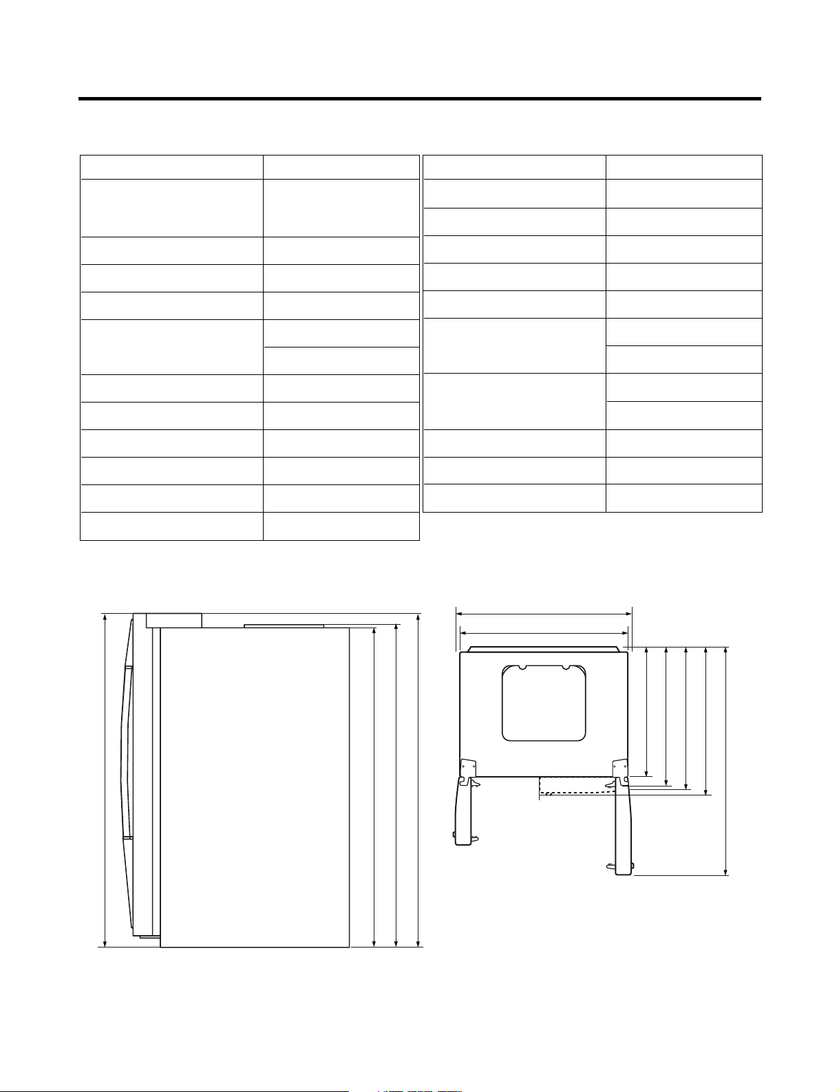
SPECIFICATIONS
Ref No. : LRSC26944**
ITEMS SPECIFICATIONS
DIMENSIONS 908 X 896 X 1771 mm
11
5
W
X
D X H (35
/16
X
35
/16
11
/16
X
69
in.)
NET WEIGHT 149 kg (328.5 lbs.)
COOLING SYSTEM Fan Cooling
TEMPERATURE CONTROL Micom Control
DEFROSTING SYSTEM Full Automatic
Heater Defrost
INSULATION Cyclo-Pentane
COMPRESSOR PTC Starting Type
EVAPORATOR Fin Tube Type
CONDENSER Wire Condenser
REFRIGERANT R134a (185g) (6
1
/2 oz.)
LUBRICATING OIL FREOL @10G (320 cc)
ITEMS SPECIFICATIONS
DRIER MOLECULAR SIEVE XH-7
CAPILLARY TUBE ID Ø0.83
FIRST DEFROST 4 - 5 Hours
DEFROST CYCLE 13 - 15 Hours
DEFROSTING DEVICE Heater, Sheath
ANTI-SWEAT HEATER Dispenser Duct Door Heater
Dispenser Heater
ANTI-FREEZING HEATER Water Tank Heater
Damper Heater
FREEZER LAMP 40W (2 EA)
REFRIGERATOR LAMP 40W (4 EA)
DISPENSER LAMP 15W (1 EA)
in.)
16
/
11
1771 mm (69
1004 mm (391/2 in.)
3
908 mm (35
in.)
in.)
2
/
1
1741.5 mm (68
Front View Top View
in.)
4
/
16
3
/
11
1771 mm (69
1746.5 mm (68
/4 in.)
in.)
in.)
in.)
2
8
8
/
/
1
/
5
5
724 mm (28
779 mm (30
829 mm (32
in.)
in.)
8
/
16
5
/
5
897 mm (35
1261 mm (49
- 4 -
SPECIFICATIONS
724 mm (28
1
/
2
in.)
1004 mm (391/2 in.)
908 mm (35
3
/4 in.)
779 mm (30
5
/
8
in.)
829 mm (32
5
/
8
in.)
897 mm (35
5
/
16
in.)
1261 mm (49
5
/
8
in.)
1741.5 mm (68
1
/
2
in.)
1746.5 mm (68
3
/
4
in.)
1771 mm (69
11
/
16
in.)
1771 mm (69
11
/
16
in.)
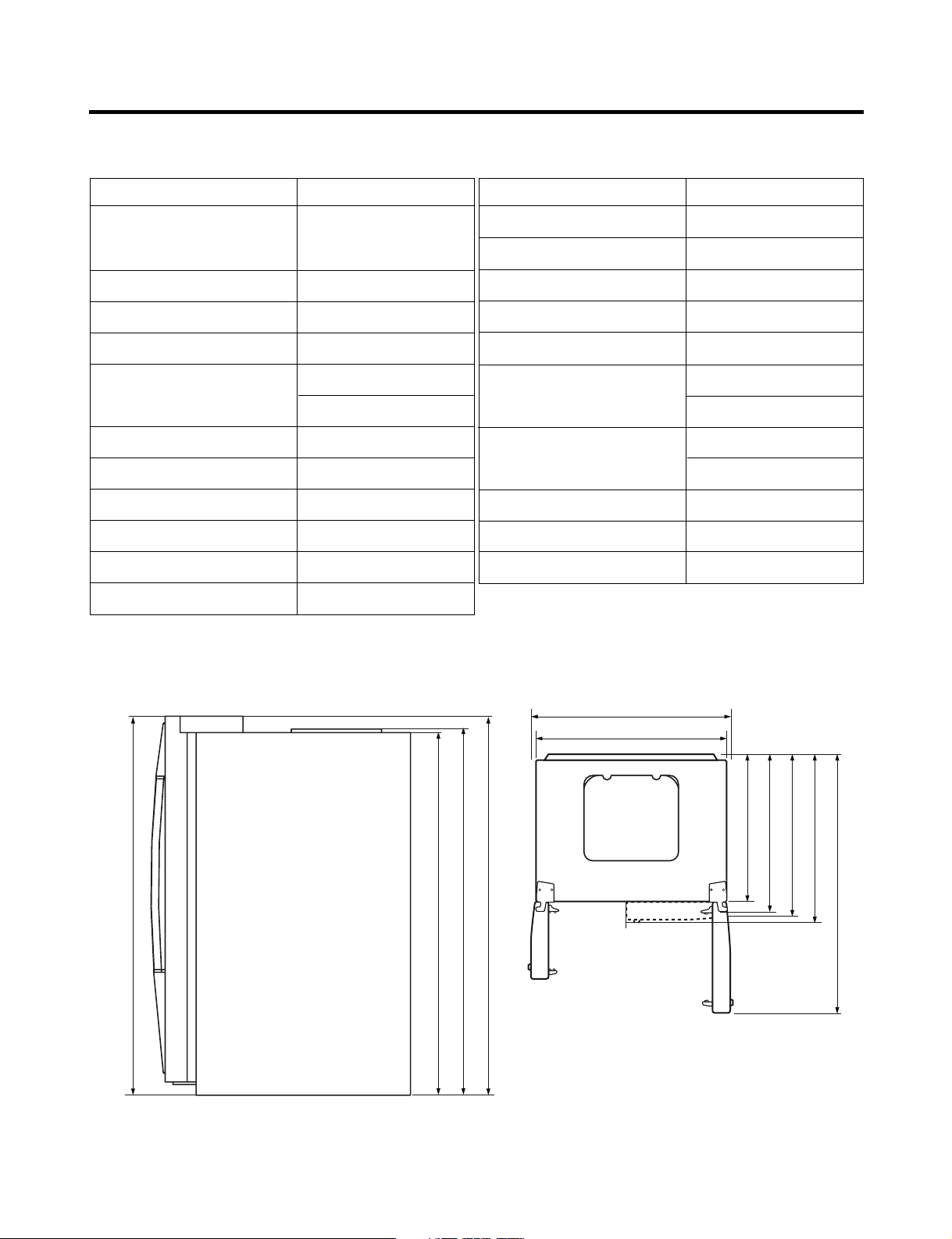
Ref No. : LRSC26930**
ITEMS SPECIFICATIONS
DIMENSIONS 908 X 896 X 1771 mm
W
X D X
H (35
NET WEIGHT 149 kg (328.5 lbs.)
COOLING SYSTEM Fan Cooling
TEMPERATURE CONTROL Micom Control
DEFROSTING SYSTEM Full Automatic
INSULATION Cyclo-Pentane
COMPRESSOR PTC Starting Type
EVAPORATOR Fin Tube Type
CONDENSER Wire Condenser
REFRIGERANT R134a (185g) (6
LUBRICATING OIL FREOL @10G (320 cc)
11
/16X355/16X6911/16 in.)
Heater Defrost
1
/2 oz.)
ITEMS SPECIFICATIONS
DRIER MOLECULAR SIEVE XH-7
CAPILLARY TUBE ID Ø0.83
FIRST DEFROST 4 - 5 Hours
DEFROST CYCLE 13 - 15 Hours
DEFROSTING DEVICE Heater, Sheath
ANTI-SWEAT HEATER Dispenser Duct Door Heater
Dispenser Heater
ANTI-FREEZING HEATER Water Tank Heater
Damper Heater
FREEZER LAMP 40W (1 EA)
REFRIGERATOR LAMP 40W (4 EA)
DISPENSER LAMP 15W (1 EA)
Front View Top View
- 5 -

SPECIFICATIONS
Ref No. : LRSC26920**, LRSC26922**
ITEMS SPECIFICATIONS
DIMENSIONS 908 X 896 X 1771 mm
W
X D X
H (35
NET WEIGHT 149 kg (328.5 lbs.)
COOLING SYSTEM Fan Cooling
TEMPERATURE CONTROL Micom Control
DEFROSTING SYSTEM Full Automatic
INSULATION Cyclo-Pentane
COMPRESSOR PTC Starting Type
EVAPORATOR Fin Tube Type
CONDENSER Wire Condenser
REFRIGERANT R134a (185g) (6
LUBRICATING OIL FREOL @10G (320 cc)
11
/16X355/16X6911/16 in.)
Heater Defrost
1
/2 oz.)
ITEMS SPECIFICATIONS
DRIER MOLECULAR SIEVE XH-7
CAPILLARY TUBE ID Ø0.83
FIRST DEFROST 4 - 5 Hours
DEFROST CYCLE 13 - 15 Hours
DEFROSTING DEVICE Heater, Sheath
ANTI-SWEAT HEATER Dispenser Duct Door Heater
Dispenser Heater
ANTI-FREEZING HEATER Water Tank Heater
Damper Heater
FREEZER LAMP 40W (1 EA)
REFRIGERATOR LAMP 40W (4 EA)
DISPENSER LAMP 15W (1 EA)
in.)
16
/
11
1771 mm (69
1004 mm (391/2 in.)
3
908 mm (35
in.)
in.)
2
/
1
1741.5 mm (68
Front View Top View
in.)
4
/
16
3
/
11
1771 mm (69
1746.5 mm (68
/4 in.)
in.)
in.)
in.)
2
8
8
/
/
1
/
5
5
724 mm (28
779 mm (30
829 mm (32
in.)
in.)
8
/
16
5
/
5
897 mm (35
1261 mm (49
- 6 -

SPECIFICATIONS
Ref No. : LRSC26910**, LRSC26911**
ITEMS SPECIFICATIONS
DIMENSIONS 908 X 896 X 1771 mm
11
5
W
X
D X H (35
/16
X
35
/16
11
/16
X
69
in.)
NET WEIGHT 149 kg (328.5 lbs.)
COOLING SYSTEM Fan Cooling
TEMPERATURE CONTROL Micom Control
DEFROSTING SYSTEM Full Automatic
Heater Defrost
INSULATION Cyclo-Pentane
COMPRESSOR PTC Starting Type
EVAPORATOR Fin Tube Type
CONDENSER Wire Condenser
REFRIGERANT R134a (185g) (6
1
/2 oz.)
LUBRICATING OIL FREOL @10G (320 cc)
ITEMS SPECIFICATIONS
DRIER MOLECULAR SIEVE XH-7
CAPILLARY TUBE ID Ø0.83
FIRST DEFROST 4 - 5 Hours
DEFROST CYCLE 13 - 15 Hours
DEFROSTING DEVICE Heater, Sheath
ANTI-SWEAT HEATER Dispenser Duct Door Heater
Dispenser Heater
ANTI-FREEZING HEATER Water Tank Heater
Damper Heater
FREEZER LAMP 40W (1 EA)
REFRIGERATOR LAMP 40W (3 EA)
DISPENSER LAMP 15W (1 EA)
in.)
16
/
11
1771 mm (69
1004 mm (391/2 in.)
3
908 mm (35
in.)
in.)
2
/
1
1741.5 mm (68
Front View Top View
in.)
4
/
16
3
/
11
1771 mm (69
1746.5 mm (68
/4 in.)
in.)
in.)
in.)
2
8
8
/
/
1
/
5
5
724 mm (28
779 mm (30
829 mm (32
in.)
in.)
8
8
/
/
5
1
892 mm (35
1261 mm (49
- 7 -
SPECIFICATIONS
Ref No. : LRSC26980TT
ITEMS SPECIFICATIONS
DIMENSIONS 908 X 896 X 1771 mm
11
5
W
X
D X H (35
/16
X
35
/16
11
/16
X
69
in.)
NET WEIGHT 154 kg (339.5 lbs.)
COOLING SYSTEM Fan Cooling
TEMPERATURE CONTROL Micom Control
DEFROSTING SYSTEM Full Automatic
Heater Defrost
INSULATION Cyclo-Pentane
COMPRESSOR PTC Starting Type
EVAPORATOR Fin Tube Type
CONDENSER Wire Condenser
REFRIGERANT R134a (185g) (6
1
/2 oz.)
LUBRICATING OIL FREOL @10G (320 cc)
ITEMS SPECIFICATIONS
DRIER MOLECULAR SIEVE XH-7
CAPILLARY TUBE ID Ø0.83
FIRST DEFROST 4 - 5 Hours
DEFROST CYCLE 13 - 15 Hours
DEFROSTING DEVICE Heater, Sheath
ANTI-SWEAT HEATER Dispenser Duct Door Heater
Dispenser Heater
ANTI-FREEZING HEATER Water Tank Heater
Damper Heater
FREEZER LAMP 40W (2 EA)
REFRIGERATOR LAMP 40W (4 EA)
DISPENSER LAMP 15W (1 EA)
in.)
16
/
11
1771 mm (69
1004 mm (391/2 in.)
3
908 mm (35
in.)
in.)
2
/
1
1741.5 mm (68
Front View Top View
in.)
4
/
16
3
/
11
1771 mm (69
1746.5 mm (68
/4 in.)
in.)
in.)
in.)
2
8
8
/
/
1
/
5
5
724 mm (28
779 mm (30
829 mm (32
in.)
in.)
8
/
16
5
/
5
897 mm (35
1261 mm (49
- 8 -

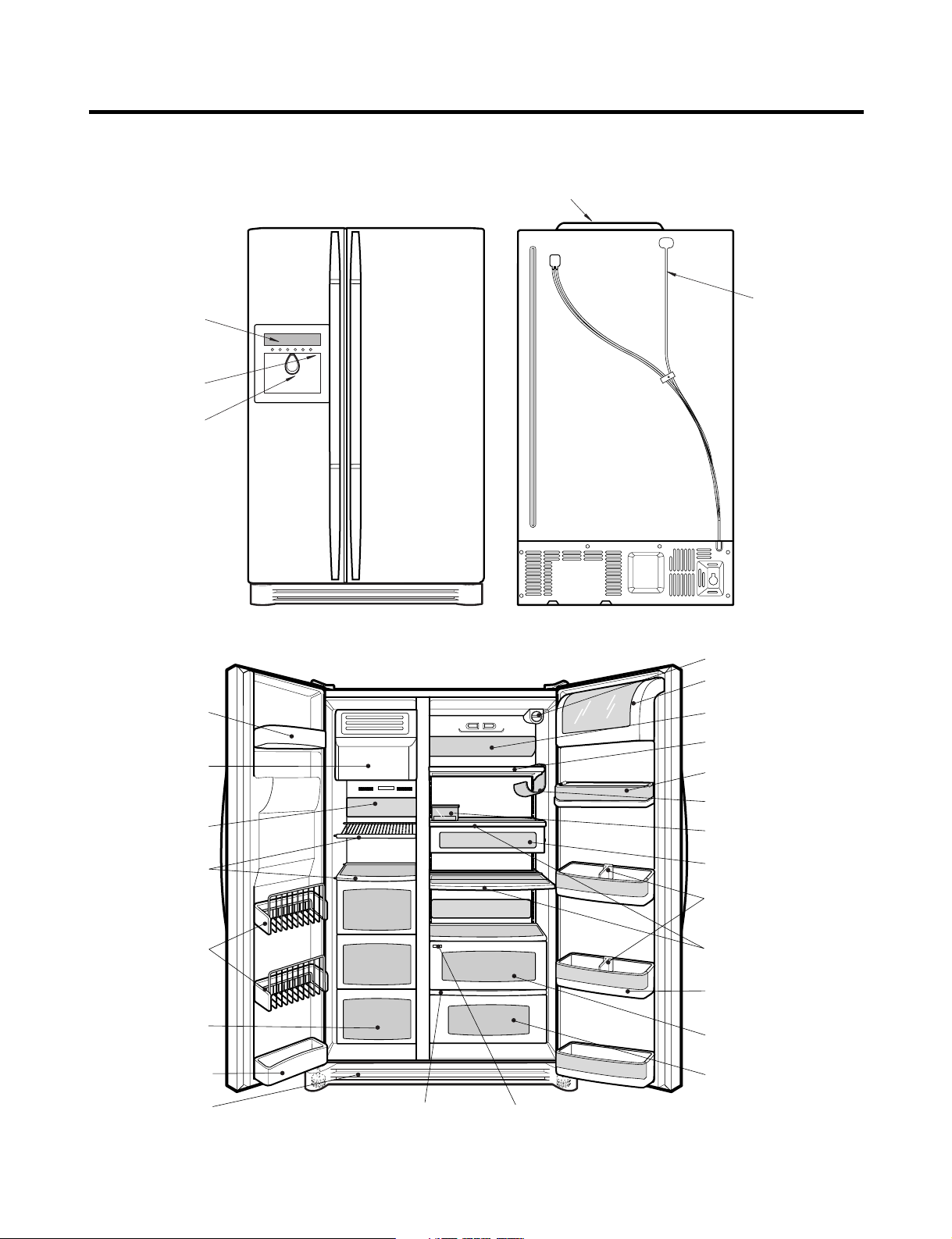
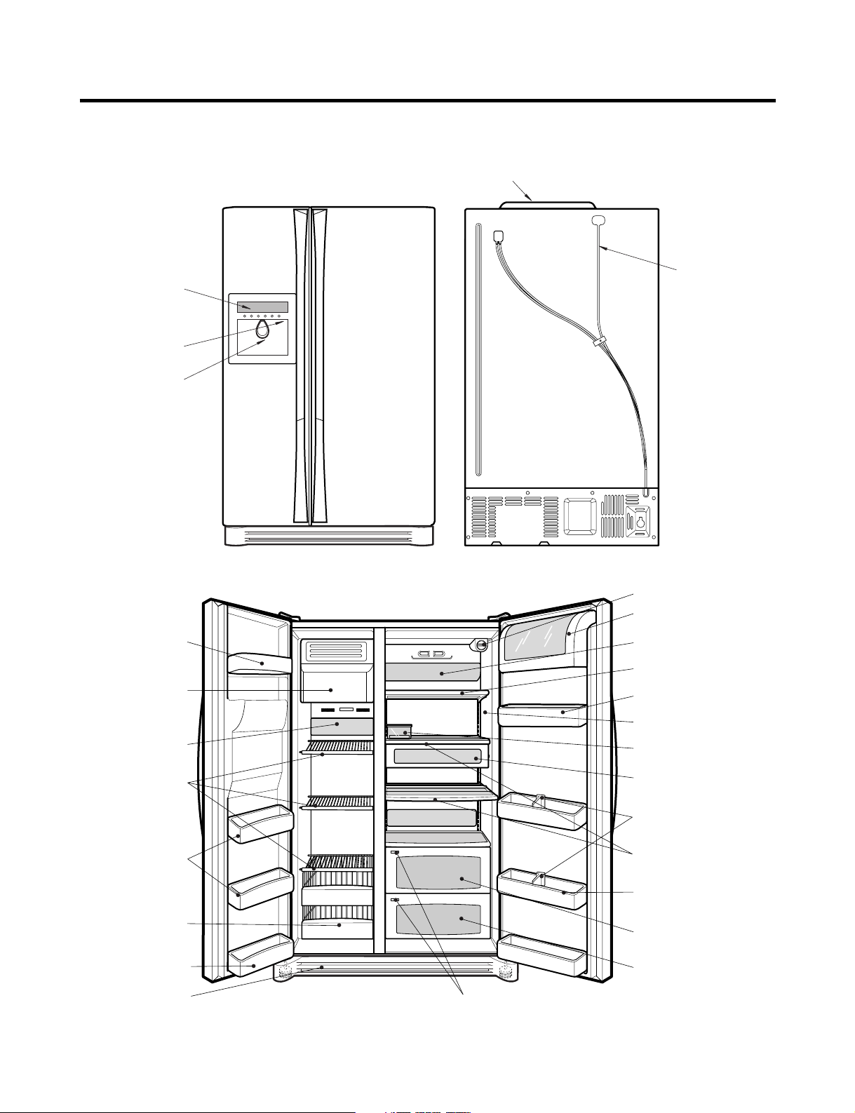
PARTS IDENTIFICATION
Humidity SwitchOptiChill Display
Lamp
Shelf
Egg Box
Snack Drawer
Vegetable Drawer
OptiChill
Door Rack
Shelf
Grab and Go
Can Server
Lamp
Lower Cover
Dairy Products Corner
Water Filter
Door Rack
Drawer
(Wire/Plastic)
Freezer
Compartment
Refrigerator
Compartment
Automatic
Icemaker
Door Rack
Shelf
Door Rack
Bottle Guide
Display Panel
Dispenser Lamp
Ice & Water
Dispenser Button
PCB Cover
Water Tubes
Ref No. : LRSC26944**
- 9 -
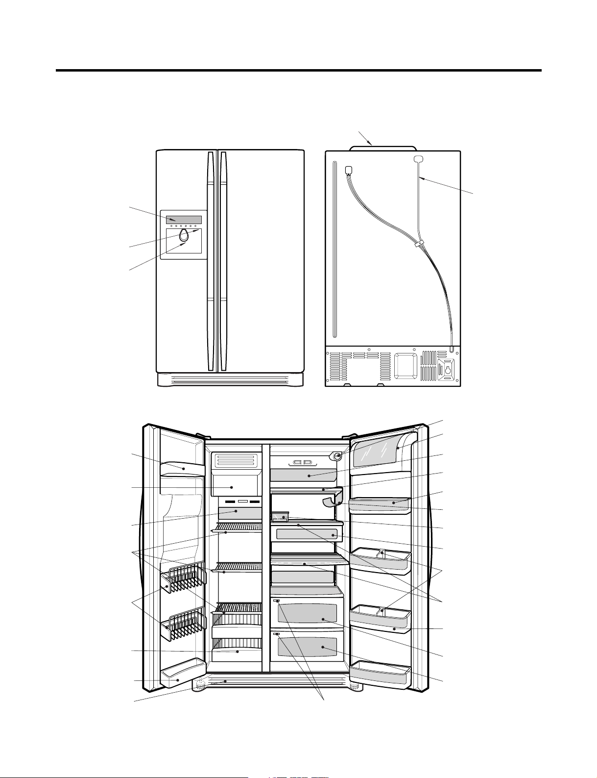
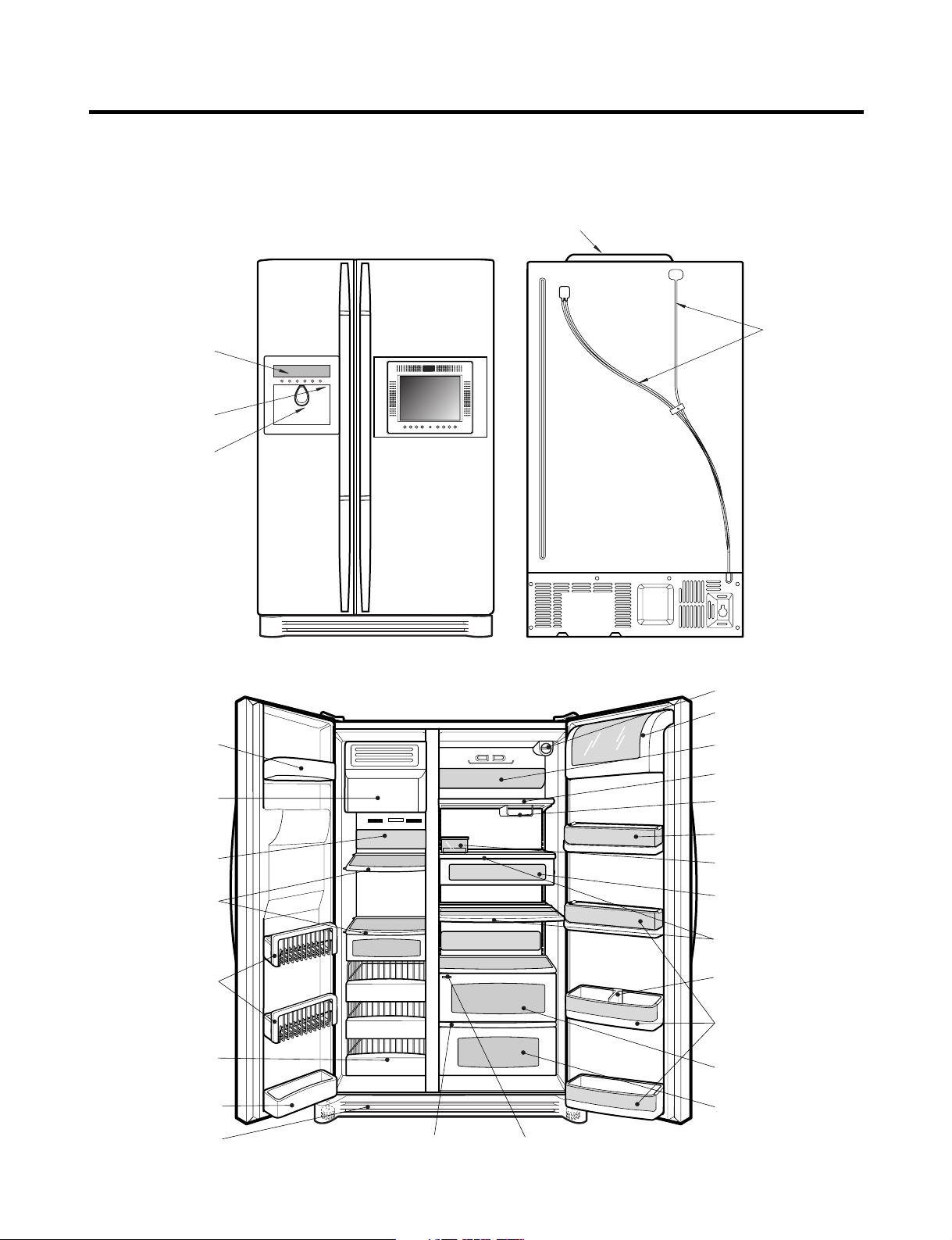
PARTS IDENTIFICATION
Humidity Switch
Lamp
Shelf
Egg Box
Snack Drawer
Vegetable Drawer
OptiChill
Door Rack
Shelf
Grab and Go
Wine Holder
Lamp
Lower Cover
Dairy Products Corner
Door Rack
Drawer
(Wire/Plastic)
Freezer
Compartment
Refrigerator
Compartment
Automatic
Icemaker
Door Rack
Shelf
Bottle Guide
Display Panel
Dispenser Lamp
Ice & Water
Dispenser Button
OptiChill Display
Door Rack
Water Filter
PCB Cover
Water Tubes
Ref No. : LRSC26930**
- 10 -
PARTS IDENTIFICATION
Humidity Switch
Lamp
Shelf
Egg Box
Snack Drawer
Vegetable Drawer
Vegetable Drawer
/Meat Drawer
Door Rack
Shelf
Door Rack
Wine Holder
Lamp
Lower Cover
Dairy Products Corner
Door Rack
Drawer
(Wire/Plastic)
Freezer
Compartment
Refrigerator
Compartment
Automatic
Icemaker
Door Rack
Shelf
Bottle Guide
Display Panel
Dispenser Lamp
Ice & Water
Dispenser Button
PCB Cover
Water Tubes
Door Rack
Water Filter
Ref No. : LRSC26920**, LRSC26922**
- 11 -
PARTS IDENTIFICATION
Lamp
Shelf
Egg Box
Snack Drawer
Vegetable Drawer
Vegetable Drawer
/Meat Drawer
Door Rack
Shelf
Door Rack
Wine Holder
Lamp
Lower Cover
Dairy Products Corner
Door Rack
Drawer
(Wire/Plastic)
Freezer
Compartment
Refrigerator
Compartment
Automatic
Icemaker
Door Rack
Shelf
PCB Cover
Water Tubes
Door Rack
Water Filter
Humidity Switch
Bottle Guide
Display Panel
Dispenser Lamp
Ice & Water
Dispenser Button
Ref No. : LRSC26910**, LRSC26911**
- 12 -
PARTS IDENTIFICATION
Humidity SwitchOptiChill Display
Lamp
Shelf
Egg Box
Snack Drawer
Vegetable Drawer
OptiChill
Door Rack
Shelf
Grab and Go
Can Server
Lamp
Lower Cover
Dairy Products Corner
Water Filter
Door Rack
Drawer
(Wire/Plastic)
Freezer
Compartment
Refrigerator
Compartment
Automatic
Icemaker
Door Rack
Shelf
Door Rack
Bottle Guide
Display Panel
Dispenser Lamp
Ice & Water
Dispenser Button
PCB Cover
Water Tubes
Ref No. : LRSC26980TT
- 13 -
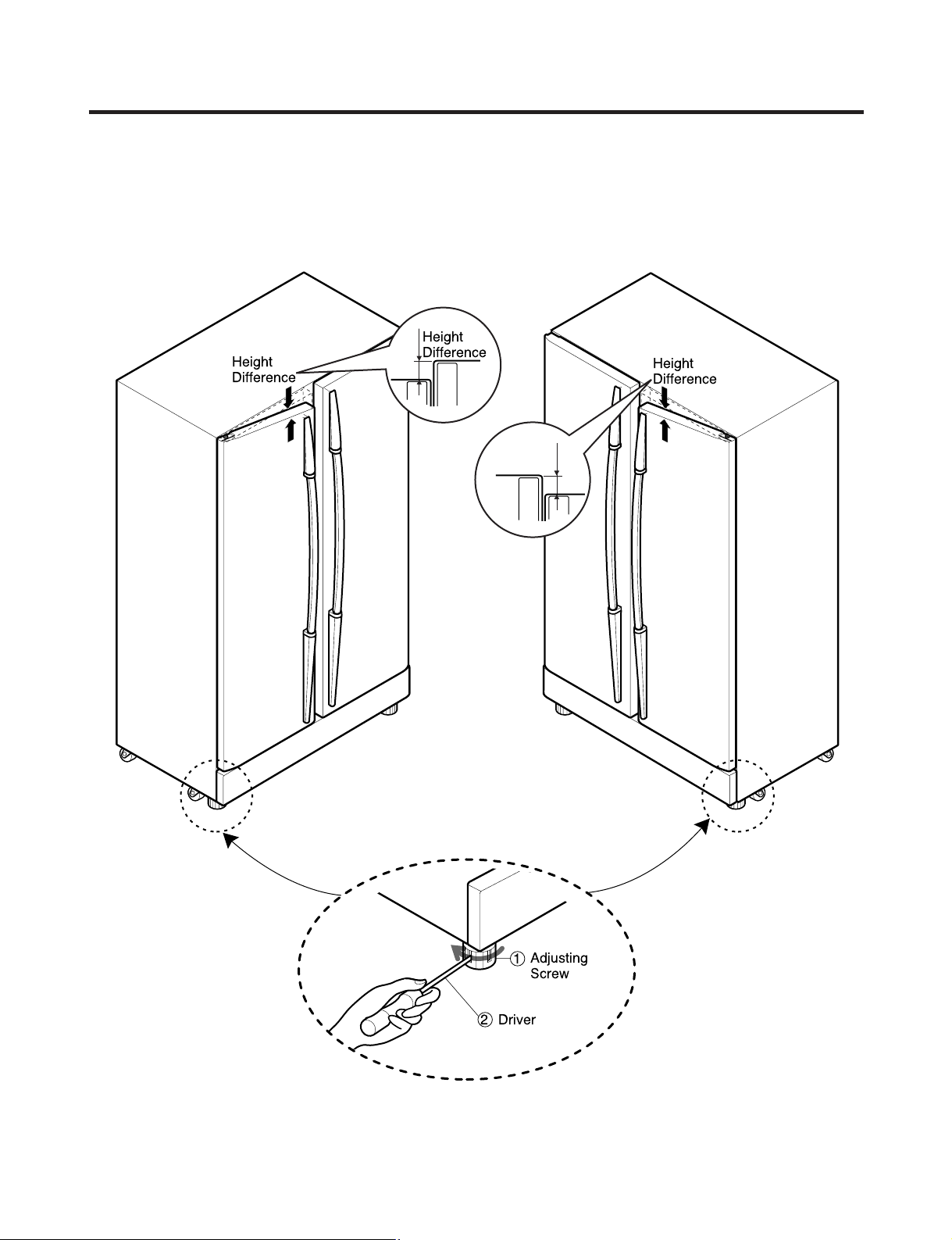
HOW TO INSTALL REFRIGERATOR
Adjusting
Screw
Driver
Height
Difference
Height
Difference
Height
Difference
Height
Difference
1
2
How to Adjust Door Height of Refrigerator
■ Level the refrigerator first. (If the refrigerator is not installed on a flat floor, the height of freezer and refrigerator doors
may not be the same.)
If the freezer door is lower than the refrigerator door: If the freezer door is higher than the refrigerator door:
Insert a driver into the groove of the adjusting
screw and turn in the direction of the arrow (clockwise)
until the refrigerator is level.
- 14 -
Insert a driver into the groove of the adjusting
screw and turn in the direction of the arrow (clockwise)
until the refrigerator is level.
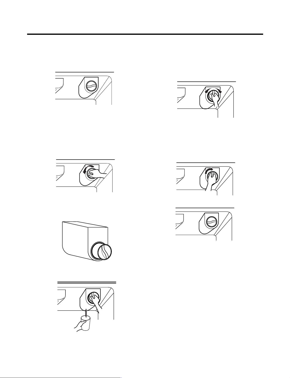
HOW TO INSTALL REFRIGERATOR
Filter
Replace the filter when the indicator light comes on or the
performance of the icemaker or water dispenser decreases
noticeably.
After changing the water filter cartridge, reset the water
filter status display and indicator light by pressing and
holding the BUTTON for 3 seconds.(page 18)
1. Remove the old cartridge.
Twist the knob of the cartridge counter clockwise.
2. Replace with a new cartridge.
Take the new cartridge out of its packaging and remove the
protective cover from the o-rings.
With the cartridge knob in the vertical position, push the
new filter cartridge into the cover until it stops.
If you can’t turn the filter from side to side, it isn’t fully
inserted. Push it in firmly and twist it into place. You will
hear the snap when it clicks into place.
Using the handle, twist the cartridge clockwise about 1/4
turn.
When the cartridge is removed, you will feel it click .
Pull out the cartridge.
NOTE: There will be some water(25cc) in the filter
cartridge. Some spilling may occur. Catch it in a
bowl or towel.
3. After replacing filter, dispense water through the water
dispenser for 3 minutes to purge the system.
There may be a little air in the line, causing noise or
hissing. Run the water at the dispenser until the hissing
stops.
NOTE: - To purchase replacement water filter cartridges,
visit your local appliance dealer or part distributor,
or call 1-877-714-7486.
- You can also visit our website :
www.lgappliances.com
- 15 -
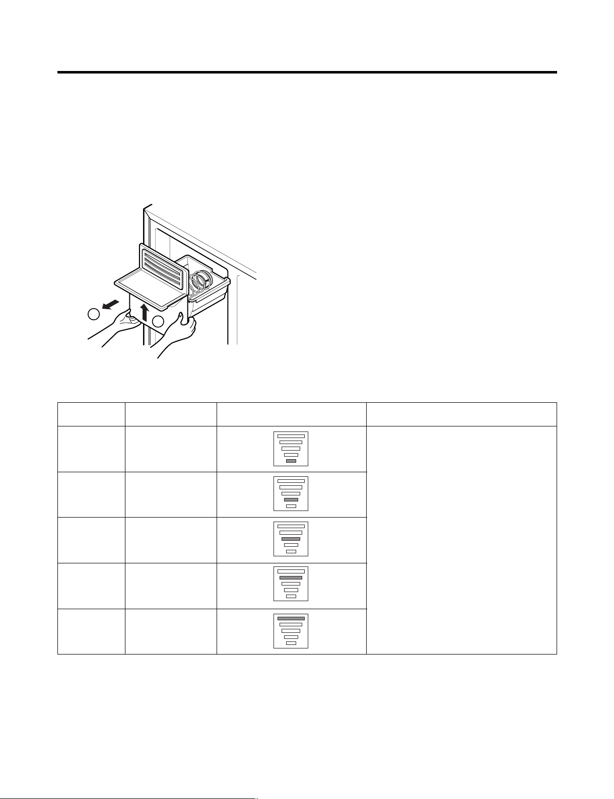
HOW TO INSTALL REFRIGERATOR
2
1
Ice Maker
1) How to Control the Amount of Water Supplied to Icemaker.
Caution : • Do not put hands or tools into the chute to confirm the operation of geared motor.
It may damage the refrigerator or hurt your hands.
To gain access to the ice maker, remove the ice bin in the upper part of the freezer compartment. Then use the water
control switch to change the amount of water supplied to the ice maker.
Water supply amount TABLE
STAGE TIME TO SUPPLY INDICATIONS REMARKS
1
2
3
4
5
4 sec.
4.5 sec.
5 sec.
5.5 sec.
6 sec.
The water amount will vary depending
on the Water Control Switch setting as
well as the water pressure of the
connected water line.
- 16 -
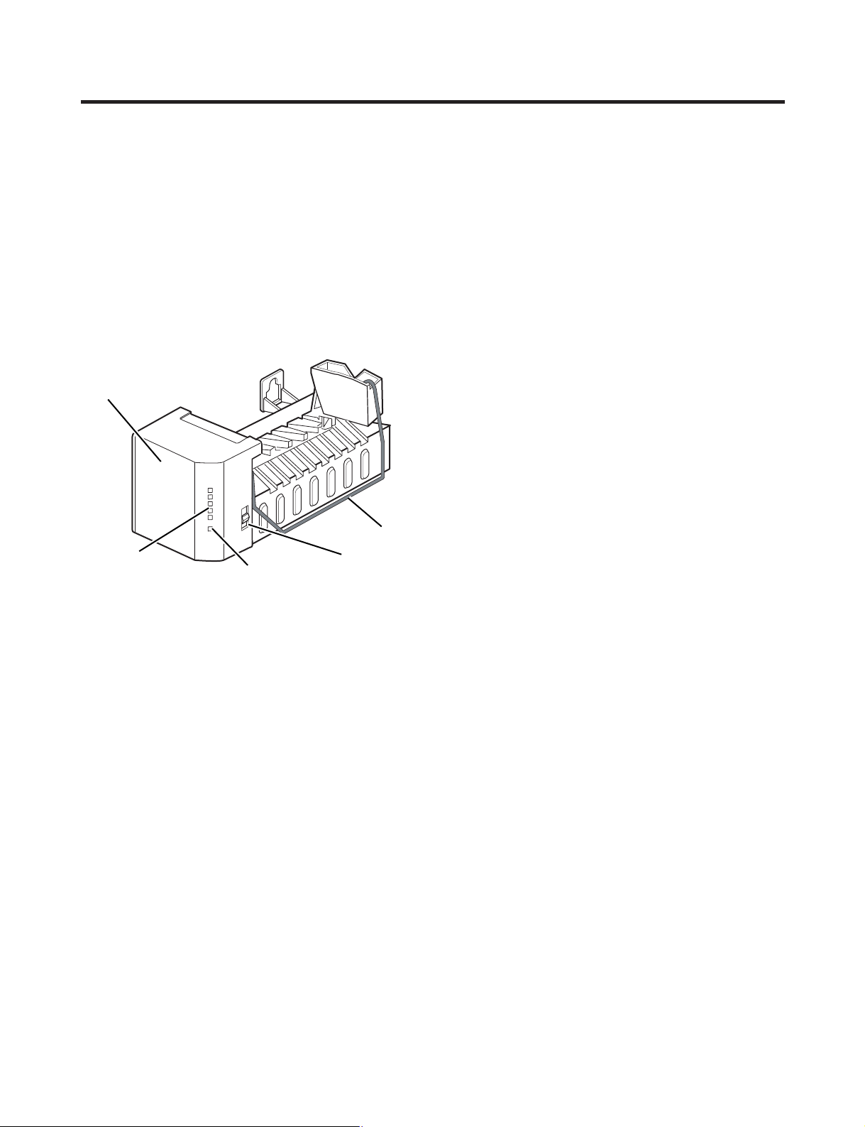
HOW TO INSTALL REFRIGERATOR
ww
WARNING
Personal Injury Hazard
Avoid contact with the moving parts of the ejector
mechanism or with the heating element that releases
the cubes. DO NOT place fingers or hands on the
automatic icemaking mechanism while the refrigerator
is plugged in.
2) Operating instructions
A newly-installed refrigerator may take up to 24 hours
to begin making ice.
Icemaker
Feeler Arm
Cube Size
Indicator Light
The icemaker will produce eight cubes per
cycle—approximately 120–150 cubes in a 24-hour period,
depending on freezer compartment temperature, room
temperature, number of door openings and other operating
conditions.
If the refrigerator is used before the water connection is
made to the icemaker, set the power switch to O (off).
When the refrigerator has been connected to the water
supply, set the power switch to I (on).
The icemaker will fill with water when it cools to freezing. A
newly-installed refrigerator may take up to 24 hours to
begin making ice cubes.
Throw away the first few batches of ice to allow the water
line to clear.
Be sure nothing interferes with the sweep of the feeler arm.
When the bin fills to the level of the feeler arm, the
icemaker will stop producing ice.
It is normal for several cubes to be stuck together.
If ice is not used frequently, old ice cubes will become
cloudy, taste stale, and shrink.
Water Supply
Control Switch
Power Switch
NOTE: If the cube size is smaller or larger than you
expected, you can regulate the size with the cube size
button. (normally caused by variations in water pressure.)
Every time you press the cube size button, the indicator
light goes up. The higher the position indicated, the larger
the cubes will be. (1st step is the next after the 5th step.)
3) When you should set the icemaker power
switch to O (off)
• When the water supply will be shut off for several hours.
• When the ice storage bin is removed for more than a
minute or two.
• When the refrigerator will not be used for several days.
4) Normal sounds you may hear
• The icemaker water valve will buzz as the icemaker fills
with water. If the power switch is in the I (on) position, it
will buzz even if it has not yet been hooked up to water.
To stop the buzzing, move the power switch to O (off).
NOTE: Keeping the power switch in the I (on) position
before the water line is connected can damage the
icemaker.
• You will hear the sound of cubes dropping into the bin
and water running in the pipes as the icemaker refills.
5) Preparing for Vacation
Set the icemaker power switch to O (off) and shut off the
water supply to the refrigerator.
If the ambient temperature will drop below freezing, have a
qualified servicer drain the water supply system (on some
models) to prevent serious property damage due to
flooding from ruptured water lines or connections.
- 17 -
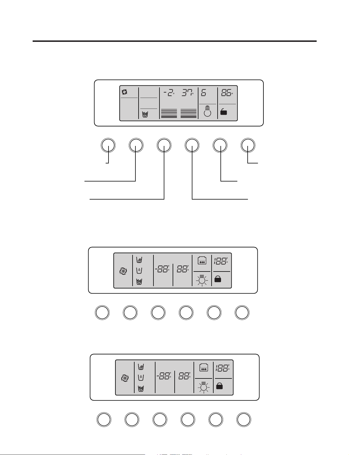
MICOM FUNCTION
ICEBEAM
COOLING
OFF
CUBE
FILTER
MONTH
EXPRESS/JET FRZ DISPENSER FREEZER REFRIGERATOR FILTER/LIGHT LOOK
ROOM TEMP
DISPENSER & KEY
F
WATER
5
4
3
2
1
CRUSH
F F
3 SECS
Dispenser selection
button
Express Freezer/Jet Freezer
function selection button
Dispenser and Button
Lock button
Filter Timer Reset & Dispenser
Light Toggle
Refrigerator Compartment
Temperature Setting
Freezer Compartment
Temperature Setting
EXPRESS
DIGITAL CONTROL
FRZ TEMP REF TEMP
JET
CUBE
FILTER RESET
HOLD 3SECS
EXPRESS/JET FRZ DISPENSER FREEZER
REFRIGERATOR
FILTER RESET/LIGHT
LOOK
ROOM TEMP
LOCK
DISPENSER & KEY
WATER
CRUSH
3 SECS
F
C
F
C
F
C
FILTER
ON
DIGITAL CONTROL
FRZ TEMP REF TEMP
OFF
CUBE
FILTER RESET
HOLD 3SECS
EXPRESS FRZ DISPENSER FREEZER
REFRIGERATOR
FILTER RESET/LIGHT
LOOK
ROOM TEMP
LOCK
DISPENSER & KEY
WATER
CRUSH
3 SECS
F
C
F
C
F
C
FILTER
1. Monitor Panel
1-1. LRSC26944**, LRSC26980TT
1-2. LRSC26930**
1-3. LRSC26910**, LRSC26911**, LRSC26920**, LRSC26922**
- 18 -
MICOM FUNCTION
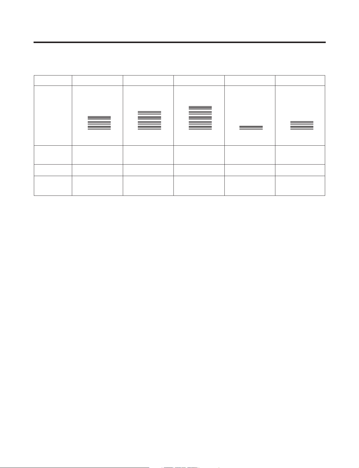
2. Refrigerator Functions
2-1-1. Temperature Selection (LRSC26944**, LRSC26980TT)
Division Power Initially On 1st Press 2st Press 3th Press 4th Press
Setting
temperature
Temperature
Control
Freezer Control
Refrigeration
Control
* The temperature can vary ±3 °C depending on the load condition.
5
4
3
2
1
Medium Medium Cold Coldest Warmest Medium Warm
-2 °F -5 °F -8 °F 7 °F 4 °F
37 °F 34 °F 32 °F 46 °F 41 °F
5
4
3
2
1
5
4
3
2
1
5
4
3
2
1
5
4
3
2
1
❉ Whenever pressing the button, setting is repeated in the order of (Medium) ➝ (Medium Cold) ➝ (Coldest) ➝ (Warmest) ➝
(Medium Warm).
• The actual inner temperature varies depending on the food status, as the indicated setting temperature is a target
temperature, not the actual temperature within the refrigerator.
• A newly installed refrigerator will take 24 hours minimum for temperatures to stabilize. The temperature should be
checked and adjusted as necessary after 2 or 3 days.
2-1-2. LCD Back Light Control (LRSC26944**, LRSC26980TT)
1. In order to see the LCD display more easily, the backlight is turned on for one minute at the initial application of power, for
20 seconds when buttons are pressed, when a door is opened, and for 20 seconds after the door is closed.
2. When any display button is pressed while the backlight is off, the bell sounds and the backlight is turned on, but the
button function is not performed. In other words, pressing any button turns on the backlight but does not cause any
function to be initiated.
3. To check the LCD graphic and back light ON/OFF status, press and hold the EXPRESS/JET FRZ and FREEZER buttons.
This will turn the back light on and illuminate all of the graphics. When the buttons are released, the graphic display
returns to its previous setting and the back light is turned off.
2-1-3. Room temperature display function
1. The sensor for the ROOM TEMP display is located under the upper right hinge cover. Factors such as air flow, lighting,
and other appliances operating within the room, may cause the display to differ from other temperature displays in the
same room.
2. Ambient temperature is displayed between 16°F and 120°F. Temperatures 15°F and below are displayed as Lo and
temperatures 121°F and above are displayed as Hi. If the ambient temperature sensor fails, Er will be displayed.
- 19 -
MICOM FUNCTION
DISPENSER & KEY
3 SECS
LOCK
DISPENSER & KEY
3 SECS
LOCK CONTROL
DISPENSER & KEY
3 SECS
LOCK
DISPENSER & KEY
3 SECS
LOCK CONTROL
Ex) Select
LOCK
Ex) Select
LOCK again
Ex) Select
LOCK
Ex) Select
LOCK again
In initial
Power On
Classification
Filter Status
Display
Pass of
a month
Pass of
2 months
Pass of
3 months
Pass of
4 months
Pass of
5 months
Pass of
6 months
3 SECS
FILTER
MONTH
FILTER
MONTH
FILTER
MONTH
FILTER
MONTH
FILTER
MONTH
FILTER
MONTH
FILTER
MONTH
FILTER LIGHT
In initial Power On
/ Filter RESET
Replace indicator
light on
Classification
Filter Status
Display
FILTER
FILTER RESET
HOLD 3SECS
FILTER
3 SECS
FILTER LIGHT
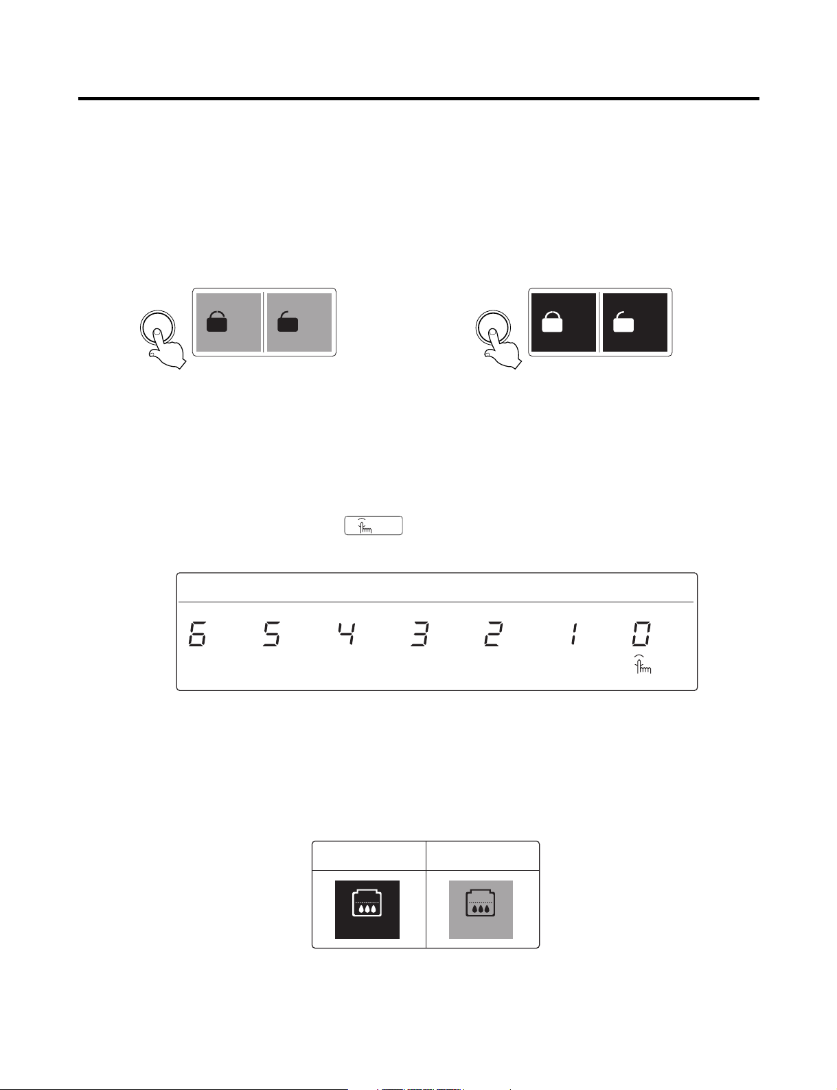
2-1-4. Lock function (dispenser and display button lock)
1. When the refrigerator is first powered up, the Lock function is turned off.
2. To lock the display, the dispenser, and the control panel, press and hold the LOCK button for more than 3 seconds. The
LOCK text on the display will be turned on.
3. To unlock the controls, press and hold the lock button for more than 3 seconds. The LOCK text on the display will be
turned off.
LCD (LRSC26944**, LRSC26980TT) LED (All models except LRSC26944**, LRSC26980TT)
2-1-5. Filter condition display function
LCD (LRSC26944**, LRSC26980TT)
1. This units displays the months left before the water filter needs to be changed. It starts when the unit is first plugged in.
2. After 6 months have passed the filter change will appear on the display. It will show FILTER LIGHT 3 SECS.
3. Press and hold the filter button for 3 seconds to reset the filter timer.
LED (All models except LRSC26944**, LRSC26980TT)
1. There is a replacement indicator light for the water filter cartridge on the dispenser.
2. The water filter should be replaced every six months or about 28,000 seconds' filtering time.
3. The water filter light and FILTER RESET HOLD 3 SECS will show in the display to remind you to change the filter soon.
4. After replacing the filter, press and hold the lock button for more than 3 seconds. The FILTER RESET HOLD 3 SECS will
turn off.
- 20 -
MICOM FUNCTION
DISPENSER
LCD LED
CUBE
WATER
CRUSH
CUBE
WATER
CRUSH
Pressing
Switch
LCD (LRSC26944**, LRSC26980TT)
LED (LRSC26930**)
LED (LRSC26910**, LRSC26911**, LRSC26920**, LRSC26922**)
EXPRESS/JET FRZ
OFF
EXPRESS FRZ
JET FRZ
EXPRESS/JET FRZ
EXPRESS
JET
EXPRESS FRZ
ON
OFF
Dispenser Iight OFF
LCD
Dispenser Iight ON
LCD
Dispenser Iight ON/OFF
LED
CN
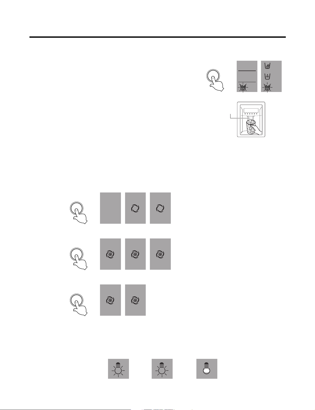
2-2. Dispenser use selection
You can select water or ice.
❉ Select water, crushed ice, or ice cubes by cycling through the selections when
pressing the DISPENSER button.
❉ Hold your cup in the dispenser for a few seconds after dispensing ice or water to
allow the last pieces of ice or drops of water to fall into the cup.
2-3. Express freezing/JET freezing selection
Please select this function for prompt freezing.
• The functions are cycled in the order shown below when the EXPRESS/JET FRZ button is pressed.
• The arrow mark graphic remains at the On status after flickering 4 times when selecting Special Refrigeration EXPRESS
FRZ or JET FRZ.
• EXPRESS FREEZE and JET FREEZE operate for a set time and then default to normal freezer operation.
2-4. Dispenser Light
• Dispenser switch or dispenser light button turns the dispenser light in the dispenser on and off.
• The dispenser light turns off automatically after 7 minutes.
- 21 -

MICOM FUNCTION
2-5. Express freezing
1. EXPRESS FREEZING improves the cooling speed of the freezer by running the compressor and the freezer fan.
2. In the event of power failure, EXPRESS FREEZING is cancelled and the freezer defaults to normal operation.
3. The temperature setting is not changed when EXPRESS FREEZING is selected.
4. The freezer compartment and refrigerator temperature settings can be changed even when EXPRESS FREEZING is
selected and the cycle is underway.
5. The refrigerator compartment will operate at its usual setting even when EXPRESS FREEZING is selected or in progress.
6. If you select EXPRESS FREEZING, the refrigerator will default to its original setting at the end of the cycle.
7. If the defrost cycle is scheduled to come on while EXPRESS FREEZING is selected, EXPRESS FREEZING will operate
only for the time that is not used by the defrost setting.
8. If you press EXPRESS FREEZING during the defrost cycle, the EXPRESS FREEZING indicator will turn on but the cycle
will not run until the defrost cycle is completed.
9. If you press EXPRESS FREEZING within 7 minutes of the compressor’s last run cycle, the EXPRESS FREEZING cycle
will not begin until the 7 minute delay is complete.
10. The freezer fan runs at high speed when Express Freezing is selected.
2-6. Jet Freezing
1. Jet Freezing improves the cooling speed of the Jet Freezing Compartment by running the compressor and the Jet
Freezing Compartment fan.
2. If there is a power failure, the Jet Freezing cycle is released and the freezer defaults to its original setting.
3. If Jet Freezing is selected, the compressor (after the compressor delay time has passed) and the freezer fan will be
turned on. The temperature in the freezer will drop and the fan motor will be turned off for a set time, but the Jet Freezing
fan will run for no more than two hours. After that, the Jet Freezing function is terminated and the freezer defaults to its
original setting.
4. To keep the fan motor from freezing, it is switched on for 10 seconds once an hour.
5. The fan motor of jet freezing box will not be detected as a failure. (dc 12v operation)
6. When checking the Jet Freezing function, the Jet Freezing Compartment fan motor is switched on for 1 minute if the
freezer adjustment button or the Express Freeze button is pressed for more than one second.
- 22 -

MICOM FUNCTION
°F / SET TEMP
/ TIME REMAINING
MIN
WINE
3.0
1.5
0.5
EXPRESS
CHILL
THAW(lbs)
FRUIT
VEGE
CHILED
ROOM
PARTIAL
FREEZING
SELECT SELECT
HR
2-7. OptiChill Function
uu
LRSC26944**, LRSC26980TT
2-7-1. OptiChill Temperature Control
1. The Optichill is positioned at the bottom of the refrigerator compartment. It allows the user to select a more specific
temperature based on the foods being stored, such as meat, fish, fruits and vegetables, etc.
2. The Optichill system consists of a sensor at the rear of the drawer, a damper, a fan motor between the Optichill
compartment and the freezer, a heater at the bottom of the Optichill compartment, and a temperature adjustment display
at the top.
3. The initial setting of the Optichill will be FRUIT VEGE.
4. Each time you press the SELECT button, the selection cycles through the settings in the order of FRUIT VEGE
(39°F)→CHILLED ROOM (30°F)→PARTIAL FREEZING (27°F)→WINE(50°F)→FRUIT VEGE (39°F). The display will show
the target temperature. If EXPRESS CHILL or THAW is selected, the selected temperature and NOTCH LED are not
shown, and the temperature can be adjusted.
5. The Optichill sensor detects the temperature and relays this information to the MICOM. Based on the temperature and
setting, The damper is opened or closed and the heater is on or off, as the conditions warrant.
6. If the Optichill damper hasn’t moved within an hour, it is automatically opened or closed and then returned to its previous
setting to keep it from freezing in one position.
7. In Display Check mode, the Optichill fan motor is turned on for one minute. To enter the Display Check mode, press and
hold both the Freezer Adjust button and the Express Freezing button for three seconds.
8. If the Optichill fan motor hasn’t run within an hour, it is automatically run for ten seconds once every hour to keep it from
freezing in one position.
NOTCH
Partial
Freezing
Display 27°F30°F39°F50°F
Chilled
Room
Fruit
VEGE
Wine
- 23 -
3.0lbs 1.5lbs
12Hr 8Hr 4Hr 90Min 50°F
THAW
0.5lbs
Express
Chill
Function

MICOM FUNCTION
2-7-2. OptiChill Thawing & Express Chill Control
1. When you press the SELECT button on the right, the THAW LED will light. The time for the selected function will be
shown. You can cycle through the options in this order: EXPRESS CHILL/THAW OFF→EXPRESS CHILL (90 Min.)→
THAW 0.5 lbs. (4 hours)→THAW 1.5 lbs. (8 hours)→THAW 3.5 lbs. (12 hours)→EXPRESS CHILL/THAW OFF.
If EXPRESS CHILL/THAW is selected, the NOTCH temperature in the Optichill will not be displayed.
2. If EXPRESS Chill is selected, the Optichill damper is opened and the fan motor is turned on. If the Optichill does not
reach the set temperature after no more than ninety minutes, the setting is released.
3. The Optichill will count down from 90 minutes and show the remaining time in minutes.
4. When the EXPRESS CHILL cycle ends (or is released), the setting defaults to FRUIT VEGE (39°F).
5. If THAW is selected, the Optichill damper is closed and the time and temperature will be set according to the thawing
function selected. The thawing function will be automatically terminated at the end of the set time.
6. When in THAW mode, the sensor controls the heater to keep the set temperature.
7. When in THAW mode, the display counts down the remaining time in minutes.
8. When the THAW mode is released, the Optichill automatically defaults to CHILLED ROOM (30°F).
uu
LRSC26930**
2-7-3. OptiChill Temperature Control
1. The Optichill is in the bottom of the refrigerator compartment and allows the user to select and adjust the temperature
based on the type food stored there. Selections include meat, fish, fruits and vegetables, etc. Storing foods at the proper
temperature allows them to be stored for longer periods.
2. The Optichill consists of a temperature sensor, a damper between the Optichill and the freezer, and a temperature
control/display at the top.
3. At initial power-up, the Optichill defaults to FRUIT VEGE. If the refrigerator door is opened, the Optichill LED will be on.
4. When you press the SELECT button on the left, the LED will light and indicate the setting. The time for the selected
function will be shown. You can cycle through the options in this order: FRUIT VEGE (39°F)→CHILLED ROOM→PARTIAL
FREEZING→FRUIT VEGE. The display will indicate the temperature for the selected setting.
5. The Optichill sensor detects the temperature and relays that information to the MICOM. When the set temperature is
reached, the Optichill damper is closed. If the temperature rises, the damper is opened to allow the temperature to fall
again.
6. If the Optichill damper hasn’t moved within an hour, it is automatically moved and returned to its original setting once
every hour to keep it from freezing in one position.
- 24 -
MICOM FUNCTION
Doors of freezing /
cold storage room
or home bar
BUZZER
Closing
Opening
Within
a minute
A minute
30
seconds30seconds30seconds
Opening
Closing Closing
3 Times 3 Times 3 Times 3 Times
2-8. Variable freezing fan
1. To increase the cooling speed and load response speed, the MICOM will switches the freezer compartment fan motor
between high and regular speeds.
2. The MICOM runs the freezer fan at high speed only at initial power-up, Express Freezing operation, or in response to a
high load. The fan runs at the regular speed in all other circumstances.
3. When you open the refrigerator door while the fan is running at high speed, the MICOM will switch the fan to regular
speed. If you open the freezer door or the home bar door, the fan is switched off.
4. If the MICOM determines the fan is obstructed (the blade cannot turn) it switches the fan off. When there is no fan rotation
signal for 115 seconds, the MICOM displays an error on the display. To restart the fan, clear the obstruction and turn the
power off and back on.
2-9. Cooling fan motor
1. The cooling fan is switched ON and OFF in conjunction with the compressor.
2. The cooling fan runs at a single speed.
3. The Failure sensing method is the same as in the fan motor of the freezing fan motor (refer to failure diagnosis function
table for failure display).
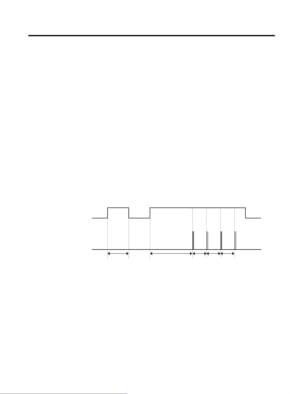
2-10. Door alarm
1. If the doors are left open for more than one minute, the buzzer sounds three 1/2-second tones at thirty second intervals for
four times.
2. If all the doors of freezing/cold storage room or home bar are closed during door open alarm, alarm is immediately turns
off.
2-11. Button selection buzzer bell
1. The DING sounds if you press any button on the front display.
- 25 -

MICOM FUNCTION
2-12. Automatic Defrost Signal
1. The beep will sound if you press the test button on the main PCB.
2. The regular cycle sounds three short beeps one second apart.
3. When you select the automatic defrost cycle, the alarm sounds three series of three short beeps one minute apart.
2-13. Defrost Function
1. Automatic defrost is performed whenever the compressor run time totals 71/2 hours.
2. At initial power-up, the defrost cycle will run when the total compressor runtime is 4
3. Defrost is completed when the defrost sensor temperature rises above 41°F (5°C) during the defrost cycle. The defrost
cycle will terminate if the defrost sensor temperature does not achieve 41°F (5°C) within two hours.
4. The defrost cycle will not operate if the defrost sensor fails.
2-14. Refrigerator compartment lamp automatically off
1. The refrigerator light is turned ON and OFF by the refrigerator door switch.
2. If the refrigerator light is on for more than 7 minutes, it will be turned off automatically. It will operate normally if you close
the door and re-open it.
1
/2
hours.
- 26 -
MICOM FUNCTION
POWER
ON
COMP
ON
F-FAN
&
C-FAN
ON
R-STEP
MOTOR
DAMPER
ON
OPTICHILL
STEP
DAMPER
MOTOR
ON
DEFROST
HEATER
OFF
DEFROST
HEATER
ON
DAMPER
&
DUCT DOOR
&
OPTICHILL
HEATER ON
DAMPER
&
DUCT DOOR
&
OPTICHILL
HEATER OFF
0.3
sec.
6.0
sec.
0.3
sec.
0.3
sec.
0.3
sec.
POWER
ON
0.3
sec.
PIPE
&
DISP'
HEATER
OFF
0.3
sec.
COMP
ON
0.3
sec.
F-FAN
&
C-FAN
ON
0.3
sec.
R-STEP
MOTOR
DAMPER
ON
0.3
sec.
OPTICHILL
STEP
DAMPER
MOTOR
ON
PIPE
&
DISP'
HEATER
ON
TEST
SWITCH
(PRESS
Once)
OTHER
LOAD
OFF
COMP
ON
F-FAN
&
C-FAN
ON
R-STEP
MOTOR
DAMPER
ON
OPTICHILL
STEP
DAMPER
MOTOR
CLOSE
TEST
SWITCH
(PRESS
2 Times)
COMP
OFF
F-FAN
&
C-FAN
OFF
FROST
REMOVAL
HEATER
ON
R-STEP
MOTOR
DAMPER
CLOSE
0.3
sec.
0.3
sec.
0.3
sec.
0.3
sec.
0.3
sec.
0.3
sec.
0.3
sec.
0.3
sec.
0.3
sec.
0.3
sec.
0.3
sec.
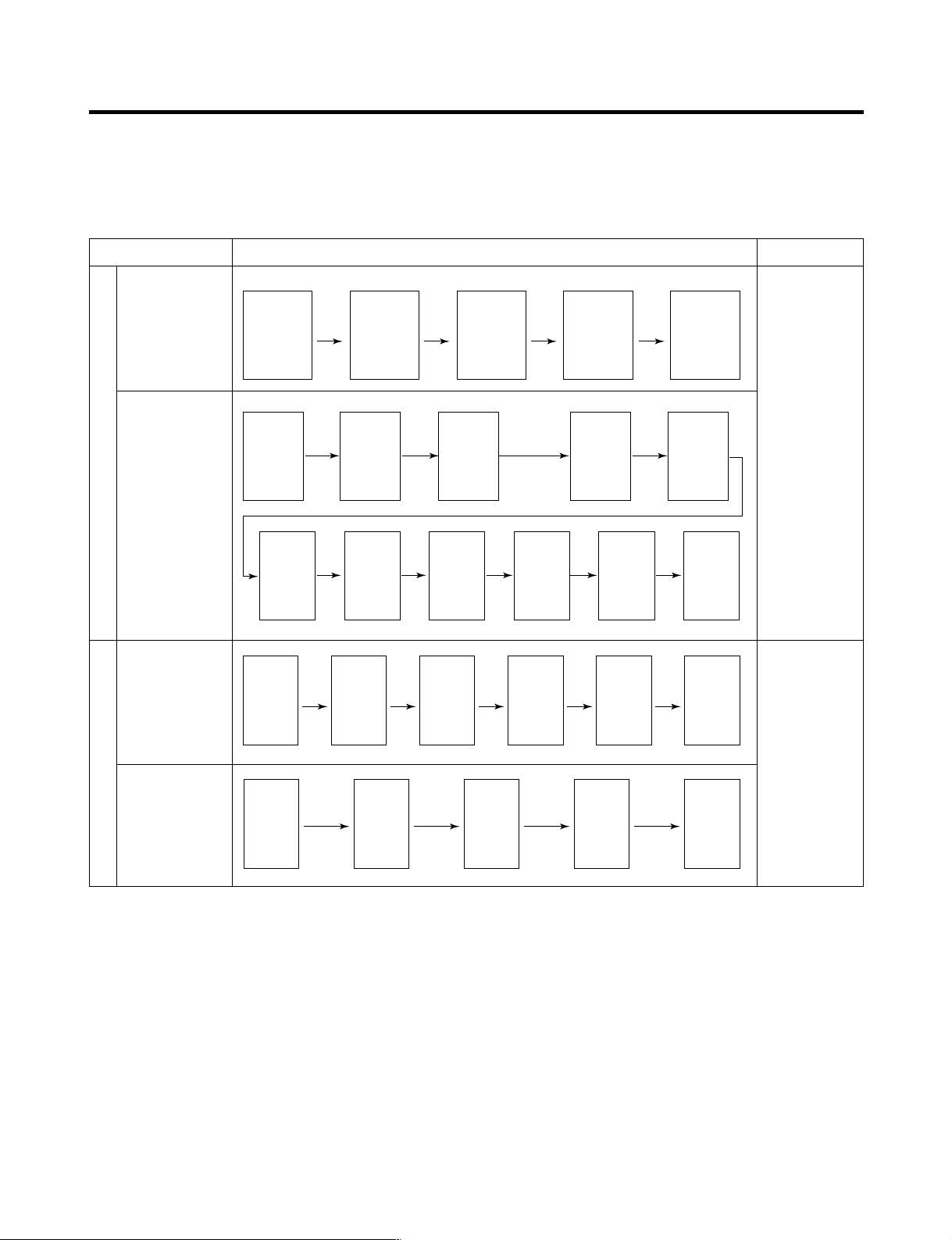
2-15. Sequential operation of components
Electromechanical parts of the appliance, such as the compressor, defrost heater, freezer fan, cooling fan, and damper
motor, are operated sequentially as shown in the chart below to prevent noise and circuit overload from everything starting
at once.
Function Load Operation Sequence Remark
When temperature
of a defrost sensor
becomes more
than 45°C
(initial setup,
movement)
In applying Initial power TEST MODE
When
temperature of a
defrost sensor
becomes less
than 45°C
(power failure,
service)
Test mode 1
(Compulsory
function)
Test mode 2
(Compulsory
defrost)
If error occurs
during operation,
initial operation is
not done.
Sequence of load
operation when
closing freezer
and refrigerator.
The refrigerator
will return to
normal operation
if you press the
test switch once
again while in
Test Mode 2 or if
the temperature
of the defrost
sensor surpasses
41°F (5°C). The
compressor will
run after the 7minute delay.
- 27 -
MICOM FUNCTION
ICEBEAM
COOLING
OFF
CUBE
FILTER
MONTH
ROOM TEMP
DISPENSER & KEY
F
WATER 5
4
3
2
1
CRUSH
F F
3 SECS
EXPRESS
(On)
DIGITAL CONTROL
FRZ TEMP REF TEMP
(Off)
JET
CUBE
FILTER RESET
HOLD 3SECS
ROOM TEMP
LOCK
DISPENSER & KEY
WATER
CRUSH
3 SECS
F
C
F
C
F
C
FILTER
C
E
A B D C
FAILURE CODE
INDICATION PART
E
A B D
FAILURE CODE
INDICATION PART
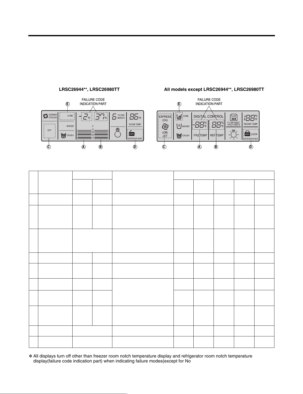
2-16. Failure Diagnosis
1. The failure diagnosis function indicates the area of a failure while the product is in operation.
2. When the appliance enters the failure mode, pressing buttons has no effect on the operation of the appliance.
3. If the error clears itself, the MICOM will reset and the appliance will operate as usual.
4. The failure code will be displayed as indicated in the drawings below. All other graphics and displays will be turned off.
LRSC26944**, LRSC26980TT All models except LRSC26944**, LRSC26980TT
●●
Failure code indication part
No. Item
1
Abnormal
freezer sensor
2
Abnormal refrigerator
Freezer notch
temperature
Refrigerator notch
temperature
display
Er FS
Er rS
display
Contents of failure
Freezer sensor short circuit
Refrigerator sensor1 short circuit
Compressor
ON for 15minutes /
OFF for 15minutes
sensor 1 (R1)
(Upper part in the
refrigerator
compartment)
3
Abnormal refrigerator
sensor 2 (R2)
Normal display
(Note 2)
Refrigerator sensor2 short circuit
(Middle part in the
refrigerator
compartment)
Abnormal defrost
4
Er dS
Abnormal short circuit
sensor
Failed defrosting
5
Er dH
Defrost heater, temperature fuse short
circuit, unplugged connector(indicated
4 hour later after trouble)
Abnormal freezing
6
BLDC motor
Er FF
Motor defect, hooked of lead wire
to fan, contact of structures with
fan, short or open of lead
Abnormal cooling
7
BLDC motor
Er CF
wire(there is no signal of BLDC
motor more than 115 seconds in
operation of fan motor)
Communication
8
Errors.
Er CO
Short or open of lead wire
connecting between main PCB
and display PCB, transmission tr
and receiving part
Abnormal
9
ambient sensor
Abnormal
10
Optichill sensor
✽ All displays turn off other than freezer room notch temperature display and refrigerator room notch temperature
display(failure code indication part) when indicating failure modes(except for Note1, Note2).
Normal display
(Note 1)
Normal display
(Note 2)
Ambient sensor short circuit
Optichill sensor short circuit
Product operation status in failure
Freezing
BLDC motor
Standard
Cooling
BLDC motor
●●
RPM
Standard
●●
●●
RPM
Standard
●●
●●
RPM
Standard
●●
●●
RPM
Standard
●●
●●
RPM
●●
●●
OFF
Standard
●●
OFF
RPM
Standard
●●
●●
RPM
●●
●●
●●
●●
●●
●●
Defrost
Heater
●●
●●
●●
No defrost
●●
●●
●●
●●
●●
●●
: Proper operation
Stepping
motor damper
●●
Full opening for
10 minutes/
Full closing for
15 minutes
●●
●●
●●
●●
●●
●●
●●
●●
- 28 -

MICOM FUNCTION
Note1) The freezer and refrigerator temperature displays are also used to display error codes. The exception is that when
the ambient temperature sensor fails, it shows Er in the ambient temperature display. All other display elements will
function normally.
Note2) The R2 sensor, Optichill sensor, and water tank sensor are not indicated in the error codes, but you can see these
errors by entering the test mode by pressing and holding the Freezer Temperature and Express/Jet Freezer buttons
simultaneously.
R2-sensor (middle room)
Optichill sensor
Water tank sensor
✻ LCD (LED) check function: LCD (LED) Press and hold the Express Freeze button and the Freezer Temperature
adjustment button to check the display. This will turn on the backlight and all display elements.
Release the buttons and the display will return to its usual state.
Normal: LED or LCD graphic on the (C) part turns on
Abnormal: LED or LCD graphic on the (C) part turns off
Normal: LED or LCD graphic on the (D) part turns on
Abnormal: LED or LCD graphic on the (D) part turns off
Normal: LEDs or LCDs graphic on the (E) part turns on
Abnormal: LEDs or LCDs graphic on the (E) part turns off
The other LED or
LCD Graphics
Turn On.
- 29 -
MICOM FUNCTION
EXPRESS
DIGITAL CONTROL
FRZ TEMP REF TEMP
JET
CUBE
FILTER RESET
HOLD 3SECS
ROOM TEMP
LOCK
DISPENSER & KEY
WATER
CRUSH
3 SECS
F
C
F
C
F
C
FILTER
5
4
3
2
1
ICEBEAM
COOLING
CUBE
FILTER
MONTH
ON
ROOM TEMP
DISPENSER & KEY
WATER 5
4
3
2
1
CRUSH
3 SECS
EXPRESS FRZ
F
C
F
C
LOCK
F
C
JET
3 SECS
FILTER LIGHT
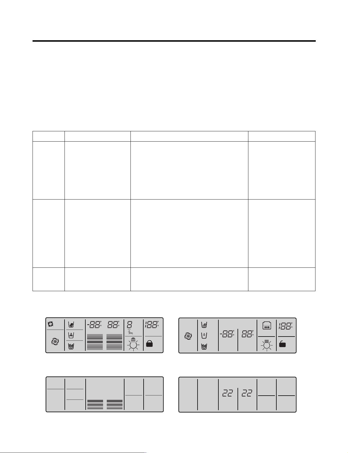
2-17. Test Function
1. The test function is a self-diagnostic system designed to detect problems early and to make diagnosis and repair easier
and quicker.
2. The test button is on the main PCB. Test mode can run for up to 2 hours and will then default to the normal operation
mode if not reset manually.
3. The function buttons are inoperable when the refrigerator is in test mode.
4. When you have finished using the test mode, reset the appliance manually by unplugging it for several seconds.
5. If nonconforming contents such as sensor failure are found during performance of test mode, release the test mode and
display the failure code.
6. The test button is inoperable if the display is showing failure codes. Reset the appliance manually to use the test button.
Mode Operation Contents Remarks
Test 1
Test 2
Normal
Status
Press test button once
(strong cold mode)
Press test button once at
the test mode 1 status
(forced defrost mode)
Press test button once at
the test mode 2 status
1. Continuous operation of compressor
2. Continuous operation of freezing BLDC motor
(high-speed RPM) and cooling BLDC motor
3. Defrost heater turns off
4. Stepping motor damper is completely opened
(baffle open)
5. Optichill stepping motor damper is completely
closed.
6. All display LEDs or LCD graphics turn on.
1. Compressor OFF
2. Freezing BLDC motor and cooling BLDC
motor turn off
3. Defrost heater turns on
4. Stepping motor damper is completely closed
(baffle close)
5. Optichill stepping motor damper is completely
closed.
6. All display LEDs or LCD graphics turn off.
Except for (A), (B) LCD graphic.
Except for (A): 22 (B): 22 LEDs.
Return to the initial status.
TEST MODE1 STATUS DISPLAY
Freezer fan is off when
door is open.
Return to the normal mode
when the defrost sensor is
above +5°C
Compressor will operate
after delay for 7 minutes
TEST MODE2 STATUS DISPLAY
- 30 -
 Loading...