

LG LRSC21935xx Service Manual
CAUTION
PLEASE READ CAREFULLY THE SAFETY PRECAUTIONS OF THIS BOOK
BEFORE CHECKING OR OPERATING THE REFRIGERATOR.
REFRIGERATOR
SERVICE MANUAL
MODEL:
COLOR: SUPER WHITE
TITANIUM
http://biz.lgservice.com

CONTENTS
WARNINGS AND PRECAUTIONS FOR SAFETY ................................................................................................................ 3
SPECIFICATIONS................................................................................................................................................................... 4
PARTS IDENTIFICATION ..................................................................................................................................................... 12
HOW TO INSTALL THE REFRIGERATOR .......................................................................................................................... 18
HOW TO ADJUST DOOR HEIGHT OF THE REFRIGERATOR ........................................................................................ 18
HOW TO INSTALL WATER PIPE........................................................................................................................................19
HOW TO CONTROL THE AMOUNT OF WATER SUPPLIED TO THE ICEMAKER ......................................................... 23
MICOM FUNCTION .............................................................................................................................................................. 25
EXPLATION FOR MICOM CIRCUIT..................................................................................................................................... 34
EXPLANATION FOR PWB CIRCUIT ..................................................................................................................................34
COMPENSATION CIRCUIT FOR WEAK-COLD, OVER-COLD AT FREEZING ROOM.....................................................49
PWB PARTS DRAWING AND LIST ....................................................................................................................................53
PWB CIRCUIT DIAGRAM ...................................................................................................................................................63
ICE MAKER AND DISPENSER OPERATION PRINCIPLE AND REPAIR METHOD.......................................................... 67
WORKING PRINCIPLES.....................................................................................................................................................67
FUNCTION OF ICE MAKER ...............................................................................................................................................68
ICE MAKER TROUBLESHOOTING....................................................................................................................................71
ICE MAKER CIRCUIT PART ...............................................................................................................................................72
CIRCUIT................................................................................................................................................................................ 73
TROUBLE DIAGNOSIS........................................................................................................................................................ 75
TROUBLE SHOOTING ...................................................................................................................................................... 75
FAULTS .............................................................................................................................................................................. 85
COOLING CYCLE HEAVY REPAIR ................................................................................................................................. 102
HOW TO DEAL WITH CLAIMS........................................................................................................................................ 109
HOW TO DISASSEMBLE AND ASSEMBLE ..................................................................................................................... 114
DOOR ............................................................................................................................................................................... 114
HANDLE ........................................................................................................................................................................... 115
SHROUD, GRILLE FAN ................................................................................................................................................... 115
ICEMAKER ....................................................................................................................................................................... 115
DISPENSER ..................................................................................................................................................................... 116
WATER TANK AND WATER LINE.................................................................................................................................... 118
HOME BAR....................................................................................................................................................................... 118
EXPLODED VIEW............................................................................................................................................................... 119
REPLACEMENT PARTS LIST ........................................................................................................................................... 128
- 2 -

WARNINGS AND PRECAUTIONS FOR SAFETY
Please observe the following safety precautions in order to
use safely and correctly the refrigerator and to prevent
accident and danger during repair.
1. Be care of an electric shock. Disconnect power cord
from wall outlet and wait for more than three minutes
before replacing PWB parts. Shut off the power
whenever replacing and repairing electric components.
2. When connecting power cord, please wait for more than
five minutes after power cord was disconnected from the
wall outlet.
3. Please check if the power plug is pressed down by the
refrigerator against the wall. If the power plug was
damaged, it may cause fire or electric shock.
4. If the wall outlet is over loaded, it may cause fire. Please
use its own individual electrical outlet for the refrigerator.
5. Please make sure the outlet is properly earthed,
particularly in wet or damp area.
8. Do not fray, damage, machine, heavily bend, pull out,
or twist the power cord.
9. Please check the evidence of moisture intrusion in the
electrical components. Replace the parts or mask it
with insulation tapes if moisture intrusion was
confirmed.
10. Do not touch the icemaker with hands or tools to
confirm the operation of geared motor.
11. Do not let the customers repair, disassemble, and
reconstruct the refrigerator for themselves. It may
cause accident, electric shock, or fire.
12. Do not store flammable materials such as ether,
benzene, alcohol, chemicals, gas, or medicine in the
refrigerator.
13. Do not put flower vase, cup, cosmetics, chemicals,
etc., or container with full of water on the top of the
refrigerator.
6. Use standard electrical components when replacing
them.
7. Make sure the hook is correctly engaged.
Remove dust and foreign materials from the housing
and connecting parts.
14. Do not put glass bottles with full of water into the
freezer. The contents shall freeze and break the glass
bottles.
15. When you scrap the refrigerator, please disconnect the
door gasket first and scrap it where children are not
accessible.
- 3 -
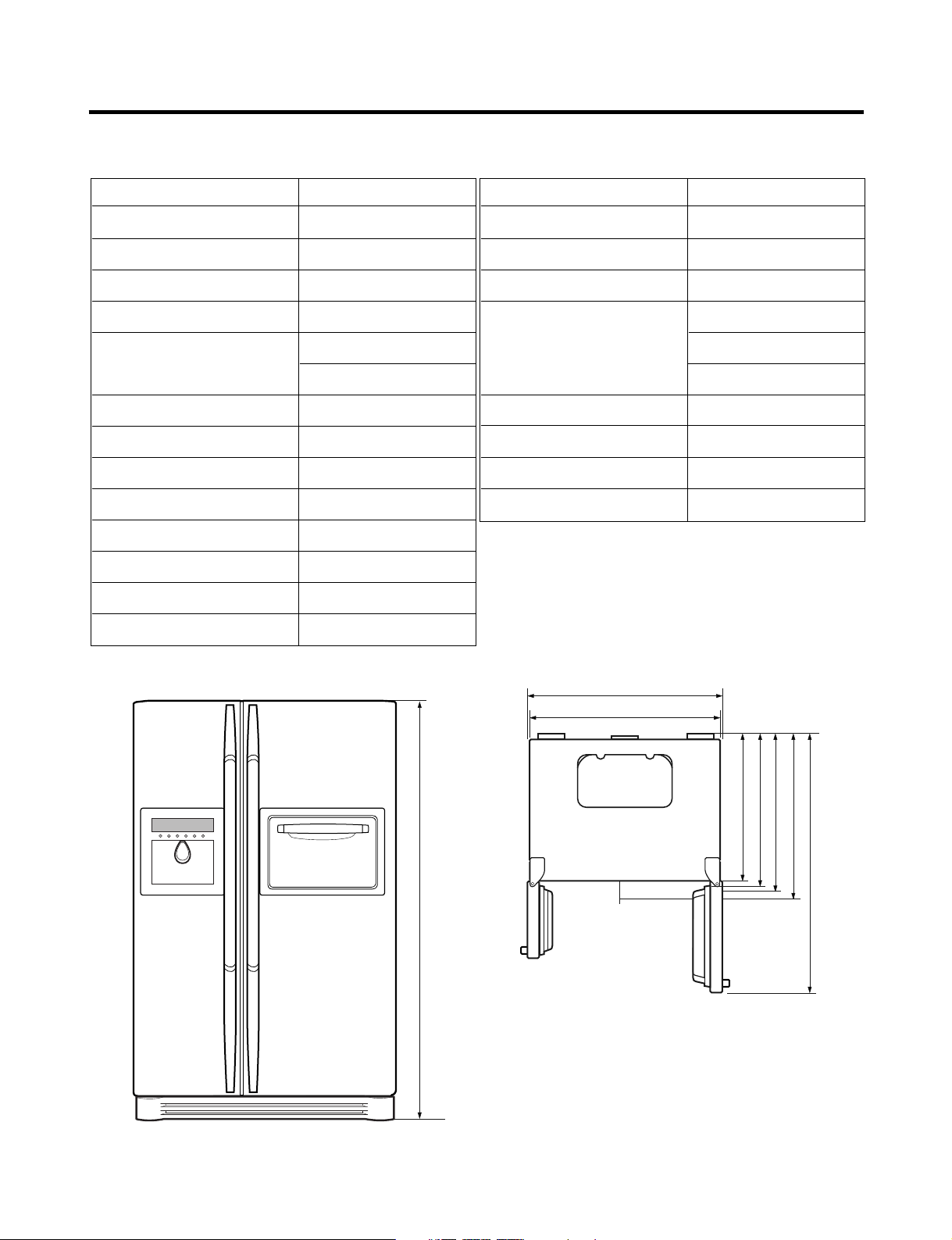
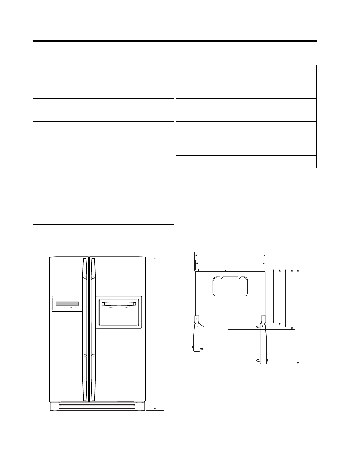
SPECIFICATIONS
1. Ref No. : GR-P257
ITEMS SPECIFICATIONS
DIMENSIONS (mm) 894(W)X875(D)X1753(H)
NET WEIGHT (kg) 128
COOLING SYSTEM Fan Cooling
TEMPERATURE CONTROL Micom Control
DEFROSTING SYSTEM Full Automatic
Heater Defrost
INSULATION Cyclo-Pentane
COMPRESSOR P.T.C. Starting Type
EVAPORATOR Fin Tube Type
CONDENSER Wire Condenser
REFRIGERANT R134a (180g)
LUBRICATING OIL FREOL @10G (310 cc)
CAPILLARY TUBE ID 0.83
DRIER MOLECULAR SIEVE XH-7
ITEMS SPECIFICATIONS
FIRST DEFROST 4 - 5 Hours
DEFROST CYCLE 13 - 15 Hours
DEFROSTING DEVICE Heater, Sheath
ANTI SWEAT HEATER Dispenser Duct Door Heater
Dispenser Heater
Home Bar Heater
ANTI-FREEZING HEATER Damper Heater
FREEZER LAMP 40W (1 EA)
REFRIGERATOR LAMP 40W (1 EA)
DISPENSER LAMP 15W (1 EA)
1753
948
894
687
747
796
875
1220.5
<Front View> <Plane View>
- 4 -

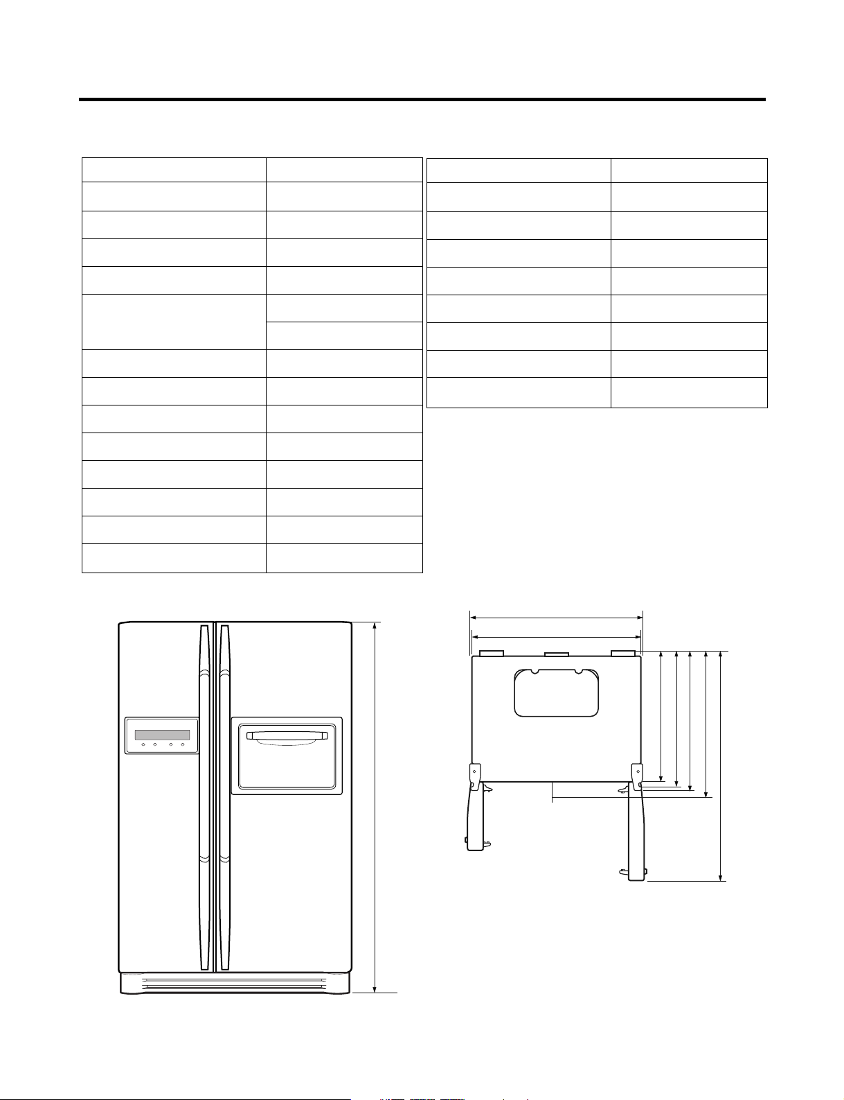
SPECIFICATIONS
2. Ref No. : GR-P217
ITEMS SPECIFICATIONS
DIMENSIONS (mm) 894(W)X790(D)X1753(H)
NET WEIGHT (kg) 120
COOLING SYSTEM Fan Cooling
TEMPERATURE CONTROL Micom Control
DEFROSTING SYSTEM Full Automatic
Heater Defrost
INSULATION Cyclo-Pentane
COMPRESSOR P.T.C. Starting Type
EVAPORATOR Fin Tube Type
CONDENSER Wire Condenser
REFRIGERANT R134a (180g)
LUBRICATING OIL FREOL @10G (310 cc)
CAPILLARY TUBE ID 0.83
DRIER MOLECULAR SIEVE XH-7
ITEMS SPECIFICATIONS
FIRST DEFROST 4 - 5 Hours
DEFROST CYCLE 13 - 15 Hours
DEFROSTING DEVICE Heater, Sheath
ANTI SWEAT HEATER Dispenser Duct Door Heater
Dispenser Heater
Home Bar Heater
ANTI-FREEZING HEATER Damper Heater
FREEZER LAMP 40W (1 EA)
REFRIGERATOR LAMP 40W (1 EA)
DISPENSER LAMP 15W (1 EA)
1753
948
894
602
662
711
790
1135.5
<Front View> <Plane View>
- 5 -
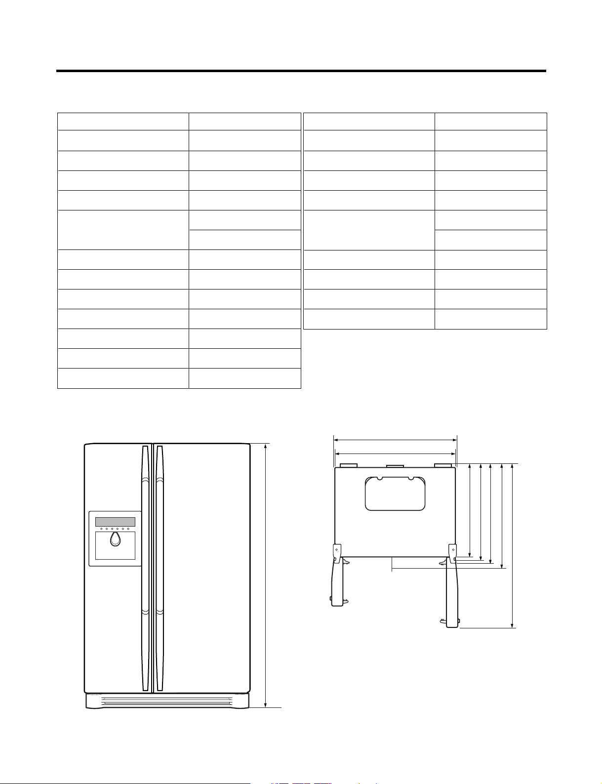
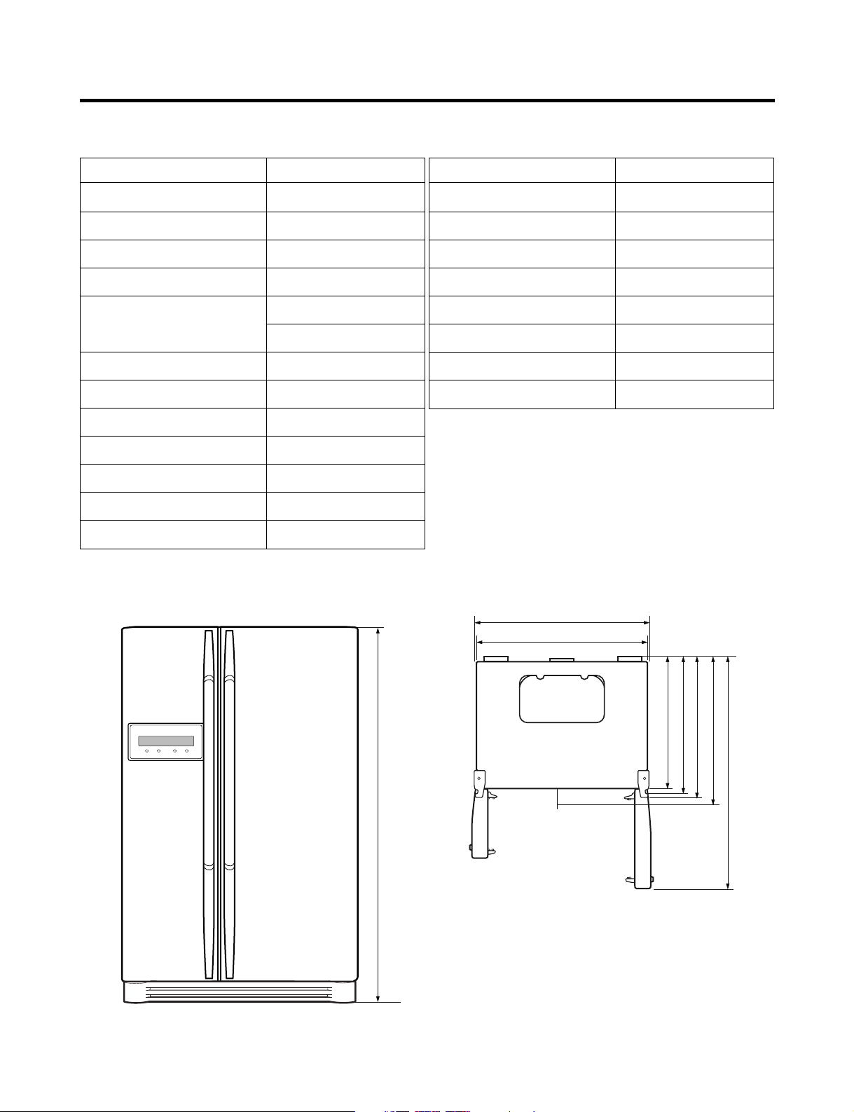
SPECIFICATIONS
3. Ref No. : GR-L257
ITEMS SPECIFICATIONS
DIMENSIONS (mm) 894(W)X875(D)X1753(H)
NET WEIGHT (kg) 125
COOLING SYSTEM Fan Cooling
TEMPERATURE CONTROL Micom Control
DEFROSTING SYSTEM Full Automatic
Heater Defrost
INSULATION Cyclo-Pentane
COMPRESSOR P.T.C. Starting Type
EVAPORATOR Fin Tube Type
CONDENSER Wire Condenser
REFRIGERANT R134a (180g)
LUBRICATING OIL FREOL @10G (310 cc)
CAPILLARY TUBE ID 0.83
ITEMS SPECIFICATIONS
DRIER MOLECULAR SIEVE XH-7
FIRST DEFROST 4 - 5 Hours
DEFROST CYCLE 13 - 15 Hours
DEFROSTING DEVICE Heater, Sheath
ANTI SWEAT HEATER Dispenser Duct Door Heater
Dispenser Heater
ANTI-FREEZING HEATER Damper Heater
FREEZER LAMP 40W (1 EA)
REFRIGERATOR LAMP 40W (1 EA)
DISPENSER LAMP 15W (1 EA)
1753
948
894
687
747
796
875
1220.5
<Front View> <Plane View>
- 6 -
SPECIFICATIONS
- 7 -
ITEMS SPECIFICATIONS
DIMENSIONS (mm) 894(W)X790(D)X1753(H)
NET WEIGHT (kg) 117
COOLING SYSTEM Fan Cooling
TEMPERATURE CONTROL Micom Control
DEFROSTING SYSTEM Full Automatic
Heater Defrost
INSULATION Cyclo-Pentane
COMPRESSOR P.T.C. Starting Type
EVAPORATOR Fin Tube Type
CONDENSER Wire Condenser
REFRIGERANT R134a (180g)
LUBRICATING OIL FREOL @10G (310 cc)
CAPILLARY TUBE ID 0.83
<Front View> <Plane View>
4. Ref No. : GR-L217
ITEMS SPECIFICATIONS
DRIER MOLECULAR SIEVE XH-7
FIRST DEFROST 4 - 5 Hours
DEFROST CYCLE 13 - 15 Hours
DEFROSTING DEVICE Heater, Sheath
ANTI SWEAT HEATER Dispenser Duct Door Heater
Dispenser Heater
ANTI-FREEZING HEATER Damper Heater
FREEZER LAMP 40W (1 EA)
REFRIGERATOR LAMP 40W (1 EA)
DISPENSER LAMP 15W (1 EA)
1753
948
894
602
662
711
790
1135.5
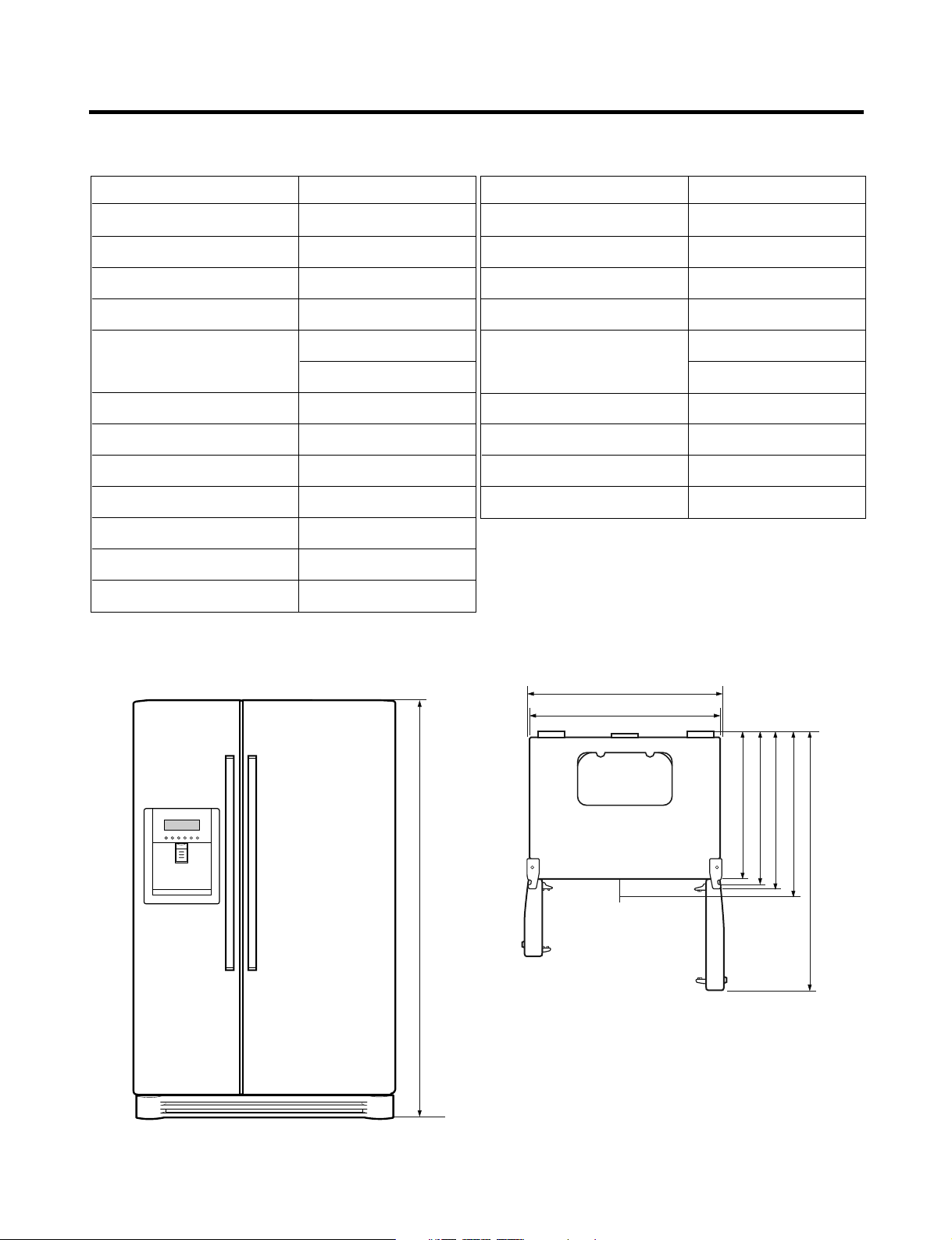
SPECIFICATIONS
1. Ref No. : GR-C257
ITEMS SPECIFICATIONS
DIMENSIONS (mm) 894(W)X875(D)X1753(H)
NET WEIGHT (kg) 117
COOLING SYSTEM Fan Cooling
TEMPERATURE CONTROL Micom Control
DEFROSTING SYSTEM Full Automatic
Heater Defrost
INSULATION Cyclo-Pentane
COMPRESSOR P.T.C. Starting Type
EVAPORATOR Fin Tube Type
CONDENSER Wire Condenser
REFRIGERANT R134a (180g)
LUBRICATING OIL FREOL @10G (310 cc)
CAPILLARY TUBE ID 0.83
DRIER MOLECULAR SIEVE XH-7
ITEMS SPECIFICATIONS
FIRST DEFROST 4 - 5 Hours
DEFROST CYCLE 13 - 15 Hours
DEFROSTING DEVICE Heater, Sheath
ANTI SWEAT HEATER Home Bar Heater
ANTI-FREEZING HEATER Damper Heater
FREEZER LAMP 40W (1 EA)
REFRIGERATOR LAMP 40W (1 EA)
DISPENSER LAMP 15W (1 EA)
1753
948
894
687
747
796
875
1220.5
<Front View> <Plane View>
- 8 -
SPECIFICATIONS
2. Ref No. : GR-C217
ITEMS SPECIFICATIONS
DIMENSIONS (mm) 894(W)X790(D)X1753(H)
NET WEIGHT (kg) 112
COOLING SYSTEM Fan Cooling
TEMPERATURE CONTROL Micom Control
DEFROSTING SYSTEM Full Automatic
Heater Defrost
INSULATION Cyclo-Pentane
COMPRESSOR P.T.C. Starting Type
EVAPORATOR Fin Tube Type
CONDENSER Wire Condenser
REFRIGERANT R134a (180g)
LUBRICATING OIL FREOL @10G (310 cc)
CAPILLARY TUBE ID 0.83
CDRIER MOLECULAR SIEVE XH-7
ITEMS SPECIFICATIONS
FIRST DEFROST 4 - 5 Hours
DEFROST CYCLE 13 - 15 Hours
DEFROSTING DEVICE Heater, Sheath
ANTI SWEAT HEATER Home Bar Heater
ANTI-FREEZING HEATER Damper Heater
FREEZER LAMP 40W (1 EA)
REFRIGERATOR LAMP 40W (1 EA)
DISPENSER LAMP 15W (1 EA)
1753
948
894
602
662
711
790
1135.5
<Front View> <Plane View>
- 9 -
SPECIFICATIONS
3. Ref No. : GR-B257
ITEMS SPECIFICATIONS
DIMENSIONS (mm) 894(W)X875(D)X1753(H)
NET WEIGHT (kg) 114
COOLING SYSTEM Fan Cooling
TEMPERATURE CONTROL Micom Control
DEFROSTING SYSTEM Full Automatic
Heater Defrost
INSULATION Cyclo-Pentane
COMPRESSOR P.T.C. Starting Type
EVAPORATOR Fin Tube Type
CONDENSER Wire Condenser
REFRIGERANT R134a (180g)
LUBRICATING OIL FREOL @10G (310 cc)
CAPILLARY TUBE ID 0.83
ITEMS SPECIFICATIONS
DRIER MOLECULAR SIEVE XH-7
FIRST DEFROST 4 - 5 Hours
DEFROST CYCLE 13 - 15 Hours
DEFROSTING DEVICE Heater, Sheath
ANTI-FREEZING HEATER Damper Heater
FREEZER LAMP 40W (1 EA)
REFRIGERATOR LAMP 40W (1 EA)
DISPENSER LAMP 15W (1 EA)
1753
948
894
687
747
796
875
1220.5
<Front View> <Plane View>
- 10 -

SPECIFICATIONS
4. Ref No. : GR-B217
ITEMS SPECIFICATIONS
DIMENSIONS (mm) 894(W)X790(D)X1753(H)
NET WEIGHT (kg) 109
COOLING SYSTEM Fan Cooling
TEMPERATURE CONTROL Micom Control
DEFROSTING SYSTEM Full Automatic
Heater Defrost
INSULATION Cyclo-Pentane
COMPRESSOR P.T.C. Starting Type
EVAPORATOR Fin Tube Type
CONDENSER Wire Condenser
REFRIGERANT R134a (180g)
LUBRICATING OIL FREOL @10G (310 cc)
CAPILLARY TUBE ID 0.83
ITEMS SPECIFICATIONS
DRIER MOLECULAR SIEVE XH-7
FIRST DEFROST 4 - 5 Hours
DEFROST CYCLE 13 - 15 Hours
DEFROSTING DEVICE Heater, Sheath
ANTI-FREEZING HEATER Damper Heater
FREEZER LAMP 40W (1 EA)
REFRIGERATOR LAMP 40W (1 EA)
DISPENSER LAMP 15W (1 EA)
1753
948
894
602
662
711
790
1135.5
<Front View> <Plane View>
- 11 -

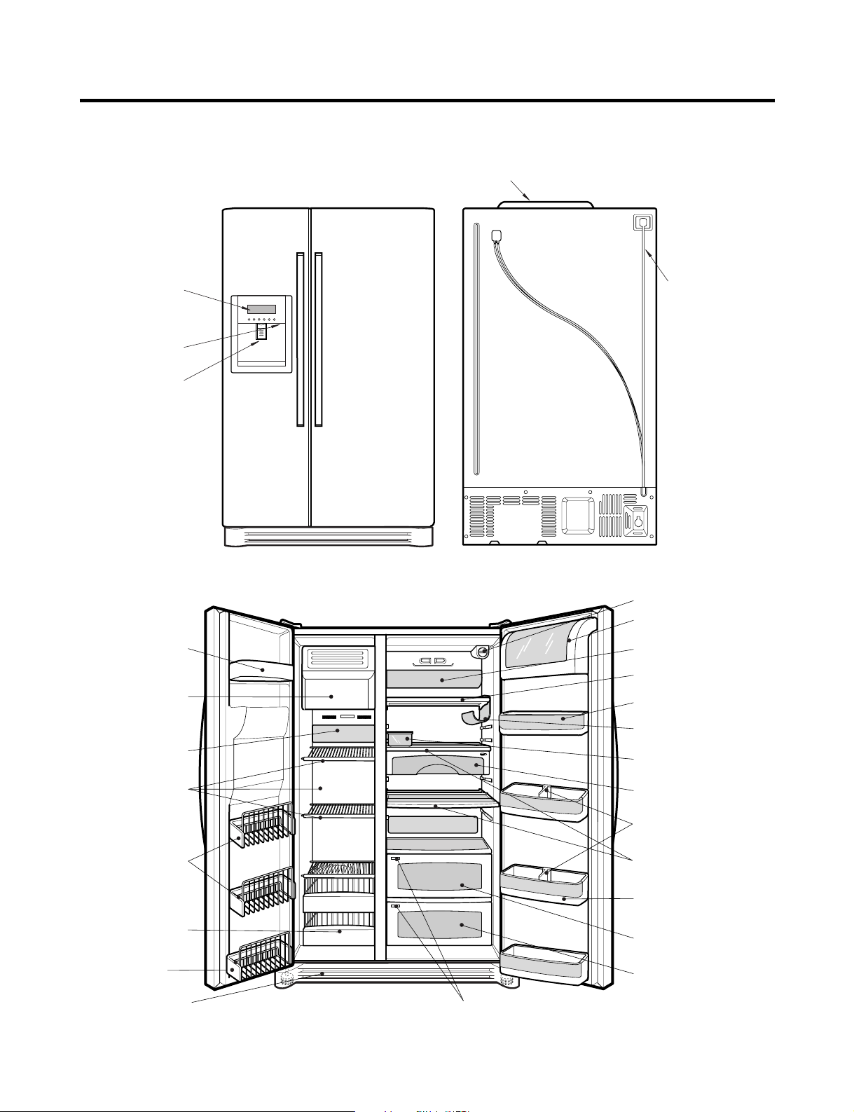
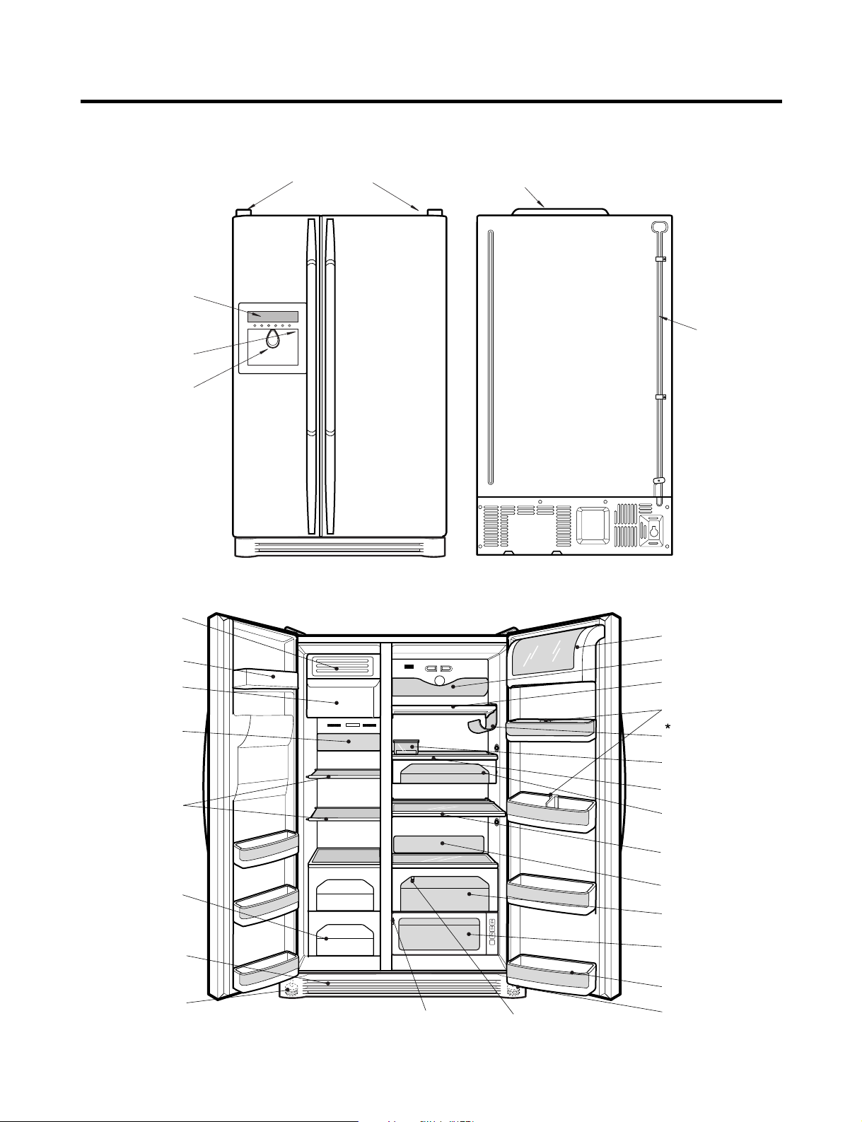
PARTS IDENTIFICATION
Select
Meat
Cheese
Veg.
Conversion Switch
(Meats/Vegetables)
Humidity Switch
Freezer
Compartment
Refrigerator
Compartment
Cover PWB
Cover, Lamp-R/U
Shelf
Egg Box
Snack Corner
(Optional)
Vegetable Box
(1 or 2)
Miracle Zone
(Optional)
Adjust Screw
Basket
Cover Home Bar
Cover Lamp-R/L
Shelf
Folding Shelf
Guide Bottle
Wine Rack
Water Tube
Cover,Lamp -F
Shelf -F
Drawer
Cover Lower
Adjust Screw
Cover, Dairy
Ice Bank
Assembly
Ice Shelf
Assembly
Door Rack
Home Bar
Frame Display
Dispenser Lamp
Ice & Water
Dispenser Button
Cover Hinge
1. Ref No. : GR-P257, GR-P217
- 12 -

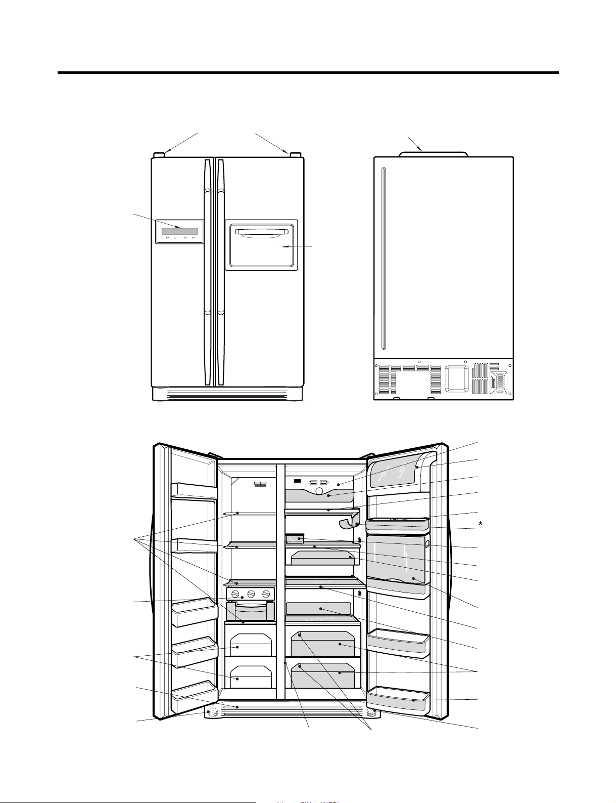
PARTS IDENTIFICATION
Select
Meat
Cheese
Veg.
Home Bar
Frame Display
Dispenser Lamp
Ice & Water
Dispenser Button
Cover Hinge
Cover PWB
Folding Shelf
Miracle Zone
(Optional)
Conversion Switch
(Meats/Vegetables)
Humidity Switch
Freezer
Compartment
Refrigerator
Compartment
Cover, Lamp-R/U
Shelf
Egg Box
Snack Corner
(Optional)
Vegetable Box
(1 or 2)
Adjust Screw
Basket
Cover Home Bar
Cover Lamp-R/L
Shelf
Guide Bottle
Wine Rack
Shelf -F
Drawer
Cover Lower
Adjust Screw
Cover, Dairy
Cover,Lamp -F
Ice Bank
Assembly
Ice Shel
Assembly
Door Rack
2. Ref No. : GR-P257, GR-P217
- 13 -
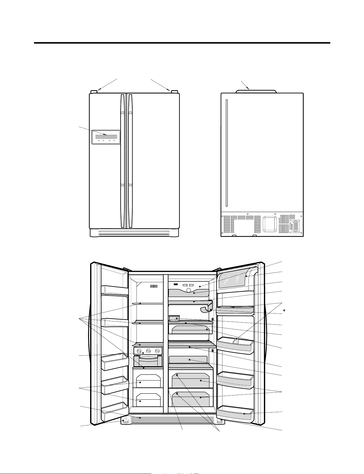
PARTS IDENTIFICATION
Frame Display
Dispenser Lamp
Ice & Water
Dispenser Button
PWB Cover
3. Ref No. : GR-L257, GR-L217
Water Tubes
Door Rack
Automatic
Icemaker
Lamp
Shelf
Door Rack
Drawer
(Wire/Plastic)
Door Rack
Lower Cover
Freezer
Compartment
Refrigerator
Compartment
Humidity Switch
Water Filter
Dairy Product Corner
Lamp
Shelf
Door Rack
Wine Holder
Egg Box
Snack Drawer
Bottle Guide
Shelf
Door Rack
Vegetable Drawer
Vegetable Drawer
/Meat Drawer
- 14 -
PARTS IDENTIFICATION
Select
Meat
Cheese
Veg.
Frame Display
Dispenser Lamp
Ice & Water
Dispenser Button
Cover Hinge
Cover PWB
Water Tube
Miracle Zone
(Optional)
Humidity Switch
Freezer
Compartment
Refrigerator
Compartment
Conversion Switch
(Meats/Vegetables)
Cover, Lamp-R/U
Shelf
Egg Box
Snack Corner
(Optional)
Vegetable Box
(1 or 2)
Adjust Screw
Basket
Cover Lamp-R/L
Shelf
Folding Shelf
Guide Bottle
Wine Rack
Shelf -F
Drawer
Cover Lower
Adjust Screw
Cover, Dairy
Cover,Lamp -F
Ice Bank
Assembly
Ice Shelf
Assembly
Door Rack
4. Ref No. : GR-L257, GR-L217
- 15 -
PARTS IDENTIFICATION
Cover PWB
Cover Hinge
Home Bar
Frame Display
Cover, Lamp-R/U
Shelf
Egg Box
Snack Corner
(Optional)
Vegetable Box
(2 or 3)
Adjust Screw
Basket
Cover Home Bar
Shelf
Folding Shelf
Cover, Lamp-R/L
Guide Bottle
Wine Rack
Cover, Dairy
Control Box,R
Conversion Switch
(Meats/Vegetables)
Humidity Switch
Freezer
Compartment
Refrigerator
Compartment
Cover Lower
Adjust Screw
Shelf -F
Drawer
Triple & Movable
Twist Ice Tray
1. Ref No. : GR-C257, GR-C217
- 16 -
PARTS IDENTIFICATION
Cover PWB
Cover Hinge
Frame Display
Cover, Lamp-R/U
Shelf
Egg Box
Snack Corner
(Optional)
Vegetable Box
(2 or 3)
Adjust Screw
Basket
Shelf
Folding Shelf
Cover, Lamp-R/L
Guide Bottle
Wine Rack
Cover, Dairy
Control Box,R
Conversion Switch
(Meats/Vegetables)
Humidity Switch
Freezer
Compartment
Refrigerator
Compartment
Cover Lower
Adjust Screw
Shelf -F
Drawer
Triple & Movable
Twist Ice Tray
3. Ref No. : GR-B257, GR-B217
- 17 -
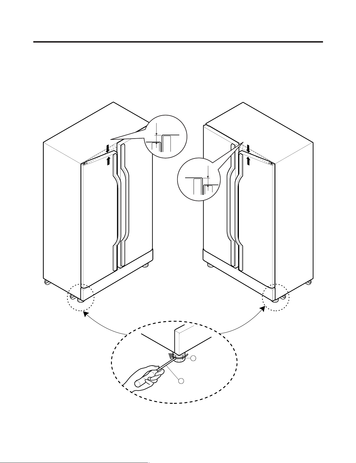
HOW TO INSTALL REFRIGERATOR
Adjusting
Screw
Driver
Height
Difference
Height
Difference
Height
Difference
Height
Difference
1
2
1. How to Adjust Door Height of Refrigerator
■ Make the refrigerator level first. (If the refrigerator is not installed on the flat floor, the height of freezer and refrigerator
door may not be the same.)
1. If the height of freezer door is lower than that of
refrigerator compartment :
2. If the height of freezer door is higher than that of
refrigerator compartment :
Insert a driver into the groove of adjusting screw
and rotate driver in arrow direction (clockwise) until the
refrigerator becomes horizontal.
- 18 -
Insert a driver into the groove of adjusting screw
and rotate driver in arrow direction (clockwise) until the
refrigerator becomes horizontal.
HOW TO INSTALL REFRIGERATOR
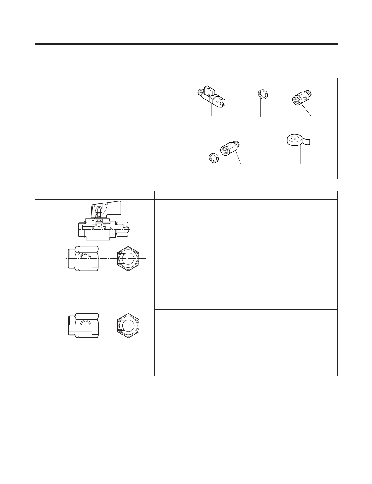
Valve Feed Rubber, Packing Connector, Pipe
Tape, TeflonConnector, Pipe
2. How to Install Water Pipe
■ Before Installation
1. The icemaker requires the water pressure of 1.5 -
8.5kgf/cm
180cc with water for 3 seconds)
2. Install booster pump where the city water pressure is
below 1.5kgf/cm
dispenser.
3. The total length of water pipe shall be less than 12m. Do
not bend the pipe at right angle. If the length is more
than 12m, there will be troubles on water supply due to
water pressure drop.
4. Please install water pipe where there is no heat around.
Class. Shape and Spec. Nomenclature P/No Remarks
Conve-
2
. (It is acceptable if city water fills a cup of
2
for normal operation of water and ice
Valve Feed 5221JA3001A Common Use
2-1. When connecting directly to the water tap.
■ Please confirm the following installation parts.
rtible
Water
Valve
Water
Connector
Connector, (MECH) Pipe 4932JA3003B
Connector, (MECH) Pipe 4932JA3003A
Conversion Connector(3/4") 6631JA3004A
No Holes
Balance Conector(3/4") 6631JA3004B
Packing(ø24x3t) 3920JA3001B
Conversion Connector(W25) 6631JA3004C
No Holes
Balance Conectoor(W25) 6631JA3004D
Packing(ø23x3t) 3920JA3001A
Connector, (MECH) Pipe 4932JA3003C
Conversion Connector(W28) 6631JA3004E
No Holes
Balance Conector(W28) 6631JA3004F
Packing(ø26x3t) 3920JA3001C
Connector, (MECH) Pipe 4932JA3003D
Conversion Connector(1/2") 6631JA3004G No Holes
Balance Conector(1/2") 6631JA3004H
Packing(ø19x3t) 3920JA3001D
- 19 -
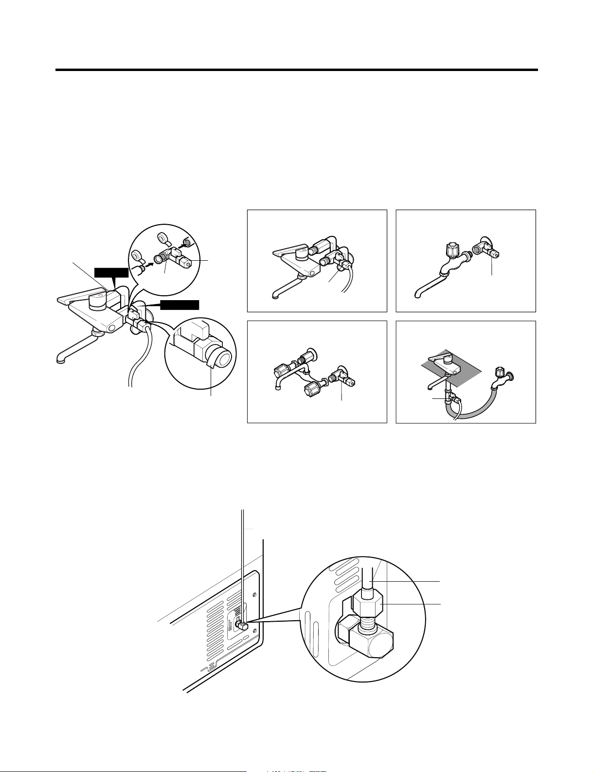
HOW TO INSTALL REFRIGERATOR
Single Lever Type Faucet
(general)
Feed
Valve
General Type
Feed
Valve
Two Hands Type Faucet Single Lever Type Faucet (one
hole, tech type and hand spray)
Feed
Valve
Feed
Valve
Pipe Connector B
Hot Water
Pipe Connector A
Feed
Valve
Cold Water
How to wind
Sealing Tapes.
Water Tube
Water Tube
Nut
1. Connection of Pipe Connector A and B.
1) Turn off main valve of water pipe.
2) Disconnect water tap from piping by loosening nuts.
3) Connect pipe connector A and B to piping after sealing
the pipe connector with sealing tapes.
4) Connect feed valve to pipe connector A.
5) If there is only one tap water pipe, connect pipe
connector A only and install feed pipe.
Caution : • Feed pipe should be connected to cold water
line. If it is connected to hot water line, trouble
may occur.
• Please check rubber packing when connecting
feed pipe.
2. Water Supply
1) After the installation of feed water, plug the refrigerator
to the earthered wall outlet, press the water dispenser
button for 2 - 3 minutes, and confirm that the water
comes out.
2) Check leakage at connecting part, then arrange water
tube and locate the refrigerator at its regular place if
there is no leaking.
- 20 -
HOW TO INSTALL REFRIGERATOR
Water Tube
Nut
Inlet
Outlet
Fixing Plate Fixing Plate
Fixing Cable
Water
Filter
Filter Inlet
Feed Valve
Hot Water
Cold Water
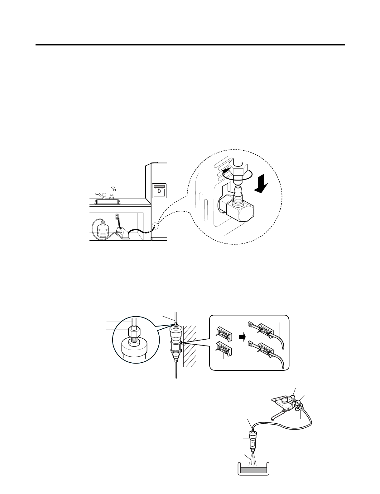
3. When customer uses bottled water.
*If customer wants to use bottled water, extra pump should be installed as shown below.
1. The pump system should not be on the floor (it may cause noise and vibration). Securely fasten the inlet and outlet
nuts of pump.
2. If there is any leakage after installation, cut the water tube at right angle and reassemble.
3. When put the water tube end into the bottle, leave a clearance between bottle bottom and water tube end.
4 Check water coming out and any leakage.
Caution : • If feed tube is more than 4m, less water will come out due to pressure drops.
• Use standard feed tube to prevent leaking.
■ Outternal Filter
1. Filter Fixation
1) Connect feed tube to the filter outlet and water valve connecting tube.
2) Fix the filter at proper place around the sink where it is easy to replace the filter and to receive the cleaning water.
Please consider the length of tube shall be less than 12m when locating filter.
3) When fixing the filter, use fixing plate and cable depending on the surrounding conditions.
2. Filter Cleaning
1) Connect feed tube to the inlet of feed valve and filter.
2) Clean the main valve and feed valve with water for at
least one minute until clean water comes out.
- 21 -
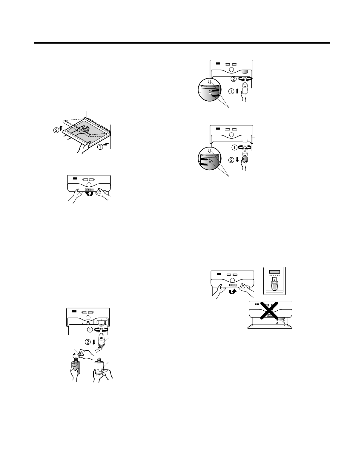
■ Install Water Filter (Applicable to some models only)
■ Before Installing water filter
1. Before installing the filter, take out the top shelf of the
refrigerator after tilting it to the direction () and lifting it
to the direction () and move it to the lower part.
2. Remove the lamp cover by pressing the protrusion
under the cover and pulling the cover to the front.
■ Installing water filter
1. Initial installation of water filter
Remove the filter substitute cap by turning it
counterclockwise () by 90 degrees and pulling it down.
Note : Keep it safe to use it later when you do not use the
filter.
Remove the red cap from the filter and attach the
sticker. Insert the upper part of the filter () after
aligning with the guideline marked on the control box,
and fasten it by turning it clockwise by 90 degrees.
Note : Check that the guideline and the fastening
indication line are aligned.
2. Replacement of water filter
While holding the lower part of the filter, turn it
counterclockwise () by 90 degrees and pull it down.
Note : Check that the guideline and the loosening
indication line are aligned.
■ After installing water filter
Reassemble the lamp cover and the top shelf of the
refrigerator. To place the top shelf of the refrigerator, raise
the front part of the shelf a bit so that the hook of the shelf
is fit into the groove.
In order to clean the water filter system, drain water for
about 3 min.
Note : Then open the door of the refrigerator and check for
water droppings on the shelf under the filter.
HOW TO INSTALL REFRIGERATOR
- 22 -
Control box
Aligning with the guide line
and the fastening indication line
Control box
Aligning with the guide line
and the loosening indication line
Separation
of red cap
Adhesion
sticker
Substitute
cap
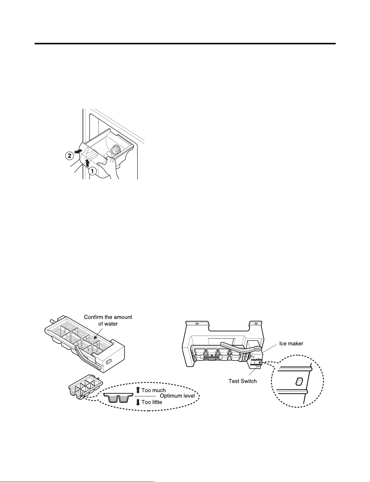
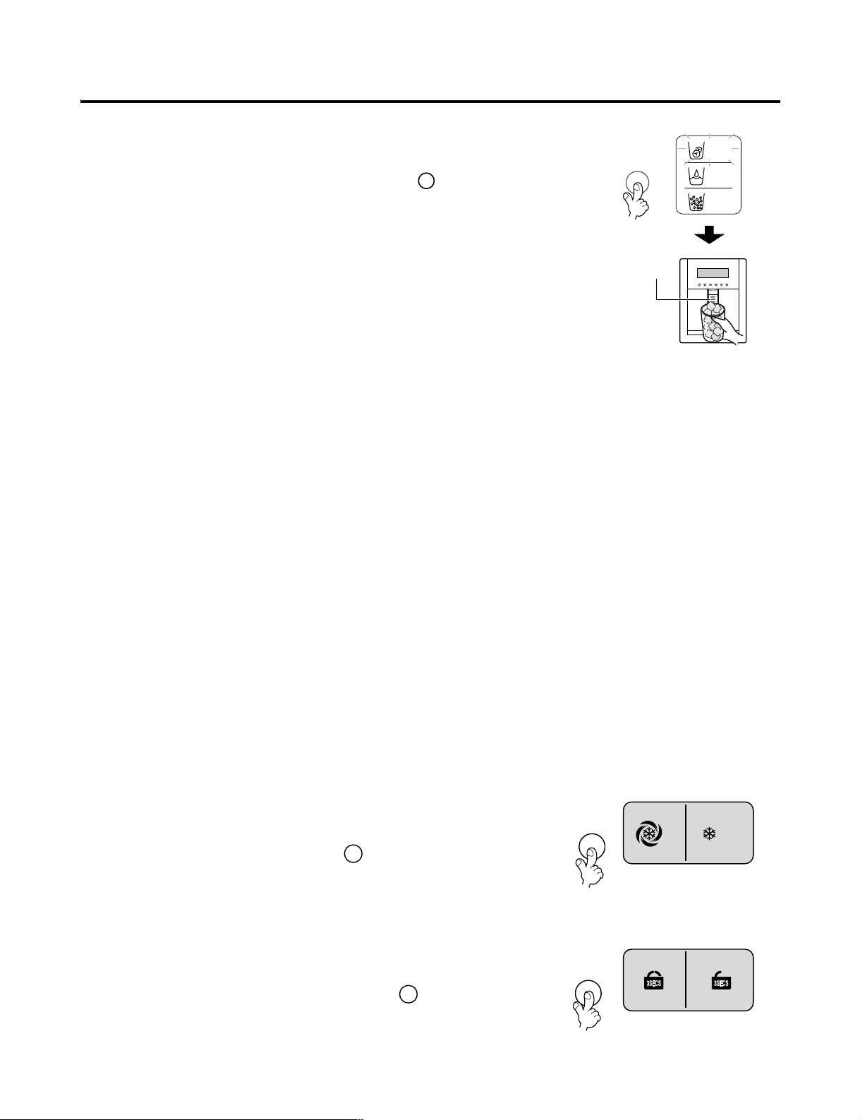
HOW TO INSTALL REFRIGERATOR
Test Switch
Confirm the amount
of water
Ice maker
Too much
Too little
Optimum level
3. How to Control the Amount of Water Supplied to Icemaker.
3-1. Confirm the amount of water supplied to the icemaker.
1. Pull out the ice bank in the upper part of the freezer compartment.
Caution : • Do not put hands or tools into the chute to confirm
the operation of geared motor.
it may damage refrigerator or hurt hands.)
• Check the operation of motor with its operation
noise.
2. Apply electricity after connecting water pipe.
1) Press test switch under the icemaker for two seconds as shown below.
2) The bell rings(ding~dong) and ice tray rotates and water comes out from the icemaker water tube.
3) The water shall be supplied two or three times into the tray. The amount of water supplied for each time is small.
Put a water container under the ice tray and press test switch.
4) When ice tray rotates, the water in it will spill. Collect the spilt water and throw away into the sink.
5) When ice tray has finished rotation, water comes out from the water tube. Confirm the amounts of water in the ice tray.
(refer to fig. The optimum amount of water is 110cc)
* It is acceptable if the adjusted level of water is a bit smaller than optimum level.
- 23 -
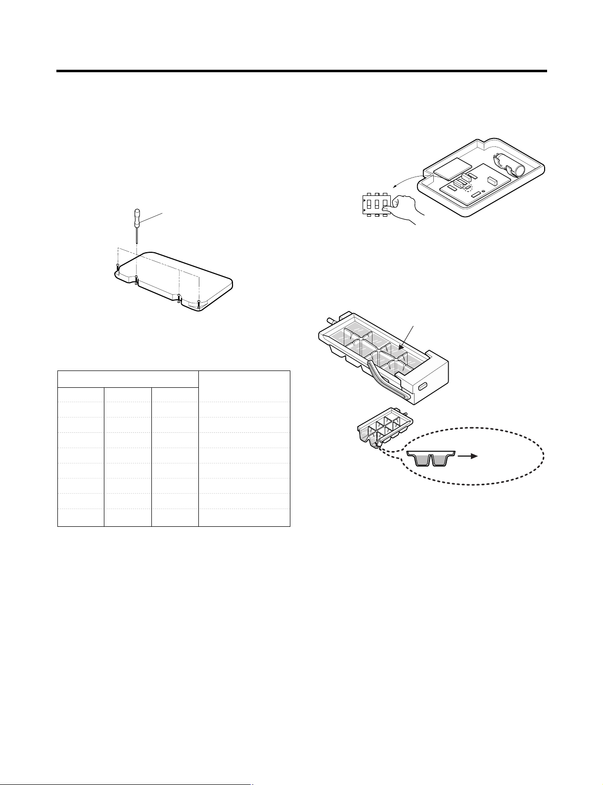
HOW TO INSTALL REFRIGERATOR
3-2. Control the amount of water supplied to the
icemaker.
Caution : • Please unplug the power cord from the wall
outlet and wait for more than three minutes
before disconnecting PWB cover as 310V is
applied in the control panel.
1. Disconnect PWB cover from the upper part of the
refrigerator.
(+) Driver
2. Adjust the amount of water supplied by using DIP
switch.
■ Water Supplying Time Control Option
SWITCH NO Water Suppling
S/W1 S/W2 S/W3 Time
OFF OFF OFF 6.5 Sec.
ON OFF OFF 5.5 Sec.
OFF ON OFF 6 Sec.
ON ON OFF 7 Sec.
OFF OFF ON 7.5 Sec.
ON OFF ON 8 Sec.
OFF ON ON 9 Sec.
ON ON ON 10 Sec.
Caution : When adjusting the amount of water supplied,
adjust step by step. Otherwise the water may
spill over.
Switch ON
Switch OFF
ON
1
23
3. When adjustment of control switch for the amount of
water supplied is complete, check the level of water in
the ice tray.
Confirm the amount
of water
Optimum level
1) The water supplying time is set at five seconds when the
refrigerator is delivered.
2) The amount of water supplied depends on the setting
time and water pressure (city water pressure).
3) If ice cube is too small, increase the water supplying
time. This happens when too small water is supplied into
the ice tray.
4) If ice cube sticks together, decrease the water supplying
time. This happens when too much water is supplied
into the ice tray.
- 24 -
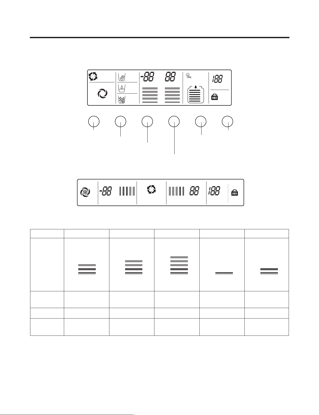
MICOM FUNCTION
Express Freezer
Dispenser selection button
Temperature adjustment button
for freezer compartment
Lock button
Filter reset button
Temperature adjustment button
for refrigerator compartment
EXPRESS FRZ DISPENSER FREEZER REFRIGERATOR FILTER RESET LOCK
ROOM TEMP
°
F
°
C
JET FRZ
EXPRESS FRZ
OFF
ICEBEAM
DOOR COOLING
CUBE
WATER
FRZ TEMP REF TEMP
CRUSH
°F
°C
°F
°C
5
4
3
2
1
FILTER STATUS
6
5
4
3
2
1
FILTER RESET
HOLD 3 SECS
UNLOCK
LOCK
ON
OFF
FRZ TEMP REF TEMP ROOM TEMP
°
F
°
C
°
F
°
C
°
F
°
C
ICEBEAM DOOR COOLING
1 2 3 4 5
UNLOCK
LOCK
5 4 3 2 1
1. Monitor Panel
1-1. GR-P257, GR-P217, GR-L257, GR-L217
1-2. GR-C257, GR-C217, GR-B257, GR-B217
2. Description of Function
2-1-1. Funnction of Temperature Selection
Division Power Initially On 1st Press 2st Press 3th Press 4th Press
5
Setting
temperature
Temperature
Control
Freezer Control
Refrigeration
Control
* The temperature can vary ±3 °C depending on the load condition.
❉ Whenever pressing button, setting is repeated in the order of (Medium) ➝ (Medium Max) ➝ (Max) ➝ (Min) ➝
4
3
2
1
Medium Medium Max Max Min Medium Min
-19 °C -22 °C -23 °C -15 °C -17 °C
3 °C2 °C0°C6 °C4 °C
(Medium Min).
• The actual inner temperature varies depending on the food status, as the indicated setting temperature is a target
temperature, not actual temperature within refrigerator.
• Refrigeration function is weak in the initial time. Please adjust temperature as above after using refrigerator for minimum
2~3 days.
5
4
3
2
1
- 25 -
5
4
3
2
1
5
4
3
2
1
5
4
3
2
1
MICOM FUNCTION
FILTER RESET
HOLD 3 SECS
2-1-2. LCD Back Light Control
1. In order to easily view display status on the LCD, LCD Back Light is turned on for a minute in application of initial power,
for a minute in button manipulation and for a minute after closing time from opening time of door.
2. If pressing any display button once with the backlight turned off, buzzer rings and button function is not performed but
only backlight is turned on (If pressing the first button with the back light turned off, only back light ON function is
performed).
3. If pressing the special freezing button and the freezing temperature adjustment button for more than a second, the back
light is turned on and all the graphics of LCD are turned on. If releasing the button, the LCD graphic is displayed in the
previous status and the back light is turned off (check LCD graphic and back light ON/OFF status).
2-1-3. Outside temperature display function
1. Outside temperature sensor at the left U of refrigerator senses ambient temperature and displays the outside temperature
in the left side of “Outside temperature” text on the LCD of the display part.
2. Ambient temperature is displayed up to -9°C ~ 49°C and displayed as “Lo” for less than -10°C and as “HI” for more than
50°C. If the ambient temperature sensor fails, it is displayed as “Er”.
3. Since display temperature of outside temperature is temperature sensed by the ambient sensor in the hinge U of the
freezing room, it may differ from the outside temperature display of other household electrical appliances.
2-1-4. Lock function (display button lock)
1. In power application of refrigerator, the only “Release” text is turned on at the right side of lock graphic of LCD with the
lock release status.
2. If desiring to lock the display status and pressing the lock/release button once, “Release” text is turned off at the right side
of lock graphic of LCD and “Lock” text is turned on with lock status.
3. The buzzer sound and function is not performed even if pressing display button other than lock/release key in the lock
status.
4. If desiring to release the lock status and pressing the lock/release button once, “Lock” text is turned off at the right side of
lock graphic of LCD and “Release” text is turned on with lock release status.
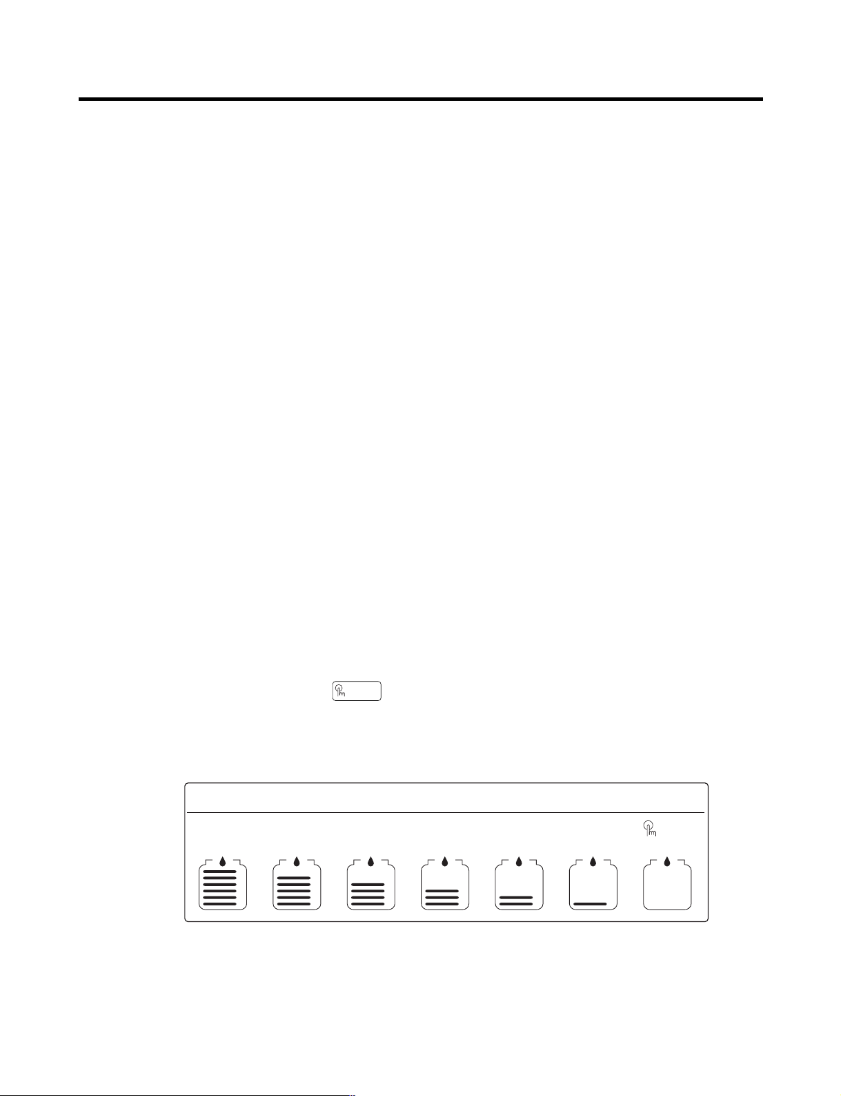
2-1-5. Filter condition display function
1. As demonstrated below, it displays the months left in units of 30 days until the filter replacement is required, starting from
when the refrigerator power usage is authorized.
2. After 6 months, the following sentence and will appear on the filter condition part of the LCD. "Press for 3
seconds after replacing filter"
3. After 6 months have passed, and if the filter has been replaced or you want to reset the filter condition display, press the
filter replacement button for more than 3 seconds and it will reset to the initial Power On state.
Classification
Filter Status
Display
In initial
Power On
FILTER STATUS
6
5
4
3
2
1
Pass of
a month
FILTER STATUS FILTER STATUS FILTER STATUS FILTER STATUS FILTER STATUS FILTER STATUS
6
5
4
3
2
1
Pass of
2 months
Pass of
3 months
6
5
4
3
2
1
6
5
4
3
2
1
Pass of
4 months
Pass of
5 months
6
5
4
3
2
1
6
5
4
3
2
1
Pass of
6 months
FILTER RESET
HOLD 3 SECS
6
5
4
3
2
1
- 26 -
2-2. Dispenser use selection
You can select water or ice.
❉ Please select water, slice ice and square ice by pressing button as you desire.
❉ Please press the push button lightly by catching and pushing in cup.
• The border line is indicated for the selected function.
• “Tak!” sounds if 5 seconds pass after ice comes out.
It is sound that the outlet of ice is closed.
REFERENCE : Please wait for 2-3 seconds in order to take final ice slices or drops of
water when taking out cup from the pressing switches after taking ice
or water.
2-3. Automatic ice maker
• The automatic ice maker can automatically make 8 pieces of ice cube at a time, 80 pieces a day. But these quantities may
be varied according to various conditions including how many times the refrigerator door opens and closes.
• Ice making stops when the ice storage bin is full.
• If you don’t want to use automatic ice-maker, change the ice-maker switch to ON-OFF.
If you want to use automatic ice-maker again, change the switch to OFF-ON.
NOTE : It is normal that a noise is produced when ice made is dropped into the ice storage bin.
2-4. When ice maker does not operate smoothly
Ice is lumped together
• When ice is lumped together, take the ice lumps out of the ice storage bin, break them into small pieces, and then place
them into the ice storage bin again.
• When the ice maker produces too small or lumped together ice, the amount of water supplied to the ice maker need to
adjusted. Contact the service center.
✻ If ice is not used frequently, it may lump together.
Power failure
• Ice may drop into the freezer compartment. Take the ice storage bin out and discard all the ice then dry it and place it
back. After the machine is powered again, crushed ice will be automatically selected.
The unit is newly installed
• It takes about 12 hours for a newly installed refrigerator to make ice in the freezer compartment.
2-5. Express Freezer
Please select this function for prompt freezer.
• “On” or “Off” is repeated whenever pressing button.
• The arrow mark graphic remains at the On status after flickering 4 times when
selecting Special Refrigeration “On”.
• Super freezer function automatically turns off if a fixed time passes.
2-6. Lock
This button stops operation of different button.
• Locking or Release is repeated whenever pressing the .
• Pressing the other button when selecting ‘LOCK’, the button does not operate.
MICOM FUNCTION
- 27 -
Ex) In selecting
"On"
Ex) In selecting
"Off"
Ex) In selecting
"LOCK"
Ex) In selecting
"LOCK" again
EXPRESS FRZ
LOCK
ON
OFF
LOCK
UNLOCK
DISPENSER
Pressing
Switch
CUBE
WATER
CRUSH
DISPENSER
EXPRESS FRZ
LOCK
MICOM FUNCTION
2-7. Super freezing
1. Super freezing is function to improve cooling speed of the freezing room by consecutively operating compressors and
freezing room fan. If pressing the super freezing button, “Turn Off” text of the LCD panel is turned off and “Turn On” is
immediately turned on and “Arrow ( )” graphic is turned on after flickering once.
2. super freezing is cycled in order of Selection/ Release (“Turn On” / “Turn Off”) whenever pressing the selection button.
3. super freezing is released if power failure occurs and then returns to the original status.
4. Temperature setting is not changed even if selecting the super freezing.
5. The change of temperature setting at the freezing room or the cold storage room is allowed with super freezing selected
and processed.
6. The cold storage room operates the status currently set with super freezing selected and processed.
7. If selecting the super freezing, the super freezing function is released after continuously operating compressor and
freezing room fan.
8. If frost removal starting time is arrived during super freezing, super freezing operation is done only for the remaining time
after completion of frost removal when the super freezing operation time passes 90 minutes. If passing 90 minutes, super
freezing operation is done only for 2 hours after completion of frost removal.
9. If pressing super freezing button during frost removal, the super freezing LCD is turned on but if pressing the super
freezing, compressor operates after the remaining time has passed.
10. If selecting super freezing within 7 minutes (delay for 7 minutes of compressor) after the compressor stops, compressor
operates after the remaining time has passed.
11. The freezing room fan motor operates at the high speed of RPM during operation of super freezing.
2-8. *Miracle Zone function
1. Miracle Zone is located at the bottom room of R-room and maintains optimum temperature depending on foods through
selection of desired foods kept in the Miracle Zone from vegetables to meat with a display.
Set temperature in the Miracle Zone by using a separate selection button at the right side of the Miracle Zone. Initial
notch is in “veg.”status in application of power. Whenever pressing buttons, notch changes while LED is displayed in the
order of “veg. → cheeze → meat → veg.”.
Provided that selected notch LED turns off if opening doors of the R-room and it turns off if closing doors of R-room.
2. Temperature of the miracle zone is controlled with a stemping damper at the left side of the miracle zone and controlled
with a miracle zone at the rear side of miracle zone.
3. Change of the notch by temperature control S/W at the miracle zone is controlled after 10 seconds have passed after
selecting final notches.
4. Miracle zone damper is forcedly closed during test mode or defrost mode.
Miracle Zone NOTCH meat cheeze veg.
Setting Indication -1°C2°C4°C
2-9. Control of variable type of freezing room fan
1. To increase cooling speed and load response speed, MICOM variably controls freezing room fan motor at the high speed
of RPM and standard RPM.
2. MICOM only operates in the input of initial power or super freezing operation or load response operation for the high
speed of RPM and operates in the standard RPM in other general operation.
3. If opening doors of freezing / cold storage room or home bar while fan motor in the freezing room operates, the freezing
room fan motor normally operates (If being operated in the high speed of RPM, it converts operation to the standard
RPM). However, if opening doors of freezing room or home bar, the freezing room fan motor stops.
4. As for monitoring of BLDC fan motor error in the freezing room, MICOM immediately stops the fan motor by determining
that the BLDC fan motor is locked or poor if there would be position signal for more than 115 seconds at the BLDC motor.
Then it displays failure (refer to failure diagnosis function table) at the display part of refrigerator, the BLDC motor doesn’t
operate more. If you want to operate the BLDC motor, turn off and on power resource.
- 28 -
Doors of freezing /
cold storage room
or home bar
BUZZER
Closing
Opening
Within
a minute
A minute
30
seconds30seconds30seconds
Opening
Closing Closing
3 Times 3 Times 3 Times 3 Times
MICOM FUNCTION
2-10. Control of M/C room fan motor
1. The M/C room fan motor performs ON/OFF control by linking with the COMP.
2. It controls at the single RPM without varying RPM.
3. Failure sensing method is same as in fan motor of freezing fan motor (refer to failure diagnosis function table for failure
display).
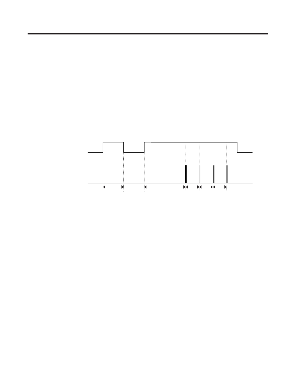
2-11. Door opening alarm
1. Buzzer generates alarm sound if doors are not closed even when more than a minute consecutively has passed with
doors of freezing / cold storage room or home bar opened.
2. Buzzer rings three times in the interval of 0.5 second after the first one-minute has passed after doors are opened and
then repeats three times of On/Off alarm in the cycle of every 30 seconds.
3. If all the doors of freezing / cold storage room or home bar are closed during door open alarm, alarm is immediately
released.
2-12. Ringing of button selection buzzer
1. If pressing the front display button, “Ding ~ “ sound rings.
2-13. Ringing of compulsory operation, compulsory frost removal buzzer
1. If pressing the test button in the main PCB, “Phi ~ “ sound rings.
2. In selecting compulsory operation, alarm sound is repeated and completed in the cycle of On for 0.2 second and Off for
1.8 second three times.
3. In selecting compulsory frost removal, alarm sound is repeated and completed in the cycle of On for 0.2 second , Off for
0.2 second, On for 0.2 second and Off for 1.4 second three times.
2-14. Frost removal function
1. Frost removal is performed whenever total operation time of compressor becomes 7 ~ 7.5 hour.
2. In providing initial power (or returning power failure), frost removal starts whenever total operation time of compressor
becomes 4 ~ 4.5 hour.
3. Frost removal is completed if temperature of a frost removal sensor becomes more than 5°C after starting frost removal.
Poor frost removal is not displaced if it does not arrive at 5°C even if two hours have passed after starting frost removal.
4. No removal is done if frost removal sensor becomes poor (snapping or short-circuit).
- 29 -
MICOM FUNCTION
POWER
ON
COMP
ON
F-FAN
&
C-FAN
ON
R-STEP
MOTOR
DAMPER
ON
HOME
BAR
HEATER
ON
MIRACLE
ZONE
STEP
DAMPER
MOTOR
ON
FROST
REMOVAL
HEATER
OFF
HOME
BAR
HEATER
ON
HOME
BAR
HEATER
OFF
FROST
REMOVAL
HEATER
ON
DAMPER
&
DUCT DOOR
HEATER
ON
DAMPER
&
DUCT DOOR
HEATER
OFF
0.3
sec.
0.3
sec.
0.3
sec.
0.3
sec.
0.3
sec.
0.3
sec.
0.3
sec.
POWER
ON
PIPE
&
DISP'
HEATER
ON
0.3
sec.
PIPE
&
DISP'
HEATER
OFF
0.3
sec.
COMP
ON
0.3
sec.
F-FAN
&
C-FAN
ON
0.3
sec.
R-STEP
MOTOR
DAMPER
ON
0.3
sec.
MIRACLE
ZONE
STEP
DAMPER
MOTOR
ON
0.3
sec.
HOME
BAR
HEATER
ON
TEST
S/W
(PRESS
Once)
OTHER
LOAD
OFF
COMP
ON
F-FAN
&
C-FAN
ON
R-STEP
MOTOR
DAMPER
ON
MIRACLE
ZONE
STEP
DAMPER
MOTOR
CLOSE
TEST
S/W
(PRESS
2 Times)
COMP
OFF
F-FAN
&
C-FAN
OFF
FROST
REMOVAL
HEATER
ON
R-STEP
MOTOR
DAMPER
CLOSE
0.3
sec.
0.3
sec.
0.3
sec.
0.3
sec.
0.3
sec.
0.3
sec.
0.3
sec.
0.3
sec.
0.3
sec.
0.3
sec.
0.3
sec.
0.3
sec.
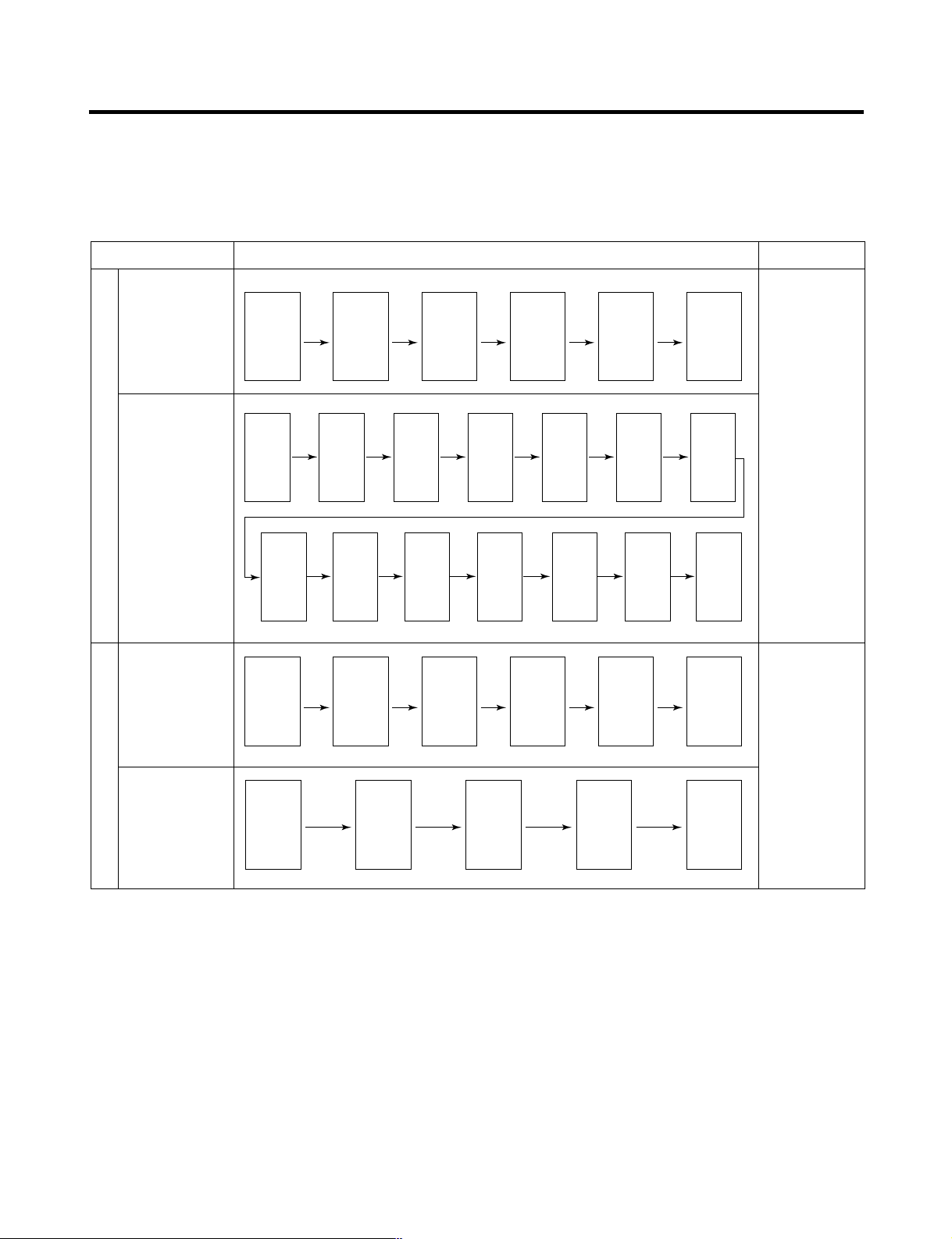
2-15. Sequential operation of built-in product
Built-in products such as compressor, frost removal heater, freezing room fan, Cooling Fan and step motor damper are
sequentially operated as follows for preventing noise and part damage occurred due to simultaneous operation of a lot of
parts in applying initial power and completing test.
Function Load Operation Sequence Remark
When temperature
of a frost removal
sensor becomes
more than 45°C
(In purchase,
movement)
In applying Initial power TEST MODE
When
temperature of a
frost removal
sensor becomes
less than 45°C
(In power failure,
service)
Test mode 1
(Compulsory
function)
Test mode 2
(Compulsory frost
removal)
If error occurs
during operation,
initial operation is
not done.
■
Sequence of
load operation
when closing
F-room and
R-room.
If pressing switch
once more in the
test mode 2 or
temperature of a
frost removal
sensor is more
than 5°C, it
immediately
returns to the test
mode for initial
operation
(COMP operates
after 7 minutes).
- 30 -
 Loading...