

Page 1

System
Heat Pump Indoor Unit
INSTALLATION MANUAL
LG
MODELS : SE/S3 Series
Type : ART COOL Mirror
IMPORTANT
• Please read this installation manual completely
before installing the product.
• Installation work must be performed in accordance
with the national wiring standards by authorized
personnel only.
• Please retain this installation manual for future
reference after reading it thoroughly.
ENGLISH ITALIANO ESPAÑOL FRANÇAIS DEUTSCH
Page 2
2 Indoor Unit
Artcool Deluxe Type Indoor Unit Installation Manual
TABLE OF CONTENTS
❏ Installation guide map
❏Four type "A" screws & plastic
anchors
❏Connecting cable
❏Pipes: Gas side
Liquid side
(Refer to Product Data)
❏Insulation materials
❏Additional drain pipe
❏Two type "B" screws
❏Level gauge
❏Screw driver
❏Electric drill
❏Hole core drill
❏Horizontal meter
❏Flaring tool set
❏Specified torque wrenches
(different depending on model No.)
❏Spanner.......Half union
❏A glass of water
❏Screw driver
❏Hexagonal wrench
❏Gas-leak detector
❏Vacuum pump
❏Gauge manifold
❏Owner's manual
❏Thermometer
❏Holder Remote Controller
Installation Parts ....................3
Safety Precautions.................4
Installation
Selection of the best location
................................................7
Piping Method........................8
Drain Piping .........................12
Wiring Connection...............13
Installation of Remote
Controller..............................14
Installation Requirements
Required Parts Required Tools
Page 3

Installation Manual 3
Installation Parts
ENGLISH
Installation Plate
Installation Plate
Type "A" screws and plastic anchorsType "A" screws and plastic anchors
Installation plate
Type 1
Type 1 Type 2
Type 2
Installation Parts
Page 4
4 Indoor Unit
Safety Precautions
Safety Precautions
To prevent injury to the user or other people and property damage, the following instructions must be followed.
■ Be sure to read before installing the air conditioner.
■ Be sure to observe the cautions specified here as they include important items related to safety.
■ Incorrect operation due to ignoring instruction will cause harm or damage. The seriousness is classified by the
following indications.
■ Meanings of symbols used in this manual are as shown below.
This symbol indicates the possibility of death or serious injury.
This symbol indicates the possibility of injury or damage to properties only.
Be sure not to do.
Be sure to follow the instruction.
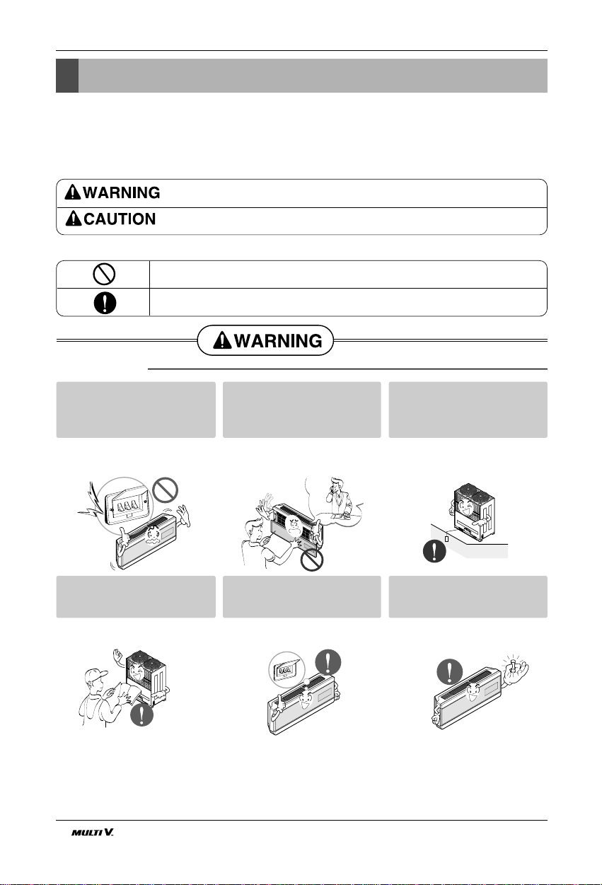
■ Installation
Do not use a defective or underrated circuit breaker. Use this
appliance on a dedicated circuit.
• There is risk of fire or electric shock.
For electrical work, contact the
dealer, seller, a qualified electrician, or an Authorized Service
Center.
• Do not disassemble or repair the
product. There is risk of fire or electric shock.
Always ground the product.
• There is risk of fire or electric shock.
Install the panel and the cover
of control box securely.
• There is risk of fire or electric shock.
Always install a dedicated circuit and breaker.
• Improper wiring or installation may
cause fire or electric shock
Use the correctly rated breaker
or fuse.
• There is risk of fire or electric shock.
Page 5
Installation Manual 5
Safety Precautions
ENGLISH
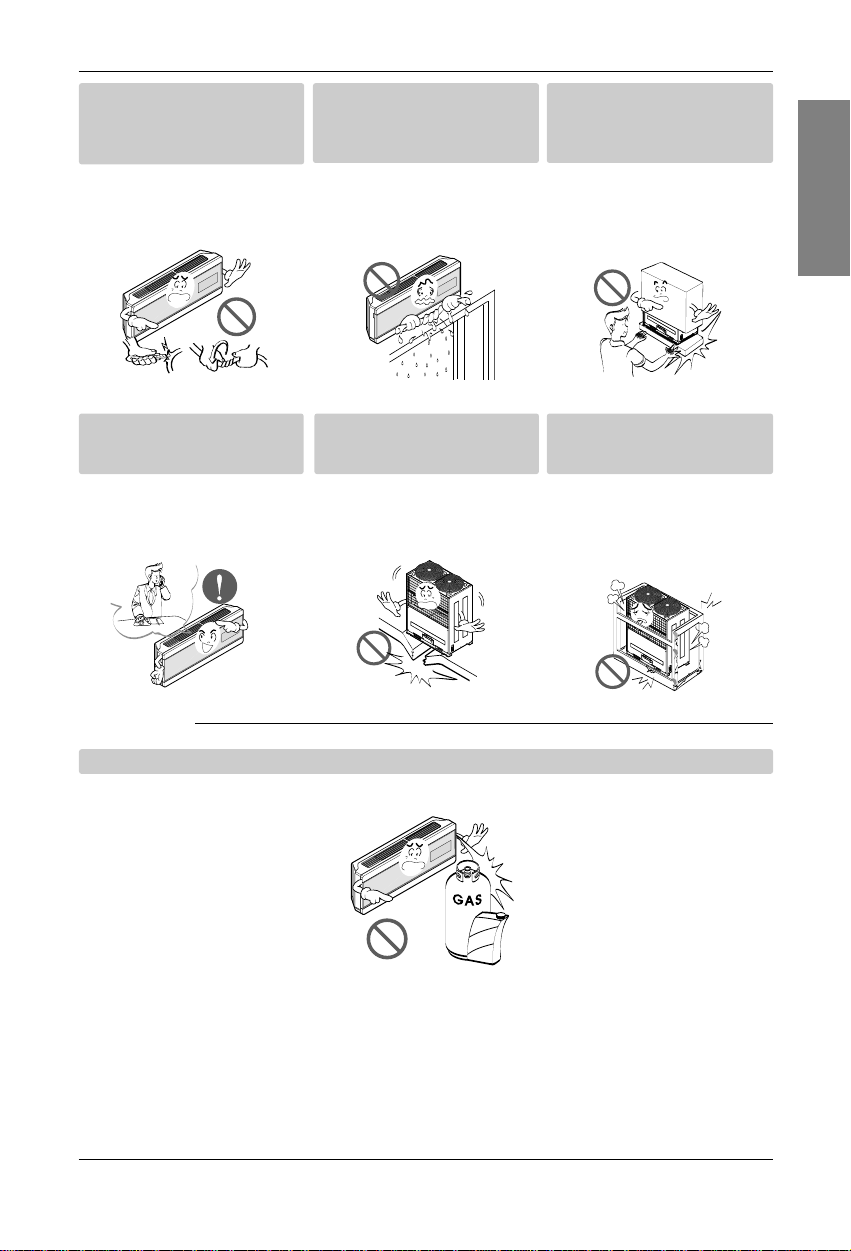
■ Operation
Do not modify or extend the
power cable.
• There is risk of fire or electric shock.
Do not let the air conditioner
run for a long time when the
humidity is very high and a door
or a window is left open.
• Moisture may condense and wet or
damage furniture.
Be cautious when unpacking
and installing the product.
• Sharp edges could cause injury. Be
especially careful of the case edges
and the fins on the condenser and
evaporator.
For installation, always contact
the dealer or an Authorized
Service Center.
• There is risk of fire, electric shock,
explosion, or injury.
Do not install the product on a
defective installation stand.
• It may cause injury, accident, or
damage to the product.
Be sure the installation area
does not deteriorate with age.
• If the base collapses, the air conditioner could fall with it, causing property damage, product failure, and
personal injury.
Do not store or use flammable gas or combustibles near the product.
• There is risk of fire or failure of product.
Gasolin
Page 6
6 Indoor Unit
Safety Precautions
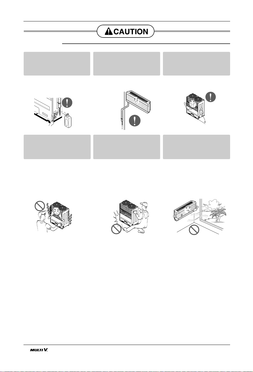
Always check for gas (refrigerant) leakage after installation or
repair of product.
• Low refrigerant levels may cause
failure of product.
Install the drain hose to ensure
that water is drained away properly.
• A bad connection may cause water
leakage.
Keep level even when installing
the product.
• To avoid vibration or water leakage.
Do not install the product where
the noise or hot air from the outdoor unit could damage the
neighborhoods.
• It may cause a problem for your
neighbors.
Use two or more people to lift
and transport the product.
• Avoid personal injury.
Do not install the product where
it will be exposed to sea wind
(salt spray) directly.
• It may cause corrosion on the product.
Corrosion, particularly on the condenser and evaporator fins, could
cause product malfunction or inefficient
operation.
■ Installation
90˚
Page 7

Installation Manual 7
Installation
ENGLISH
Read completely, then follow step by step.
Installation
Selection of the best location
CAUTION : In case that the unit is installed near the sea, the installation parts
may be corroded by salt. The installation parts (and the unit) should be taken
appropriate anti-corrosion measures.
• There should not be any heat source or steam
near the unit.
• There should not be any obstacles to prevent the
air circulation.
• A place where air circulation in the room will be
good.
• A place where drainage can be easily obtained.
• A place where noise prevention is taken into consideration.
• Do not install the unit near the door way.
• Ensure the spaces indicated by arrows from the
wall, ceiling, fence, or other obstacles.
The mounting wall should be strong and solid
enough to protect it from the vibration.
Mount the installation plate on the wall with four
Type "A" screws.
(If mounting the unit on the concrete wall, consider using anchor bolts.)
• Always mount the Installation plate horizontally
by aligning the marking-off line by means of the
thread and a level.
More than 10 cm
More than 50 cm
More than 2.3m
More than 50 cm
Chassis
Hook
Installation Plate
Type “A”
Type 2
(SE chassis)
Type 1
(S3 chassis)
Installation Plate
The lower left and the right side of Installation Plate
(S3 chassis)
Type 1
155mm
Ø70mm
306mm
Left rear piping Right rear piping
Installation plate
78mm
155mm
Ø70mm
Type 2
(SE chassis)
110mm
Ø70mm
85mm
Left rear piping Right rear piping
Installation plate
65mm
110mm
Ø70mm
Page 8

8 Indoor Unit
Installation
Piping Method
■ Preparing the indoor unit's piping and drain hose for
installation through the wall.
■ Remove the plastic tubing retainer(see illustration
below) and pull the tubing and drain hose away from
chassis.
■ Replace the plastic tubing holder in the original position.
1. Route the indoor tubing and the drain hose in the
direction of rear left.
2. Insert the connecting cable into the indoor unit
from the outdoor unit through the piping hole.
■ Do not connect the cable to the indoor unit.
■ Make a small loop with the cable for easy connection
later.
3. Tape the tubing, drain hose and the connecting
cable. Be sure that the drain hose is located at the
lowest side of the bundle. Locating at the upper
side can cause drain pan to overflow inside the
unit.
: If the drain hose is routed inside the room,
insulate the hose with an insulation material* so that dripping from "sweating"(condensation) will not damage furniture or floors.
*Foamed polyethylene or equivalent is recommended.
4. Indoor unit installation
■ Hook the indoor unit onto the upper portion of the
installation plate.(Engage the two hooks of the rear
top of the indoor unit with the upper edge of the
installation plate.) Ensure that the hooks are properly
seated on the installation plate by moving it left and
right.
Press the lower left and right sides of the unit against
the installation plate until the hooks engage into their
slots(clicking sound).
NOTICE
For right rear piping
• Drill the piping hole with a ø70mm hole core drill.
Drill the piping hole at either the right or the left
with the hole slightly slanted to the outdoor side.
Drill a Hole in the Wall
5-7mm
(3/16"~5/16")
Indoor
WALL
Outdoor
Tape
Connecting
pipe
Drain hose
Connecting cable
Drain hose
Connecting
cable
Drain hose
Page 9

Installation Manual 9
Installation
ENGLISH
5. Connecting the pipings to the indoor unit and drain
hose to drain pipe.
■ Align the center of the pipings and sufficiently tighten
the flare nut by hand.
■ Tighten the flare nut with a wrench.
■ Mount the clamp on the boss with a type "B"
screw.(optional)
■ When extending the drain hose at the indoor
unit, install the drain pipe.
6. Wrap the insulation material around the connecting portion.
■ Overlap the connection pipe insulation material
and the indoor unit pipe insulation material. Bind
them together with vinyl tape so that there is no
gap.
■ Wrap the area which accommodates the rear piping housing section with vinyl tape.
■ Bundle the piping and drain hose together by
wrapping them with vinyl tape over the range with-
in which they fit into the rear piping housing section.
1. Route the indoor tubing and the drain hose to the
required piping hole position.
2. Insert the piping, drain hose and the connecting
cable into the piping hole.
For left rear piping
GAS LIQUID
Ø12.7[5.5kg.m] Ø6.35[1.8kg.m]
Ø15.88[6.6kg.m] Ø9.52[4.2kg.m]
Pipe Size[Torque]
Indoor unit tubing
Flare nut Pipings
Spanner (fixed)
Flare nut
Torque
wrench
Indoor
unit tubing
Connection
pipe
Connection
pipe
Vinyl tape
(wide)
Connecting cable
Wrap with vinyl tape
Vinyl tape(narrow)
Pipe
Drain hose
Wrap with vinyl tape
Vinyl tape(wide)
Indoor
unit pipe
Pipe
Type "B" screw
Clamp
Boss
Drain hose
Drain pipe
Indoor unit
drain hose
Adhesive
Vinyl tape(narrow)
Plastic bands
Insulation material
Connecting cable
Drain pipe
Page 10

10 Indoor Unit
Installation
3. Insert the connecting cable into the indoor unit.
■ Don't connect the cable to the indoor unit.
■ Make a small loop with the cable for easy connec-
tion later.
4. Tape the drain hose and the connecting cable.
• Connecting cable
5. Indoor unit installation
■ Hang the indoor unit from the hooks at the top of
the installation plate.
■ Insert the spacer etc. between the indoor unit and
the installation plate and separate the bottom of
the indoor unit from the wall.
6. Connecting the pipings to the indoor unit and
the drain hose to drain pipe.
■ Align the center of the pipings and sufficiently
tighten the flare nut by hand.
■ Tighten the flare nut with a wrench.
■ When extending the drain hose at the indoor unit,
install the drain pipe.
7. Wrap the insulation material around the connecting portion.
■ Overlap the connection pipe heat insulation and
the indoor unit pipe heat insulation material. Bind
them together with vinyl tape so that there is no
gap.
■ Wrap the area which accommodates the rear pip-
ing housing section with vinyl tape.
Vinyl tape
Adhesive
Drain hose
Indoor unit drain hose
(narrow)
Plastic bands
Insulation material
Vinyl tape
(narrow)
Connection
pipe
Connecting
cable
Indoor
unit piping
Pipe
Vinyl tape
(wide)
Wrap with vinyl tape
Indoor unit tubing
Flare nut Pipings
Torque
wrench
Indoor
unit tubing
Spanner (fixed)
Connection
pipe
Flare nut
Installation plate
Spacer
Indoor unit
8cm
GAS LIQUID
Ø12.7[5.5kg.m] Ø6.35[1.8kg.m]
Ø15.88[6.6kg.m] Ø9.52[4.2kg.m]
Pipe Size[Torque]
Page 11

Installation Manual 11
Installation
ENGLISH
■ Bundle the piping and drain hose together by
wrapping them with cloth tape over the range
within which they fit into the rear piping housing
section.
8. Reroute the pipings and the drain hose across
the back of the chassis.
9. Set the pipings and the drain hose to the back of
the chassis with the tubing holder.
■ Hook the edge of tubing holder to tap on chassis
and push the bottom of tubing holder to be
engaged at the bottom of chassis.
10. Indoor unit installation
■ Remove the spacer.
■ Ensure that the hooks are properly seated on the
installation plate by moving it left and right.
Press the lower left and right sides of the unit
against the installation plate until the hooks engage
into their slots(clicking sound).
Drain hose
Vinyl tape
(narrow)
Pipe
Wrap with
vinyl tape(wide)
Piping for
passage through
piping hole
Tubing holder
Drain hose
Connecting
cable
Installation Information (For left piping)
• Good case
For left piping. Follow the instruction below.
■
Press on the upper side of clamp. ( )
■
Unfold the tubing to downward slowly. ( )
CAUTION
Page 12

12 Indoor Unit
Installation
Drain Piping
1. To remove the front panel from the indoor unit,
remove the front panel from the indoor unit
cabinet.
■ Set the air direction louvers up-and-down to the
position(horizontally) by hand.
■ Remove the securing screws that retain the front
panel. Pull the lower left and right sides of the grille
toward you and lift it off.
2. To check the drainage.
■ Pour a glass of water on the evaporator.
■ Ensure the water flows through the drain hose of
the indoor unit without any leakage and goes out
the drain exit.
■
The drain hose should point downward for easy drain
flow.
• Bad case
■
Following bending type from right to left could cause
problem of pipe damage.
CAUTION
Air
filter
Inlet Grille
Front panel
Type 1
Type 2
Connecting area
drain hose
Leakage
checking
Type 1
Type 2
Downward slope
Do not raise
Accumulated
drain water
Tip of drain hose
dipped in water
Air
Waving
Water
leakage
Water
leakage
Ditch
Less than
50mm gap
Water
leakage
■ Do not make drain piping.
Page 13

ENGLISH
Installation Manual 13
Installation
CAUTION:
After the confirmation of the above conditions, prepare the wiring as follows:
1) Never fail to have an individual power circuit specifically for the air conditioner. As for the
method of wiring, be guided by the circuit diagram posted on the inside of control cover.
2) The screw which fasten the wiring in the casing of electrical fittings are liable to come loose from
vibrations to which the unit is subjected during the course of transportation. Check them and
make sure that they are all tightly fastened. (If they are loose, it could cause burn-out of the
wires.)
3) Specification of power source.
4) Confirm that electrical capacity is sufficient.
5) See to that the starting voltage is maintained at more than 90 percent of the rated voltage marked
on the name plate.
6) Confirm that the cable thickness is as specified in the power source specification.
(Particularly note the relation between cable length and thickness.)
7) In a wet or moist area, always install an earth leakage circuit breaker.
8) The following would be caused by voltage drop.
• Vibration of a magnetic switch, which will damage the contact point, fuse breaking, disturbance of the
normal function of the overload.
9) The means for disconnection from a power supply shall be incorporated in the fixed wiring and
have an air gap contact separation of at least 3mm in each active(phase) conductors.
Wiring Connection
Connect the wires to the terminals on the control
board individually according to the outdoor unit
connection.
• Ensure that the color of the wires of outdoor unit
and the terminal No. are the same as those of
indoor unit respectively.
Terminal Block Indoor
1(L) 2(N) 3 4
INDOOR POWER INPUT
Terminal Block Outdoor
ABC D Vcc
Connecting cable
Page 14

14 Indoor Unit
Installation
1. Remove the battery cover from the remote
controller.
• Slide the cover according to the arrow
direction.
2. Insert the two batteries.
• Be sure that the (+) and (-) directions are
correct.
• Be sure that both batteries are new.
3. Re-attach the cover.
• Slide it back into position.
HOW TO MOUNT ONTO A WALL
HOW TO INSERT BATTERIES
• Do not use rechargeable batteries,
such batteries differ from standard
dry cells in shape, dimensions, and
performance.
• Romove the batteries from the
remote controller if the air conditioner is not going to be used for some
long time.
Installation of Remote Controller
Page 15

Installation Manual 15
Installation
ENGLISH
Remote controller
box body
Cord clamp
(accessory)
Lever carefully
the box open
using a screw
driver, etc.
Front case
The lower part
Face of wall
Under plate
Screw (accessory)
• Separate the under plate from Remote
controller box.
• Attach insulator to under plate.
• Fix the under plate on the wall
•
Fix the cord clamps on the wall by ø 3 tapping screws (accessory).
•
Fix the remote controller cord.
WIRED REMOTE CONTROLLER INSTALLATION
DISASSEMBLING
ELECTRICAL WIRING
Wire and make sure that teminal
numbers are matched on unit side and
remote controller side.
The maximum length of the cord is 100m.
If the length of the cord exceeds 50m,
use a wire size greater than 0.5mm
2
.
Remote controller
(Main board)
CN REMO
• Although the room temperature sensor is in the indoor unit, the remote controller should be installed in such
places away from direct sunlight and high humidity.
Installation of the remote controller
• Select places that are not splashed with water.
• Select controller position after receiving customer approval.
• The room temperature sensor is built in the indoor unit.
• This remote controller equipped with liquid crystal display. If this position is higher or lower, display is difficult
to see.(The standard height is 1.2 ~1.5m high)
Routing of the remote controller cord
• Keep the remote controller cord away from the refrigerant piping and the drain piping.
• To protect the remote controller cord from electrical noise, place the cord at least 5cm away from other
power cables. (audio equipment. television set, etc.)
• If the remote controller cord is secured to the wall, provide a trap at the top of the cord to prevent water
droplets from running.
Installation of Remote Control
Page 16

16 Indoor Unit
Installation
You can choose the RPM(or air volume) of indoor
motor according to the height of ceiling to supply the
comfortable atmosphere to consumers.
Procedure
1. Choose the selectable position in the table after
measuring the height of ceiling.
2. In the case of changing the height as "high" or "low",
open the rear cover of the wired remote-controller.
3. Move the slide switch to the set position.
4. Close the rear cover and check if it works nomally.
2) Adjusting air volume to the height of ceiling
TH
R14H
SW TH
REMO
MAIN
2TH
OP7
R18H
R17H
OP6
LO
STAND
SW HIGH
HI
R03S
C070
R04S
R02S
R01S
OP3
OP2 OP1
R19H
R11H
R13H R12H
OP5R16H OP4
R15H
CO1H
Lo
Hi
STAND
Slide switch for ceiling height
Slide switch for 2 Thermistor
Standard
(Default)
Low ceiling
High Ceiling
Ceiling height Mode of slide switch Change of air volume Remark
more than 4.0m High Ceiling Increasing
3.2~4.0m Standard -
less than 3.2m Low Ceiling Decreasing
Maunfactured in stan-
dard mode
1) Two Thermistor System
(1) Open the rear cover of the wired remote-controller to
set the mode.
(2) Select one of three selectable modes as follows.
• Position 1:
The room temperature is controlled by the thermistor
of the main body.
• Position 2:
The room themperature is controlled by the thermistor of the wired remote-controller, control the temperature according to the position of wired remote-controller.
• Position 3:
The room temperature is controlled by lower temperature between the temperature of main body and of
remote-controller sensor.
(3) Move the slide switch to set position.
(4) Close the rear cover and check if it works normally.
TH
R14H
SW TH
REMO
MAIN
2TH
OP7
R18H
R17H
OP6
LO
STAND
SW HIGH
HI
R03S
C070
R04S
R02S
R01S
OP3
OP2 OP1
R19H
R11H
R13H R12H
OP5R16H OP4
R15H
CO1H
REMO
Room T emp. sensor
2TH
MAIN
Position 2
Position 1
Position 3
Slide switch for ceiling height
Slide switch for 2 Thermistor
Optional operation
CAUTION :
• Select the position after counselling with a customer.
In case of cooling mode, room temperature is controlled by the main body sensor.
• To control the room temperature by a wired remote controller, install the remote
controller (room temp. sensor) to sense the temperature more accurately.
• Maunfactured in the position 3.
Page 17

P/No.: 3828A20873F
Printed in Korea
After reading this manual, keep it in a place easily accessible to the user for future reference.
 Loading...