

LG LRH7160D Series, LRH7080D Series Owner's Manual

1303 (V2.0)
Please read this manual carefully before operating your set and retain it for
future reference.
OWNER’S MANUAL
Hybrid Digital Video
Recorder
MODELS
LRH7160D Series
LRH7080D Series
2
Safety Information
1
Safety Information
1
Safety Information
CAUTION
RISK OF ELECTRIC SHOCK
DO NOT OPEN
CAUTION: TO REDUCE THE RISK OF ELECTRIC SHOCK
DO NOT REMOVE COVER (OR BACK)
NO USER-SERVICEABLE PARTS INSIDE
REFER SERVICING TO QUALIFIED SERVICE PERSONNEL.
This lightning flash with arrowhead symbol
within an equilateral triangle is intended
to alert the user to the presence of
uninsulated dangerous voltage within the
product’s enclosure that may be of sufficient
magnitude to constitute a risk of electric
shock to persons.
The exclamation point within an equilateral
triangle is intended to alert the user to
the presence of important operating and
maintenance (servicing) instructions in the
literature accompanying the product.
FCC WARNING: This equipment may generate or use radio
frequency energy. Changes or modifications to this equipment may
cause harmful interference unless the modifications are expressly
approved in the instruction manual. The user could lose the
authority to operate this equipment if an unauthorized change or
modification is made.
REGULATORY INFORMATION: FCC Part 15
This equipment has been tested and found to comply with the
limits for a Class A digital device, pursuant to Part 15 of the FCC
Rules. These limits are designed to provide reasonable protection
against harmful interference when the equipment is operated in a
commercial environment.
This equipment generates, uses, and can radiate radio frequency
energy and, if not installed and used in accordance with the
instruction manual, may cause harmful interference to radio
communications.
Operation of this equipment in a residential area is likely to cause
harmful interference in which case the user will be required to
correct the interference at his own expense.
• A suitable conduit entries, knock-outs or glands shall be
provided in the cable entries of this product in the end user.
• Caution: Danger of explosion if battery is incorrectly replaced.
Replaced only with the same or equivalent type recommended
by the manufacturer. Dispose of used batteries according to the
manufacturer’s instructions.
• Holes in metal, through which insulated wires pass, shall
have smooth well rounded surfaces or shall be provided with
brushings.
This Class A digital apparatus complies with Canadian ICES-003.
Cet appareil numérique de la classe A est conforme à la norme
NMB-003 du Canada.
Warning: Do not install this equipment in a confined space such as
a bookcase or similar unit.
Warning: Wiring methods shall be in accordance with the National
Electric Code, ANSI/NFPA 70.
Warning: This is a class A product. In a domestic environment this
product may cause radio interference in which case the user may
be required to take adequate measures.
Warning: To reduce a risk of fire or electric shock, do not expose
this product to rain or moisture.
Caution: This installation should be made by a qualified service
person and should conform to all local codes.
Caution: To avoid electrical shock, do not open the cabinet. Refer
servicing to qualified personnel only.
Caution: The apparatus should not be exposed to water (dripping
or splashing) and no objects filled with liquids, such as vases, should
be placed on the apparatus.
Caution:
This product employs a Laser System. To ensure proper use of this
product, please read this owner’s manual carefully and retain it
for future reference. Should the unit require maintenance, contact
an authorized service center. Use of controls, adjustments, or the
performance of procedures other than those specified herein may
result in hazardous radiation exposure. To prevent direct exposure
to laser beam, do not try to open the enclosure.
To disconnect power from mains, pull out the mains cord plug.
When installing the product, ensure that the plug is easily
accessible.
LG Electronics hereby declares that this/these
product(s) is/are in compliance with the essential
requirements and other relevant provisions of
Directive 2004/108/EC, 2006/95/EC, and 2011/65/
EU.
Contact oce for compliance of this product :
LG Electronics Inc.
EU Representative, Krijgsman 1,
1186 DM Amstelveen, The Netherlands
Safety Information
3
1
Safety Information
Disposal of your old appliance
1. When this crossed-out wheeled bin symbol is
attached to a product it means the product is
covered by the European Directive 2002/96/EC.
2. All electrical and electronic products should
be disposed of separately from the municipal
waste stream via designated collection facilities
appointed by the government or the local
authorities.
3. The correct disposal of your old appliance will help
prevent potential negative consequences for the
environment and human health.
4. For more detailed information about disposal of
your old appliance, please contact your city office,
waste disposal service or the shop where you
purchased the product.
EEE Compliance with Directive. (for Turkey only)
Safety way to remove the battery or the battery from the
equipment:
Remove the old battery or battery pack, follow the steps in
reverse order than the assembly. To prevent contamination of the
environment and bring on possible threat to human and animal
health, the old battery or the battery put it in the appropriate
container at designated collection points. Do not dispose of
batteries or battery together with other waste. It is recommended
that you use local, free reimbursement systems batteries and
accumulators. The battery shall not be exposed to excessive heat
such as sunshine, fire or the lile.
Disposal of waste batteries/accumulators
1. When this crossed-out wheeled bin symbol
is attached to batteries/accumulators of Your
product it means they are covered by European
Directive 2006/66/EC.
2. This symbol may be combined with chemical
symbols for mercury(Hg), cadmium(Cd) or lead(Pb)
if the battery Contains more that 0.0005% of
mercury, 0.002% of cadmium or 0.004% of lead.
3. All batteries/accumulators should be disposed
separately from the municipal waste stream via
designated collection facilities appointed by the
government or the local authorities.
4. The correct disposal of Your old batteries/
accumulators will help to prevent potential
negative consequences for the environment,
animal and human health.
5. For more detailed information about disposal of
Your old batteries/accumulators, please contact
Your city office, waste disposal service or the shop
where You purchased the product.
IMPORTANT SAFETY
INSTRUCTIONS
1. Read these instructions.
2. Keep these instructions.
3. Heed all warnings.
4. Follow all instructions.
5. Do not use this apparatus near water.
6. Clean only with dry cloth.
7. Do not block any ventilation openings. Install in accordance
with the manufacturer's instructions.
8. Do not install near any heat sources such as radiators, heat
registers, stoves, or other apparatus (including amplifiers) that
produce heat.
9. Do not defeat the safety purpose of the polarized or groundingtype plug. A polarized plug has two blades with one wider
than the other. A grounding type plug has two blades and
a third grounding prong. The wide blade or the third prong
are provided for your safety. If the provided plug does not fit
into your outlet, consult an electrician for replacement of the
obsolete outlet.
10. Protect the power cord from being walked on or pinched
particularly at plugs, convenience receptacles, and the point
where they exit from the apparatus.
11. Only use attachments/accessories specified by the
manufacturer.
12. Use only with the cart, stand, tripod, bracket, or table specified
by the manufacturer, or sold with the apparatus. When a
cart is used, use caution when moving the cart/apparatus
combination to avoid injury from tip-over.
13. Unplug this apparatus during lightning storms or when unused
for long periods of time.
14. Refer all servicing to qualified service personnel. Servicing is
required when the apparatus has been damaged in any way,
such as power-supply cord or plug is damaged, liquid has been
spilled or objects have fallen into the apparatus, the apparatus
has been exposed to rain or moisture, does not operate
normally, or has been dropped.

4
Safety Information
1
Safety Information
Safety warnings and Cautions
The following are warnings and cautions for the safety of the users and for the prevention of any property damage. Please read the following
carefully.
WARNING
• Turn off the system before installation. Do not plug in several electric devices to the same outlet.
- This may cause heating, fire, or electric shock.
• Do not place any liquid container on the system, such as water, coffee, or other beverage.
- If liquid is poured onto the system, it can cause a system breakdown or fire.
• Prevent the power cable from being severely bent or having pressure exerted on it by a heavy object.
- This may cause fire.
• Clean the dust around the system on a regular basis. When cleaning the system, always use a dry cloth. Do not use a wet cloth or other
organic solvents.
- This may damage the surface of the system and can cause a system breakdown or electric shock.
• Avoid any place with moisture, dust, or soot.
- This can cause fire or electric shock.
• When pulling the power cable from the plug, do so gently. Do not touch the plug with wet hands and avoid using the plug if the holes in
the outlet are too loose.
- This may cause fire or electric shock.
• Do not attempt to disassemble, repair, or modify the system on your own. It is extremely dangerous due to the high voltage running
through the system.
- This may cause fire, electric shock, or serious injury.
• Check for any danger signs such as a moist floor, a loosened or damaged power cable, or an unstable surface. If you encounter any
problems, ask your dealer for assistance.
- This may cause fire or electric shock.
• Keep a distance of at least 15 cm between the back of the system and the wall for the cables connected to the system otherwise, they may
be bent, damaged, or cut.
- This may cause fire, electric shock, or injury.
• Install the system in a cool place without direct sunlight and always maintain room temperature. Avoid candlelight and heat generating
devices such as heaters. Keep the system away from places where many people pass.
- This may cause fire.
• Install the system on a plain surface with sufficient air ventilation. Do not place the system on an elevated surface.
- This may cause system breakdown or serious injury.
• The power outlet must be placed on the ground, and the voltage range must be within 10 % of the voltage rate. Do not use the same
outlet with a hair dryer, iron, refrigerator, or any heating appliances.
- This may cause fire, over heating or electric shock.
• When the system’s battery is depleted, replace it with the same or equivalent type of battery specified by the manufacturer. Depleted
batteries should be discarded according to the manufacturer’s instructions.
- This may cause an explosion.
• If the system’s HDD exceeds its life span, you may not be able to recover any data stored inside the HDD. If the video on the system screen
appears ‘damaged’ while playing a recording stored inside the system’s HDD, it must be replaced with a new one. Ask for an engineer’s
assistance for HDD replacement from your dealer.
- LG Electronics is not responsible for deleted data caused by user mishandling.
• PLEASE DO NOT MOUNT OR UN-MOUNT HDDs WHILE SYSTEM IS POWERED ON.
- This may cause system breakdown.

Safety Information
5
1
Safety Information
CAUTION
Please beware of the following precautions before installing the DVR.
• Avoid positioning the product in any place where the unit may come into contact with moisture, dust, or soot.
• Avoid placing in direct sunlight or near heating appliances.
• Keep the product away from electric sparks or magnetic substances.
• Do not place any conductive material through the ventilation grills.
• Keep the system turned off before installation.
• Ensure enough space is left for cable connections.
• Place the system on a solid surface with sufficient air ventilation. Avoid any surface that vibrates.
• Placing the system near electronic devices such as a radio or a TV may cause the product to breakdown.
• Do not disassemble the product without seeking assistance from LG Electronics.
• Do not place any heavy object on the system.
• Prevent any substances from being inserted into the system.
- This may cause system breakdown.
• Install the system in a place with sufficient air ventilation.
- Keep at least 15 cm distance between the back of the system and the wall, and at least 5 cm distance between the side of the system
and the wall.
• Do not install the system in a place with high magnetic, electric wave, or wireless devices such as a radio or a TV.
- Do not install the system in a place with magnetic objects, electric frequencies, or vibration.
• Do not place any heavy object on the system.
- This may cause system breakdown.
• Install the system on a stable, level surface.
- The system may not operate properly.
• Install the system in a place with appropriate moisture and temperature levels.
- Avoid installing the system in a place with high (over 40 °C) or low (under 0 °C) temperature.
• The system can be damaged from a strong impact or vibration. Avoid throwing objects within the vicinity of the system.
• Avoid direct sunlight or any heating appliances.
- Recommended operating temperature is over 0 °C (32 °F).
• Ventilate the air inside the system operation room, and tighten the system cover firmly.
- System breakdown may be caused by an inappropriate environment. It is recommended to use AVR (Automatic Voltage Regulator)
for a stable power supply. It is recommended to coil the core-ferrite around the connector of the system to avoid electromagnetic
interference.
• The outlet must be placed on the ground.
• If there is strange sound or smell, unplug the power cable immediately and contact the service center.
- This may cause fire or electric shock.
• In order to maintain stable system performance, have your system checked regularly by the service center.
- LG Electronics is not held responsible for system breakdown caused by user mishandling.
- There is a risk of explosion if a battery is replaced by an incorrect type. Dispose of used batteries according to the instructions.
• Do not overturn the product during use.

6
Contents
Contents
1
Safety Information
3 IMPORTANT SAFETY INSTRUCTIONS
2
Preparation
8 Introduction
8 Features
8 Accessories
9 Front Panel
11 Rear Panel
12 Remote Control
3
Installation
13 Connections
13 Precautions
13 Basic Connection Overview
14 Connecting Camera
14 Connecting the video distributor
14 Connecting Display device
15 Connecting Audio device
15 Connecting USB device
15 Connecting E-SATA device
16 Connecting ATM/POS
16 Connecting Network
17 Connecting RS-485 device
17 Connecting Alarm Input and Alarm Output
19 HDD INSTALLATION
19 Note for Hard Disk Drive
19 Installing the Hard Disk Drive
19 Replacing the Hard Disk Drive
19 Recommended HDD
20 System Operation
20 System Shutdown
20 General Explanation of the Live
Screen on the Main Monitor
20 Main Monitor Screen
21 Moving the Channel's Position
21 Selecting the Main Monitor screen mode
22 Selecting the Spot Monitor screen mode
22 Grouping channel
22 PTZ Camera Control
24 Using the Digital Zoom function
24 Export the recorded data
25 Viewing the System Log List
26 Viewing System Information
26 Configuration menu
27 System settings
27 Properties
28 TCP/IP v4
28 TCP/IP v6
28 Network
29 Network Streaming
29 Date/Time
29 NTP
30 Controller
30 Update
30 Backup
32 Device settings
32 Camera
32 PTZ
33 IP Device
34 ATM/POS
35 Storage
35 Display settings
35 OSD
35 Sequence
36 Video Adjustment
36 Record settings
36 Normal Schedule Recording
36 To Set a Recording Schedule for a Typical Day
of the Week (Normal Schedule)
37 To Set a Recording Schedule for a Special Day
(Special Schedule)
38 Copying the Recording Schedule
38 Normal
38 Sensor
39 Motion
39 Text
39 Instant/Panic
40 Event settings
40 Sensor
40 Motion
41 ATM/POS Data Format

Contents
7
2
3
4
5
6
7
1
41 Event Popup
41 Notification
42 Mail
42 Emergency
42 SNMP
43 Output
43 Buzzer
44 User settings
44 Group Authority
44 User
45 Setup Wizard settings
45 Step 1
45 Step 2
46 Step 3
46 Step 4
46 Step 5
4
Operation
47 Instant Recording
47 Panic Recording
48 Instant Playback
48 Search and Playback
48 Date and Time Search
48 Event Search
49 Bookmark/Protect Search
49 ATM/POS Search
50 Export Search
50 Smart Search
51 Functions Available During Playback
52 Using the playback control menu
52 Using the Protect function
5
LG Network Client Program
53 Introduction
53 Recommended PC Requirements
53 Before install the program
53 Getting Started
53 Install the LG Network Client on your PC
53 Starting the LG Network Client
54 LG Network Client Overview
56 Operation and settings
56 Register the Site Name or Group Name
56 Connect to the DVR/NVR
57 Connect the group device
57 Disconnect the site name or group name
57 Export the connection list
57 Import the connection list
57 Using the Live function
60 Using the Search function
62 Using the Remote Setup function
69 Using the Export function
70 Using the E-Map function
71 Using the Multiple Window function
71 Using the Protect function
72 Additional Programs
72 Emergency Agent Program
73 Export Viewer Program
74 Web Viewer Program
6
Troubleshooting
7
Appendix
79 Recommended Devices
79 Recommended USB Memory list
79 Recommended External Device list
79 Recommended CD/DVD Media list
80 Supported function list for device
80 Supported PTZ Camera list
80 Supported IP Camera Audio/Video Codec
81 Time zones
82 Factory Default Configuration Settings
89 Recording Time Table (250GB HDD)
92 Specifications
8
Preparation
2
Preparation
Introduction
Model LRH7160D (16 Channel) is used for the description, operation
and details provided in this operating guide.
Features
• Stable embedded Linux operating system.
• Journal filing system for HDD file recovery following power
recovery.
• Small file sizes with H.264 compression.
• Internal storage expandable to 12 TB. (Expandable if new high
capacity HDD is launched)
• NTSC and PAL selectable video format.
• Full real-time recording.
NTSC
Up to 480 IPS @ 704x480, LRH7160D Series
Up to 240 IPS @ 704x480, LRH7080D Series
PAL
Up to 400 IPS @ 704x576, LRH7160D Series
Up to 200 IPS @ 704x576, LRH7080D Series
• Various recording resolutions and quality levels.
NTSC D1(704x480), Half D1(704x240), CIF(352x240)
PAL D1(704x576), Half D1(704x288), CIF(352x288)
- 5 step quality level (Highest, High, Standard, Low, Lowest).
• Easy operation using various user interface & user friendly GUI.
- Optical mouse, Full function IR remote controller
• Powerful multiplex function.
- Simultaneous live display, recording, playback, network
transmission, back-up.
• Various search function.
- Date/time search (calendar search), Event search, Bookmark/
Protect search, ATM/POS search, Export search, Smart
search.
• Pre-alarm recording (Up to 1 minute).
• Motion event recording and preview test function of motion
sensitivity.
• Recording image rate & quality adjustment per individual
camera.
• Powerful record scheduling.
• Instant playback in live mode.
• Perfect audio/video synchronization.
• Automatic backup by schedule.
• Image authentication (Watermark).
• Three USB 2.0 ports for backup interface.
• Setup configuration export/import with USB memory stick.
• Easy system S/W update with USB memory stick or network.
• Clients S/W can manage max 300 DVR servers.
• Max five clients can access one DVR server simultaneously.
• Network bandwidth throttle.
- Automatically adjust a bandwidth according to network
speed status of unit.
• Remote alarm notification via client software or E-mail.
• Time and date sync from NTP server.
• Daylight saving mode.
• Covert camera protection.
• Support Gigabit Ethernet.
• E-SATA storage interface.
• Two-way audio.
• Text Input for ATM and POS device.
• User management (User level control).
• PTZ Control.
- Dome camera telemetry control (Dome OSD control).
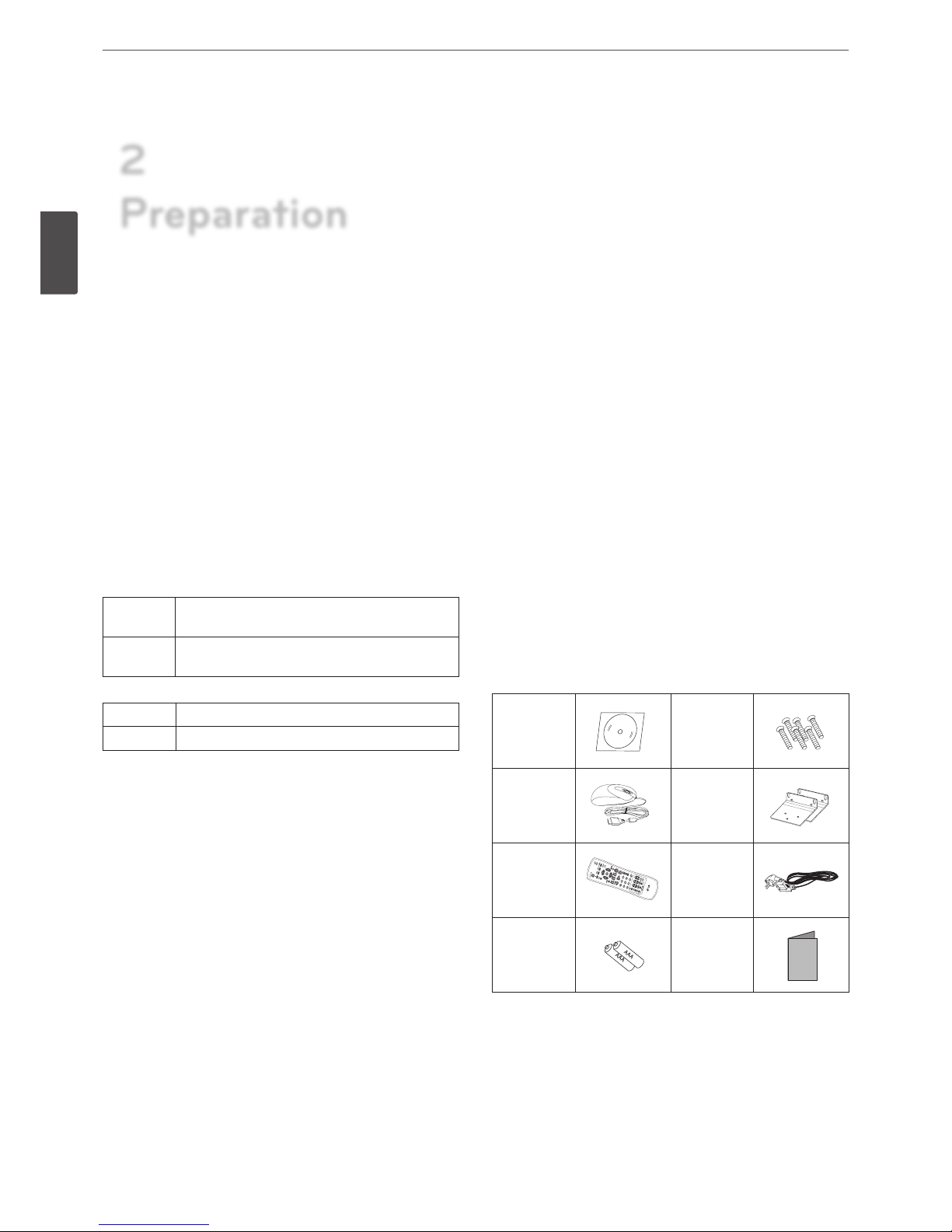
Accessories
CD (Software
and Owner's
Manual)
Screws
Mouse
Rack Mount
Bracket
Remote
Control
Power Plug
AAA type
batteries
Simple
Manual
2
Preparation
Preparation
9
2
Preparation
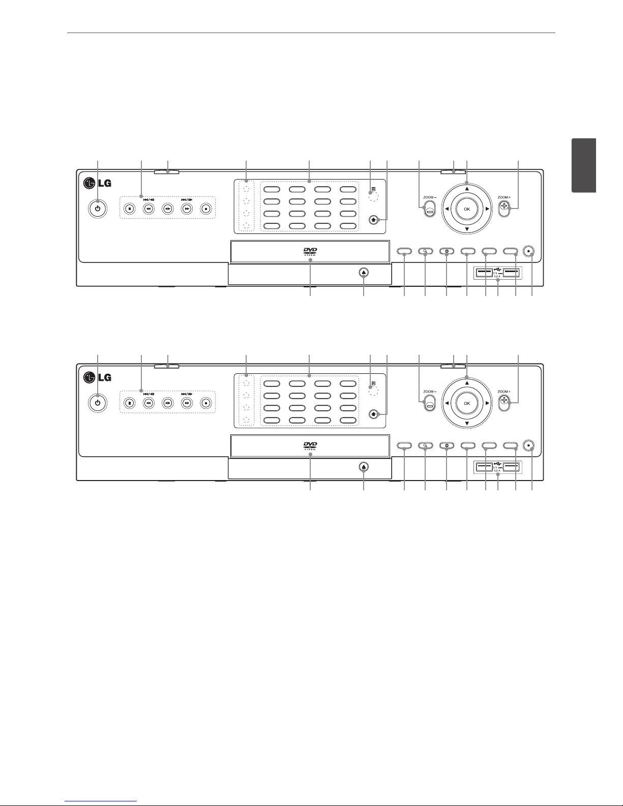
Front Panel
Front of the LRH7160D series
a b c d e f g h c i h
1
OSDNET
HDD
ALARM
BACK UP
2
PTZ3FOCUS+4IRIS+
SHIFT
5
INFO6ALM.OFF7FOCUS -8IRIS -
9
LOG
10/0
TEXT OFF11SET12CLEAR
13
COPY14MARK15MOVE16TOUR
LOG-IN VIEW CAM BACK
REC
SEARCH SETUP
j k l m n o p q r s
Front of the LRH7080D series
a b c d e f g h c i h
1
OSDNET
HDD
ALARM
BACK UP
2
PTZ3FOCUS+4IRIS+
SHIFT
5
INFO6ALM.OFF7FOCUS -8IRIS -
9
LOG0TEXT OFF SET CLEAR
COPY MARK MOVE TOUR
LOG-IN VIEW CAM BACK
REC
SEARCH SETUP
1
OSDNET
HDD
ALARM
BACK UP
2
PTZ3FOCUS+4IRIS+
SHIFT
5
INFO6ALM.OFF7FOCUS -8IRIS -
9
LOG
10/0
TEXT OFF11SET12CLEAR
13
COPY14MARK15MOVE16TOUR
LOG-IN VIEW CAM BACK
REC
SEARCH SETUP
j k l m n o p q r s
a 1
(Power): Turns DVR on or off. Press and hold for more than 2 seconds to turn on or off.
b
Playback Control Buttons
•M: Pauses playback.
•
c, C/aM
: Searches the recorded images in reverse or skips the recorded images.
•
ad
: Playback or reverse playback of recorded images.
•
v, V/Md
: Forward searches the recorded images or skips the recorded images.
•Z: Stops playback.
c
Front panel release button : Press these buttons to separate the front panel for HDD installation.
d
Indicator
• NET: Blinks when the network is connected.
• HDD: Lights when the HDD is accessed.
• ALARM: Lights when the alarm out is in progress.
• BACK UP: Lights when the data back up is in progress.
10
Preparation
2
Preparation
e
Channel Buttons: You can input a number with channel buttons. You can also use the channel buttons for sub-function with SHIFT
button (11 to 16 buttons of 8 channel DVR are used for sub-function without SHIFT button.).
• The LED in the button indicates the status as follows:
- Off: The current status is for live mode.
- Red: Recording mode.
- Blinks when an event occurs.
• Sub-functions
Button number Function Description
1 OSD Accesses or minimizes the System Control Bar (OSD).
2 PTZ Switches this unit to PTZ mode to control the connected PTZ camera.
3/7
FOCUS -
/ FOCUS +
Adjusts focus position.
4/8 IRIS - / IRIS + Adjust iris position.
5 INFO Displays the system information.
6 ALM.OFF
Cancels alarm activation and returns the system to the condition before the alarm was
activated.
9 LOG Displays the System Log List.
10 TEXT OFF Displays or disappears the text information if the recording data includes text data.
11 SET Registers the PTZ camera’s preset position.
12 CLEAR Deletes a memorized preset position.
13 COPY Displays the export menu.
14 MARK Sets the mark point for recording search.
15 MOVE Moves the camera to the preset position.
16 TOUR Tours all registered preset positions in the camera.
f
Remote Sensor: Point the remote control here.
g
SHIFT button: If you use the Sub-function of the channel button, the button is activated.
h
ZOOM + / -: Zooms in/out on playback window.
i
Arrow and OK Buttons
•
wsad
: Select or move between the menu options.
• OK: Confirms menu selections.
j
Disc Tray: Insert a disc here.
k
OPEN: Opens or closes the disc tray.
l
LOG-IN: Displays the User Log-In dialog box or logs out.
m
SEARCH: Displays the search menu.
n
SETUP: Displays the setup menu.
o
VIEW: Displays the split mode menu for MAIN Monitor and SPOT Monitor.
p
CAM: Displays the Monitor menu to set the first camera channel.
q
USB Port: Connects an external USB device for backup or playback.
r
BACK: Exits the menu or returns to the previous screen.
s
REC: Starts or stops instant recording.
Preparation
11
2
Preparation
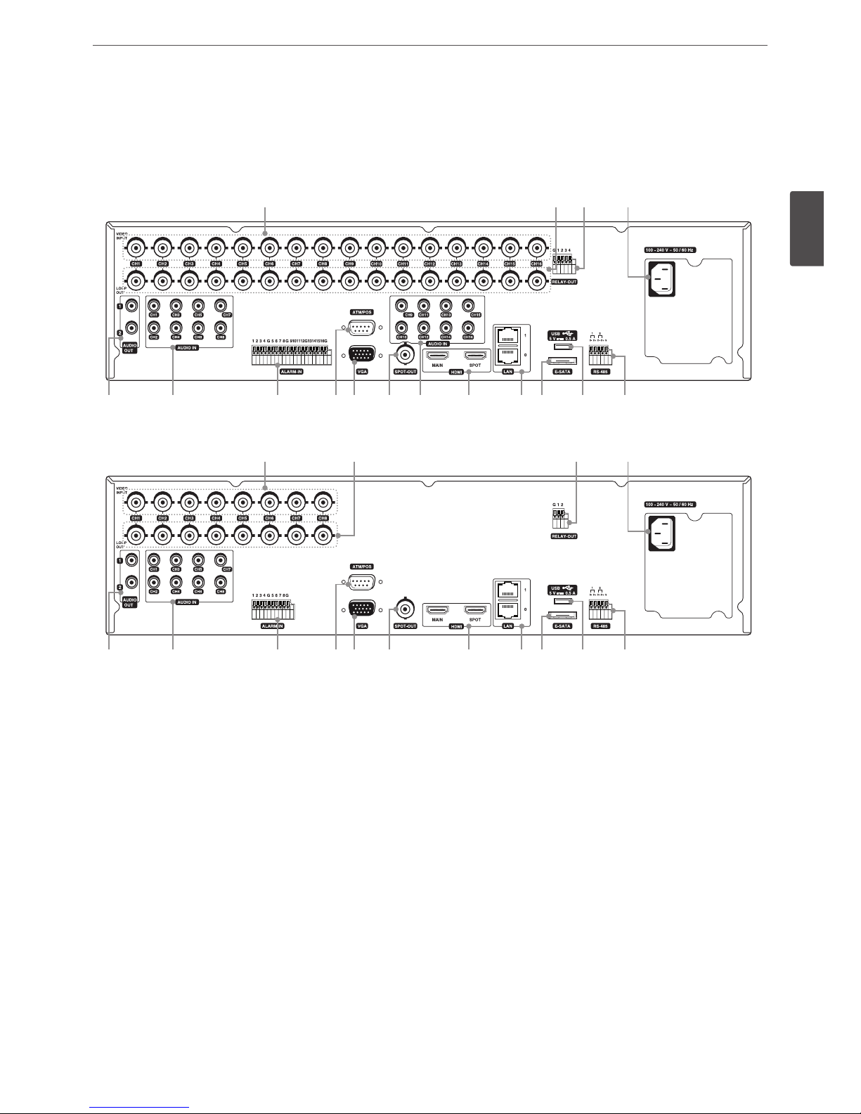
Rear Panel
Rear of the LRH7160D series
a b c d
e f g h i j f k l m n o
Rear of the LRH7080D series
a b c d
e f g h i j k l m n o
a
VIDEO INPUT: Connect the camera’s video output to these BNC connectors.
b
LOOP OUT: The signal from VIDEO INPUT connector is looped out to this connector.
c
RELAY-OUT Terminals: Output terminals for alarm (relay) signal.
d
Power Cord Inlet (AC IN): Connect the power plug.
e
AUDIO OUT 1 / 2: Connect to an active speaker with a built-in amplifier.
f
AUDIO IN: Connect the audio output of an external device.
g
ALARM-IN Terminals: Input terminals for alarm (relay) signal.
h
ATM/POS: Used to connect to a ATM/POS device.
i
VGA: Connect a VGA monitor.
j
SPOT-OUT (BNC Type Connector): Connect to spot monitor or display device.
k
HDMI: Connect to monitor or display device with HDMI inputs. (Interface for digital audio and video)
l
LAN Ports: Connect the ethernet 10/100/1000 Mbps network cable for controlling this unit via a PC network.
m
E-SATA: Connect the external SATA device.
n
USB Port: Connect an optional extension USB device.
o
RS-485 Terminals: Connect RS-485 compatible cameras.
12
Preparation
2
Preparation
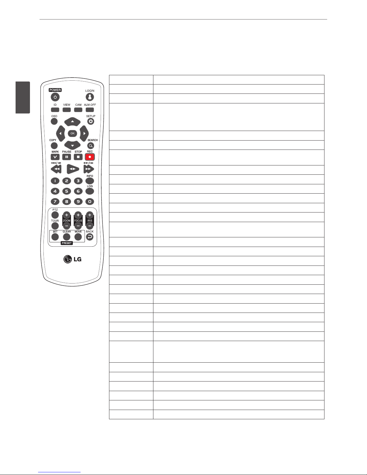
Remote Control
Button Description
POWER (1)
Turns DVR on or off.
LOGIN
Displays the User Log-In dialog box or logs out.
ID
Set the appropriate DVR system ID to operate via the IR Remote Controller when
using the multiple DVR. Press the ID button then press the number button within
2 seconds to select the system ID of the DVR. If you set the system ID to “0”, you
can control multiple DVR at the same time.
VIEW
Displays the split mode menu for MAIN Monitor and SPOT Monitor.
CAM
Displays the Monitor menu to set the first camera channel.
ALM.OFF
Cancels alarm activation and returns the system to the condition before the alarm
was activated.
OSD
Accesses or minimizes the system control bar.
SETUP
Displays the setup menu.
wsad
Selects or moves between the menu options.
OK
Confirms menu selections.
COPY
Copies the recording data to an external device.
SEARCH
Displays the search menu.
MARK
Sets the mark point for recording search. You can set the mark point during the
single or multi channel playback of recorded data.
PAUSE (M)
Pauses playback.
STOP (Z)
Stops playback.
REC (X)
Starts or stops recording.
c, C/aM
Searches the recorded images in reverse or skips the recorded images.
ad
Playback or reverse playback of recorded images.
v, V/Md
Forward searches the recorded images or skips the recorded images.
Number Buttons
Selects the PTZ preset number, ID or channel.
INFO
Displays the system information window.
LOG
Displays the System Log List window.
PTZ
Switches this unit to PTZ mode to control the connected PTZ camera.
TOUR
Tours all registered preset positions in the camera.
ZOOM + / -
Zooms in/out on the playback window.
If you press ZOOM(+) button during viewing a live channel in full screen mode or
playing back a channel in full screen mode, the digital zoom function is activated.
FOCUS + / -
Adjusts the focus of a camera.
IRIS + / -
Adjusts the iris of a camera.
SET
Registers the PTZ camera’s preset positions.
CLEAR
Deletes a memorized preset position.
MOVE
Moves the camera to the preset position.
BACK
Exits the menu or returns to the previous screen.
Installation
13
3
Installation
Connections
Precautions
• Depending on the camera and other equipment there are various ways to connect the unit. Please refer to the camera manual or manuals
for other devices as necessary for additional connection information.
• Be sure to switch off the camera before installation and connection.
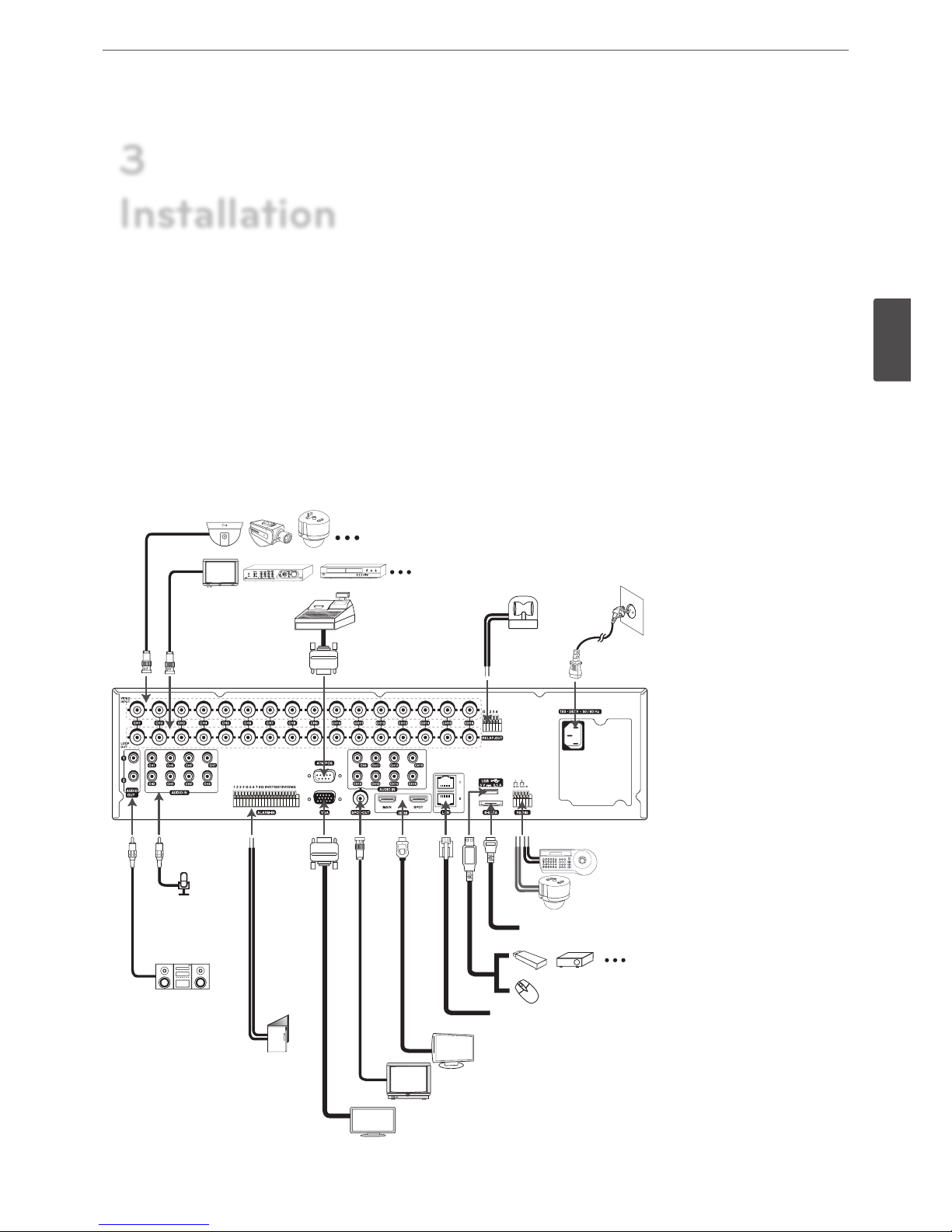
Basic Connection Overview
Connect audio
(line input).
Connect PTZ cameras,
DVRs or keypads (optional).
Connect BNC type monitor (SPOT).
Connect HDMI type monitor (MAIN or SPOT).
Connect the
alarm (relay).
Connect the coaxial-type cameras
Connect audio
amplifier.
Connect power
cord.
Connect an external USB device for
backup or playback.
Connect a mouse device.
Connect VGA monitor.
Connect the Monitor, DVR, VCR, or others.
Connect
alarm
sensors.
Connect the external SATA device.
Connect network cable for client control or IP camera input.
Connect ATM/
POS unit.
3
Installation
14
Installation
3
Installation
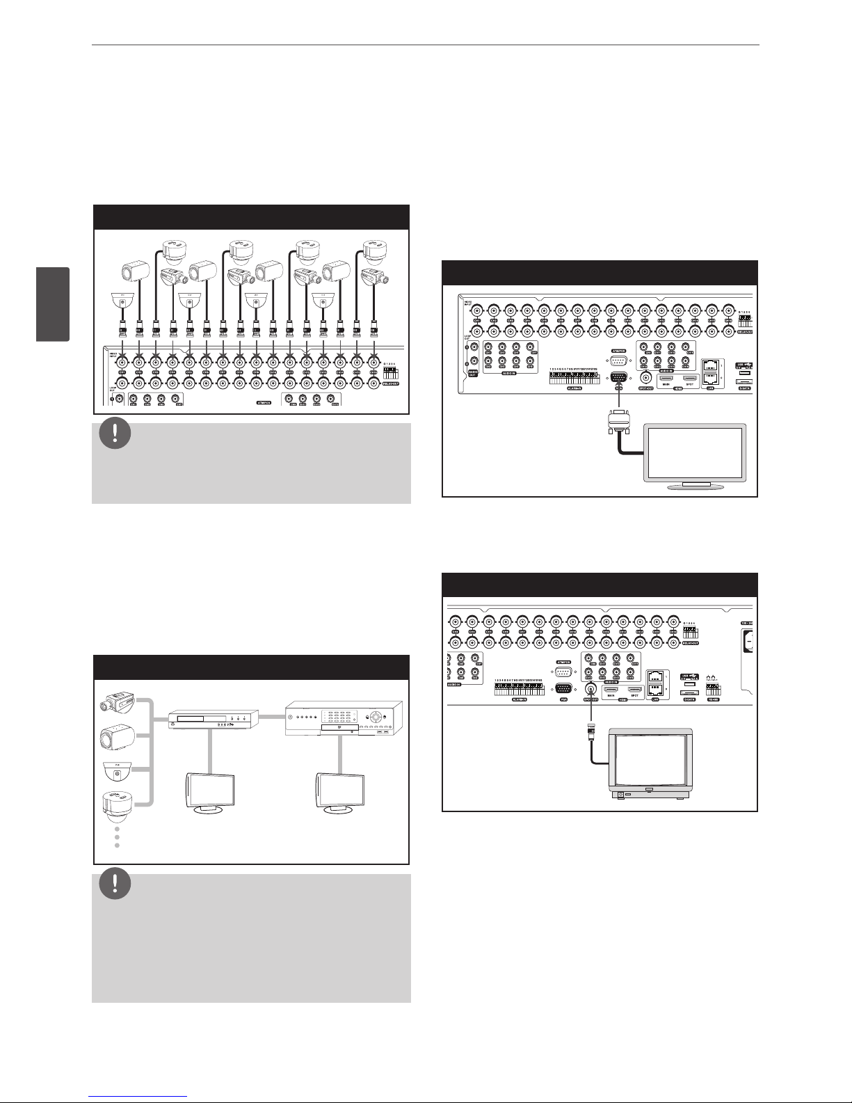
Connecting Camera
Connect the video output of your camera to the unit, using a
standard 75 Ω video coaxial cable with BNC connector.
LOOF OUT connector passes the video signal from VIDEO INPUT
connector to connect to other device.
Camera connection
NOTE
If the distance between the camera and DVR is too long, the noise
may be generated. In this case, we recommend you to ground
DVR’s power and not to ground camera’s power.
Connecting the video distributor
Connect the video signal of the camera to the input connector of
the video distributor using a 75 Ω video coaxial cable with BNC
connector. Connect the video output of the video distributer to the
VIDEO INPUT connector of DVR using a using a 75 Ω video coaxial
cable with BNC connector. Connect your monitor to the video
output connector of the video distributor.
Connecting the video distributor
Video distributor
Monitor Monitor
DVR
NOTE
• If the cable’s length is too long, DVR’s parts may be damaged
due to an external static electricity. Before connecting the
video cable, touch the end of the cable to DVR’s case to avoid
the risk of static buildup.
• Please check the images via a monitor after installation of the
video distributor.
Connecting Display device
This unit can be output simultaneously from the HDMI, VGA and
SPOT OUT jack. The video signal connection between the DVR and
the monitor.
VGA Monitor connection
Connect the VGA jacks on the rear of the unit to the corresponding
input jacks on the TV or monitor using the VGA cable.
VGA Monitor connection
SPOT Monitor connection
Connect the unit to the SPOT monitor using 75 Ω video coaxial
cables with BNC connector.
SPOT Monitor connection
Installation
15
3
Installation
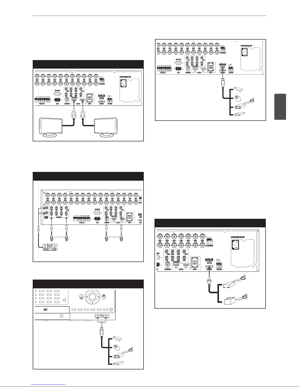
HDMI Monitor connection
Connect the unit to the HDMI monitor using a HDMI cable (Type A,
High Speed HDMI
TM
Cable).
HDMI Monitor connection
MAIN SPOT
Connecting Audio device
Connect the AUDIO OUT jacks on the unit to the mono audio in
jacks on your audio device.
Microphone and Speaker connection
Connecting USB device
USB device connection
USB Memory device
Insert the memory device into the USB port. The system
automatically recognizes the device. The system software can be
easily upgraded using a USB memory device.
USB External device
Connect the external device to the USB port.
(Example: External HDD or other external storage.)
Mouse
Connect the USB mouse to operate the functions of the DVR.
Connecting E-SATA device
You can use E-SATA storage for data back-up or recording.
E-SATA device connection
16
Installation
3
Installation
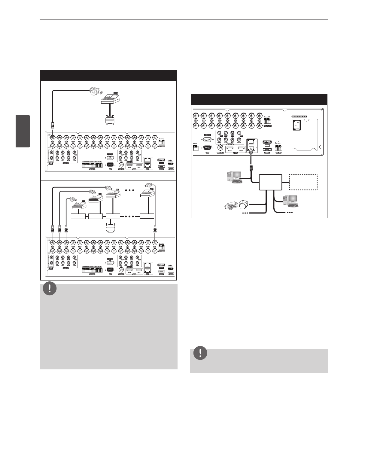
Connecting ATM/POS
Connect the ATM/POS unit to the ATM/POS port.
ATM/POS device connection
NOTE
• The following device has been tested and compatibility is
ensured. When you use the multiple ATM/POS device, use the
recommended device.
- AVE Products
› VSI-PRO: Video serial interface
› Regcom: RS-485 networker
› Hydra: RS-485 to RS-232 converter
• The installation and connection work should be done by
qualified service personnel or system installers and should be
conformed to all local codes.
Connecting Network
You can control and monitor the system via network. With
the remote control (monitoring), you can change the system
configuration or monitor the image via network. After the
installation, check the network settings for the remote control and
monitoring work.
Network connection
Router
Broadband
Service
Router
Broadband
Service
LAN connection
Connect the LAN port to an available 10/100/1000 base-T port with
a straight ethernet cable (not supplied). The NET indicator on the
front panel will be lit.
IP Camera connection
Connect the IP camera. After the installation, check the IP camera
settings on the setup menu.
Automatic network configuration
The DVR can automatically obtain and configure the network
interface via DHCP.
Manually configure network
The DVR may be manually configured by assigning an IP address,
subnet mask, gateway and DNS.
NOTE
This unit can be supported IPv4 and IPv6 network.
Installation
17
3
Installation
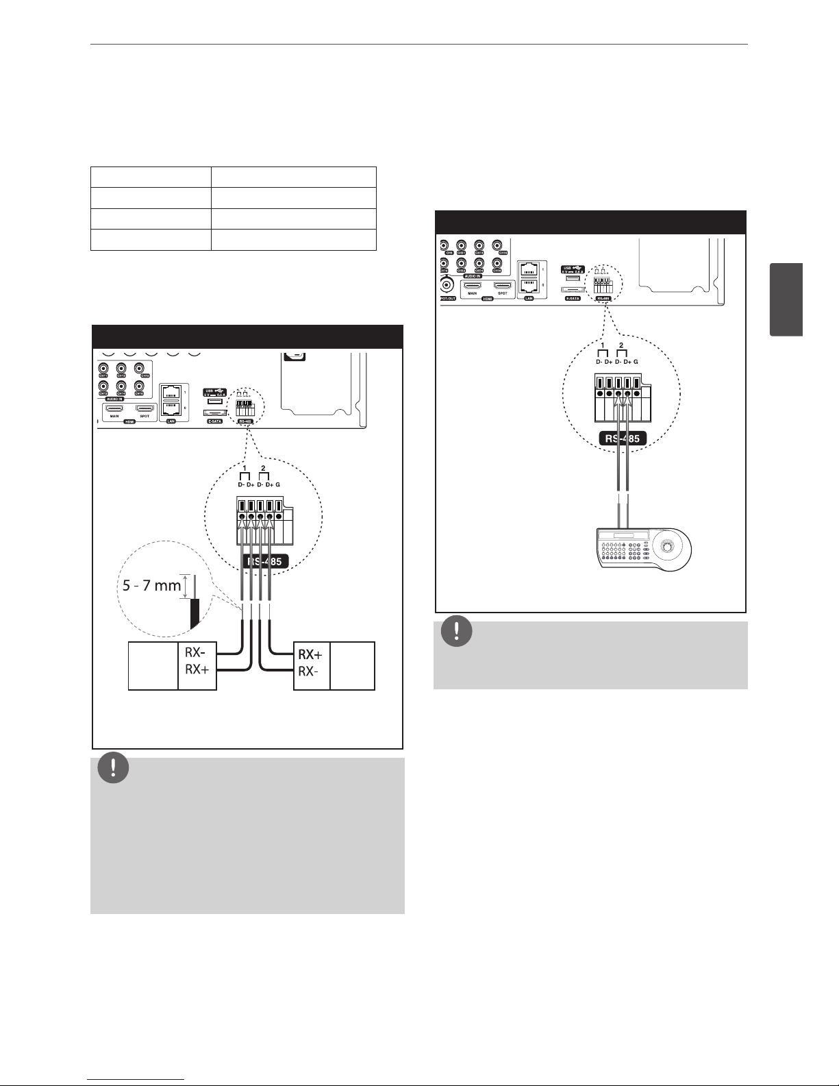
Connecting RS-485 device
This DVR has two data terminals. Use this port to connect PTZ
cameras, DVRs or keypads (optional).
RS-485 Terminal Description
D - (DATA -) Data Transmission/Reception
D + (DATA +) Data Transmission/Reception
GND Shield
Connecting the PTZ device
Connecting the PTZ serial communication lines to the
RS-485 terminal.
PTZ device connection
PTZ units
(RS-485 type)
PTZ units
(RS-485 type)
NOTE
• When connecting lines, connect the “D -” of the DVR to “RX -”
of the PTZ unit and “D +” of the DVR to “RX +” of the PTZ unit
correctly.
• Recommended initial data are 9600 Baud Rate, 8 Data bits,
1 Stop bit and No parity.
• When connecting PTZ cameras to DVRs it is necessary to set
the setup menu for this unit according to the RS-485 settings
of the camera and DVRs.
Connecting LKD1000 controller
Connect the LKD1000 controller to control the DVR. (Refer to the
manuals of the LKD1000 controller for more details.) The LKD1000
controller has to be connected to the 2 (DATA 2) port as shown
illustration. If you connect the LKD1000 controller to the 1 (DATA 1)
port, the LKD1000 controller will not be activated.
LKD1000 controller connection
LKD1000 Controller
TX+TX-
NOTE
Do not connect a PTZ camera and LKD1000 controller to the D1 or
D2 port at the same time. It may cause a malfunction.
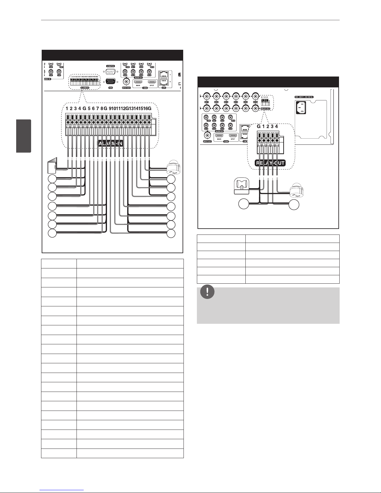
Connecting Alarm Input and Alarm
Output
Alarm terminals are used to connect the alarm devices such as
sensors, door switches, etc.
Alarm Input
You can connect up to 16 alarm sensors (LRH7080D: 8 alarm
sensors). Each alarm sensor should be connected with G (GND).
The signal state is adjustable to N/O (Normal Open) or N/C (Normal
Close) through the setup menu.
18
Installation
3
Installation
Sensor input connection
Alarm sensor Alarm sensor
Terminal No. Description
1 Sensor Input 1
2 Sensor Input 2
3 Sensor Input 3
4 Sensor Input 4
G Ground
5 Sensor Input 5
6 Sensor Input 6
7 Sensor Input 7
8 Sensor Input 8
G Ground
9 Sensor Input 9
10 Sensor Input 10
11 Sensor Input 11
12 Sensor Input 12
G Ground
13 Sensor Input 13
14 Sensor Input 14
15 Sensor Input 15
16 Sensor Input 16
G Ground
Alarm Output
Connect the alarm device to the alarm output. Alarm signal outputs
when an event occur.
Alarm output connection
Alarm device
Alarm device
Terminal No. Description
G Ground
1 Alarm Output 1
2 Alarm Output 2
3 Alarm Output 3
4 Alarm Output 4
NOTE
The internal switching relays are rated for 0.3 A at 125 V AC or 1 A
at 30 V DC. If the electric current is higher than that the unit can
be damaged.
Installation
19
3
Installation
HDD INSTALLATION
Note for Hard Disk Drive
The internal hard disk drive (HDD) is a fragile piece of equipment.
Please follow the guidelines below when using the DVR to protect
against possible HDD failure. We recommend that you back up your
important recordings onto an external backup device in order to
prevent accidental loss.
Make sure that the power is turned OFF when attaching or
removing the HDD.
• Do not move the DVR while the power is on.
• Do not use the DVR in excessively hot or humid places, or in
places that may be subject to sudden changes in temperature.
Sudden changes in temperature can cause condensation to
form inside the DVR. This can be a cause of HDD failure.
• While the DVR is switched on, do not unplug from the wall
socket or switch the electricity off from the breaker switch.
• If there’s a power failure while the DVR is on, some data on the
HDD may be lost.
• Do not drop the HDD. Also do not put the metallic object such
as coins or screwdrivers into the HDD tray.
• When a power failure occurs during recording, avoid adding,
replacing or transporting the HDD as the recorded data may be
erased. In this case, turn the power back on to boot up the unit
normally with the HDD that was being used at the time of the
power failure attached. Then add, replace, or transport the HDD.
• The HDD is very delicate. Handle the HDD with care and follow
the precautions below because even a tiny shock may damage
the internal components of the HDD.
- Do not place the HDD on the desk or table directly. Put a
thick cushion under the HDD because even a small shock
may damage the internal components of the HDD.
- Do not use an electric screwdriver. Vibrations and shocks
caused by an electric screwdriver may damage the internal
components of the HDD.
- When replacing the HDD, do not knock the HDD with other
components such as another HDD and the HDD tray.
- Do not knock the HDD with tools such as a driver when
replacing the HDD.
• Protect the hard disk drives from static electricity.
Installing the Hard Disk Drive
You can install up to 6 HDDs.
Improper installation or setup may disturb HDD recognition or
normal product operation. So you should consult with an expert
from the store where the product was purchased.
1. Disassemble the front panel by pressing the release button on
the front panel.
2. Loosen the screws and detach the hard disk mounting brackets
from the units.
3. Attach the HDD onto the hard disk mounting brackets with four
screws.
4. Attach the hard disk mounting brackets with the screws.
5. Close the front panel by hanging the bottom hook after push
the Front panel release button.
6. When you turn the power of the unit on, the new HDD is
detected and formatted automatically.
CAUTION
You should install the hard disk drive from 1 to 6 in order.
Replacing the Hard Disk Drive
Turn the power of the unit off and detach the power plug from the
outlet.
1. Disassemble the front panel by pressing the release button on
the front panel.
2. Loosen the screws and detach the hard disk mounting brackets
from the units.
3. Replace the new HDD.
4. Close the front panel by hanging the bottom hook after push
the Front panel release button.
5. After replacing the hard disk drive, insert the power plug into
the outlet and turn the power of the unit on. The new HDD is
detected and formatted.
automatically.
NOTE
Do not use an electric screwdriver to fix them.
Recommended HDD
For the latest recommended HDD list, please visit
http://www.lgecommercial.com
NOTE
If you do not use the recommended HDD, the system may not be
operated normally.
20
Installation
3
Installation
System Operation
1. Turn on the unit. System booting will commence. The LG logo
image will be displayed on the main monitor during the system
booting.
2. When the booting is completed the live window will be
displayed. Click the icon on the system control bar or press
the LOGIN button on the remote control to display the log-in
window.
3. Select a user name by using the mouse or arrow and the OK
button on the remote control or front panel. For the first time,
you can select the ADMINISTRATOR user name only. You can
register a new user with various access rights using the user
setup menu.
4. Enter the password by using the virtual keyboard. (Note that the
default administrator password is “000000”.)
5. Click the [OK] icon.
You can see the live screen and operate the system.
NOTE
• This DVR is based on a VGA monitor using OSD. We
recommend you to using the VGA monitor with this unit. If
you use a composite monitor, the OSD quality may be low to
read it.
• If the DVR is turned off accidently and then turned on again,
the DVR may take a long time to be rebooted.
System Shutdown
1. First, you must stop playback and exit the setup menu. In
playback, press STOP.
2. Press and hold 1 (POWER) button until the beep sounds and
the logout window will be displayed.
3. Enter the password by using the virtual keyboard.
4. Click the [OK] icon. The system will shutdown.
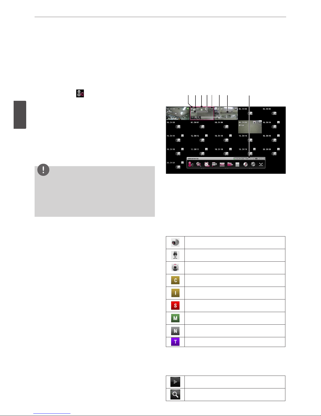
General Explanation of the Live
Screen on the Main Monitor
Main Monitor Screen
a b cde f g h
a
Channel Number
Displays the channel number.
b
Channel Name
Displays the edited channel name.
c
Selected Channel
Displays the selected channel with red box.
d
Channel FPS
Displays the channel FPS value.
e
Camera Status Icon
Displays the PTZ camera status.
Displays the input audio status.
Displays the IP camera status.
Gold “C” indicates continuous recording.
Gold “I” indicates Instant recording.
Red “S” indicates sensor triggered recording.
Green “M” indicates motion detection recording.
Gray “N” indicates the channel is not being recorded.
Violet “T” indicates text event recording.
f
Quick Buttons
The Quick Buttons will appear when the mouse is moved to
the camera's live screen. You can use the following functions by
clicking it for the selected channel.
You can use the playback function.
You can use the digital zoom function.
Installation
21
3
Installation
You can control the PTZ Camera. (optional)
g
Live Screen
Displays the current surveillance live screen.
h
System Control Bar
Displays the CPU usage and Data traffic
level of IP cameras.
Displays date and time.
( )
Login (Logout) : Display the User Log-In
dialog box or logs out.
Search: Displays the search menu.
Alarm Off: Turns the alarm off.
Camera: Displays the Monitor menu to
set the first camera channel.
Split mode: Displays the menu for
selecting the screen division.
Video Export: Displays the export menu.
System Log: Displays the system log list
window.
System Information: Displays the system
information window.
Setup: Displays the setup menu.
Minimizes the System Control Bar.
NOTE
• To display / minimize the system control bar
To display or minimize System Control Bar, press OSD after
pressing the SHIFT button on the front panel or click
or
in the System Control Bar.
• You can also use the system control's options by clicking the
right button of the mouse on the Main Monitor screen.
• When data signal color of IP camera is changed yellow or red,
reduce bit rate, frame rate, resolution and connections of IP
camera.
Moving the Channel's Position
You can change the camera channel's position in a split screen of
the Main Monitor.
1. Select a desired channel by clicking the left button of the
mouse.
2. Drag and drop it to a desired location and the channel's position
will be changed.
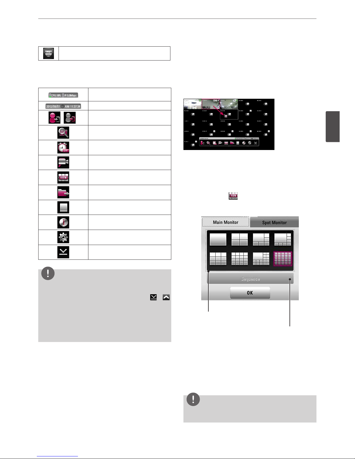
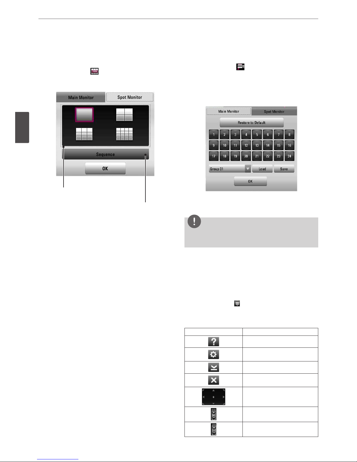
Selecting the Main Monitor screen mode
You can select the live screen mode to display a full, 4-split, 6-split,
8-split, 9-split, 16-split, 17-split or 25-split screens on the main
monitor.
1. Press VIEW or click icon in the system control bar.
2. Select [Main Monitor].
3. Select a screen mode.
Screen split mode
Sequence mode
• Full Screen Mode: You can view the live window in full
screen mode.
• 4, 9, 16, 25, 1+5, 1+7 and 1+16 Split Mode: Displays selected
split screens on the main monitor.
• Sequence: You can view all the channels in sequence. You
cannot use sequence mode with the 25 split (LRH7080D
series: 16 split).
4. Select [OK] and press OK to confirm your selection.
NOTE
To display the screen you want to watch in full screen mode,
double click the desired channel.
22
Installation
3
Installation
Selecting the Spot Monitor screen mode
You can select the live screen mode to full, 4-split, 9-split or 16-split
screens on the spot monitor.
1. Press VIEW or click the icon in the system control bar.
2. Select [Spot Monitor].
3. Select a screen mode.
Screen split mode
Sequence mode
• Full Screen Mode: You can view the live window in full
screen mode.
• 4, 9 and 16 Split Mode: Displays selected split screens on the
spot monitor.
• Sequence: You can view all the channels in sequence. You
cannot use sequence mode with the 16 split (LRH7080D
series: 9 split).
4. Select [OK] and press OK to confirm your selection.
Grouping channel
You can group channels you want.
1. Press CAM or click the icon in the system control bar.
2. Select [Main Monitor] or [Spot Monitor] on the menu.
3. Select a camera number for including group.
- [Restore to Default] : Reset channels to ascending sort and
change the [Split Mode] to 25 split. (LRH7080D series: 16
split)
4. Select group number on the drop-down list.
5. Click [Load] or [Save] button to configure your group.
6. Select [OK] and press OK to confirm your selection.
NOTE
The [Split Mode] changes according to a number of selected
cameras.
PTZ Camera Control
You can control the cameras connected via the data port of RS-485
terminal or Network. You must set the configuration between the
PTZ camera and the DVR.
1. Select the PTZ camera channel on the main monitor you want
to control.
2. Press PTZ or click the icon that appears when the mouse is
moved to PTZ camera's screen.
Virtual PTZ remote control is displayed on the main monitor.
3. Use each item to control the PTZ camera.
Button Function
Displays the PTZ control guide.
Displays the setup menu of the PTZ
camera.
Minimizes PTZ virtual remote control.
Removes the PTZ virtual remote
control.
Use to pan/tilt the camera.
You can select the Pan/Tilt/Zoom
speed.
You can adjust the camera zoom.
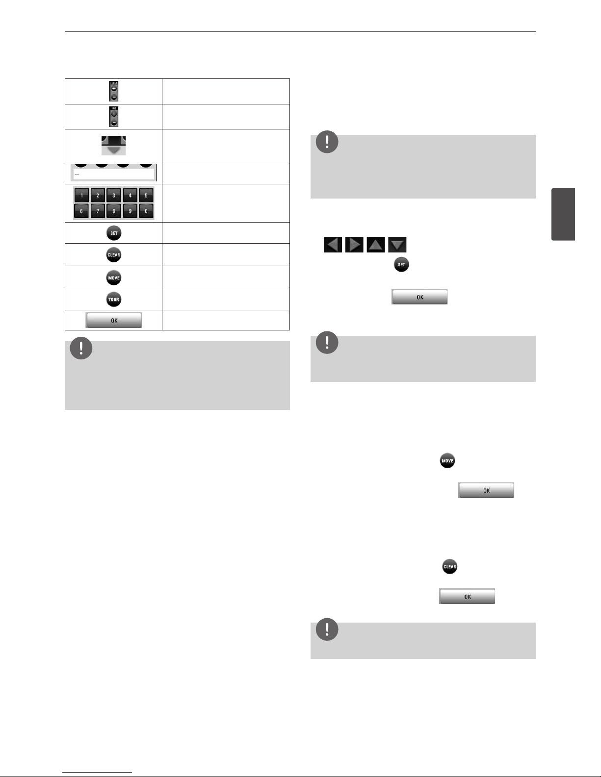
Installation
23
3
Installation
You can adjust the focus of a camera
manually.
You can adjust the iris of a camera
manually.
Displays or disappear the preset
control options in the virtual PTZ
remote control
Displays the Selected Preset number.
To input the preset number.
To register preset positions.
To delete a memorized preset
position.
To move the camera to the preset
position.
To start a preset tour.
Confirm the preset position.
NOTE
You can use some options by clicking the right button of the
mouse in PTZ camera control mode.
• PTZ Control Guide: Shows the guide for using the mouse.
• Exit: Exits from the PTZ camera control mode.
Preset Settings
Preset position is the function to register camera monitoring
positions (preset positions) associated with position numbers.
By entering the position numbers, you can move cameras to the
preset positions.
NOTE
• To activate this function, you need to register the preset
positions of the PTZ cameras.
• ONVIF preset may not be operated properly with this unit.
To Register Preset Positions
1. Move the camera to a point you wish by using the
, , , buttons.
2. Press SET or click the icon.
3. Select the preset number you wish to register.
4. Press OK or click the icon.
The position and its number are memorized.
5. Repeat steps 1 to 4 to add additional positions.
NOTE
Preset numbers from 0 to 255 are available on this unit but the
actual preset range differs depending on PTZ cameras.
Changing to a Picture in a Preset Position
The following function is available only with cameras provided with
the preset function. The preset function makes the combination
camera move to the programmed preset position. It is necessary to
program preset positions for the combination camera beforehand.
1. Press the MOVE button or click the icon.
2. Use number buttons to enter the memorized preset position’s
index number then press OK or click the
icon.
The camera moves to the preset position and the picture of the
camera in that position appears on the monitor.
To Clear the Preset Position
You can clear a memorized preset position.
1. Press the CLEAR button or Click the icon.
2. Use number buttons to enter the memorized preset index
number then press OK or Click the
icon to
clear the preset positions.
NOTE
This function may not be available depending on PTZ cameras.
24
Installation
3
Installation
To Tour The Preset Positions
You can tour all preset positions.
1. Press the TOUR button or Click the icon.
All registered preset positions in the camera will be selected
and the camera position image will be switched on the active
monitor.
2. You can stop the tour by pressing the TOUR
button or clicking the
icon.
Setup for PTZ Cameras
You can adapt the camera to your requirements by setting up the
respective items in menus.
1. Click the icon.
The setup menu appears in the selected window of the main
monitor.
2. Use , , , , , , , and
buttons to set the options.
NOTE
• Refer to the manuals of the PTZ camera for more details.
• Some PTZ cameras may not be operated properly with this
unit.
• You cannot control the other functions when the PTZ virtual
remote control is displayed.
Using the Digital Zoom function
You can enlarge the current screen 2 times using the digital zoom
function on one live channel with full screen mode or one channel
playback with full screen mode.
1. Press ZOOM(+) button during viewing a live channel in full
screen mode or playing back a channel in full screen mode.
2. You can use the zoom screen as following.
• You can move the position of the zoom screen by using the
w/s/a/d
buttons.
• You can move the zoom screen by using the mouse. Drag &
drop a point to the specific point to move the zoom screen.
3. Press BACK button to exit.
NOTE
The zoom function is deactivated when below case.
• When double click the left mouse button.
• Press the specific channel or function button which front
panel of the unit.
• Press the STOP button during the playback.
You can use some options by clicking the right button of the
mouse in the digital zoom mode.
• Digital Zoom Control Guide: Shows the guide for using the
mouse.
• Exit: Exits from the digital zoom mode.
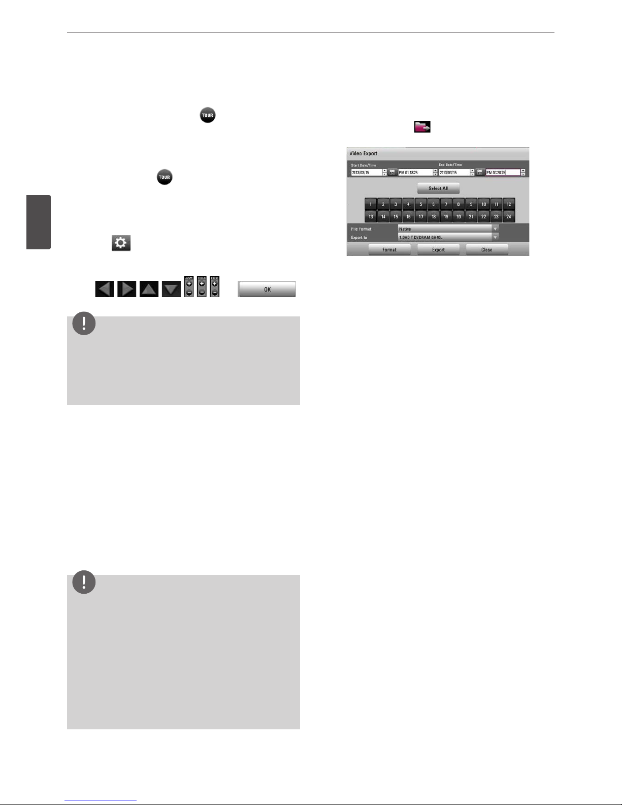
Export the recorded data
This unit can manually copy recorded images and audio from builtin HDD to the external recording devices.
1. Press COPY or click the icon in the system control bar.
The [Video Export] menu appears.
2. Set the [Start Date/Time] and [End Date/Time] to search.
•
a/d/w/s
: Moves to the options.
•
w/s
: Sets the selected option.
• OK: Selects option or confirms the setting.
3. Select the channel number and press OK. Repeat this step to
select multi channels.
4. Select the one of file format on the drop-down list of the [File
Format].
• Native: The Native file is saved with the extention of “*.exp”.
The saved native file can playback using the Export Viewer
program.
• AVI LG: To playing AVI LG file, you have to install the LG DVR
Codec. If you install the LG Network Client, do not need to
install the LG DVR Codec.
• AVI: If you select AVI file format, it can play on any media
player.
5. Select [Export to] then press OK.
6. Use
w/s
to select a target device to export.
7. Press OK to confirm it.
8. Click the [Export] icon to start exporting. The exported data
will be authorized by the unit before saving and it can only be
played back with the exclusive player.
Installation
25
3
Installation
NOTE
• Check the export device before you proceed.
• You can also use the COPY button on the front panel for
export function.
• You can export the recorded data only in the live mode.
• If you use the external device, the external device has to be
formatted on this unit.
1. Connect the external device to the USB port on the front
or the rear of the DVR.
2. Select the [Format] icon then press OK.
Confirm window is displayed after format is completed.
3. Select [OK] and press OK to close the window.
• Check the size of the selected data and free space of the
external device. If the device does not have enough space,
create space on the device or erase the previously stored data.
• Export can not be executed while the backup is in progress.
• You can search the exported data with the supplied viewer
software.
• When you export the recorded data, the video data, audio
data, the system log and event log data will also be exported.
• When you export the recorded data the export viewer
program will also be exported in the [ExportViewer] folder of
the device. The exported data file name is made automatically
as the [Channel name_export date_export time.exp] type.
• Do not remove the USB device while the export is in progress,
it may cause a malfunction.
• The warning message appears for the conditions listed below.
- When the start date/time and end date/time are the same
value.
- When the start date/time is later than the end date/time.
- The export media does not have enough space.
- When you set the time for data that does not exist.
• An external media has to be formatted on this unit to prevent
a malfunction.
• DVD+RW and DVD-RW discs have to be initialized before
using.
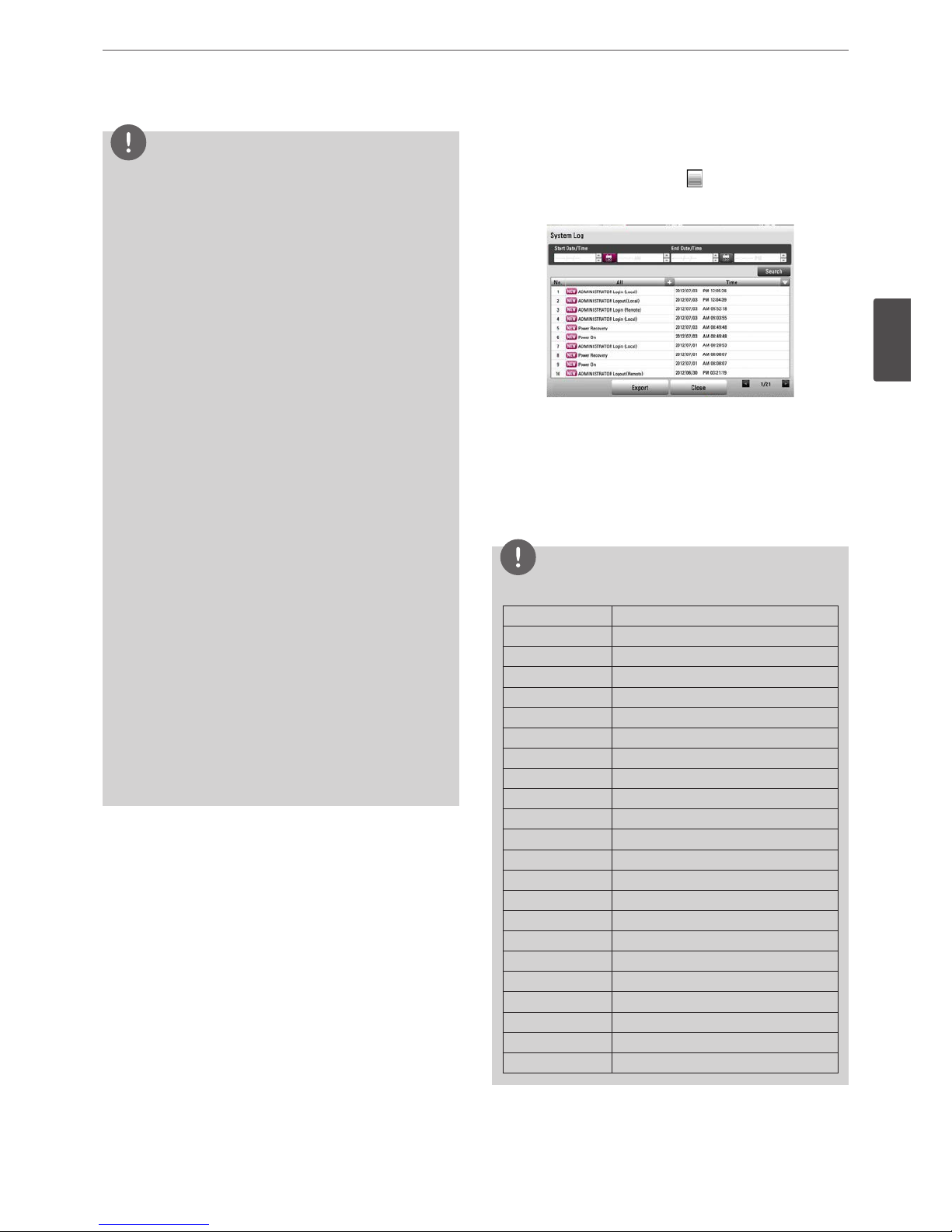
Viewing the System Log List
To view the system log list:
1. Press the LOG button or click the icon in the system control
bar. The system log list window is displayed on the main
monitor.
2. Set the [Start Date/Time] and [End Date/Time] to search.
•
a/d/w/s
: Moves to the options.
•
w/s
: Sets the selected option.
• OK: Selects option or confirms the setting.
3. Use
a/d
to see the previous or next log list.
4. Press the BACK button or click the [Close] button to exit the
window.
NOTE
Refer to the following system log list.
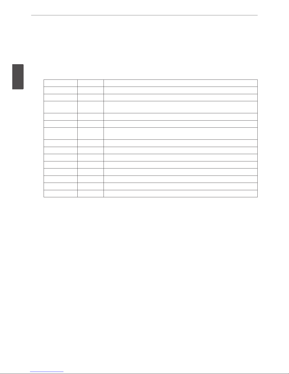
No. Log Message
1 Power On
2 Power Off
3 Login (Remote)
4 Logout (Remote)
5 Login (Local)
6 Logout (Local)
7 Configuration Changed
8 Configuration Imported
9 Factory Default Set
10 Power Recovery
11 Backup Started
12 Backup Finished
13 Backup Failed
14 Export Started
15 Export Finished
16 Export Failed
17 S/W Updated
18 HDD Damaged
19 HDD Added
20 HDD Deleted
21 HDD Formatted
22 HDD Changed
26
Installation
3
Installation
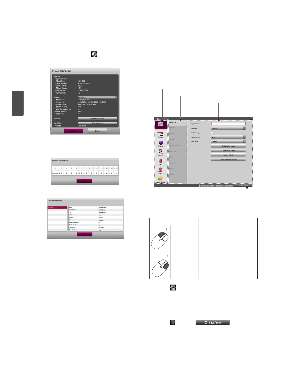
Viewing System Information
To view system information:
1. Press the INFO button or click the icon in the system control
bar. The system information window is displayed on the main
monitor.
• Ethernet 0 / 1: Displays the detail information of the
Network.
• Camera Information: Displays the detail information of the
camera framerate.
• HDD Information: Displays the detail information of the
HDD.
• Refresh: Updates the system information.
2. Press the BACK button or click the [Close] button to exit the
window.
Configuration menu
The features and options of the DVR are configured through the
menu. The operations of this unit can be set via a menu displayed
on the main monitor. You can select and set the operational
conditions by using the buttons on the front panel and the remote
control or using a Mouse connected to the unit.
Second level
First level
Third level
Informations
Using a mouse to set a menu
Use the left or right mouse buttons to set the menu.
Button Function
Left button
• Use to select a required item or
decrease the options value.
• If you double click the button,
you can see the selected
channel on the full screen.
Right button Use to increase the options value.
1. Click the icon on the System control bar with the left mouse
button to display a setup menu.
2. Click the desired option with the left mouse button to display
the second or third level menu options.
3. Click the desired option with the left mouse button.
4. Set the selected options value.
5. Click the icon or click icon repeatedly
to exit setup menu.
If the save message appears, click [OK] with the left mouse
button to save the settings.
Installation
27
3
Installation
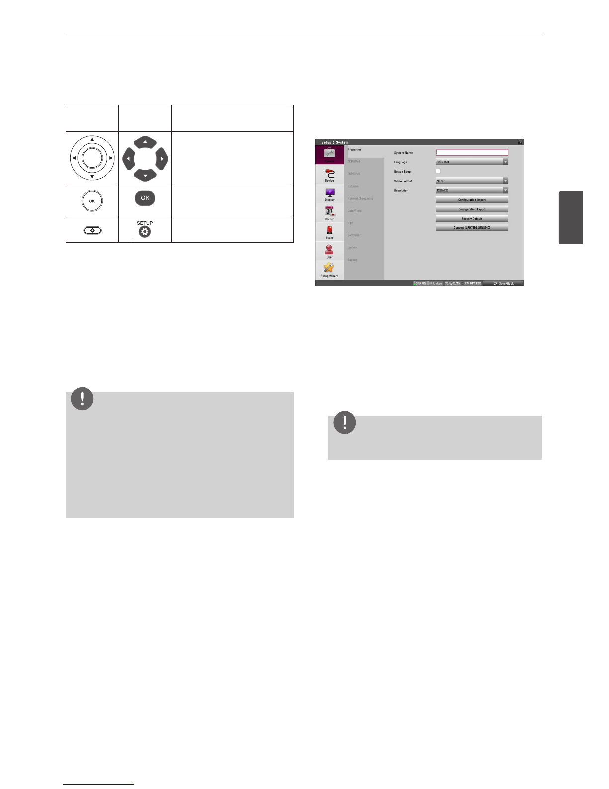
Setting the Menu Using the Front Panel Buttons or
Remote Control Buttons
Front Panel
Remote
Control
Description
Use these buttons to select the
menu options or adjust the
options value.
Select the option or confirm the
setting.
REC
SETUP
Return to the previous menu or
level.
1. Press SETUP to display the setup menu.
2. Use
w/s
to select the desired menu item, then press OK to
display the submenu.
3. Use
w/s
to select the desired submenu item, then press OK
to display the setting options.
4. Use
w/s
to select the desired option then press OK to set the
value.
5. Use
a/d
to select the desired setting then press OK to confirm
your selection.
6. Press BACK repeatedly to exit the Setup menu.
If the save message appears, select [OK] and press OK to save
the settings.
NOTE
• When you operate the function menu by using the remote
control and front panel buttons, both buttons are operated in
the same way to control the function menu.
• To use other functions of number buttons on the front panel,
follow the below steps.
1. Press SHIFT. The button indicator turns red.
2. Select the function button you want.
• All the operation explanations are based on using the remote
control.
System settings
Properties
• System Name: Enter the System name by using alphabetic letter,
numeric digit and symbols up to 21 characters.
• Language: Select a language for the setup menu and
information display.
• Button Beep: Marks up to activate the button beep. The button
beep is activated when using the buttons.
• Video Format: Selects the video format to NTSC or PAL according
to your video system format. If you change the video format, the
HDD is formatted with selected video format. After the HDD has
been formatted, the confirmation message is displayed. Select
[OK] and press OK. The system will reboot.
NOTE
All cameras must be disconnected before you change the
video format to prevent malfunction.
• Resolution: Sets the output resolution of the HDMI video signal.
• Configuration Import: Import the DVRs configuration data from
the USB memory stick.
• Configuration Export: Export the configuration data from this
DVR to the USB memory stick.
• Factory Default: You can reset the DVR to its original factory
settings. Some options cannot be reset. (date, time, daylight
saving, time zone and user password settings)
• Convert (LRH7160, LRN8240): Press the button to switch
between model LRH7160 and LRN8240.
28
Installation
3
Installation
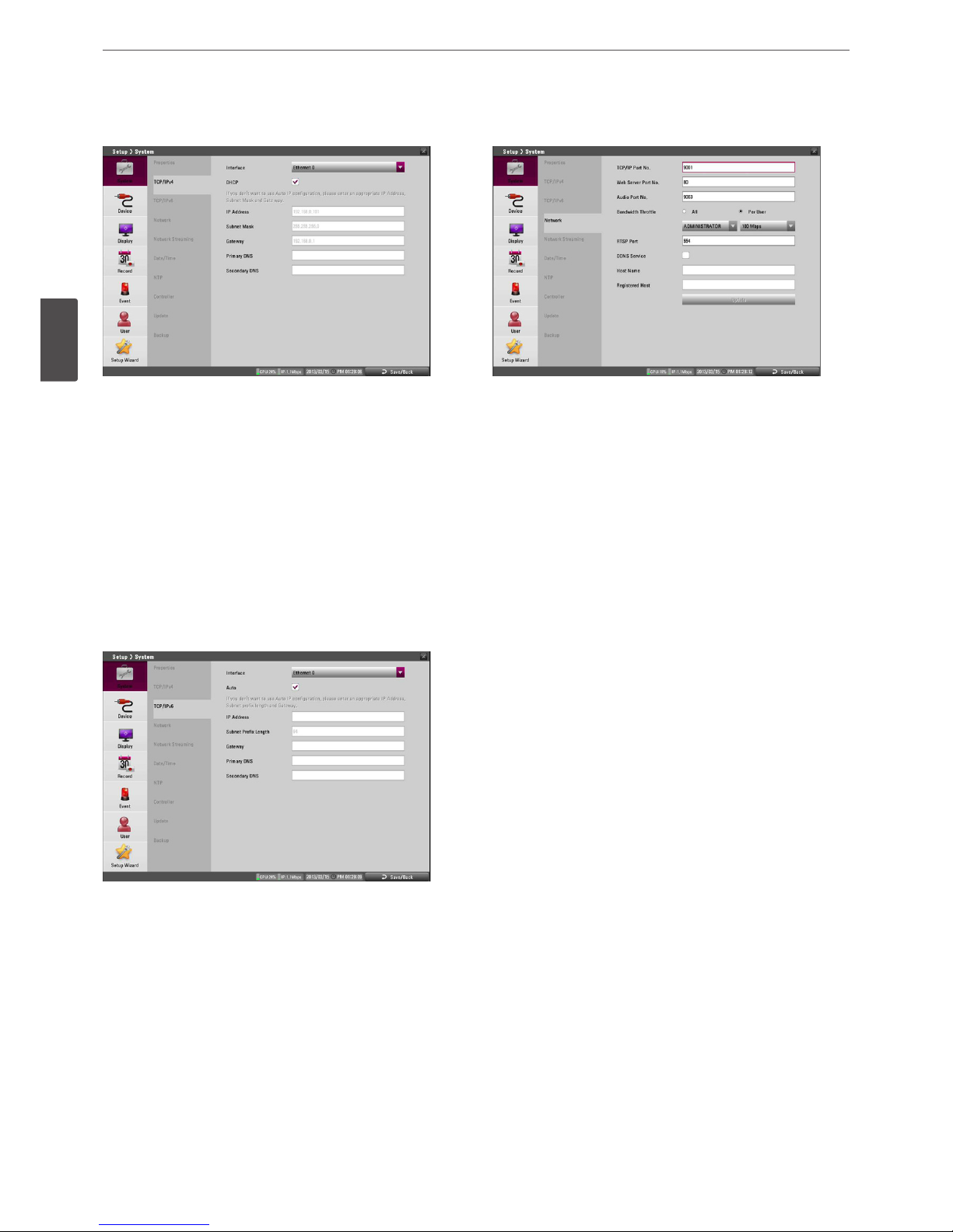
TCP/IP v4
• Interface: Select a LAN port you want to use (Ethernet 0 or
Ethernet 1).
• DHCP: Select this option when a DHCP server is installed on the
network to allow IP address assignment. With this setting, the IP
address is assigned automatically.
• IP Address: Enter the IP address.
• Subnet Mask: Enter the subnet mask address.
• Gateway: Enter the gateway address.
• Primary DNS: Enter the Primary domain name server that
translates the hostnames into IP address.
• Secondary DNS : Enter the Secondary DNS server address that
backups the Primary DNS.
TCP/IP v6
• Interface: Select a LAN port you want to use (Ethernet 0 or
Ethernet 1).
• Auto: Select this option to assign the IP address automatically.
• IP Address: Enter the IP address.
• Subnet Prefix Length: Enter the Subnet Prefix length.
An IPv6 prefix indicates the portion of the address used for
routing or identifying an address range.
• Gateway: Enter the gateway address.
• Primary DNS: Enter the Primary domain name server that
translates the hostnames into IP address.
• Secondary DNS : Enter the Secondary DNS server address that
backups the Primary DNS.
Network
• TCP/IP Port No.: Enter the TCP/IP Port number. You can watch
the live surveillance image over the network with the PC Client
program. The factory default port for transmission of video and
audio data is 9001. However in some cases it is better to change
this port number for added flexibility or security. You can edit
this port between 1025 and 65535.
• Web Server Port No.: Enter the Web Sever Port number. You can
watch the live surveillance image over the network with a web
browser. Typically the TCP port used by HTTP is 80. However in
some cases it is better to change this port number for added
flexibility or security. You can edit this port to 80 or between
1025 and 65535.
• Audio Port No.: Enter the Audio Port number. You can edit this
port between 1025 and 65535.
• Bandwidth Throttle: Select [All] or [Per User] to set the
bandwidth value.
- All: Set same bandwidth to all of users.
- Per User: You can set the bandwidth value per each user.
Select [User ID] from the left drop-down list. And then, set
the bandwidth from right drop-down list
• RTSP Port : Enter the RTSP Port number. You can edit this port
between 1 and 65535. Default Port number is 554.
• DDNS Service: Marks up to activate the DDNS function.
This free service is very useful when combined with the LG
DDNS Server. It allows the user to connect the IP device using
the URL, rather than an IP Address. This also solves the problem
of having a dynamic IP address.
• Host Name: Enter the host name you want to use.
You can not use the “www ”, “mail”, “http”, “ftp”, “com”, “lg”, “lge”,
“lgddns”, “lgeddns”, “ddns” for host name.
• Registered Host: The registered host name appears.
• Update: Register the host name you typed in [Host Name] to LG
DDNS server.
How to register DDNS host name
With the DDNS function, you can easily use LG DVR.
When you use the DDNS function for the rst time after you
purchased LG DVR
1. Displays the DVR setup menu.
2. Select [System] > [Network] option.
3. Marks up for the [DDNS Service] option.
4. Enter the host name in the [Host Name] option.
5. Press the [Update] button. If host registration is properly
completed, the host name will be displayed in the [Registered
Host] option. If the host name is not registered after updating,
Installation
29
3
Installation
please check network connection.
When you want to change DDNS host name
If you want to change the registered host name to new one, follow
as shown below.
1. Enter a new host name in the [Host Name] option.
2. Press the [Update] button. The confirmation window will be
displayed to change your host name.
3. Click the [OK] button. When host name is properly changed, the
changed host name will be displayed in the [Registered Host]
option. If host name is not changed after updating, please check
network connection.
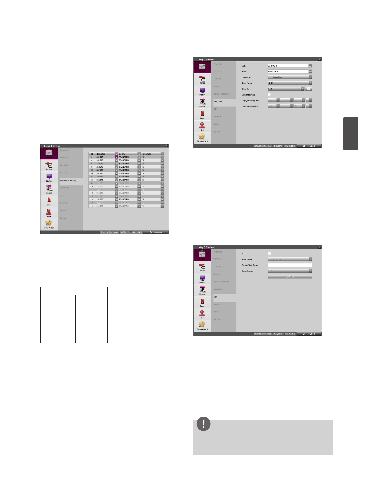
Network Streaming
• CH: Displays the channel number.
• Resolution : Selects the recording resolution.
• Quality: Selects the recording picture quality.
• Frame Rate: Selects the frame rate. The frame rate is the number
of transportable frames per second. According to resolution, the
frame rate is set automatically. If you wish to set manually, refer
to the below.
Resolution Frame Rate
NTSC
352*240 1, 3, 5, 7.5, 10, 15
704*240 1, 3, 5, 7.5
704*480 1, 3
PAL
352*288 1, 3, 5, 6, 7.5, 12.5
704*288 1, 3, 5, 6
704*576 1, 3
Date/Time
• Date: Select the current year, month and day.
• Time: Select the current time.
• Date Format: Select the date display format.
• Time Format: Select the time display format.
• Time Zone: Select the time zone in the area where the DVR is
installed.
• Daylight Saving: Mark up if you want to use the daylight saving
function.
• Daylight Saving Start: Select the Daylight Saving start time.
• Daylight Saving End: Select the Daylight Saving end time.
NTP
• NTP: Marks up, if you want to synchronize the DVR’s date and
time with those of the time server called NTP. (Network Time
Protocol) Specify the NTP server’s name.
• Time Server: For most cases select public. The DVR will obtain
the average time among 5 public servers (time.nist.gov, time-a.
nist.gov, time-b.nist.gov, ntp.nasa.gov, clock.isc.org).
• Private Time Server: Enter the private time server’s IP address or
host name using the virtual keyboard.
• Sync. Interval: You can set synchronized intervals with the NTP
time server to 1 day, 1 week, 1 month and 1 hour.
• NTP Test: Select [NTP Test] to test the NTP server.
NOTE
If the NTP option is not set to this system, there can be a
gap between the system time and actual time. Using NTP is
recommended.
 Loading...