

Page 1

Website: http://us.lge.com
Installation Manual
Electric Range
LRE30451S / LRE30755S
Please read these instructions thoroughly before
installing and operating the range.
P/No.: 3828W5U0512
Page 2
Part 1 SAFETY
1
BEFORE YOU BEGIN
PREPARE TO INSTALL THE RANGE
Remove all tape and packing materials before using
the range. Dispose all plastic bags after unpacking the
range. Never allow children to play with packing
materials.
IMPORTANT SAFETY INSTRUCTIONS
WARNING If the information in this manual is
not followed exactly, a fire or electrical shock may
result causing property damage, personal injury or
death.
WARNING
• ALL RANGES CAN TIP
• INJURY TO PERSONS COULD
RESULT
• INSTALL ANTI-TIP BRACKET
PACKED WITH RANGE
• SEE INSTALLATION
INSTRUCTIONS
Important Notes to the Installer
• Read all instructions contained in these installation
instructions before installing range.
• Remove all packing materials from the oven
compartments before connecting the electrical
supply to the range.
• Observe all governing codes and ordinances.
•
Be sure to leave these instructions with the consumer.
Important Note to the Consumer
Keep these instructions with your owner’s manual for
future reference.
• As when using any appliance generating heat, there
are certain safety precautions you should follow.
• Be sure your range is installed and grounded
properly by a qualified installer or service technician.
• Make sure the wall coverings around the range can
withstand the heat generated by the range.
• To eliminate the need to reach over the surface
elements, cabinet storage space above the elements
should be avoided.
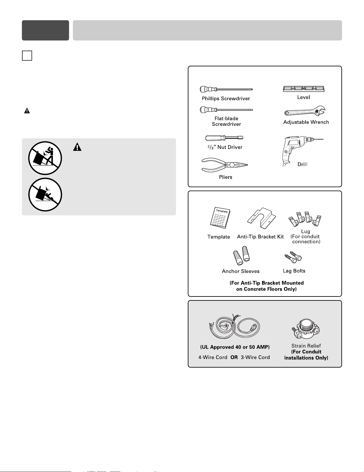
TOOLS NEEDED
PARTS PROVIDED
PARTS NOT PROVIDED
2
Page 3

Part 2 PREPARE TO INSTALL THE RANGE
2
INSTALLATION DRAWINGS
IMPORTANT
SAVE FOR THE USE OF THE LOCAL ELECTRICAL INSPECTOR.
CLEARANCES AND DIMENSIONS (Figure 1)
To install range refer to the following Figure 1.
For installation in CANADA, a Free-standing range is not to be installed closer than 12 mm from any
adjacent surface.
CAUTION
comply with the maximum allowable wood cabinet
temperatures of 194°F. Make sure the wall
covering, countertop and cabinets around the range
can withstand the heat (up to 194°F) generated by the
range. If not discoloration, delamination or melting
may occur.
This range has been designed to
IMPORTANT
or fire by reaching over heated surface units,
cabinet storage space located above the surface
units should be avoided. If cabinet storage is to be
provided, the risk can be reduced by installing a
range hood that projects horizontally a minimum of
5 inches beyond the bottom of the cabinets.
To eliminate the risk of burns
A = 30”(76.2 cm) For U.S.A
= 30”(76.2 cm) ~ 31”(78.7 cm) For CANADA
FIGURE 1 FIGURE 2
MINIMUM DIMENSIONS (Figure 2)
* 30”(76.2 cm) minimum clearance between the top of the cooking surface and the bottom of an
unprotected wood or metal cabinet; or 24”(60.9 cm) minimum when bottom of wood or metal cabinet is
protected by not less than 1/4”(6.4 cm) flame retardant millboard covered with not less than no. 28 MSG
sheet steel, 0.015”(0.381 mm) stainless steel, 0.024”(0.610 mm) aluminum or 0.020”(0.508 mm) copper.
** 15”(38.1 cm) minimum between countertop and adjacent cabinet bottom.
3
Page 4
Part 3 ELECTRICAL CONNECTIONS
3
ELECTRICAL CONNECTION
REQUIREMENTS
This appliance must be installed and grounded on a
branch circuit by a qualified technician in accordance
with the National Electrical code ANSI/NFPA NO. 70 latest edition.
All wiring should conform to Local and NEC. This
range requires a single-phase, 3 wire, A.C 120/208V or
120/240V 60Hz electrical system. Use only a 3-conductor
or a 4-conductor UL-listed range cord with closedloop terminals, open-end spade lugs with upturned
ends or similar terminations. Cord must have the
strain relief properly installed.
A range cord rated at 40 amps with 120/240 minimum
volt range is required. If a 50 amp range cord is used,
it should be marked for use with 13⁄8
connection openings.
This appliance may be connected by means of conduit
or power cord. If conduit is being used, go to page 6
3 wire conduit connections or page 7 for 4 wire
conduit connections.
” diameter
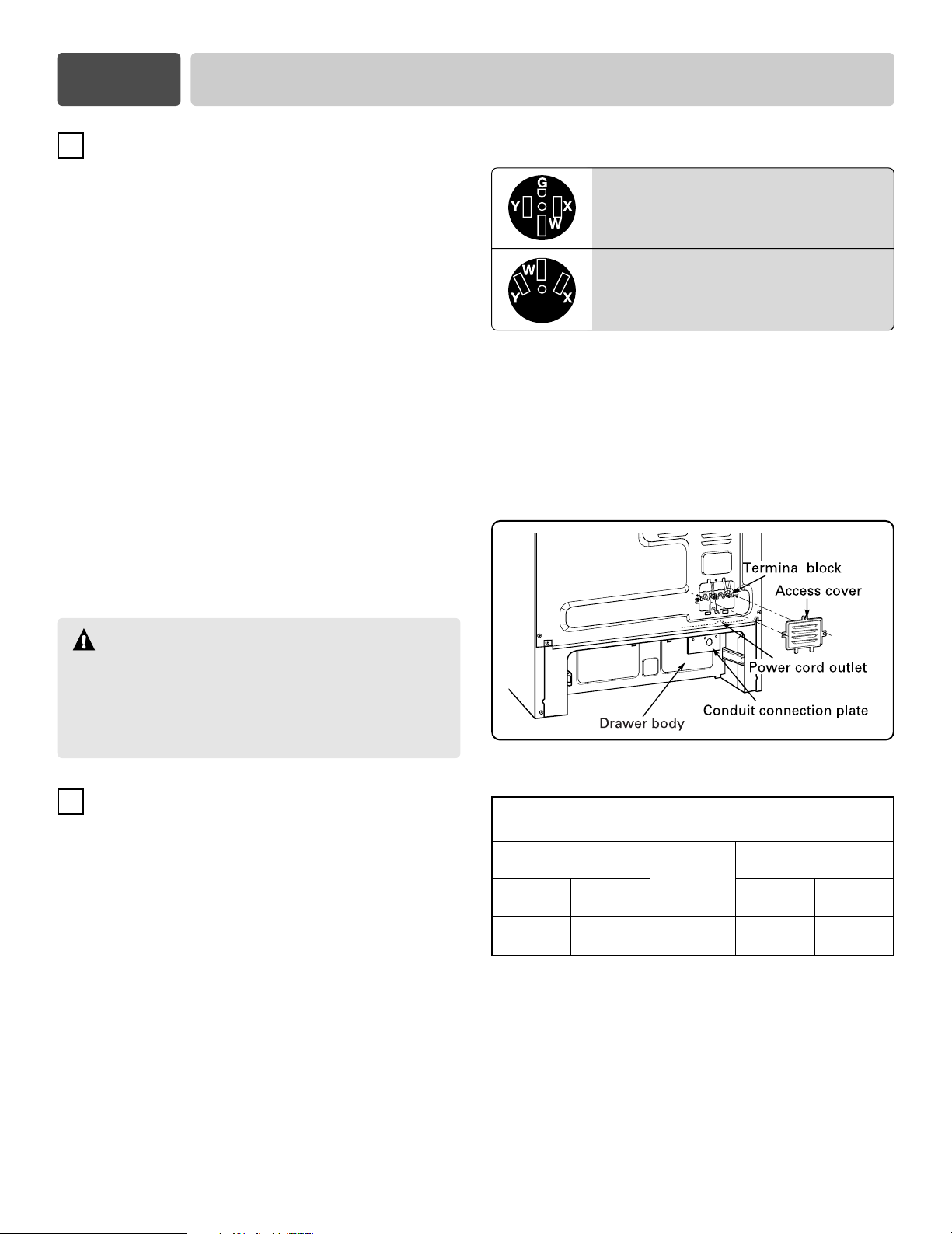
3, 4 - Wire electrical wall Receptacle types
4 Wire receptacle (14-50R)
3 Wire receptacle (10-50R)
FIGURE 3
Conduit connection plate is used for the installation of
power cord or conduit. For power cord, install it with
conduit connection plate as manufacturer supplied.
For conduit cord, remove the conduit connection plate
located below the rear of the drawer body and use the
conduit hole (11/8”) instead of power cord hole (13/8”).
(Refer to Figure 8.)
WARNING
New branch-circuit installations (1996 NEC), mobile
homes, recreational vehicles, and installations
where local codes do not allow grounding through
neutral require a 4-conductor UL listed range cord
or 4 wire conduit connection.
4
CONNECT RANGE CORD
The Rear Access cover must be removed. Loosen the
three screws with a screwdriver. The terminal block
will then be accessible.
FIGURE 4
Specified power-supply-cord kit rating
Range rating, watts
120/240 volts
3-wire
8,750 - 16,500
16,501 - 22,500
120/208 volts
3-wire
7,801 - 12,500
12,501 - 18,500
Specified rating
of power-supplycord kit, amperes
40 or 50A
50
Diameter (inches) of Range
Power cord
connection Opening
Conduit
3
1
/8”
13/8”
11/8”
11/8”
4
Page 5
Part 3 ELECTRICAL CONNECTIONS
L2 L1NL2 L1N
L2 L1N
3-wire connection with a power supply cord
WARNING
The middle (neutral or ground) wire of the power cord or
3-wire conduit has to be connected to the middle post of
the main terminal block. The remaining two wires of the
power cord or conduit have to be connected to the
outside posts of the main terminal connection block.
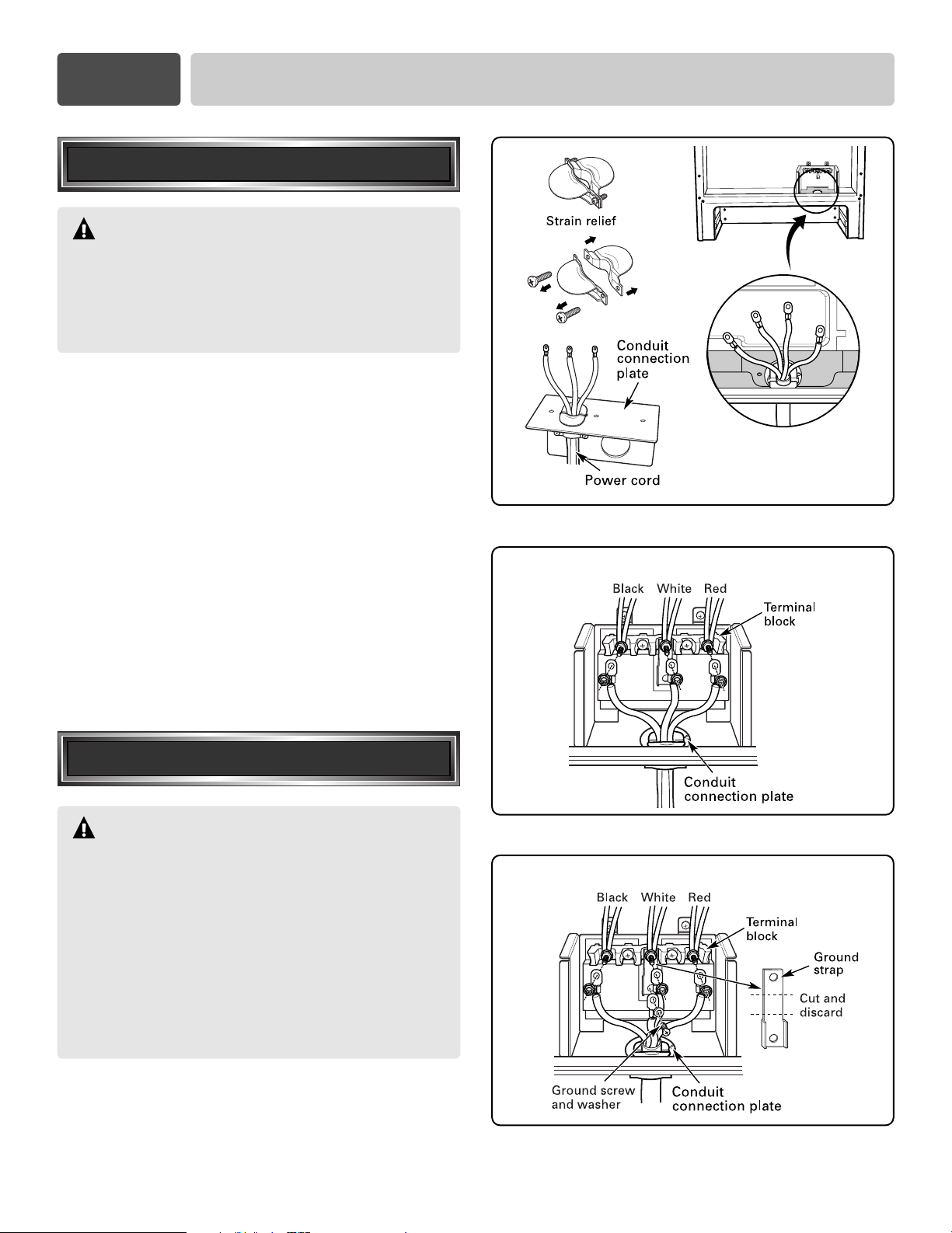
Install the power cord as follows:
For power cord installations, Hook the strain relief
over the power cord hole (13/8”) located below the rear
of drawer body. Insert the power cord through the
strain relief and tighten it. (Refer to Figure 5.)
You must install the power cord with a strain relief.
1. Remove the 3 nuts from the terminal block and
retain them. (Refer to Figure 6.)
2. Attach the 3 wires (L1, Neutral, L2) to each terminal
block bolt. Make sure that the center wire (neutral)
is connected to the center position of the terminal
block.
3. Tighten the 3 nuts securely into the terminal block.
Do not remove the ground strap connection.
4. Go to page 8.
Attach the strain relief
to the 13/8” opening in
Conduit connection plate
FIGURE 5
3-wire connection
4-wire connection with a power supply cord
WARNING
Only a 4-conductor power-supply cord kit rated
120/240 volts, 50 amperes and marked for use with
ranges with closed-loop connectors, open-end spade
lugs with upturned ends shall be used. The middle
(neutral) wire of the power cord or 4-wire conduit has
to be connected to the middle post of the main terminal
block. Other two wires of the power cord or conduit
have to be connected to the outside posts of the main
terminal connection block. The 4th ground wire must
be connected to the frame of the range with the ground
screw.
Follow the instructions under “Install the power cord
as follows” on page 5 to correctly install the strain
relief.
4-wire connection
5
L2L2
FIGURE 6
NN
L1L1
GG
FIGURE 7
Page 6

Part 3 ELECTRICAL CONNECTIONS
1.
Remove the 3 nuts from the terminal block.
(
Refer to
Remove the ground screw and washer retain them.
2. Cut the center portion of ground strap as
shown Figure 7.
Do not discard any screws.
3. Attach the ground wire with the ground screw and
washer.
4. Attach the 3 wires (L1, Neutral, L2) to the correct
terminal block bolts. Be certain that the center wire
(white/neutral) is connected to the center position of
the terminal block. Tighten the 3 nuts securely onto
the terminal block.
5. Go to page 8.
Figure 7.)
3-wire connection: conduit
Install the conduit as follows:
Remove the Conduit connection plate from the rear of
drawer body and rotate it as shown in Figure 8. The
conduit hole (11/8”) must be used.
First, prepare conduit cord as shown in Figure 9.
3 wire 4 wire
or
FIGURE 9
Second, install conduit cord as shown in Figure 10.
For conduit installations, after purchasing a strain
relief, insert it in the conduit hole (11/8”). Then install
the conduit cord through the body of strain relief and
fasten the strain relief with its ring. Reinstall the
bracket.
Remove the Conduit connection plate
FIGURE 8
Assemble the
strain relief hole
FIGURE 10
6
Page 7

Part 3 ELECTRICAL CONNECTIONS
L2
L1
N
Third, connect the wires.
If bare wire is used, connect with adapter lugs as shown
in Figures 11 and 12.
1. Insert the end of each wire (L1, L2, Neutral) into the
each lug. Tighten the clamping screw.
2. Remove the 3 nuts from the terminal block and
retain them.
3. Attach the lug with white wire (Neutral) to the center
terminal block bolt.
4. Attach the lug with black wire (L2) to the left
terminal block bolt.
5. Attach the lug with red wire (L1) to the right terminal
block bolt.
6. Tighten 3 nuts (removed earlier) securely onto the
terminal block.
7. Go to page 8.
Reinstall the
Conduit connection plate
BARE WIRE TORQUE SPECIFICATIONS
LUG ATTACHED TO TERMINAL BLOCK
- 20 IN-LB
WIRE AWG
10-14
8
4-6
FIGURE 11
TORQUE
20 IN-LB
25 IN-LB
35 IN-LB
4-wire connection: conduit
1. Follow the instructions under “Install the conduit
cord as follows” on page 6 to correctly install the
strain relief.
You must install the conduit with a strain
relief.
2. Cut the center portion of ground strap as
shown Figure 13.
Do not discard any screws.
If bare wire is used, connect with adapter lugs as
shown in Figures 11 and 13.
3. Insert the end of green wire (ground) from conduit
into the lug and tighten the clamping screw. Attach
the lug to the GND hole below terminal block with
ground screw (removed earlier).
4. Insert the end of each wire (L1, L2, Neutral) into
each separate lug. Tighten the clamping screw.
5. Remove the 3 nuts from the terminal block.
Remove the ground screw and retain them.
6. Attach the lug with white wire (Neutral) to the
center terminal block bolt.
7. Attach the lug with black wire (L2) to the left
terminal block bolt.
8. Attach the lug with red wire (L1) to the right
terminal block bolt.
9. Tighten 3 nuts (removed earlier) securely into the
terminal block.
10. Go to page 8.
3-wire connection
L2
L2
4-wire connection
L2
L2
GG
L1
L1
N
N
FIGURE 12
L1
L1
N
N
FIGURE 13
7
Page 8

Part 4 INSTALL THE RANGE
Replace the access cover on the range back. To
replace the wire cover, insert double projections in the
pockets located below the opening and tighten the
three screws.
ANTI-TIP DEVICE INSTALLATION
5
Use a spirit level to check your adjustments. Place the
level diagonally on the oven rack, and check each
direction for level.
First check direction 1
.
WARNING
• To reduce the risk of tipping, the appliance must be
secured by properly installed anti-tip devices packed
with the appliance.
• See instructions to install (supplied with bracket).
• Unless properly installed, the range could be tipped
by stepping or sitting on the door. Injury may result
from spilled hot liquids or from the range itself.
Note
To install Anti-tip bracket, release the leveling leg. A
minimum clearance of 0.65”(16.5mm) is required
between the range bottom and the kitchen floor.
1. Locate the bracket using the template
An Anti-tip bracket is packaged with template. The
instructions include necessary information to
complete the installation.
Read and follow range installation instruction sheet
(template).
2. Level the range
Level the range by adjusting the leveling legs with a
wrench.
After check direction 2.
If the spirit level doesn’t show
level on the rack, adjust the
leveling legs with a wrench.
6
FINAL INSTALLATION
• Move range close enough to the opening to plug
into the receptacle.
• Slide range into position insuring that the left back
leg slides under the anti-tip bracket. Range will sit 0”
away from the back wall when properly installed.
• Carefully tip range forward to insure that the anti-tip
bracket engages the range back brace and prevents
tip-over.
• Turn on electrical power. Check range for proper
operation as described in owner’s manual.
8
Page 9

Sitio Web: http://us.lge.com
Manual de instalación
Estufa eléctrica
LRE30451S / LRE30755S
Sírvase leer cuidadosamente estas instrucciones
antes de instalar y poner a funcionar la estufa.
Número de pieza : 3828W5U0512
Page 10

Sección 1
1
ANTES DE COMENZAR
Antes de usar la estufa, quite todas las cintas y materiales
de empaque. Después de desempacar la estufa deseche
todas las bolsas de plástico. Nunca permita que los niños
jueguen con los materiales de empaque.
SEGURIDAD
PREPARATIVOS PARA INSTALAR LA
ESTUFA
HERRAMIENTAS NECESARIAS
INSTRUCCIONES DE SEGURIDAD MUY
IMPORTANTES
ADVERTENCIA El no seguir exactamente las
instrucciones de este manual puede ocasionar
incendios o sacudidas eléctricas que podrían causar
daños a la propiedad, lesiones personales o la
muerte.
ADVERTENCIA
•
TODAS LAS ESTUFAS PUEDEN
VOLCARSE
•
ALGUNAS PERSONAS PODRÍAN
RESULTAR LESIONADAS
•
SE DEBE INSTALAR LA MÉNSULA
ANTI-VOLCADURAS PROVISTA
JUNTO CON LA ESTUFA.
•
CONSULTE LAS INSTRUCCIONES
DE INSTALACIÓN
Notas importantes para el instalador
• Antes de instalar la estufa lea todas las instrucciones
incluidas en estas instrucciones de instalación.
• Antes de conectar la fuente de alimentación
eléctrica debe quitar todos los materiales de
empaque del compartimiento del horno.
• Cumpla con todos los códigos y ordenanzas vigentes.
•
Siempre deje estas instrucciones con el consumidor.
Notas importantes para el consumidor
Conserve estas instrucciones junto con su manual del
propietario para cualquier consulta en el futuro.
• Al igual que cuando se utiliza cualquier artefacto que
genera calor, deben seguirse ciertas precauciones de
seguridad.
• Cerciórese de que su estufa sea instalada y conectada
a tierra correctamente por un instalador o técnico de
servicio calificado.
• Cerciórese de que todos los adornos o recubrimientos
de la pared que están alrededor de la estufa tienen
la capacidad de resistir el calor generado por la
misma.
• Se debe evitar el uso de gabinetes de
almacenamiento encima de la estufa para no tener
que alcanzarlos por encima de los elementos de
cocción.
Destornillador Phillips
Destornillador
de hoja plana
Llave de caja de 3/8”
Alicates
PIEZAS PROVISTAS
Plantilla
Manguitos de anclaje
(Solamente cuando se instala la ménsula
de anti-volcadura en pisos de concreto)
Juego de ménsula
anti-volcaduras
Pernos de fijación
PIEZAS NO PROVISTAS
(Aprobado por la UL
para 40 0 50 AMPS)
Cable de 4 alambres o de 3
alambres
Nivel
Llave de
tuercas ajustable
Taladro
Orejeta
(Para conexión
de conducto)
Tensor de alivio
(Solamente para
instalaciones con
conducto portacables)
2
Page 11

Sección 2
2
ILUSTRACIONES DE INSTALACIÓN
PREPARATIVOS PARA INSTALAR LA ESTUFA
IMPORTANTE
GUÁRDELO PARA EL USO DEL INSPECTOR LOCAL DE INSTALACIONES ELÉCTRICAS.
HOLGURAS Y DIMENSIONES (Figura 1)
Consulte la figura 1 a continuación para la instalación de la estufa.
Si se va a instalar en CANADÁ, una estufa autónoma no podrá instalarse a menos de 12 mm de cualquier
superficie adyacente.
PRECAUCIÓN
cumplir con las temperaturas máximas permitidas para
gabinetes de madera, es decir 194°F (90°C). Cerciórese de
que los recubrimientos de la pared, cubierta y gabinetes
alrededor de la estufa pueden resistir la temperatura
generada por la estufa (194°F (90°C)). De lo contrario podría
presentarse decoloración, derretimiento o delaminación.
Esta estufa ha sido diseñada para
IMPORTANTE
quemaduras o incendios cuando se trata de alcanzar algo
por encima de unidades con superficies calientes, debe
evitarse disponer de gabinetes de almacenamiento por
encima de las unidades de superficie. Si se han provisto
gabinetes de almacenamiento, puede reducirse el riesgo si
se instala una campana de estufa que sobresalga un mínimo
de 5 pulgadas (12 cm) de la parte inferior de los gabinetes.
Para eliminar los riesgos de
A = 30” (76.2 cm) Para EE.UU.
= 30” (76.2 cm) ~ 31” (78.7 cm) Para CANADÁ
FIGURA 1 FIGURA 2
DIMENSIONES MÍNIMAS (Figura 2)
* 30”(76.2 cm) de holgura mínima entre la cubierta de la superficie de cocción y la base de un gabinete de
madera o de metal sin protección; o 24”(60.9 cm) como mínimo cuando la parte inferior de un gabinete
de madera o de metal está protegida por una capa de 1/4”(6.4 mm) de cartón gris resistente al fuego y
recubierta cuando menos con lámina de acero no. 28 MSG , 0.015”(0.381 mm) de acero inoxidable,
0.024”(0.610 mm) de aluminio o 0.020”(0.508 mm) de cobre.
** 15” (38.1 cm) como mínimo entre la cubierta de los gabinetes y la parte inferior del gabinete adyacente.
3
Page 12

Sección 3
CONEXIONES ELÉCTRICAS
3
REQUISITOS DE LAS CONEXIONES
ELÉCTRICAS
Este artefacto deberá instalarse y conectarse a tierra
en un circuito de red por un técnico certificado, de
acuerdo con la edición más reciente del código de la
National Electrical code ANSI/NFPA NO. 70
Todo el alambrado deberá conformarse a Local y NEC.
Esta estufa requiere de un sistema eléctrico monofásico,
de 3 alambres, 120/208 V C.A. o 120/240 V 60Hz. Use
solamente un cable de 3 o 4 alambres para estufa
reconocido por la UL, con terminales de ojillo cerrado,
lengüetas de pala con extremos doblados o terminales
parecidas. El cable deberá tener un tensor de alivio
montado correctamente.
Es necesario un cable para estufa con capacidad
nominal de 120/240 V a 40 amps. Si se llegara a usar
un cable de estufa de 50 amps., deberá estar marcado
como para ser utilizado en aberturas de conexión de
13.8” (3.5 cm) de diámetro.
Este artefacto puede conectarse usando un conductor
de cable o cable de alimentación. Si se utilizan
conductos portacables, consulte la página 6.
Conexiones de conductos portacables con 3 alambres
o la página 7 para las conexiones de conductos
portacables con 4 conductores.
3, Tipos de tomacorriente de pared de 4 alambres.
Tomacorriente de
4 alambres (14-50R)
Tomacorriente de
3 alambres (10-50R)
FIGURA 3
Para la instalación del cable de alimentación o de
conducto portacables se deben usar placas de
conexión para conectar a conductos portacables. El
cable de alimentación deberá instalarse con la placa
de conexión de conductos portacables provista por el
fabricante. En el caso de conductos portacables, quite
la placa de conexión de conductos portacables que
está ubicada debajo de la parte posterior del cuerpo
del cajón y use el orificio del conducto portacables
(11/8” (2.8 cm)) en lugar del orificio del cable de
alimentación (13/8” (3.5 cm)).
(Consulte la Figura 8.)
ADVERTENCIA
Todas las instalaciones de red nuevas (1996 NEC),
remolques, vehículos recreativos e instalaciones
donde los códigos locales no permiten la conexión
a tierra por el neutro requieren un cable de 4
alambres reconocido por la UL o conexión a
conductos portacables de 4 alambres.
4
CÓMO CONECTAR EL CABLE DE LA
ESTUFA
Debe quitarse la cubierta de acceso posterior. Use un
destornillador para aflojar los tres tornillos. Entonces
se podrá tener acceso a un bloque de terminales.
FIGURA 4
Clasificación nominal especificada para el
juego del cable de alimentación
Capacidad nominal de la
estufa. Vatios
120/240 voltios
3 alambres
8,750 - 16,500
16,501 - 22,500
120/208 voltios
3 alambres
7,801 - 12,500
12,501 - 18,500
Clasificación
nominal
especificada para
el juego de cable
de alimentación,
amperios
40 o 50A
50
Diámetro (en pulgadas) de la
abertura de conexión de la estufa
Cable de
alimentación
13/8”
13/8”
Conducto
portacables
1
1
/8”
11/8”
4
Page 13

Sección 3
CONEXIONES ELÉCTRICAS
Conexión de 3 alambres
con un cable de alimentación
ADVERTENCIA
El cable central (neutro o tierra) del cable de
alimentación o conducto portacables de 3 alambres
debe conectarse al poste central del bloque de
terminales principal. Los dos alambres restantes del
cable de alimentación o conducto portacables de 3
alambres deberán conectarse a los postes externos
del bloque de terminales principal.
Instale el cable de alimentación como sigue:
Para las instalaciones del cable de alimentación,
enganche el tensor de alivio al orificio del cable de
alimentación (13/8” (3.5 cm)) ubicado debajo de la
parte posterior del cuerpo del cajón. Inserte el cable
de alimentación a través del tensor de alivio y
apriételo. (Consulte la Figura 5.)
Afiance el tensor de alivio
Al orificio de
placa del conducto portacables
FIGURA 5
3
/8”
1
(3.5 cm) en la
El cable de alimentación deberá instalarse con un
tensor de alivio.
1. Quite las 3 tuercas del bloque de terminales y
guárdelas. (Consulte la Figura 6.)
2. Afiance los 3 alambres (L1, Neutral, L2) a cada
perno del bloque de terminales. Cerciórese de que
el alambre central (neutral) se conecta al poste
central del bloque de terminales.
3.
Apriete las 3 tuercas firmemente al bloque de terminales.
No quite la conexión de la cinta de conexión a tierra.
4. Diríjase a la página 8.
Conexión de 4 alambres
con un cable de alimentación
ADVERTENCIA
Use solamente un cable de alimentación de 4 alambres
con capacidad nominal de 120/240 voltios, 50 amperios y
marcado para ser utilizado en una estufa, con terminales
de ojillo cerrado o lengüetas de pala con extremos doblados.
El cable central (neutro o tierra) del cable de alimentación
o conducto portacables de 4 alambres debe
poste central del bloque de terminales principal.
alambres restantes del cable de alimentación o conducto
portacables deberán conectarse a los postes externos del
bloque de terminales principal. El 4˚ alambre de tierra deberá
conectarse al marco de la estufa usando el tornillo de tierra.
conectarse al
Los dos
Conexión de 3 alambres
FIGURA 6
Conexión de 4 alambres
Para instalar correctamente el tensor de alivio, siga
las instrucciones “Instale el cable de alimentación
como sigue” en la página 5.
FIGURA 7
5
Page 14

Sección 3
1.
Quite las 3 tuercas del bloque de terminales .
(Consulte la Figura 7.)
Quite el tornillo de tierra y la arandela y guárdelos.
2. Corte la parte central de la cinta de tierra
como se muestra en la figura 7.
No deseche los tornillos.
3. Afiance el alambre de tierra con el tronillo de tierra
y la arandela.
4. Afiance los 3 alambres (L1, Neutral, L2) al perno del
bloque de terminales correspondiente. Cerciórese
de que el alambre central (blanco / neutral) se
conecta al poste central del bloque de terminales.
Apriete las 3 tuercas firmemente al bloque de
terminales.
5. Diríjase a la página 8.
CONEXIONES ELÉCTRICAS
Conexión de 3 alambres
conducto portacables
Instale el conducto portacables de la
manera siguiente:
Quite la placa de conexión de conductos portacables
de la parte posterior del cuerpo del cajón y déle vuelta
como se muestra en la figura 8. Debe usarse el orificio
de conducto portacables (11/8” (3 cm)).
Primero prepare el cable del conducto portacables tal
como se muestra en la figura 9.
3 alambres 4 alambres
or
FIGURA 9
Seguidamente instale el cable del conducto
portacables tal como se muestra en la figura 10.
Para las instalaciones de conducto portacables,
compre un tensor de alivio e insértelo en el orificio del
conducto portacables (11/8” (2.9 cm)) Luego instale el
cable del conducto portacables por el cuerpo del
tensor de alivio y afiance el tensor de alivio usando su
anillo. Vuelva a instalar la ménsula.
Quite la placa de conexión
de conductos portacables
FIGURA 8
Ensamble el orificio
del tensor de alivio
FIGURA 10
6
Page 15

Sección 3
L2
L1
N
CONEXIONES ELÉCTRICAS
En tercer lugar conecte los alambres.
Si usa alambre desnudo, conecte con adaptadores de
orejetas, como se muestra en las Figuras 11 y 12.
1. Inserte el extremo de cada alambre (L1, L2, Neutral)
en cada orejeta. Apriete los tornillos de apriete.
2. Quite las 3 tuercas del bloque de terminales y
guárdelas.
3. Afiance la orejeta con el alambre blanco (Neutral) al
perno central del bloque de terminales.
4. Afiance la orejeta con el alambre negro (L2) al perno
izquierdo del bloque de terminales.
5. Afiance la orejeta con el alambre rojo (L1) al perno
derecho del bloque de terminales.
6. Apriete firmemente las 3 tuercas (que retiró
anteriormente) al bloque de terminales.
7. Diríjase a la página 8.
Vuelva a instalar la placa de conexión para
conectar a conductos portacables
ESPECIFICACIONES DEL PAR DE
TORSIÓN DEL ALAMBRE DESNUDO
OREJETA AFIANZADA AL BLOQUE DE
TERMINALES - 20 IN-LB
ALAMBRE CALIBRE AWG
10-14
8
4-6
PAR DE TORSIÓN
20 IN-LB
25 IN-LB
35 IN-LB
FIGURA 11
Conexión de 4 alambres
conducto portacables
1. Para instalar correctamente el tensor de alivio, siga
las instrucciones “Instale el cable de alimentación
como sigue” en la página 6.
El conducto portacables deberá instalarse con
un tensor de alivio.
2. Corte la parte central de la cinta de tierra
como se muestra en la figura 13.
No deseche los tornillos.
Si usa alambre desnudo, conecte con adaptadores
de orejetas, como se muestra en las Figuras 11 y 13.
3. Inserte el extremo del alambre verde (tierra) del
conducto portacables en la orejeta y apriete el
tornillo de apriete. Afiance la orejeta al orificio
GND debajo del bloque de terminales con el tornillo
de tierra (que retiró anteriormente).
4.
Inserte el extremo de cada alambre (L1, L2, Neutral) en
cada orejeta separada. Apriete el tornillo de apriete.
5. Quita las 3 tuercas del bloque de terminales
Quite el tornillo de tierra y guárdelo.
6. Afiance la orejeta con el alambre blanco (Neutral) al
perno central del bloque de terminales.
7. Afiance la orejeta con el alambre negro (L2) al
perno izquierdo del bloque de terminales.
8. Afiance la orejeta con el alambre rojo (L1) al perno
derecho del bloque de terminales.
9. Apriete las 3 tuercas (que retiró anteriormente)
firmemente al bloque de terminales.
10. Diríjase a la página 8.
Conexión de 3 alambres
L2
FIGURA 12
L1
N
Conexión de 4 alambres
L2
L1
N
G
FIGURA 13
7
Page 16

Sección 4
Reponga la cubierta de acceso en la parte posterior de
la estufa. Para reponer la cubierta de alambre, inserte
las salientes dobles en las cavidades ubicadas debajo
de la abertura y apriete los tres tornillos.
INSTALACIÓN DEL DISPOSITIVO
5
CÓMO INSTALAR LA ESTUFA
ANTI-VOLCADURAS
Utilice un nivel de burbuja para verificar sus ajustes.
Coloque el nivel en la parrilla del horno de la estufa en
forma diagonal y verifique el nivel en cada dirección.
Primero verifique la dirección 1
.
ADVERTENCIA
• Con el fin de reducir el riesgo de volcaduras, el
artefacto deberá asegurarse usando los dispositivos
anti-volcaduras provistos junto con el artefacto.
• Consulte las instrucciones para la instalación
(provistas con la ménsula).
• Si no se instaló correctamente, la estufa podría
volcarse si se pisa o se sienta en la puerta. Podrían
producirse lesiones por el derrame de líquidos
calientes o por la estufa misma.
Nota
Para la instalación de la ménsula anti-volcaduras,
libere la pata niveladora. Se necesita una holgura de
0.65” (16.5 mm) entre el fondo de la estufa y el piso
de la cocina.
Después verifique la dirección 2.
Si el nivel de burbuja no
muestra que la parrilla está
nivelada, ajuste las patas
niveladoras con una llave de tuercas.
INSTALACIÓN FINAL
6
• Acerque la estufa lo suficiente a la abertura para
poder enchufarla en el tomacorriente.
• Acomode la estufa en su puesto cerciorándose de
que la pata posterior izquierda se desliza debajo de
la ménsula anti-volcaduras. Una vez que esté
instalada correctamente, la estufa quedará a 0” de
distancia de la pared trasera.
• Con cuidado, incline la estufa hacia adelante para
comprobar que la ménsula anti-volcaduras
engancha con el tirante posterior de la estufa e
impide que la estufa se vuelque.
• Encienda la alimentación de energía eléctrica.
Verifique que la estufa está orientada correctamente
tal como se describe en el manual del propietario.
1. Ubique la ménsula utilizando la plantilla.
La plantilla viene empacada con cada ménsula antivolcaduras. Las instrucciones incluyen la
información necesaria para llevar a buen término la
instalación.
Lea y obedezca el contenido de la hoja de
instrucciones (plantilla) de la estufa.
2. Nivele la estufa
Nivele la estufa ajustando las patas niveladoras con
una llave de tuercas.
8
 Loading...