

Page 1
CAUTION
BEFORE SERVICING THE UNIT,
READ THE SAFETY PRECAUTIONS IN THIS MANUAL.
REFRIGERATOR
SERVICE MANUAL
MODEL:
LRDC22734**
LRDN22712**
LRDN20724**
LRDC22744**
Page 2

CONTENTS
DESCRIPTION OF FUNCTION & CICUIT OF MICOM (GOOD, BETTER) ..................................................................... 45-64
REFRIGERATOR EXPLODED VIEW & SERVICE PARTS LIST.......................................................................................65-102
SAFETY PRECAUTIONS ....................................................................................................................................................... 2
SPECIFICATIONS................................................................................................................................................................... 3
PARTS IDENTIFICATION.................................................................................................................................................... 4-7
DISASSEMBLY.................................................................................................................................................................... 8-9
DOOR................................................................................................................................................................................... 8
DOOR SWITCH.................................................................................................................................................................... 8
FAN AND FAN MOTOR........................................................................................................................................................ 9
DEFROST CONTROL ASSEMBLY...................................................................................................................................... 9
LAMP.................................................................................................................................................................................... 9
CONTROL BOX-REFRIGERATOR...................................................................................................................................... 9
MULTI DUCT ........................................................................................................................................................................ 9
ADJUSTMENT.................................................................................................................................................................. 10-11
COMPRESSOR.................................................................................................................................................................. 10
PTC-STARTER.................................................................................................................................................................. 10
OLP (OVERLOAD PROTECTOR)....................................................................................................................................... 11
TO REMOVE THE COVER PTC..........................................................................................................................................11
CIRCUIT DIAGRAM.......................................................................................................................................................... 12-13
TROUBLESHOOTING...................................................................................................................................................... 14-19
COMPRESSOR AND ELECTRIC COMPONENTS ........................................................................................................... 14
PTC AND OLP.................................................................................................................................................................... 15
OTHER ELECTRICAL COMPONENTS............................................................................................................................. 16
SERVICE DIAGNOSIS CHART.......................................................................................................................................... 17
REFRIGERATION CYCLE ............................................................................................................................................ 18-19
OPERATION PRINCIPLE & REPAIR METHOD OF ICEMAKER .................................................................................. 20-23
DESCRIPTION OF FUNCTION & CIRCUIT OF MICOM (BEST, DISPENSER) ............................................................. 24-44
SAFETY PRECAUTIONS
Please read the following instructions before servicing your
refrigerator.
1. Check the refrigerator for electrical faults.
2. To prevent electric shock, unplug before servicing.
3. Always check line voltage and amperage.
4. Use standard electrical components.
5. Don't touch metal products in the freezer with wet
hands. This may cause frostbite or cause your skin to
freeze and stick to the surfaces inside the freezer.
6. Prevent water from flowing onto electric elements in the
mechanical parts.
7. Close the top door before opening the bottom door.
Otherwise, you might hit your head when you stand up.
8. When tilting the refrigerator, remove any materials on
the refrigerator, especially the glass shelves and stored
foods.
9. When servicing the evaporator, wear cotton gloves.
This is to prevent injuries from the sharp evaporator
fins.
10. Disassembly, repair, and servicing the sealed
refrigeration system should be performed only by
qualified and certified personnel. Refrigerant should
not be vented into the atmosphere; proper recovery
equipment should be used.
- 2 -
Page 3
1. SPECIFICATIONS
20 cu. ft. / 22 cu. ft.
ITEMS SPECIFICATIONS
DOOR DESIGN Side Rounded
3
29 7/
8 X 31
DIMENSIONS (inches)
NET WEIGHT (pounds)
COOLING SYSTEM Fan Cooling
TEMPERATURE CONTROL Micom Control
DEFROSTING SYSTEM
DOOR FINISH Embossed Metal, VCM, Stainless
HANDLE TYPE Bar, Al
INNER CASE ABS Resin
INSULATION Polyurethane Foam
32 7/8 X 31 3/4 X 69 1/2 (WX
32 7/8 X 31 3/4 X 68 1/2 (WX
238.4 (
246.9 (
Full Automatic
Heater Defrost
/
4 X 67
20cu.ft)
22cu.ft)
7
/
8 (WXDXH) 20cu.ft
DXH) 22cu.ft Dispenser
DXH) 22cu.ft
ITEMS SPECIFICATIONS
VEGETABLE TRAY Opaque Drawer Type
COMPRESSOR PTC Starting Type
EVAPORATOR Fin Tube Type
CONDENSER Wire Condenser
REFRIGERANT R-134a (115 g)
LUBRICATING OIL Freol @ 10G (310 cc)
DEFROSTING DEVICE SHEATH HEATER
REFRIGERATOR 60 W (2EA)
LAMP
FREEZER 60 W (2EA)
- 3 -
Page 4
2. PARTS IDENTIFICATION
- 4 -
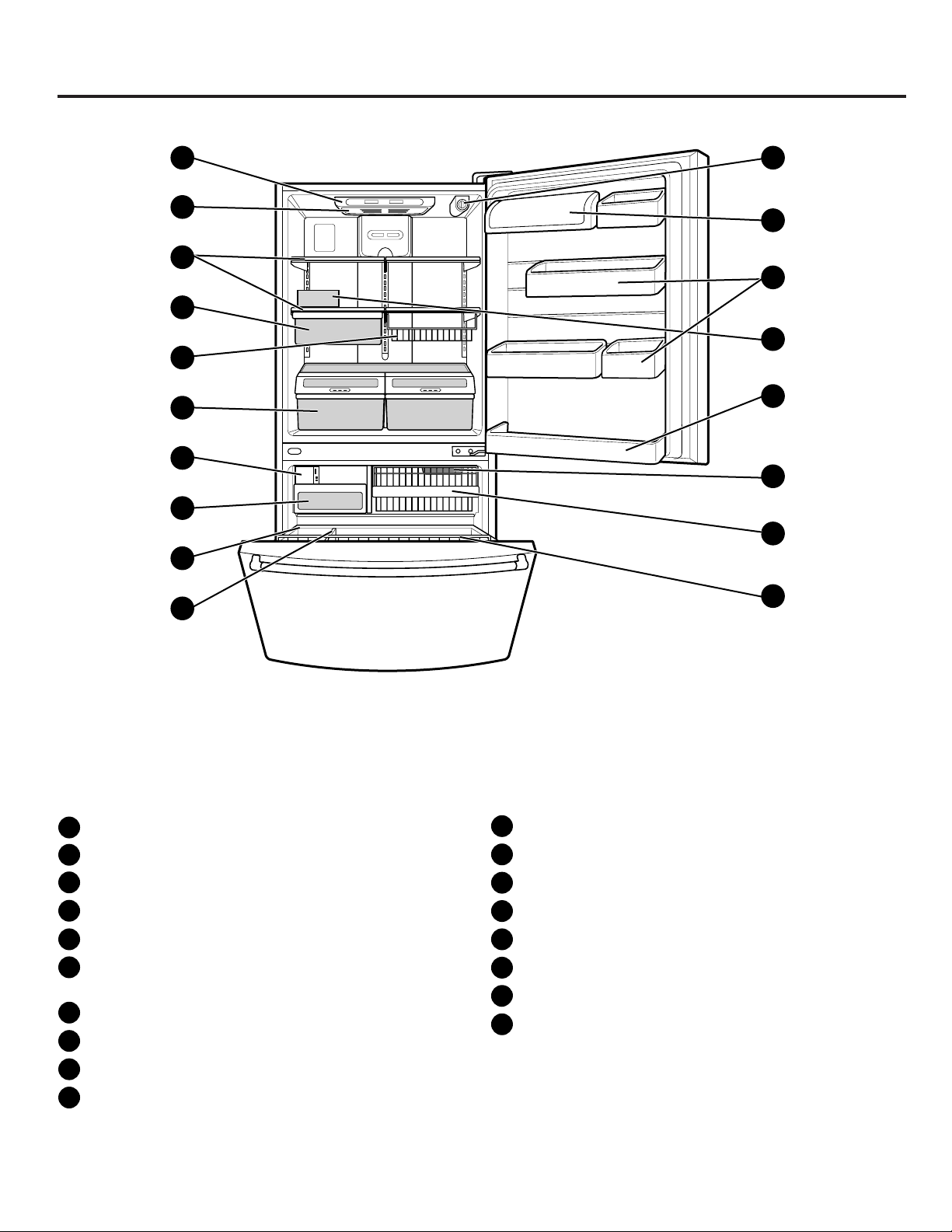
PARTS AND FEATURES
A
B
C
D
E
F
G
H
J
K
L
M
N
O
P
Q
I
R
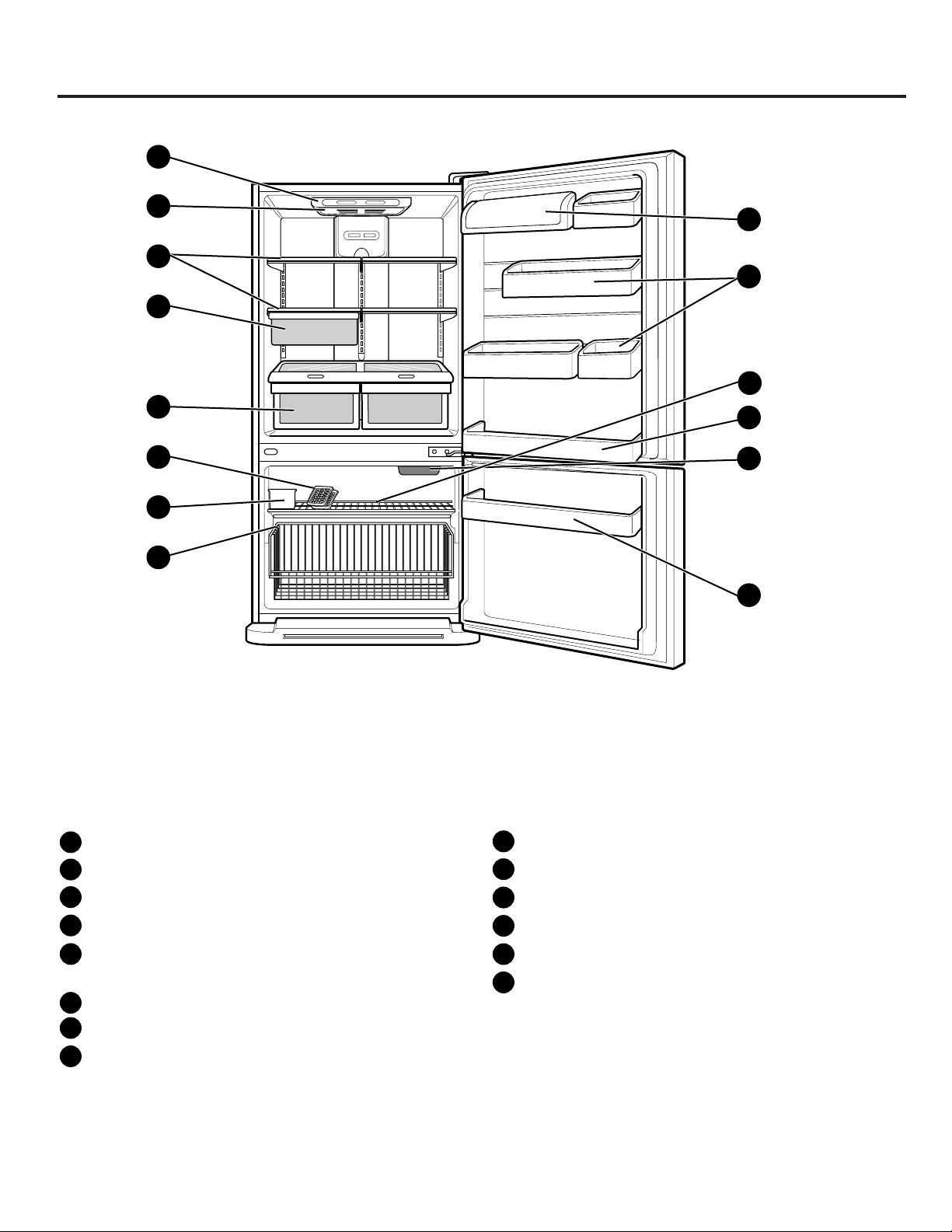
NOTE:This guide covers several different models.The refrigerator you have purchased may have some
or all of the items listed below. The locations of the features shown below may not match your model.
A
Digital Sensor Control
B
Refrigerator Light
C
Shelves
D
Chef Fresh / Snack Pan*
E
Can Dispenser*
F
Optibin Crisper
Keeps fruits and vegetable fresh and crisper
G
Customcube Icemaker
H
Ice Bin
I
Durabase
J
Divider
K
Filter (inside)*
L
Dairy Bin
M
Design-A-Door
N
Egg Box
O
Refrigerator Door Rack
Freezer Light
P
Wire Basket
Q
Freezer Door Rack (Tilting*)
R
*on some models
Page 5

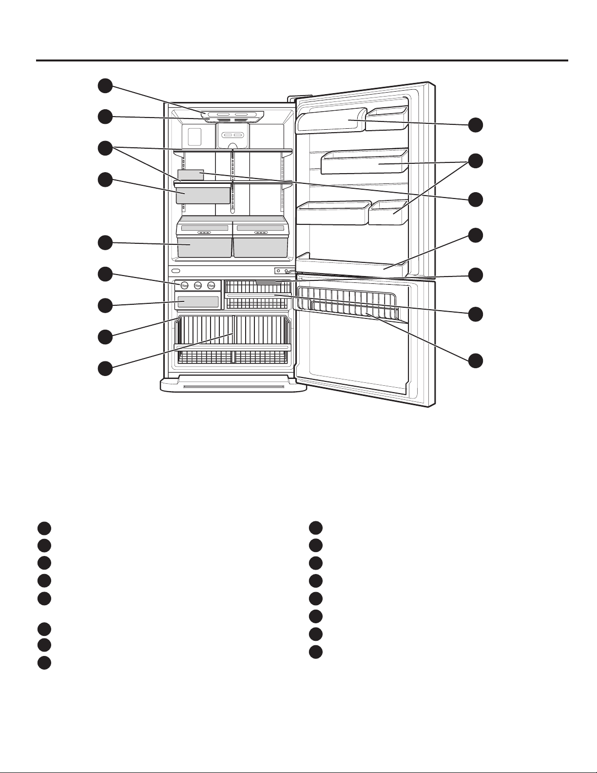
PARTS AND FEATURES
- 5 -
A
B
C
D
E
F
G
H
J
K
L
M
N
O
P
Q
I
R
NOTE:This guide covers several different models.The refrigerator you have purchased may have some
or all of the items listed below. The locations of the features shown below may not match your model.
A
Digital Sensor Control
B
Refrigerator Light
C
Shelves
D
Chef Fresh / Snack Pan*
E
Can Dispenser*
F
Optibin Crisper
Keeps fruits and vegetable fresh and crisper
G
Triple Ice Tray
H
Ice Bin
I
Durabase
J
Divider
K
Filter (inside)*
L
Dairy Bin
M
Design-A-Door
N
Egg Box
O
Refrigerator Door Rack
Freezer Light
P
Wire Basket
Q
Freezer Door Rack (Tilting*)
R
*on some models
Page 6
PARTS AND FEATURES
- 6 -
A
B
C
D
E
F
G
H
J
K
L
M
N
O
I
P
NOTE:This guide covers several different models.The refrigerator you have purchased may have some
or all of the items listed below. The locations of the features shown below may not match your model.
I
Divider
J
Dairy Bin
K
Design-A-Door
L
Egg Box
Refrigerator Door Rack
M
Freezer Light
N
Wire Basket
O
Freezer Wire Door Rack
P
Digital Sensor Control
A
B
Refrigerator Light
C
Shelves
D
Snack Pan
E
Optibin Crisper
Keeps fruits and vegetable fresh and crisp
Triple Twist Ice Tray
F
G
Ice Bin
H
Wire Durabase
Page 7
PARTS AND FEATURES
- 7 -
A
B
C
D
E
F
G
H
I
J
K
L
M
N
NOTE:This guide covers several different models.The refrigerator you have purchased may have some
or all of the items listed below. The locations of the features shown below may not match your model.
I
Dairy Bin
J
Design-A-Door
K
Wire Freezer Shelf
L
Refrigerator Door Rack
Freezer Light
M
Freezer Door Rack
N
Digital Sensor Control
A
B
Refrigerator Light
C
Shelves
D
Snack Pan
E
Optibin Crisper
Keeps fruits and vegetable fresh and crisp
Ice Trays
F
G
Ice Bin
H
Wire Durabase
Page 8
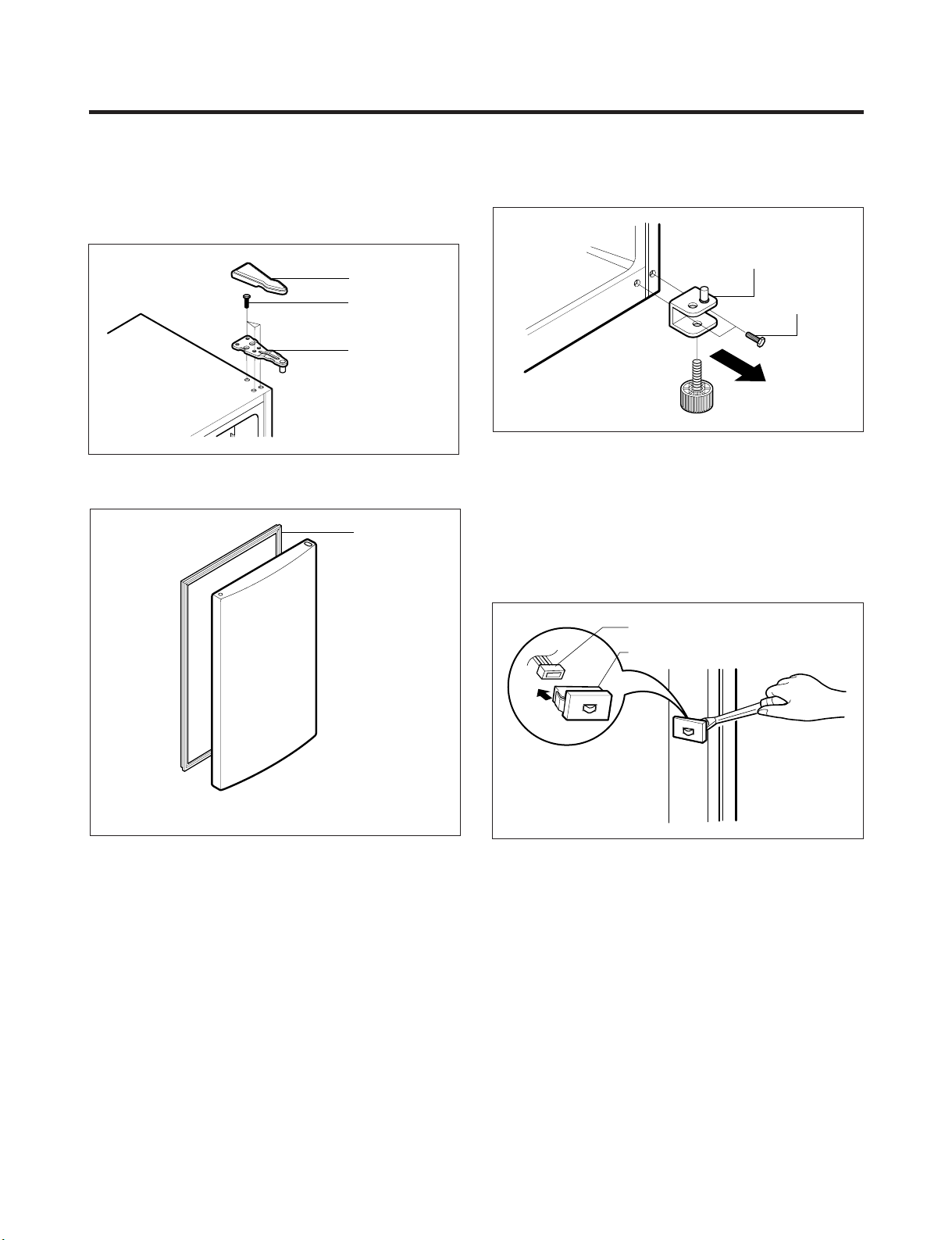
3. DISASSEMBLY
BOLT
HINGE
HINGE COVER
GASKET
LOWER HINGE
BOLT
DOOR SWITCH
LEAD WIRE
3-1 DOOR
● Refrigerator Door
1. Remove the hinge cover by pulling it upwards.
2. Loosen the hexagonal bolts attaching the upper hinge to
the body and lift the freezer door.
Figure 1
3. Pull out the door gasket to remove from the door foam
assembly.
● Freezer Door
1. Loosen the hexagonal bolts attaching the lower hinge to
the body to remove the refrigerator door only.
Figure 3
2. Pull out the door gasket to remove from the door foam
assembly.
3-2 DOOR SWITCH
1. To remove the door switch, pry it out with a slotted-type
driver, as shown in (Figure 4).
2. Disconnect the lead wire from the switch.
Figure 2
Figure 4
- 8 -
Page 9
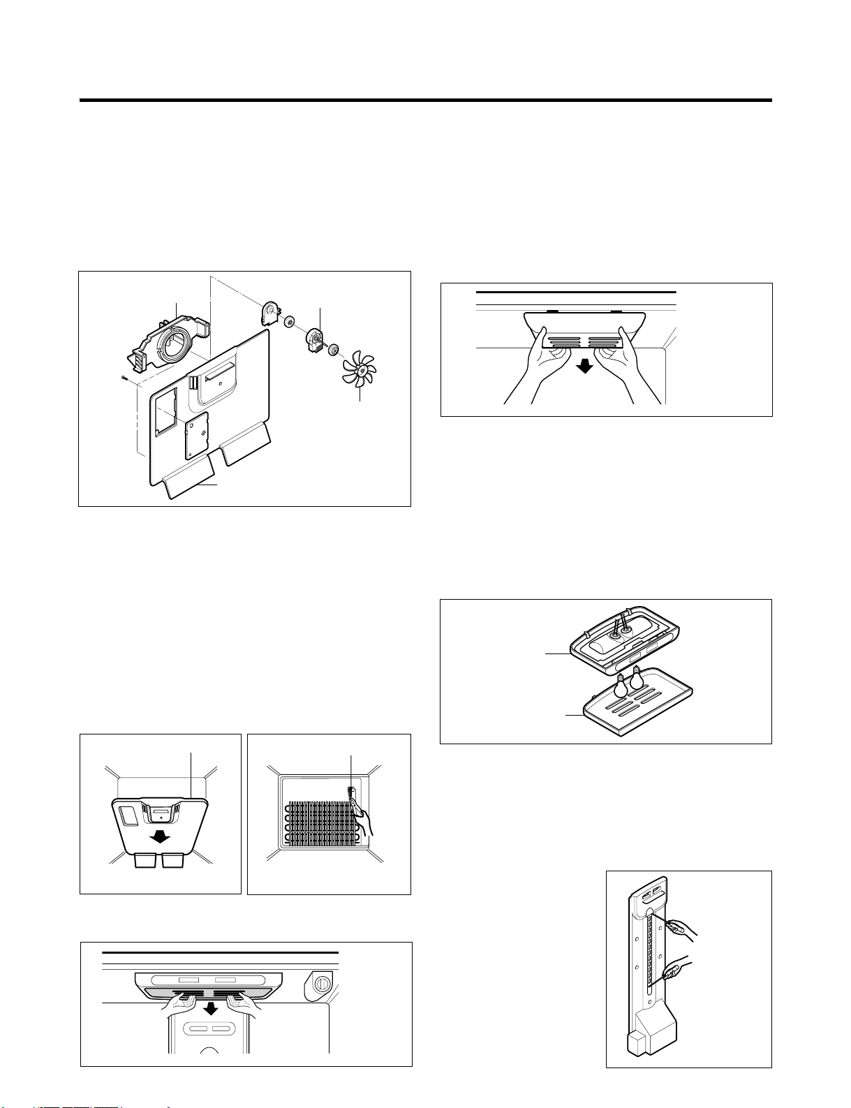
3-3 FAN AND FAN MOTOR
FAN
BRACKET
MOTOR
GRILLE
FAN MOTOR
GRILLE ASSEMBLY
DEFROST-CONTROL
ASSEMBLY
CONTROL BOX
COVER LAMP
1. Remove the freezer shelf. (If your refrigerator has an
icemaker, remove the icemaker first)
2. Remove the grille by pulling it out and by loosening a
screw.
3. Remove the Fan Motor assembly by loosening 2 screws
and disassemble the shroud.
4. Pull out the fan and separate the Fan Motor and Bracket.
Figure 5
3-4 DEFROST CONTROL ASSEMBLY
Defrost Control assembly consists of Defrost Sensor and
FUSE–M.
The Defrost Sensor works to defrost automatically. It is
attached to the metal side of the Evaporator and senses its
temperature. At 72°C, it turns the Defrost Heater off.
Fuse-M is a safety device for preventing over-heating of
the Heater when defrosting.
1. Pull out the grille assembly. (Figure 6)
2. Separate the connector with the Defrost Control
assembly and replace the Defrost Control assembly
after cutting the Tie Wrap. (Figure 7)
3-5-1 Refrigerator Compartment Lamp
1. Unplug the power cord from the outlet.
2. Remove refrigerator shelves.
3. Release the hooks on both ends of the lamp shield and
pull the shield downward to remove it.
4. Turn the lamp counterclockwise.
5. Assemble in reverse order of disassembly. Replacement
bulb must be the same specification as the original
(Max. 60 W-2EA).
Figure 9
3-5-2 Freezer Compartment Lamp
1. Unplug refrigerator or disconnect power.
2. Reach behind light shield to remove bulb.
3. Replace bulb with a 60-watt appliance bulb.
4. Plug in refrigerator or reconnect power.
3-6 CONTROL BOX-REFRIGERATOR
1. First, remove all shelves in the refrigerator, than remove
the Refrigerator control Box by loosening 2 screws.
Figure 10
3-5 LAMP
Figure 6
Figure 7
Figure 8
2. Remove the Refrigerator Control Box by pulling it
downward.
3. Disconnect the lead wire on the right position and
separate the lamp sockets.
3-7 MULTI DUCT
1. Remove an upper and
lower Cap by using a flat
screwdriver, and loosen 3
screws. (Figure 11)
2. Disconnect the lead wire
on the bottom position.
Figure 11
- 9 -
Page 10
4. ADJUSTMENT
PTC STARTER
SEALED
TERMINAL
COMPRESSOR
MOTOR
C
M
S
M
3
6
5
2
S
PTC
N
L1
OVERLOAD PROTECTOR
Resistance Starter Capacitor Running
4-1 COMPRESSOR
4-1-1 Role
The compressor intakes low temperature and low pressure
gas from the evaporator of the refrigerator and compresses
this gas to high-temperature and high-pressure gas. It then
delivers the gas to the condenser.
4-1-2 Composition
The compressor includes overload protection. The PTC
starter and OLP (overload protector) are attached to the
outside of the compressor. Since the compressor is
manufactured to tolerances of 1 micron and is hermetically
sealed in a dust and moisture-free environment, use
extreme caution when repairing it.
4-1-3 Note for Usage
(1) Be careful not to allow over-voltage and over-current.
(2) If compressor is dropped or handled carelessly, poor
operation and noise may result.
(3) Use proper electric components appropriate to the
Particular Compressor in your product.
(4) Keep Compressor dry.
If the Compressor gets wet (in the rain or a damp
environment) and rust forms in the pin of the Hermetic
Terminal, poor operation and contact may result.
(5) When replacing the Compressor, be careful that dust,
humidity, and soldering flux don’t contaminate the inside
of the compressor. Dust, humidity, and solder flux
contaminate the cylinder and may cause noise,
improper operation or even cause it to lock up.
4-2 PTC-STARTER
4-2-1 Composition of PTC-Starter
(1) PTC (Positive Temperature Coefficient) is a no-contact
semiconductor starting device which uses ceramic
material consisting of BaTiO
(2) The higher the temperature is, the higher the resistance
value. These features are used as a starting device for
the Motor.
4-2-2 Role of PTC-Starter
(1) The PTC is attached to the Sealed Compressor and is
used for starting the Motor.
(2) The compressor is a single-phase induction motor.
Durign the starting operation, the PTC allows current
flow to both the start winding and main winding.
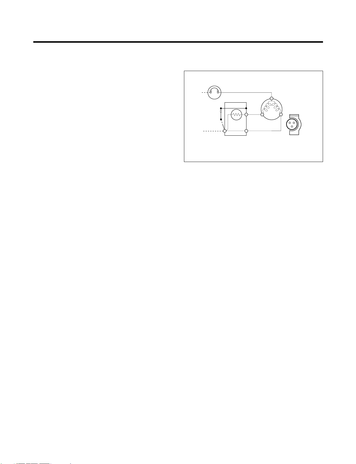
4-2-3 PTC-Applied Circuit Diagram
● Starting Method for the Motor
Figure 12
4-2-4 Motor Restarting and PTC Cooling
(1) It requires approximately 5 minutes for the pressure to
equalize before the compressor can restart.
(2) The PTC device generates heat during operation.
Therefore, it must be allowed to cool before the
compressor can restart.
4-2-5 Relation of PTC-Starter and OLP
(1) If the compressor attempts to restart before the PTC
device is cooled, the PTC device will allow current to
flow only to the main winding.
(2) The OLP will open because of the over current
condition. This same process will continue (3 to 5
times) when the compressor attempts to restart until
the PTC device has cooled. The correct OLP must be
properly attached to prevent damage to the
compressor.
Parts may appear physically identical but could have
different electrical ratings. Replace parts by part
3.
number and model number. Using an incorrect part
could result in damage to the product, fire, injury, or
possibly death.
4-2-6 Note for Using the PTC-Starter
(1) Be careful not to allow over-voltage and over-current.
(2) Do not drop or handle carelessly.
(3) Keep away from any liquid.
If liquid such as oil or water enters the PTC,
PTC materials may fail due to breakdown of their
insulating capabilities.
(4) If the exterior of the PTC is damaged, the resistance
value may be altered. This can cause damage to the
compressor and result in a no-start or hard-to-start
condition.
(5) Always use the PTC designed for the compressor and
make sure it is properly attached to the compressor.
Parts may appear physically identical but could have
different electrical ratings. Replace parts by part
number and model number. Using an incorrect part
could result in damage to the product, fire, injury, or
possibly death.
- 10 -
Page 11
4-3 OLP (OVERLOAD PROTECTOR)
Part
Customer part
number
Lot code/
date code
330 FBYY -S1 BOX98
12345678
Physical
termination
part number
Electrical
characteristics
part number
No. Name
Base, phenolic
(UL 94 V-0 rated)
Movable arm support, plated steel
Stationary contact support,
plated steel
Heater support, plated steel
Heater, resistance alloy
Disc, thermostatic alloy
Movable arm, spring temper
copper alloy
Contact, movable, silver on copper
Contact, stationary, silver on copper
Slug, plated steel
Cover, polyester
(UL 94 V -0 rated)
Pin connector, plated copper alloy
(To engage 2.33/2.66 mm dia. pin)
Quick-connect terminal, brass,
conforms to UL 310, MEMA
DC-2, DIN 46344
(OVERLOAD PROTECTOR cross section)
1
2
4-3-1 Definition of OLP
(1) OLP (OVERLOAD PROTECTOR) is attached to the
Compressor and protects the Motor by opening the
circuit to the Motor if the temperature rises and
activating the bimetal spring in the OLP.
(2) When high current flows to the Compressor motor, the
Bimetal works by heating the heater inside the OLP,
and the OLP protects the Motor by cutting off the
current flowing to the Compressor Motor.
4-3-2 Role of the OLP
(1) The OLP is attached to the Sealed Compressor used
for the Refrigerator. It prevents the Motor Coil from
being started in the Compressor.
(2) For normal operation of the OLP, do not turn the Adjust
Screw of the OLP in any way.
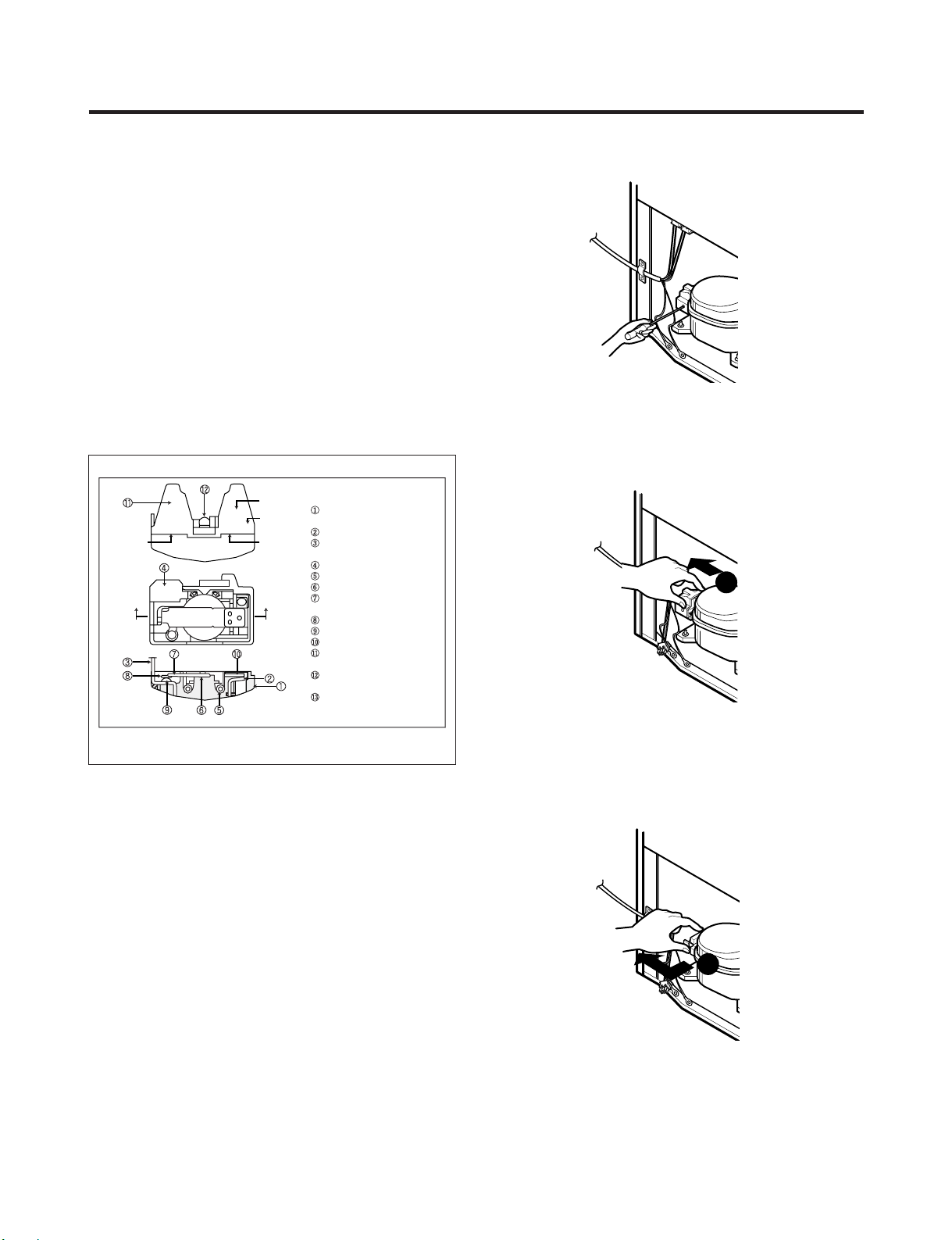
4-4 TO REMOVE THE COVER PTC
1) Remove the Cover Back M/C.
(2) Remove the screw on Cover PTC.
Figure 13
(3) Remove two Housings on upper part of Cover PTC.
(4) Take out the cover PTC from upper to lower position
like .
(5) Turn 45° in the direction of and take it out.
(6) Assembly in reverse order of disassembly.
- 11 -
Page 12
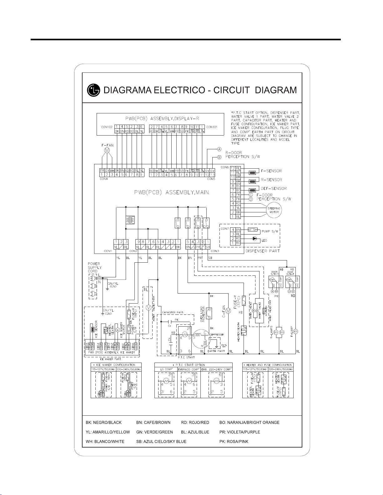
5. CIRCUIT DIAGRAM
5. CIRCUIT DIAGRAM
- 12 -
Best / Best dispenser
GY: GRIS/GRAY
Page 13
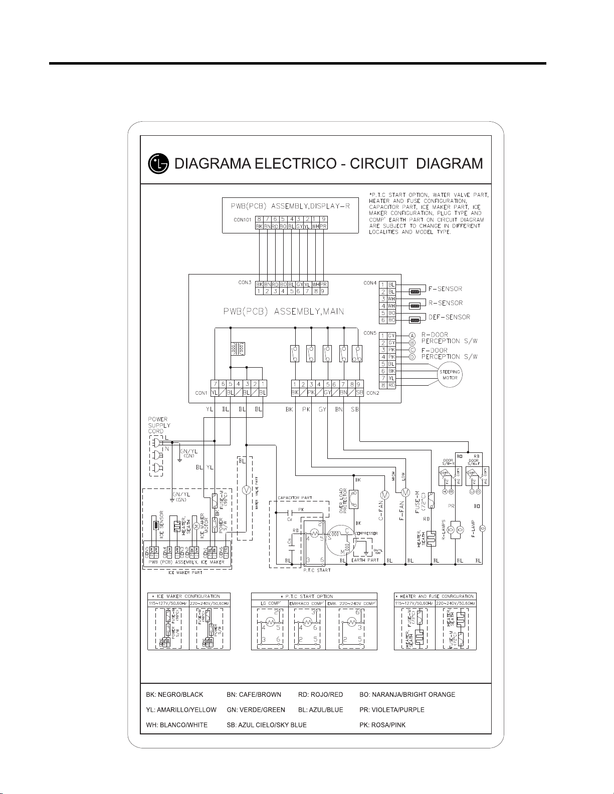
Good / Better
- 13 -
GY: GRIS/GRAY
Page 14
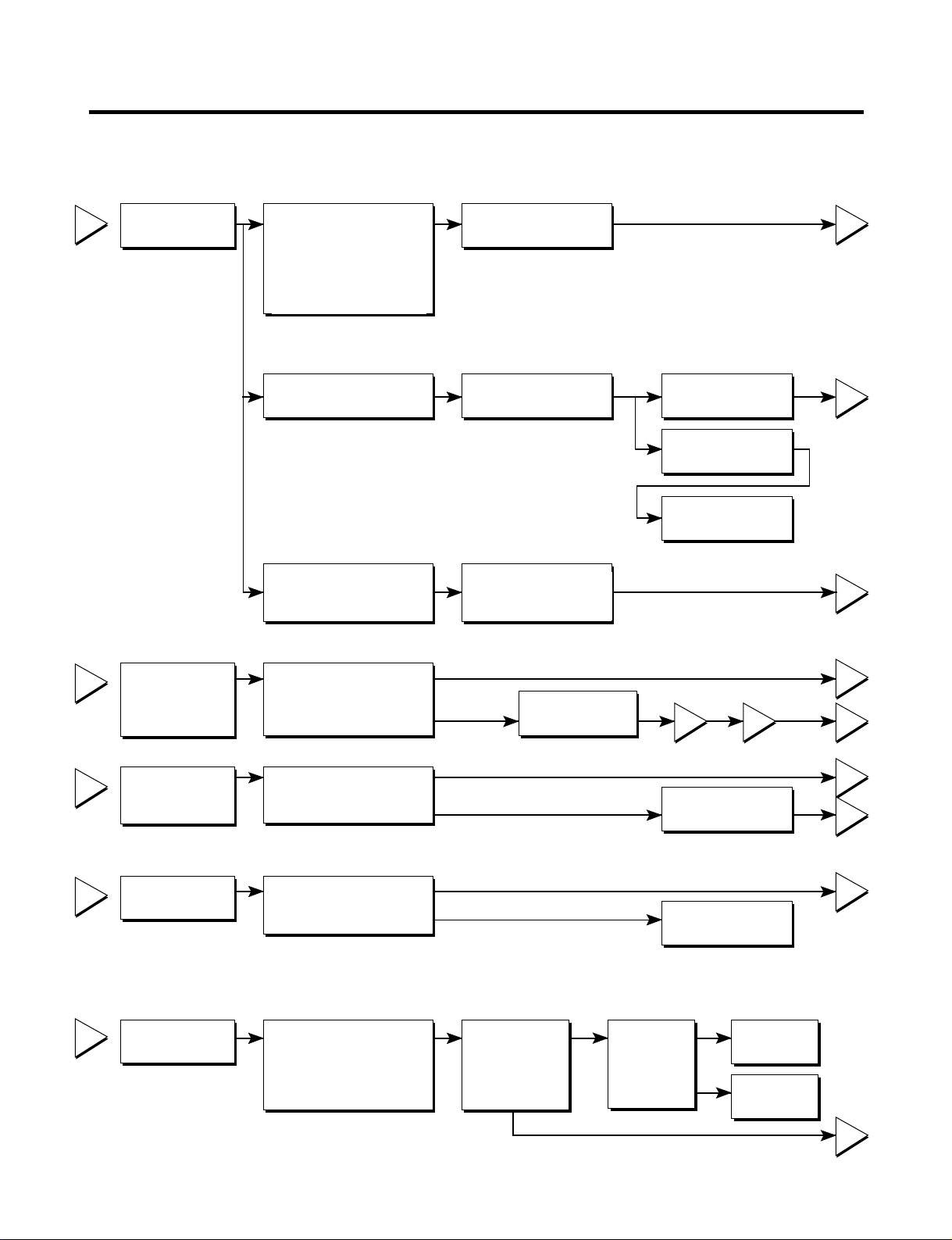
6. TROUBLESHOOTING
1
2
3
4
5
2
5
5
3
5
4
5
5
1
43
YES
YES
The range of resistance is between 1~50Ω (OK)
Not open
4.5~9 Ω
Open
Open or short
Open or short
YES
YES
NO
NO
NO
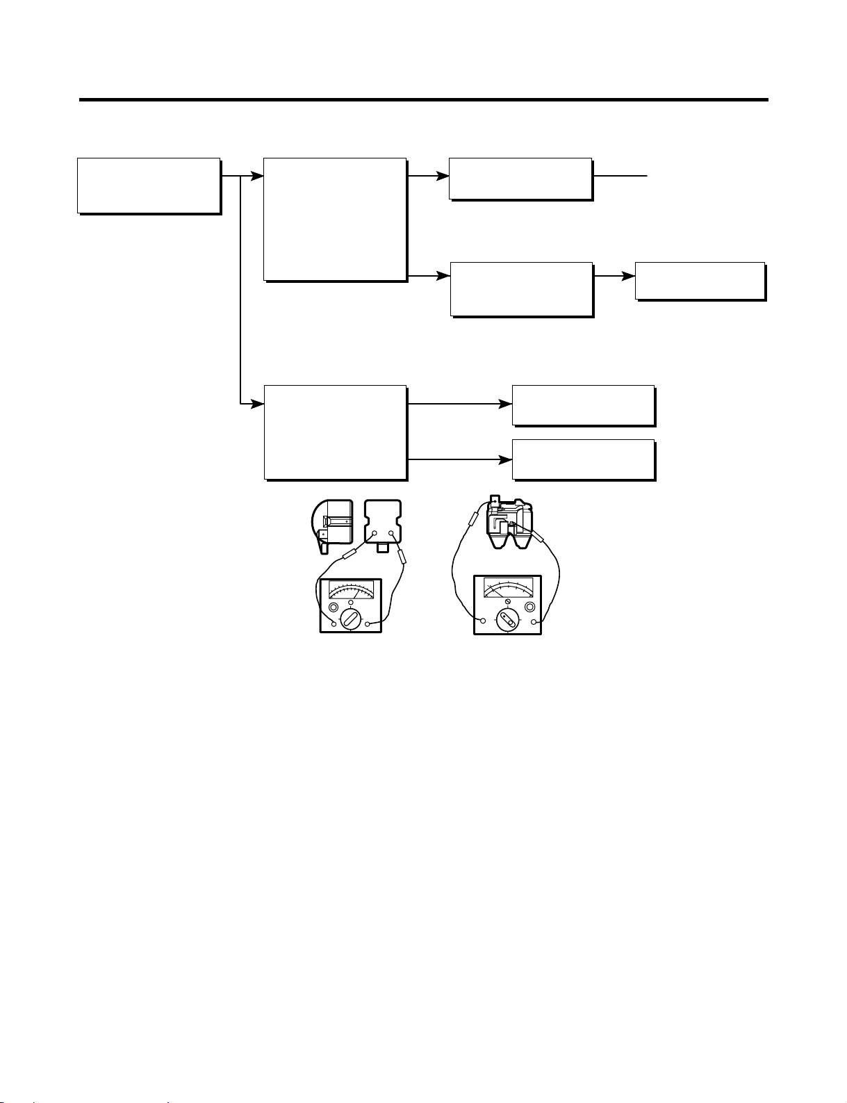
6-1 COMPRESSOR AND ELECTRIC COMPONENTS
Power Source.
Remove PTC-Starter
from Compressor and
measure voltage
between Terminal C of
Compressor and
Terminals 5 or 6 of PTC.
No Voltage.
Applied voltage isn't
in range of Rating
Voltage ±10%.
(Reated Voltage
±10%)?
OLP disconnected?
Advise customer that
power supply needs to be
checked by an electrician.
Replace OLP.
Check connection
condition.
Reconnect.
Check
resistance of
Motor
Compressor.
Check
resistance of
PTC-Starter.
Check resistance
between M-C, S-C and
M-S in Motor
Compressor.
Check resistance of
two terminals in
PTC-Starter.
Replace
Compressor.
Replace
PTC-Starter.
Check OLP.
Check
starting state.
Check resistance of two
terminals in OLP.
Check the power supply
under load.
(Compressor attempting
to re-start after being off
for 5 minutes).
Supply
voltage rating
with ±10%.
Replace OLP.
Did
compressor
start?
Compressor
is OK
Replace the
compressor
- 14 -
Page 15
6-2 PTC AND OLP
65
Shows continuity
Open
Normal operation of
Compressor is
impossible or poor.
Separate PTC-Starter
from Compressor and
measure resistance
between No. 5 and 6
of PTC-Starter with a
Tester.
(Figure 14)
Separate OLP from
Compressor and check
resistance value
between two terminals
of OLP with a Tester.
(Figure 15)
Observation value is
115V/60Hz : 6.8Ω±30%
The resistance value
is 0Ω (short) or
∞ (open).
Check another
electric component.
Replace OLP.
Replace PTCStarter.
Figure 14
Figure 15
- 15 -
Page 16
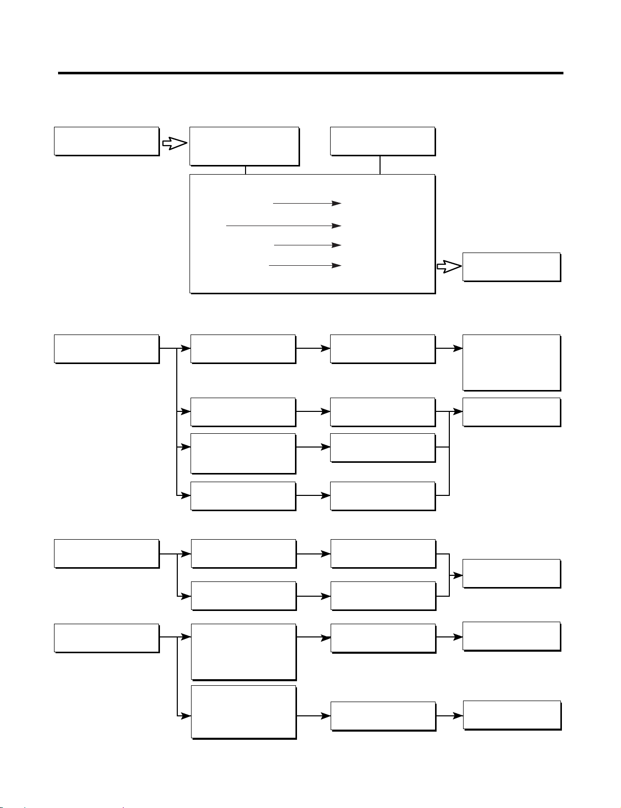
6-3 OTHER ELECTRICAL COMPONENTS
▼ Not cooling at all
Compressor
doesn't run.
▼ Poor cooling performance
Compressor runs
poorly.
Check for open short or
incorrect resistance readings
in the following components
a. Starting devices
b. OLP
c. Compressor coil
d. Wiring harness
Check starting
voltage.
Check voltage at
starting devices.
Cause
Short, open, or broken.
Poor contact
or shorted.
Coil open or shorted.
Poor contact
or shorted.
Low voltage.
Poor or broken or
open contact.
Replace
indicated component.
Advise customer that
the Power supply
needs to be checked
by an electrician.
Replace
indicated component.
Fan motor
doesn't run.
Heavy frost buildup on
EVAPORATOR.
Check current flowing
in sub-coil of
Compressor.
Check rating of OLP.
Check wiring circuit.
Check Fan Motor.
Check current flow in
the following
components:
Sensor
Fuse-M
Check current flow in
the Defrost Heater.
Shorted.
Lack of capacity.
Wire is open or
shorted.
Coil is shorted
or open.
Open.
Open.
Replace
indicated component.
Replace
indicated component.
Replace
Defrost Heater.
- 16 -
Page 17
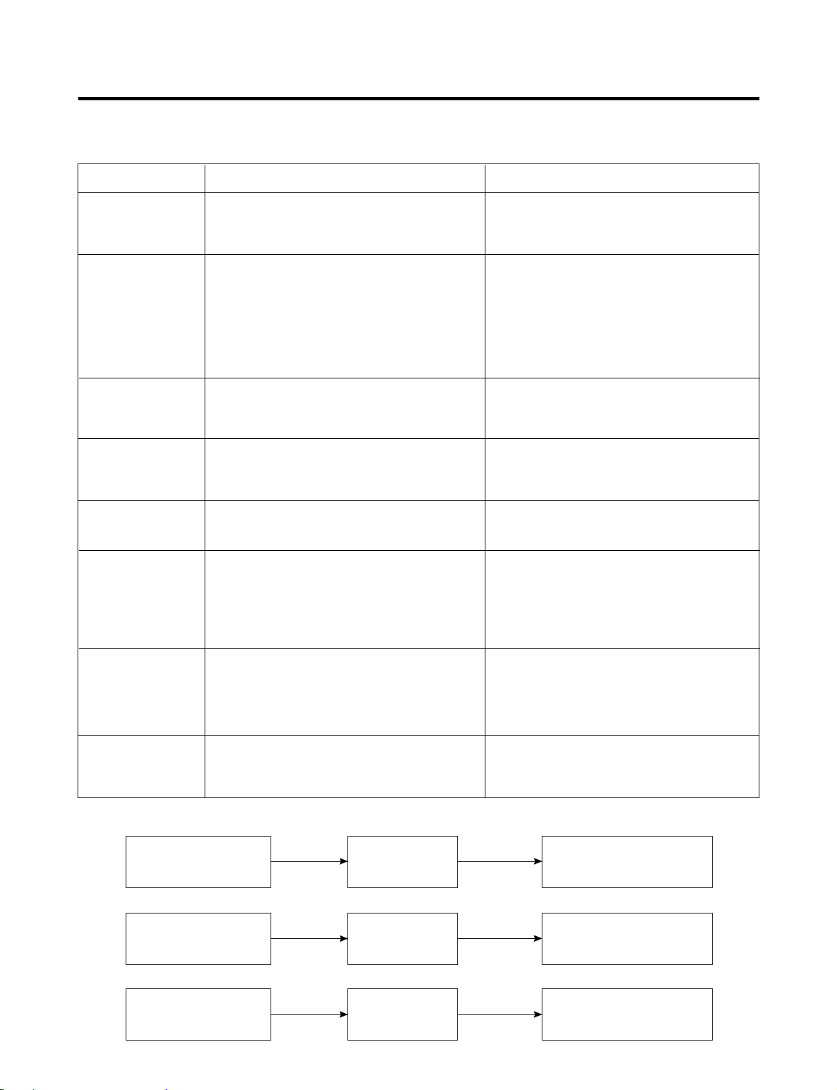
6-4 SERVICE DIAGNOSIS CHART
COMPLAINT POINTS TO BE CHECKED REMEDY
No Cooling.
Cools poorly.
Foods in the
Refrigerator
are frozen.
Condensartion or ice
forms inside
the unit.
Condensartion forms
in the Exterior Case.
There is abnormal
noise.
• Is the power cord unplugged from the outlet?
• Check if the power switch is set to OFF.
• Check if the fuse of the power switch is shorted.
• Measure the voltage of the power outlet.
• Check if the unit is placed too close to the wall.
• Check if the unit is placed too close to the stove,
gas cooker, or in direct sunlight.
• Is the ambient temperature too high or
the room door closed?
• Check if food put in the refrigerator is hot.
• Did you open the door of the unit too often
or check if the door is sealed properly?
• Check if the Control is set to Warm position.
• Is food placed in the cooling air outlet?
• Check if the control is set to colder position.
• Is the ambient temperature below 41°F(5°C)?
• Is liquid food sealed?
• Check if food put in the refrigerator is hot.
• Did you open the door of the unit too
often or check if the door is sealed properly?
• Check if the ambient temperature and humidity
of the surrounding air are high.
• Is there a gap in the door gasket?
• Is the unit positioned in a firm and even place?
• Are any unnecessary objects placed
in the back side of the unit?
• Check if the Drip Tray is not firmly fixed.
• Check if the cover of the compressor enclosure
in the lower front side is taken out.
• Plug into the outlet.
• Set the switch to ON.
• Replace the fuse.
• If the voltage is low, correct the wiring.
• Place the unit about 4 inches (10 cm) from the wall.
• Place the unit away from these heat sources.
• Lower the ambient temperature.
• Put in foods after they have cooled down.
• Don't open the door too often and close
it firmly.
• Set the control to Recommended position.
• Place foods in the high-temperature section.
(front part)
• Set the control to Recommended position.
• Set the control to Warm position.
• Seal liquid foods with wrap.
• Put in foods after they have cooled down.
• Don't open the door too often and close
it firmly.
• Wipe moisture with a dry cloth. It will disappear
in low temperature and humidity.
• Fill up the gap.
• Adjust the Leveling Screw, and position the
refrigerator in a firm place.
• Remove the objects.
• Fix the Drip Tray firmly in the original position.
• Place the cover in its original position.
Door does not
close well.
Ice and foods
smell unpleasant.
● Other possible problems:
Check if frost forms in
the freezer.
Check the
refrigeration system.
Check the
Thermistor.
• Check if the door gasket is dirty with
an item like juice.
• Is the refrigerator level?
• Is there too much food in the refrigerator?
• Check if the inside of the unit is dirty.
• Are foods with a strong odor unwrapped?
• The unit smells of plastic.
Not
defrosting
The system
is faulty.
The operation of
the Thermistor is
incorrect.
• Clean the door gasket.
• Position in the firm place and level the
Leveling Screw.
• Make sure food stored in shelves does not prevent
the door from closing.
• Clean the inside of the unit.
• Wrap foods that have a strong odor.
• New products smell of plastic, but this
will go away after 1-2 weeks.
Check Components
of the defrosting
circuit.
Perform sealed
system repair.
Replace the
Thermistor.
- 17 -
Page 18
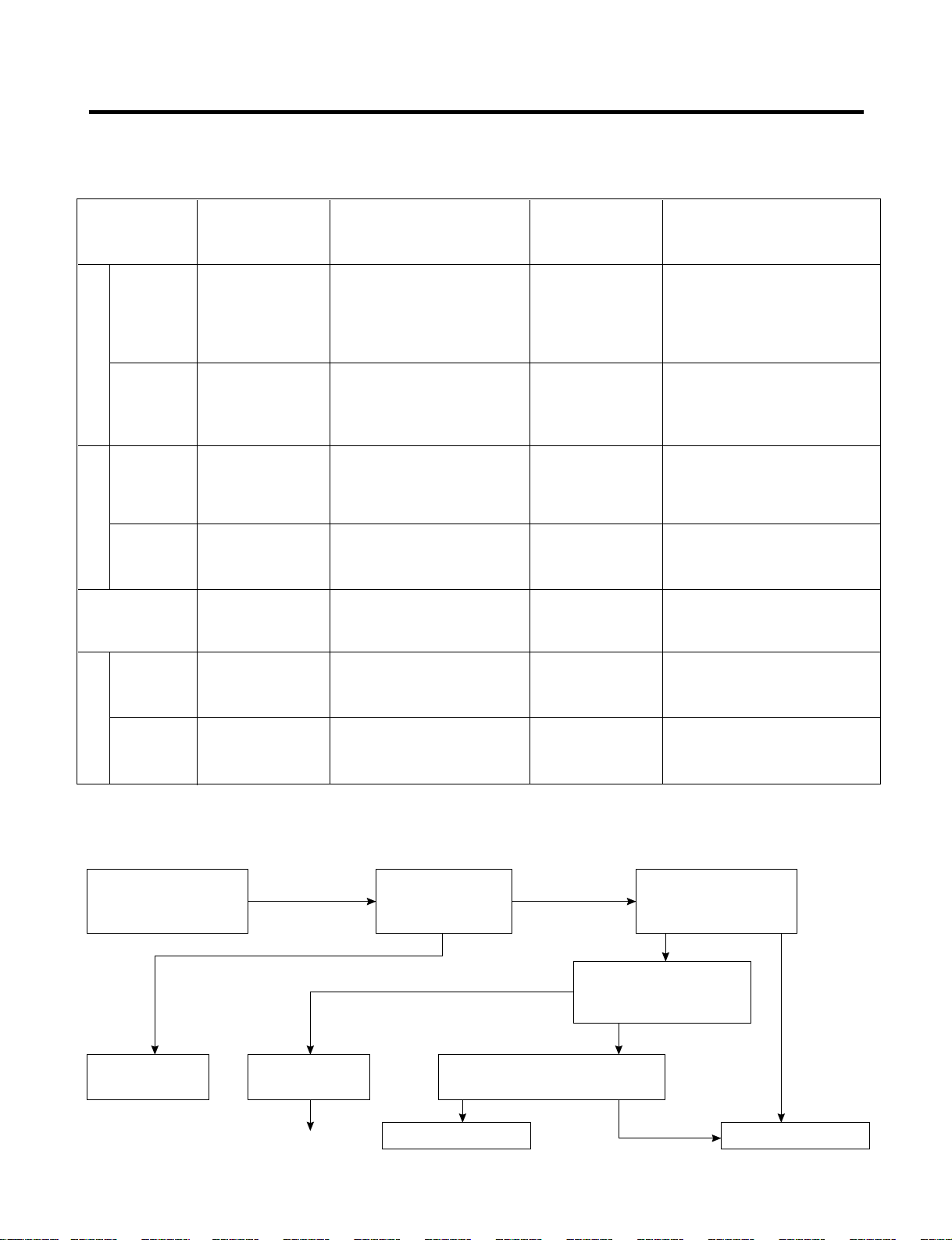
6-5 REFRIGERATION CYCLE
YES
YES
▼ Troubleshooting Chart
CAUSE
PARTIAL Freezer Low flowing sound of A little higher • Refrigerant level is low due
LEAKAGE compartment and Refrigerant is heard and than ambient • to a leak.
LEAKAGE
COMPLETE Freezer Flowing sound of refrigerant Equal to ambient • No discharging of Refrigerant.
LEAKAGE compartment and is not heard and frost isn't temperature. • Normal cooling is possible by
CLOGGED BY DUST
PARTIAL Freezer Flowing sound of refrigerant A little higher • Normal discharging of the
CLOG compartment and is heard and frost forms than ambient • refrigerant.
WHOLE
CLOG
MOISTURE Cooling operation Flowing sound of refrigerant Lower than • Cooling operation restarts
CLOG stops periodically. is not heard and frost melts. ambient • when heating the inlet of the
COMPRESSION
COMP- Freezer and Low flowing sound of A little higher • Low pressure at high side
DEFECTIVE
RESSION Refrigerator refrigerant is heard and ambient • of compressor due to low
STATE OF
THE UNIT
Refrigerator don't frost forms in inlet only. temperature. • Normal cooling is possible by
cool normally. • restoring the normal amount of
Refrigerator don't formed. • restoring the normal amount of
cool normally. • refrigerant and repairing the leak.
Refrigerator don't in inlet only. temperature. • The capillary tube is faulty.
cool normally.
Freezer
compartment and
Refrigerator don't cool.
don't cool. frost forms in inlet only. temperature. • refrigerant level.
STATE OF THE
EVAPORATOR
Flowing sound of refrigerant Equal to ambient • Normal discharging of the
is not heard and frost isn't temperature. • Refrigerant.
formed.
TEMPERATURE
OF THE
REMARKS
COMPRESSOR
• refrigerant and repairing the leak.
temperature. • capillary tube.
NO COMP- No compressing Flowing sound of refrigerant Equal to ambient • No pressure in the high
RESSION operation. is not heard and there is temperature. • pressure part of the
no frost. • compressor.
▼ Leakage Detection
● Observe the discharging point of the refrigerant, which may be in the oil discharging part of the compressor and in a hole
in the evaporator.
Check if compressor
runs.
Frost formed normally
Moisture Clog
Faulty
Compressor.
Check Compressor
Check if frost
forms in
Evaporator.
Normal amount
Clogged by dust. Gas leakage.
No frost
or frost forms
in inlet only
Observe the discharged
amount of Refrigerant.
Inject refrigerant in compressor
and check cooling operation.
Frost formed normally
Check if oil
leaks.
None or too much
(Find the leak and repair it)
- 18 -
Page 19
▼ General Control of Refrigerating Cycle
NO. ITEMS UNIT STANDARDS PURPOSES REMARKS
Pipe and
1
piping system
opening time
Welding
2
N
2 sealed
3
parts
Refrige-
4
ration
Cycle
Evacuation
time
Vacuum
degree
Vacuum
Vacuum
piping
Min.
Nitrogen
pressure
Confirm
N
2 leak
Min.
Torr
EA
EA
Pipe: within 1 hour.
Comp: within 10 minutes.
Drier: within 20 minutes.
Weld under Nitrogen
atmosphere.
(N
2 pressure:
0.1~0.2 kg/cm
2
)
Confirm the sound of
pressure relief when
removing the rubber cap.
Sound: usable
No sound: not usable
More than 40 minutes
Below 0.03 (ref)
High and low pressure sides
are evacuated at the same
time for models above 200 l.
Use R-134a manifold
exclusively.
To protect
moisture
penetration.
To protect oxide
scale formation.
To protect
moisture
penetration.
To remove moisture.
To protect mixing
of mineral and
ester oils.
The opening time should be reduced
to a half of the standards during rain
and rainy seasons (the penetration of
water into the pipe is dangerous).
- Refer to repair note in each part.
- R-134a refrigerant is more
susceptible to leaks than R-12 and
requires more care during welding.
-
Do not apply force to pipes before and
after welding to protect pipe from cracking.
- In case of evaporator parts, if it doesn't
make sound when removing rubber
cap, blow dry air or N
2 gas for more
than 1 min. and than use the parts.
Note: Only applicable to the model
equipped with reverse flow
protect plate.
Vacuum efficiency can be improved
by operating compressor during
evacuation.
The rubber pipes for R-12 refrigerant
will be melted when they are used for
R-134a refrigerant (causes of leak.)
Refrigerant
5
weighing
Drier
6
replacement
Leak check
7
Pipe
coupler
Outlet
(Socket)
Plug
EA
EA
Use R-134a manifold
exclusively.
R-134a manifold exclusively.
R-134a manifold exclusively.
Use R-134a exclusively.
Weighing allowance: ±5g
Note: Winter: -5g
Summer: +5g
- Use R-134a exclusively for
R-134a refrigerator.
-
Replace drier whenever repairing
refrigerator cycle piping.
- Do not use soapy water for
check. It may be sucked
into the pipe by a vacuum.
To protect R-12
refrigerant mixing.
To protect R-12
refrigerant mixing.
To protect R-12
refrigerant mixing.
Do not mix with
R-12 refrigerant.
To remove the
moisture from
pipe inside.
Defect in
refrigerant leak
area.
- Do not weigh the refrigerant at too
hot or too cold an area.
(77°F [25°C] is adequate.)
- Make Copper charging canister
(Device filling refrigerant)
Socket: 2SV Plug: 2PV R-134a
Note: Do not burn O-ring (bushing)
during welding.
- Check for an oil leak at the refrigerant
leak area. Use an electronic leak
detector if an oil leak is not found.
- The electronic leak detector is very
sensitive to halogen gas in the air. It
also can detect R-141b in urethane.
Practice many times before using this
type of detector to avoid false readings.
- 19 -
Page 20
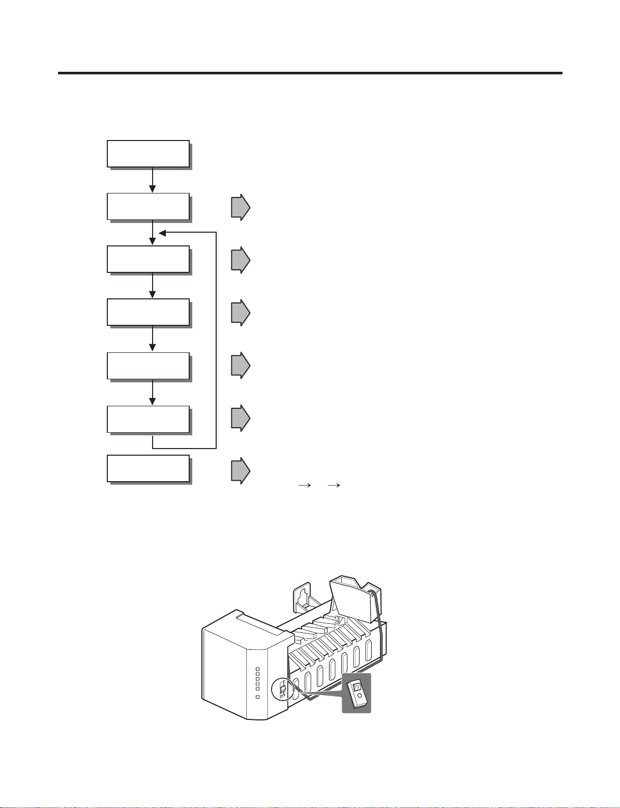
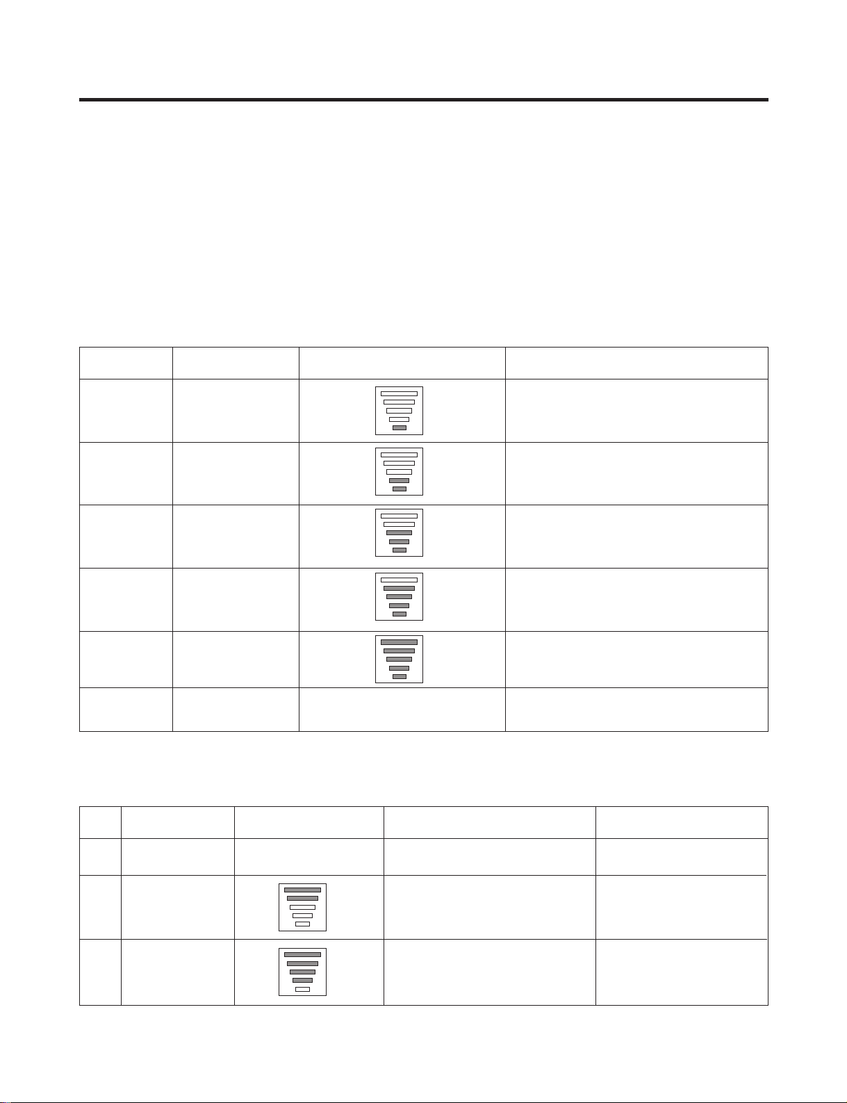
7. OPERATION PRINCIPLE AND REPAIR METHOD OF ICEMAKER
• Adjusts EJECTOR to Start Position with power on.
Power On
Start Position
Ice Making
Mode
Harvest
Mode
Park Position
Fill
Test Mode
• Waits until water becomes cold after starting the
ice making operation.
• Runs MOTOR to drop ice from the tray the ICE BIN.
• Performs Ice Making Mode after supplying water by operating
the SOLENOID in ICE VALVE.
• To operate LINE and SERVICE, press and hold the Fill Key
for 3 seconds. The ice maker will run through 3 stages:
Harvest Fill Icemaking.
• With the detect lever, checks if the ICE BIN is full.
7-1 OPERATION PRINCIPLE
7-1-1 Operation Principle of IceMaker
1. Turning the Icemaker stop switch off (O) stops the ice making function.
2. Setting the Icemaker switch to OFF and then turning it back on will reset the icemaker control.
- 20 -
Page 21
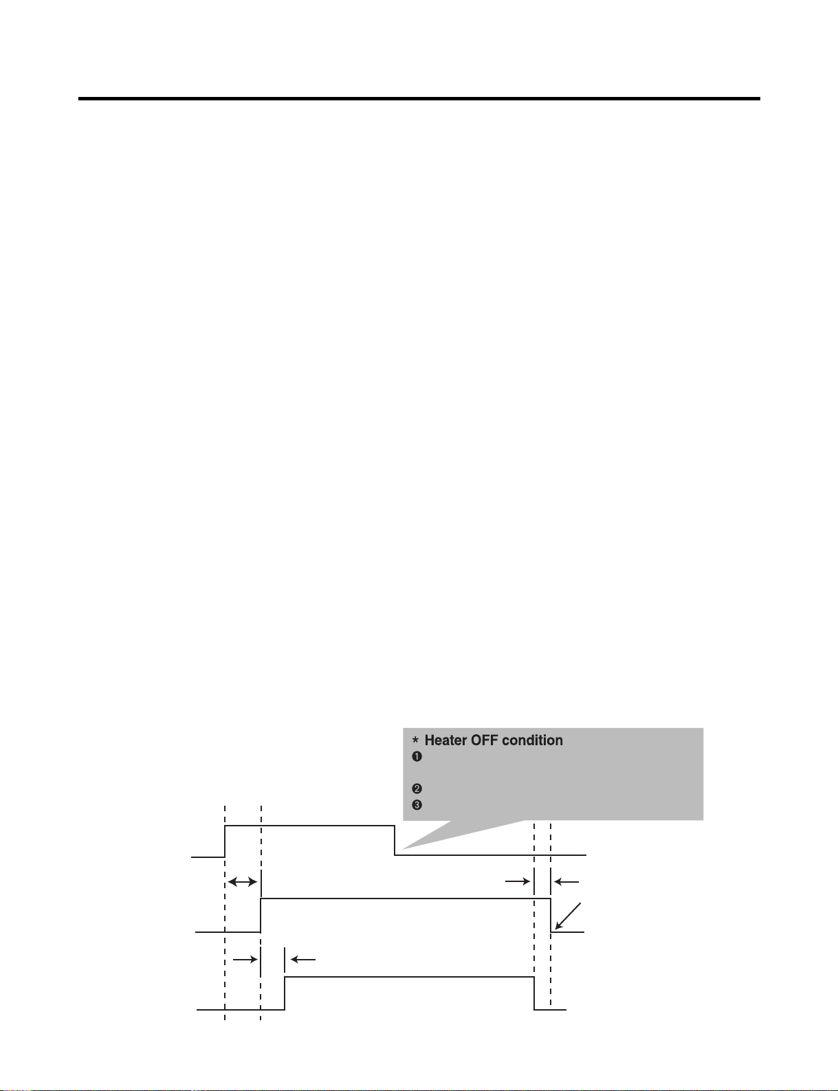
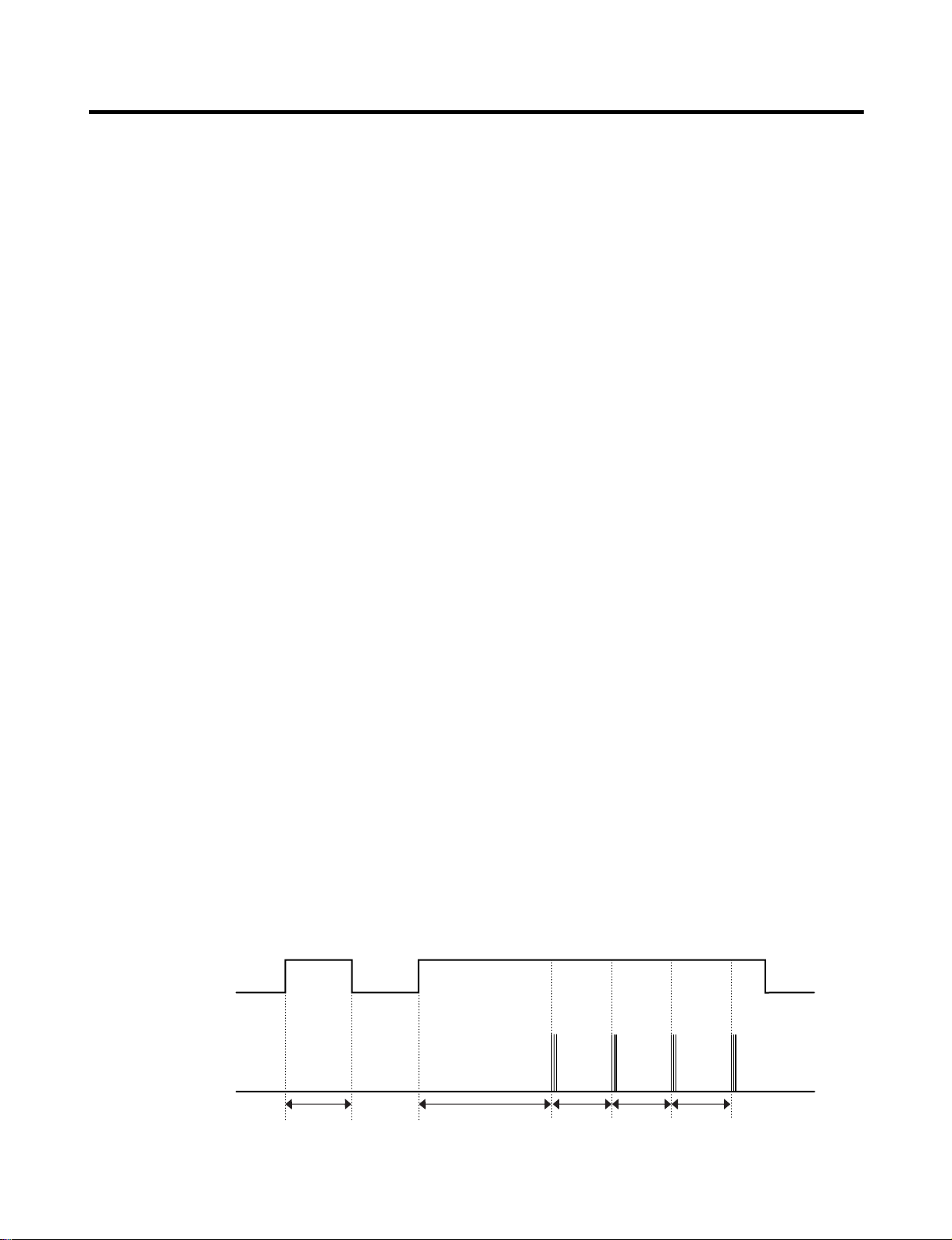
7-2 CONTROL METHOD ACCORDING TO FUNCTIONS
Heater
on
off
on
0V
5V
off
30 sec.
10 sec.
Motor
Hall IC
Ice removing
completion point
2 ms
Ice making sensor temperature is 50°F(10˚C)
or more
Max. 18 minutes
After detect LEVER rises
7-2-1 Start Position
1. After POWER OFF or Power Outage, check the EJECTOR's position with MICOM initialization to restart.
2. How to check if it is in place:
- Check HIGH/LOW signals from HALL SENSOR in MICOM PIN.
3. Control Method to check if it is in place:
(1) EJECTOR is in place,
- It is an initialized control, so the mode can be changed to ice making control.
(2) EJECTOR isn't in place:
A. If EJECTOR is back in place within 2 minutes with the motor on, it is being initialized. If not, go to Step B.
B. If EJECTOR is back in place within 18 minutes with the heater on (to control Heater on its OFF condition), it is being
initialized. If not, it is not functioning. Repeat Step B with Heater and Motor off.
7-2-2 Ice Making Mode
1. Ice Making control refers to the freezing of supplied water in the ice trays. Complete ice making operations by measuring
the temperature of the Tray with Ice-Making SENSOR.
2. Ice Making starts after completing fulfilled ice control and initial control.
3. The Ice Making function is completed when the sensor reaches 19°F(-7°C), 60 to 240 minutes after starting.
4. If the temperature sensor is defective, the ice-making function will be completed in 4 hours.
7-2-3 Harvest Mode
1. Ice-removing control refers to the operation of dropping cubes into the ice bin from the tray when ice-making has
completed.
2. Ice removing control mode:
(1) Operates Heater for 30 seconds; then operate MOTOR.
(2) After performing Step 1 (to control the Heater on its off condition), Ice-Removal control will be back in place wthin 18
minutes. (Hall SENSOR sign = OV). Ice removal is then complete. Then change the mode to the water supply control.
If this control phase fails to start, it is not functioning. Put the Heater and Motor in the off position. Restart every 2
hours. (Refer to fig.1)
NOTE : If the motor malfunctions and starts before the detect lever rises, MICOM regards the Ice-Removing phase as
completed. Water then starts flowing. To prevent this, MICOM doesn’t switch to water-supply mode, but restarts the iceremoving mode. If this happens 3 times, the motor is malfunctioning and you should stop the loads (Heater, Motor). Then
restart the Ice-Removing mode every 2 hours. (See Step 2 above.)
<fig1. Ice removing process>
- 21 -
Page 22
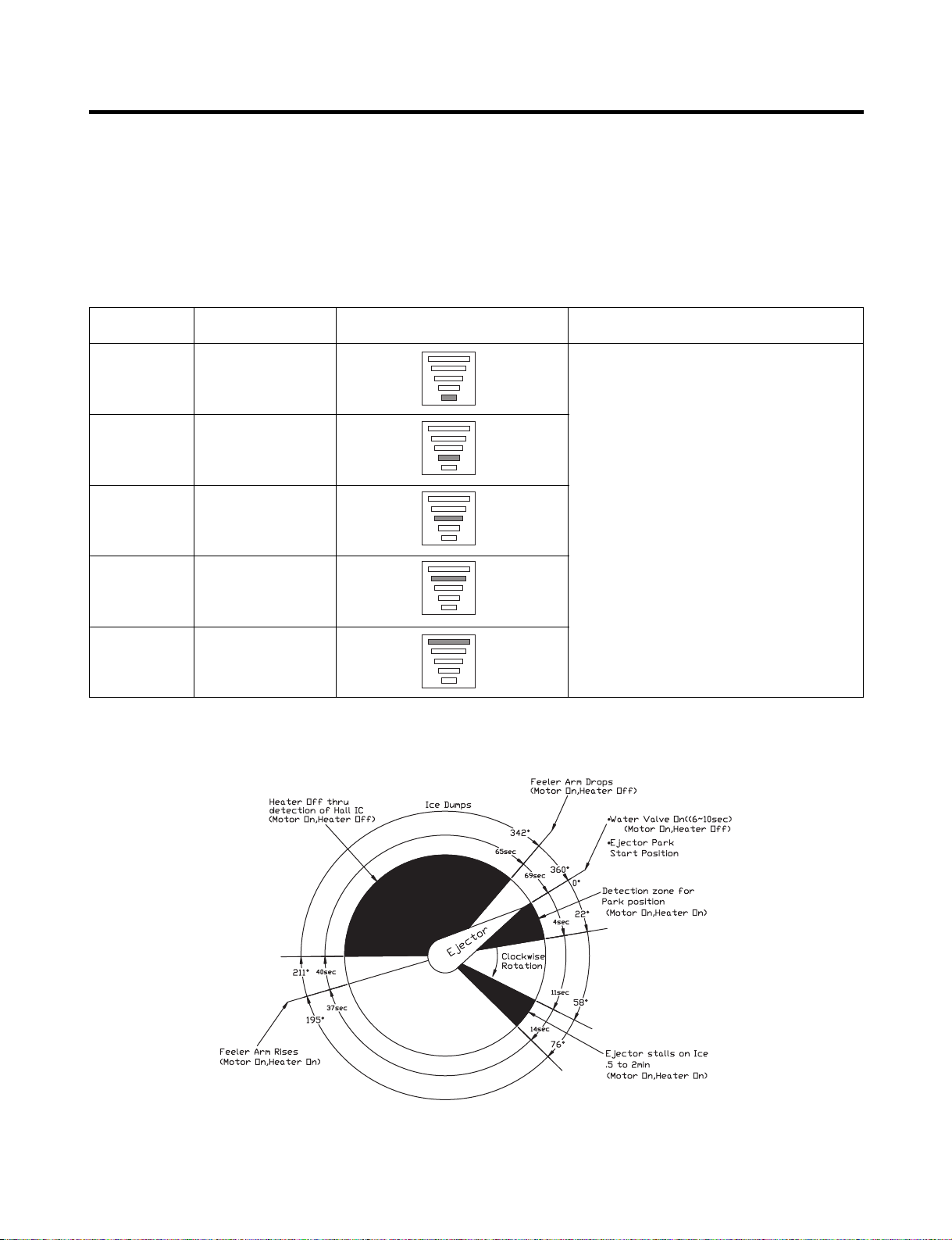
7-2-4 Fill / Park Position
1. When Ice-Removing control (Normal Ice-Removing control, Ice-Removing control for test) has completed, and the
EJECTOR is in place, this control operates the ICE SOLENOID by time check in the compressor enclosure of the
refrigerator. Then it supplies water to the ice making tray.
2. Water supply level is adjustable in levels 1-5 by pressing the water supply control Switch and fill time will be determined
by the selected level.
Water supply amount TABLE
STAGE TIME TO SUPPLY INDICATIONS REMARKS
1
2
3
4
5
NOTE : Below is an example used by another vendor as an explanation of what is taking place.
6 sec.
7 sec.
8 sec.
9 sec.
10 sec.
The water amount will vary depending
on the water control Switch setting, as
well as the water pressure of the
connected water line.
- 22 -
Page 23
7-2-5 Function TEST
1.
This is a compulsory operation for TEST, SVC, cleaning, etc. It is operated by pressing the water supply control KEY for 3 seconds.
2. It operates in the Ice Making mode, but not in the Ice-Removing mode or water supply process. (If there is an ERROR, it
can only be checked in the TEST mode.)
3. If the water supply control KEY is pressed for 3 seconds in the Ice-Making mode (no matter what condition the IceMaking tray is in) the Ice-Removing operation starts immediately. Water is not yet frozen, so water is poured instead of
ice. If the control doesn’t operate normally in the TEST mode, check and repair as needed.
4. After water is supplied, the normal CYCLE is followed: ice making → Harvest → Fill → Park Position.
5. When Stage 5 is completed in the TEST mode, minimize MICOM in 5 seconds, the time needed to supply water resets to
the previous status in the TEST mode.
Diagnosis TABLE
STAGE ITEMS INDICATOR REMARKS
1
2
3
4
5
6
HEATER
MOTOR
HALL IC (detection
of position) I
VALV E
HALL IC (detection
of full-filled Ice) II
reset
Mark previous status on TEST mode
Five seconds after heater starts, heater will
go off if temperature recorded by sensor is
10°C or lever is in up position.
Five seconds after heater starts, you can
confirm that motor is moving.
You can confirm Hall Ic detection of position.
Two seconds after detection of initial
position, you can confirm that valve is on.
You can check whether hall is sensing Full
ice condition. (If there is a full-filled error, the
fifth LED is not on.)
Five seconds after fifth stage is completed,
the icemaker reset at initial status.
7-3 DEFECT DIAGNOSIS FUNCTION
7-3-1 ERROR CODES shown on Ice Maker water supply control panel
NO DIVISION INDICATOR CONTENTS REMARKS
1
2
3
ERROR indicators in table can be checked only in TEST mode.
Normal
Ice-Making
Sensor
malfunction
Ice Maker Kit
malfunction
Mark time to
supply
Cut or short-circuited wire
When ejector blades don’t reach
park position over 18 minutes
since Harvest Mode starts.
None
Display switch
operates properly
Make sure that the wire
on each sensor is
connected.
Defects of
HALL IC/MOTOR/
HEATER/RELAY
- 23 -
Page 24
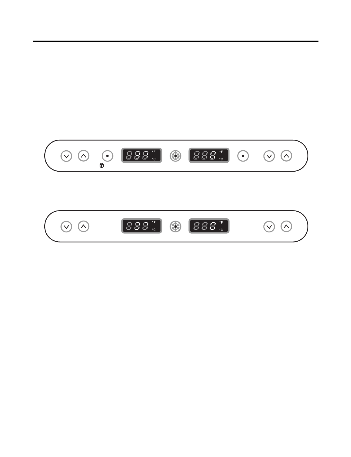
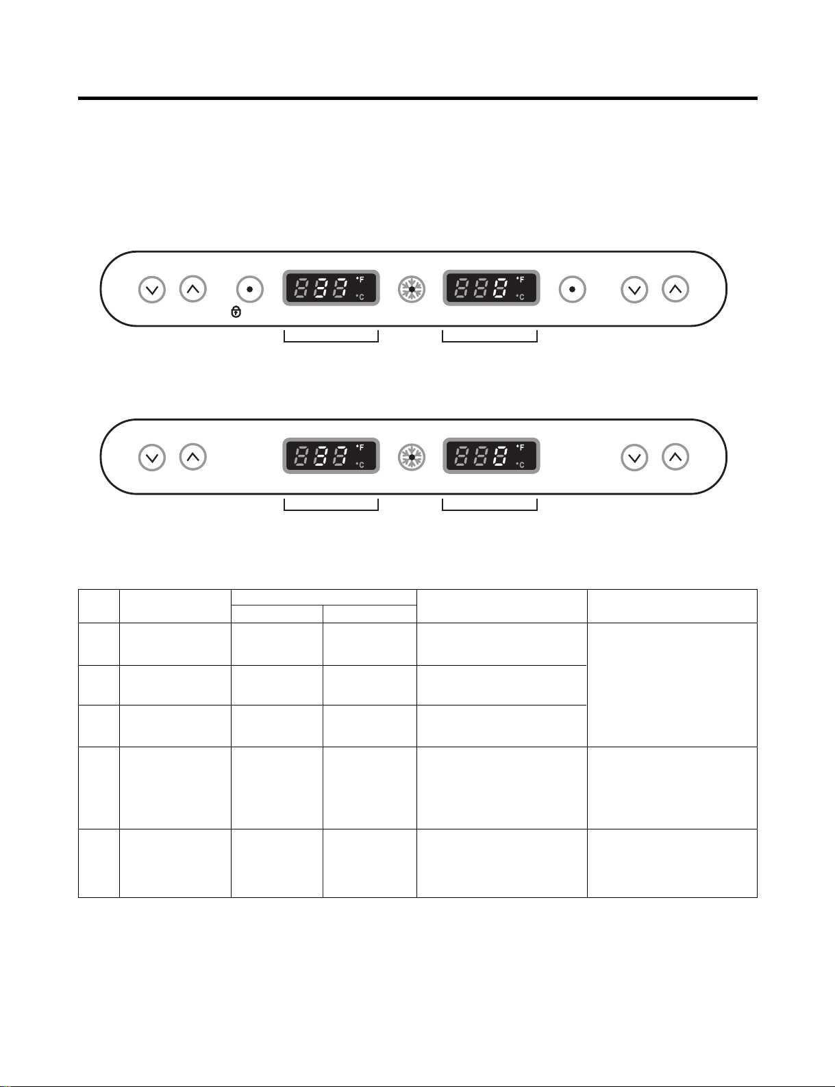
8. DESCRIPTION OF FUNCTION & CIRCUIT OF MICOM
REFRIGERATOR TEMP
COLDER WARMER LOCK 37 °F IS RECOMMENDED 0 °F IS RECOMMENDED
DISPENSER
FREEZER TEMP
COLDER WARMERRESET
WATER FILTER
EXPRESS
FREEZING
DISPENSER MODEL
REFRIGERATOR TEMP
COLDER WARMER 37 °F IS RECOMMENDED 0 °F IS RECOMMENDED
FREEZER TEMP
COLDER WARMER
EXPRESS
FREEZING
BEST MODEL
8-1 FUNCTION
8-1-1 Function
1. When the appliance is plugged in, it is set to 37 °F for the Refrigerator and 0 °F for the Freezer.
You can adjust the Refrigerator and the Freezer control temperature by pressing the COLDER button or the WARMER
button.
2. When the power is initially applied or restored after a power failure, it is set to the setting temperature as you set before
power off. (applied to DISPENSER MODEL)
Control range : 32°F ~ 46°F
0°C ~ 8°C
Control range : 32°F ~ 46°F
0°C ~ 8°C
8-1-2 How to Change the Temperature Mode to °F / °C
1. The setting temperature mode can be changed to °F / °C by pressing and holding COLDER key of Freezer and COLDER
key of Refrigerator over 1 seconds. at the same time.
2. The initial setting is °F. Whenever the mode is changed, the LED lights are changed.
8-1-3 Dispenser Lock
1. Press and hold the DISPENSER LOCK button for 3 seconds to lock the dispenser.
2. When locked, the LED is off and the dispenser function is turned off.
3. Press and hold the DISPENSER LOCK button again for 3 seconds to unlock the dispenser. The LED will be on and the
dispenser will function normally.
Control range : -6°F ~ 9°F
-21°C ~ -13°C
Control range : -6°F ~ 9°F
-21°C ~ -13°C
- 24 -
Page 25
8-1-4 CONTROL OF FREEZER FAN MOTOR
Closed Open Closed Open
3 Times 3 Times 3 Times 3 Times
Closed
Within 1 min. 1 min.
30 sec 30 sec 30 sec
Freezer Door
or Refrigerator
Door
Buzzer
1. Freezer fan motor has high and standard speeds.
2. High speed is used at power-up, for express freezing, and when refrigerator is overloaded.
Standard speeds is used for general purposes.
3. To improve cooling speed, the RPM of the freezer fan motor change from normal speed to high.
4. High speed (2700RPM) : Initial power on or load corresponding operation, express freezing.
Normal speed (2400RPM) : General working conditions.
5. Fan motor stops when refrigerator or freezer door opens.
8-1-5 EXPRESS FREEZING
1. The purpose of this function is to intensify the cooling speed of freezer and to increase the amount of ice.
2. Whenever selection switch is pressed, selection/release, the LED will turn ON or OFF.
3. If there is a power cutage and the refrigerator is power on again, EXPRESS FREEZING function will be canceled.
4. To activate these function, to press the Express Freezing key and the LED will turn ON. This function will remain activated
for 24 hrs. The first three hours the compressor and Freezer Fan will be ON. The next 21 hours the freezer will be
controlled at the lowest temperature. After 24 hours or if the Express Freezing key is pressed again, the freezer will return
to its previous temperature.
5. For the first three hours notice the following cases:
(1) Compressor and freezer fan (HIGH RPM) continuously operate for three hours.
(2) If defrost starts during EXPRESS FREEZING, EXPRESS FREEZING operates for the rest of time after defrost is
completed, when EXPRESS FREEZING operation time is less than 90 minutes.
If EXPRESS FREEZING operates for more than 90 minutes, the EXPRESS FREEZING will operate for two hours
after defrost is completed.
(3) If EXPRESS FREEZING is pressed during defrost, EXPRESS FREEZING LED is on but this function will start seven
minutes after defrost is completed and it shall operate for three hours.
(4) If EXPRESS FREEZING is selected within seven minutes after compressor has stopped, the compressor (compressor
delays seven minutes) shall start after the balance of the delay time.
(5) The fan motor in the freezer compartment runs at high speed during EXPRESS FREEZING .
6. For the rest of the 21 hours, the freezer will be controlled at the lowest temperature.
8-1-6 REFRIGERATOR LAMP AUTO OFF
1. To avoid heat damage caused by the lamp, it is turned off automatically when the refrigerator door is open for more than 7
minutes.
8-1-7 Alarm for Open Door
1. This feature sounds a buzzer when the freezer or refrigerator door is not closed within 1 minute after it is opened.
2. One minute after the door is opened, the buzzer sounds three times each for 1/2 seconds. These tones repeat every 30
seconds.
3. The alarm is cancelled when the freezer or the refrigerator is closed while the buzzer sounds.
- 25 -
Page 26
8-1-8 Buzzer Sound
When the button on the front Display is pushed, a Ding~ Dong~ sound is produced.
(Refer to the Buzzer Circuit 8-2-4 No. 3)
8-1-9 Defrosting (removing frost)
1. Defrosting starts each time the COMPRESSOR running time reaches 7 hours.
2. For initial power on or for restoring power, defrosting starts when the compressor running time reaches 4 hours.
3. Defrosting stops if the sensor temperature reaches 46.4°F(8°C) or more. If the sensor doesn’t reach 46.4°F(8°C) in
2 hours, the defrost mode is malfunctioning. (Refer to the defect diagnosis function, 8-1-13.)
4. Defrosting won’t function if its sensor is defective (wires are cut or short circuited)
8-1-10 Filter Replacement Indication
1. In 6 months after the UNIT (refrigerator) is power on, or after 28,000 seconds of dispenser use, the water filter Indicator
LED (red color) will be ON.
2. When the water filter indicator LED is illuminated, you should change the water filter. After this, you must press the water
filter button for three seconds and you will hear a ding-dong sound.
The LED will be OFF. This operation will indicate that the UNIT is reset to its initial conditions, so this process is restarted.
8-1-11 Power Failure Compensation Function
1. When the UNIT is power off, the Fresh Food and Freezer Temperature notches, the filter elapsed time for replacement,
the temperature mode (°C or °F) and the dispenser lock mode are saved in the EEPROM.
2. When the UNIT is power on, the MICOM will read the specified EEPROM addresses to restore the values indicated in the
previous paragraph.
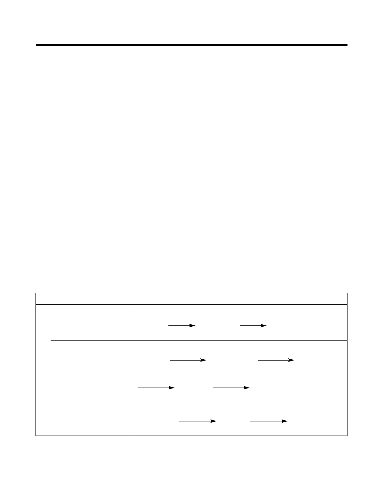
8-1-12 Electrical Parts Are Turned On Sequentially
Electrical parts such as COMP, defrosting heater, freezer FAN, etc. are turned on in the following order to prevent noise and
parts damage. Several parts are started at the same time at initial power on and are turned off together when TEST is
completed.
OPERATING ORDERS
Temperature of Defrosting
Sensor is 113°F(45°C) or
more (when unit is newly
Initial power on
purchased or when moved)
Temperature of defrosting
sensor is lower than
113 °F(45°C)
(when power cuts, SERVICE)
Reset to normal operation
from TEST MODE
POWER
in 1/2 second in 1/2 second
ON
POWER
in 1/2 second
ON
in 1/2 second in 1/2 second
COMP
ON
Total load
in 7 minute
OFF
COMP
ON
Defrosting
heater ON
COMP
ON
Freezer FAN
in 10 second
Freezer FAN
ON
in 1/2 second
ON
Defrosting
heater OFF
Freezer FAN
ON
- 26 -
Page 27
8-1-13 Defect Diagnosis Function
Defect code signs Defect code signs
Defect code signs Defect code signs
REFRIGERATOR TEMP
COLDER WARMER LOCK 37 °F IS RECOMMENDED 0 °F IS RECOMMENDED
DISPENSER
FREEZER TEMP
COLDER WARMERRESET
EXPRESS
FREEZING
DISPENSER MODEL
REFRIGERATOR TEMP
COLDER WARMER 37 °F IS RECOMMENDED 0 °F IS RECOMMENDED
FREEZER TEMP
COLDER WARMER
EXPRESS
FREEZING
BEST MODEL
WATER FILTER
1. Automatic diagnosis makes servicing the refrigerator easy.
2. When a defect occurs, the buttons will not operate; but the tones. such as ding. will sound.
3. When the defect CODE removes the sign, it returns to normal operation (RESET).
4. The defect CODE shows on the Refrigerator and Freezer Display.
ERROR CODE on display panel
NO ITEM
Failure of freezer
1
sensor
Failure of
2
Refrigerator sensor
Failure of defrost
3
sensor
Failure of defrost
4
mode
Failure of BLDC
FAN MOTOR at
5
freezing
compartment.
ERROR CODE
FS
rS
dS
dH
FF
Er
Er
Er
Er
Er
CONTENTS REMARKS
Cut or short circuit wire
Cut or short circuit wire
Inspect Connecting wires
Cut or short circuit wire
Snapping of defrost heater
When defrost sensor
doesn’t reach 8°C within 2
hours after starting defrost.
If there is no fan motor
signal For more than
65sec. in Operation fan
motor
or Temperature fuse, pull-
out of Connector (indicated
minimum 2 Hours after
Poor motor, hooking to
Wires of fan, contact of
structures to fan, snapping
or short circuit of Lead wire
on each sensor
failure occurs)
- 27 -
Page 28

8-1-14 TEST Mode
1. The Test mode allows checking the PCB and the function of the product as well as finding out the defective part in case of
an error.
2. The test mode is operated by pressing two buttons at Display panel.
3. While in the test mode, the function control button is not recognized, but the recognition tone (beep~) sounds.
4. After exiting the test mode, be sure to reset by unplugging and then plugging in the appliance.
5. If an error, such as a sensor failure, is detected while in the test mode, the test mode is cleared and the error code is
displayed.
6. While an error code is displayed, the test mode will not be activated.
MODE MANIPULATION CONTENTS REMARKS
TEST1
TEST2
Reset
NOTE : LED CHECK MODE: When the WARMER button in the refrigerator temperature control and the WARMER button in
the freezer temperature control are pushed and held for 1 second or longer, every LED on the display turns on at
the same time. When the buttons are released, the previous mode is restored.
Push Express Freezing
key and COLDER KEY of
Freezer Temp. at the
same time over 3
seconds.
Push Express Freezing
key and COLDER KEY of
Freezer Temp. at the
same time over 3 seconds
in TEST MODE 1
Push Express Freezing
key and COLDER KEY of
Freezer Temp. at the same
time over 3 seconds. in
TEST MODE 2
1. Continuous operation of the
COMPRESSOR
2. Continuous operation of the freezer fan
3. STEPPING DAMPER OPEN
4. Defrosting Heater OFF
5. Every DISPLAY LED ON
1. COMP OFF
2. Freezer FAN OFF
3. STEPPING DAMPER CLOSE
4. Defrosting heater ON
5. DISPLAY LED shows 222
Reset to the previously setting before
TEST MODE
Reset if the
temperature of the
Defrosting sensor
is 46°F(8°C) or more.
The compressor will
Start after a 7-minute
delay.
* Freezer Fan RPM Variable Check:
In case the freezer fan is in operation when the WARMER KEY in Refrigerator and Freezer Temp. Control are pressed for
more than one second at the same time freezer fan RPM changes. (for example if high speed, to normal speed or if
normal speed, to high speed for 30 seconds)
After 30 seconds, it turns to its original RPM.
* Demostration MODE:
1. When the WARMER KEY of refrigerator Temp. control or of freezer Temp. control in the the warmest temperature’s
status are pushed and held for 3 seconds or longer, It converts to Demonstration Mode.
2. It shows OFF on the display panel.
3. In this status, all Loads are off (Compressor / Fan / Damper / Heater)
(Even is Demonstration Mode, the refrigerator Lamp automatic off function warks normally and can be demonstrated)
4. Exit the test mode and reset the display by pressing the COLDER and WARMER buttons.
- 28 -
Page 29

8-2 PCB FUNCTION
8-2-1 Power Circuit
The secondary part of the TRANSFORMER is composed of the power supply for the display, the BLDC FAN Motor drive
(15.5 V), the relay drive (12 Vdc) and the MICOM and IC (5 Vdc).
The voltage for each part is as follows:
PART VA 1 CE 3 CE 4 CE 5
VOLTAGE 115 Vac 12 Vdc 15.5 Vdc 5 V
VA1 is a part for preventing over voltage and noise. When 385V or higher power is applied, the inside elements are shortcircuited and broken, resulting in blowout of the fuse in order to protect the elements of the secondary part of the
TRANSFORMER.
- 29 -
Page 30

8-2-2 Oscillation Circuit
- 30 -
This circuit generates the base clock for calculating time and the synchro clock for transmitting data from and to the inside
logic elements of the IC1 (MICOM). Be sure to use specific replacement parts, since calculating time by the IC1 may be
changed. If changed, the OSC1 SPEC will not work.
8-2-3 Reset Circuit
The RESET circuit allows all the functions to start at the initial conditions by initializing various parts, including the RAM
inside the MICOM (IC1) when the power is initially supplied or the power supply to the MICOM is restored after a
momentary power failure. For the initial 10ms of power supply, LOW voltage is applied to the MICOM RESET terminal.
During a normal operation, 5V is applied to the RESET terminal. (If a malfunction occurs in the RESET IC, the MICOM will
not operate.)
Page 31

8-2-4 Load / Buzzer Drive & Open Door Detection Circuit
- 31 -
FREEZER DOOR
SWITCH
REFRIGERATOR
DOOR SWITCH
G5SB-14
1. Load Drive Condition Check
LOAD TYPE
Measurement Location (IC6)
ON
Condition
OFF
COMP
DEFROSTING
HEATER
LAMP
TCM
POWER MODE
(OPTIONAL)
NO.13 NO.14 NO.16 NO.12 NO.15
1V or below
12V
VALV E
(DISPENSER
MDL)
2. Fan motor driving circuit (freezing compartment fan)
1. This circuit makes standby power 0 by cutting off power supplied to ISs inside of the fan motor in the fan motor OFF.
2. This is a circuit to perform a temporary change of speed for the fan motor and applies DC voltage up to 7.5V ~ 16V to motor.
3. This circuit prevents over-driving the fan motor by cutting off power applied to the fan motor in the lock of fan motor by
sensing the operation RPM of the fan motor.
part part part
a b
c
MOTOR OFF 2V or less 0V 5V
MOTOR ON 13V~15V 0V 2V~3V
Page 32

3. Buzzer Drive Condition Check
0 V
5 V
0 V
5 V
0.5 s 0.5 s
2.63 kz (Beep~)
OFF
0.05 s
0.1 s0.2 s 2 s
0 V
5 V
0 V
5 V
2.63 kz
(
Ding~)
2.21 kz (
Dong~)
FREEZER DOOR
SWITCH
REFRIGERATOR DOOR
SWITCH
Condition
Measure-
Tone (Ding~Dong~) when the button on
the display is pushed.
Alarm for open door
(beep-beep-beep)
ment Location
IC1 ( ) 0 V
A
IC1 ( ) 0 V
B
4. Open Door Detection Circuit Check
OFF
Freezer/
Refrigerator Door
Measurement
Location
Closed 5 V
Open 0 V
(PIN NO.63 & PIN NO.8)
- 32 -
Page 33

8-2-5 Temperature Sensor Circuit
FREEZER-SENSOR
REFRIGERATOR-SENSOR
DEFROST-SENSOR
The upper CIRCUIT reads REFRIGERATOR temperature, FREEZER Temperature, and DEFROST-SENSOR temperature
for defrosting and the indoor temperature for compensating for the surrounding temperature into MICOM.
OPENING or SHORT state of each TEMPERATURE SENSOR are as follows:
SENSOR CHECK POINT NORMAL (-30°C ~ 50°C)
Freezer Sensor POINT Voltage
Refrigerator Sensor POINT Voltage 0.5 V ~ 4.5 V 0 V 5 V
Defrosting Sensor POINT Voltage
A
B
C
SHORT-CIRCUITED
OPEN
- 33 -
Page 34

8-2-6 Refrigeration Compartment Stepping Motor Damper Circuit
PUMP SWITCH
123
* The circuit shown below is the damper circuit to regulate the refrigerator temperature.
8-2-7 Dispenser Input/LED Output Circuit
- 34 -
Page 35

8-2-8 Temperature Compensation & Overcooling/Undercooling Compensation Circuit
1. Refrigerator Temperature Compensation
Refrigerator
Resistance Temperature Remark
(RCR) Compensation
180 KΩ +2.5°C Compensation by
56 KΩ +2.0°C
33 KΩ +1.5°C
18 KΩ +1.0°C
12 KΩ +0.5°C
10 KΩ 0 °C
8.2 KΩ -0.5°C Compensation by
5.6 KΩ -1.0°C
3.3 KΩ -1.5°C
2 KΩ -2.0°C
470 Ω -2.5°C
2. The temperature compensation for refrigerator compartment is in the following table:
Revised resistance
Present resistance
470Ω change Up Up Up Up Up Up Up Up Up Up
2kΩ Down Change Up Up Up Up Up Up Up Up Up
3.3kΩ Down Down Change Up Up Up Up Up Up Up Up
5.6kΩ Down Down Down Change Up Up Up Up Up Up Up
8.2kΩ Down Down Down Down Change Up Up Up Up Up Up
Refrigerator 2.5°C 2°C 1.5°C 1°C 0.5°C No 0.5°C 1°C 1.5°C 2°C 2.5°C
(RCR) 10kΩ Down Down Down Down Down Change Up Up Up Up Up
12kΩ Down Down Down Down Down Down Change Up Up Up Up
18kΩ Down Down Down Down Down Down Down Change Up Up Up
33kΩ Down Down Down Down Down Down Down Down Change Up Up
56kΩ Down Down Down Down Down Down Down Down Down Change Up
180kΩ Down Down Down Down Down Down Down Down Down Down Change
470Ω 2kΩ 3.3kΩ 5.6kΩ 8.2kΩ 10kΩ 12kΩ 18kΩ 33kΩ 56kΩ 180kΩ
No 0.5°C 1°C 1.5°C 2°C 2.5°C 3°C 3.5°C 4°C 4.5°C 5°C
0.5°C No 0.5°C 1°C 1.5°C 2°C 2.5°C 3°C 3.5°C 4°C 4.5°C
1°C 0.5°C No 0.5°C 1°C 1.5°C 2°C 2.5°C 3°C 3.5°C 4°C
1.5°C 1°C 0.5°C No 0.5°C 1°C 1.5°C 2°C 2.5°C 3°C 3.5°C
2°C 1.5°C 1°C 0.5° No 0.5°C 1°C 1.5°C 2°C 2.5°C 3°C
3°C 2.5°C 2°C 1.5°C 1°C 0.5°C No 0.5°C 1°C 1.5°C 2°C
3.5°C 3°C 2.5°C 2°C 1.5°C 1°C 0.5°C No 0.5°C 1°C 1.5°C
4°C 3.5°C 3°C 2.5°C 2°C 1.5°C 1°C 0.5°C No 0.5°C 1°C
4.5°C 4°C 3.5°C 3°C 2.5°C 2°C 1.5°C 1°C 0.5°C No 0.5°C
5°C 4.5°C 4°C 3.5°C 3°C 2.5°C 2°C 1.5°C 1°C 0.5°C No
raising the
temperature
Standard Temperature
lowering the
temperature
➧ Table of Temperature Compensation by adjusting the
resistance (difference from the current temperature)
e.g., If the refrigerator compensation resistance
(RCR) is changed from 10K (the current resistance)
to 18K (the adjustment resistance), the temperature
of the refrigerator rises 33.8°F(+1°C).
NOTE: This circuit is designed to input the necessary temperature compensation values into the MICOM. This adjusts the
refrigerator temperature, which is different in each model.
- 35 -
Page 36

8-2-9 Key Button Input & Display Light-On Circuit
220 1 2W
R25
➧ The circuit shown above determines whether a function control key on the operation display is pushed. It also turns on the
corresponding function indication LED (LED Module) SEVEN SEGMENT DISPLAY (SEVEN SEGMENT DISPLAY
MODULE). The drive type is the scan type
8-2-10 Power Failure Compensation Circuit (DISPENSER MODEL)
- 36 -
Page 37

8-3 RESISTANCE SPECIFICATION OF SENSOR
TEMPERATURE DETECTED RESISTANCE OF FREEZER
BY SENSOR SENSOR
- 20 ˚C 22.3 KΩ 77 KΩ
- 15 ˚C 16.9 KΩ 60 KΩ
- 10 ˚C 13.0 KΩ 47.3 KΩ
- 5 ˚C 10.1 KΩ 38.4 KΩ
0 ˚C 7.8 KΩ 30 KΩ
+ 5 ˚C 6.2 KΩ 24.1 KΩ
+ 10 ˚C 4.9 KΩ 19.5 KΩ
+ 15 ˚C 3.9 KΩ 15.9 KΩ
+ 20 ˚C 3.1 KΩ 13 KΩ
+ 25 ˚C 2.5 KΩ 11 KΩ
+ 30 ˚C 2.0 KΩ 8.9 KΩ
+ 40 ˚C 1.4 KΩ 6.2 KΩ
+ 50 ˚C 0.8 KΩ 4.3 KΩ
RESISTANCE OF REFRIGERATOR &
DEFROST SENSOR & ROOM SENSOR
• The resistance of the SENSOR has a ±5% common difference.
• Measure the resistance of the SENSOR after leaving it for over 3 minutes in the measuring temperature.
This delay is necessary due to sensor response speed.
• Measure the F-SENSOR, SUPER FROST SENSOR, R1, R2-SENSOR after disconnect CON5 of PWB ASSY, MAIN.
- 37 -
Page 38

COOLING is poor. NO COOLING. 1. If the COMPRESSOR USE TEST MODE1 COMPRESSOR locked or Replace COMPRESSOR.
is poor.
POWER SOURCE 1.
8-4 TROUBLESHOOTING
PROBLEM INDICATED BY CHECK CHECKING METHOD CAUSE SOLUTION
4. Door Line contact. Check the seal when Door liner damaged. Replace door liner.
the door is closed.
3. If SENSOR Check the resistance SENSOR RESISTANCE is Replace SENSOR.
is normal. of the Refrigerator poor.
is normal. sticking on the EVAPORATOR . is poor.
SENSOR.
2. If DEFROSTING Check the amount of frost DEFROSTING is poor. See DEFROSTING
FREEZER 1. If FAN MOTOR USE TEST MODE1 FAN MOTOR is poor. Replace the FAN MOTOR.
TEMPERATURE is operates. (forced COOLING).
incorrect CONNECTING WIRE is poor. Certify the MOTOR and the
2. If refrigerant is leaking. Measure the amount of frost Refrigerant leakage. Replace the leaking part and
sticking on EVAPORATOR replace any lost refrigerant.
and the surface temperature
of the condenser pipe.
DISPLAY operates the MAIN PWB CONNECTOR. is poor.
abnormally CONNECTOR. TRANS FUSE is open. Replace TRANS.
operate.
(forced COOLING).
If less than 7 minutes pass OLP, PTC is poor. Replace OLP, PTC.
after compressor shuts off, COMPRESSOR RELAY is Replace MAIN PWB.
don’t press the KEY and poor.
wait. THE CONNECTING WIRE Check the connection of the
2.
DISPLAY is off.
The whole DISPLAY
LED/SEVEN SEGMENT
DISPLAY LED/
SEVEN SEGMENT
2. If LAMP is dim. Check visually. Applied voltage error. Use boosting TRANS.
3. The connection of Check connection of CONNECTOR connection Reconnect CONNECTOR.
1. FREEZER/ Check if FREEZER/ POWER SOURCE is poor. Check outlet Voltage.
REFRIGERATOR. REFRIGERATOR DOOR IS
OPEN and check display.
connection of the black wire
of the MAIN PWB
CONNECTOR (CON2).
is poor. black wire of the MAIN PWB
CONNECTOR (CON2).
blocked.
- 38 -
Page 39

DEFROSTING is NO DEFROSTING. 1. If HEATER emits heat. USE TEST MODE2 HEATER disconnection. Replace HEATER.
poor. (forced DEFROSTING).
COOLING is poor. If REFRIGERATOR 1. If FREEZER TEMPERATURE Check is FREEZER Make sure the
PROBLEM INDICATED BY CHECK CHECKING METHOD CAUSE SOLUTION
TEMPERATURE is normal. TEMPERATURE is too low. DOOR isattached.
is too low. 2. If amount of cool air from Make sure that the amount FAN MOTOR is poor. Replace FAN MOTOR.
3. If ice remains after Make sure that DEFROST Connection is poor. Reassemble the
DEFROSTING. SENSOR is connected. DEFROST-SENSOR.
Make sure that FREEZER /
REFRIGERATOR DOOR is closed.
DOOR does not close Reassemble DOOR.
properly. Replace GASKET.
2. If DRAIN PIPE is Check DRAIN PIPE. DRAIN PIPE is blocked. Remove ice and impurities.
blocked. Check HEATER PLATE
DEFROST-SENSOR is poor. Replace DEFROST-SENSOR.
HEATER RELAY is poor. Replace RY3 of MAIN PWB.
3. Door Line contact. Check door seal when Door liner damaged. Replace Door liner.
door is closed.
TEMPERATURE FUSE Replace TEMPERATURE
disconnection. FUSE.
Connection is poor. Check EVAPORATOR
FAN MOTOR is and speed of cool air are Passage of cool air Remove impurities.
sufficient. sufficient by touching the is blocked.
check supplied on the EVA frozen. See DEFROSTING is poor.
REFRIGERATOR.
resistance.
connection and wire of MAIN
PWB CONNECTOR.
- 39 -
Page 40

8-5 MAIN PWB ASSEMBLY AND PARTS LIST
8-5-1 Main PWB Assembly
- 40 -
Page 41

8-5-2 Replacement Parts List
- 41 -
Page 42

8-5-3 PWB Assembly, Display, And Parts List
SW106
Dispenser Model
Best Model
- 42 -
Page 43

8-6 PWB DIAGRAM
FREEZER DOOR
SWITCH
REFRIGERATOR
DOOR SWITCH
PWB ASSEMBLY
G5SB-14
RY4
RY5
8-6-1 PWB Main Assembly
- 43 -
Page 44

FREEZER SENSOR
FREEZER DOOR SWITCH
REFRIGERATOR DOOR SWITCH
REFRIGERATOR SENSOR
DEFROST SENSOR
220 1/2W
- 44 -
Page 45

9. DESCRIPTION OF FUNCTION & CIRCUIT OF MICOM
BETTER / GOOD MODEL
ADJUST
WARMER
REFRIGERATOR TEMP FREEZER TEMP
4 IS RECOMMENDED
COLDER
EXPRESS
FREEZING
ADJUST
WARMER
4 IS RECOMMENDED
COLDER
9-1 FUNCTION
9-1-1 Function
1. When the appliance is plugged in, it is set to "4" for Refrigerator and "4" for freezer.
You can adjust the Refrigerator and the Freezer control temperature by pressing the ADJUST button.
2. When the power is initially applied or restored after a power failure, it is automatically set to "4" & "4".
9-1-2 Control of freezer fan motor
1. Freezer fan motor has high and standard RPMs.
2. High RPM is used when electricity is first on, for express freezing, and when refrigerator is overloaded.
But standard RPM is used for general purposes.
3. To improve cooling speed and load corresponding speed, the RPM of freezer fan motor shall change from normal speed
to hign speed.
4. High speed (2500RPM) : Initial power on or load corresponding operation, express freezing Normal speed (2200RPM) :
General working conditions.
5. Fan motor stops when refrigerator of freezer door opens.
9-1-3 EXPRESS FREEZING
1. The purpose of this function is to intensify the cooling speed of freezer and to increase the amount of ice.
2. Whenever selection switch is pressed, selection/release, the LED will turn ON or OFF.
3. If there is a power cut and the refrigerator is power on again, EXPRESS FREEZING function will be canceled.
4.To activate these function you need to press the Express Freezing key and the LED will turn ON. This function will remain
activated for 24 hrs. The first three hours the compressor and Freezer Fan will be ON. The next 21hours the freezer will
be controlled at the lowest temperature. After 24 hours or if the Express Freezing key is pressed again, the freezer will
return to its previous temperature.
5. For the first three hours notice the following cases:
(1) Compressor and freezer fan(HIGH RPM) continuously operate for three hours.
(2) If defrost starts during EXPRESS FREEZING, EXPRESS FREZZING operates for the rest of time after defrost is
completed, when EXPRESS FREZZING operation time is less than 90 minutes.
If EXPRESS FREZZING operates for more than 90minutes, the EXPRESS FREZZING will operate for two hours after
defrost is completed.
(3) If EXPRESS FREZZING is pressed during defrost, EXPRESS FREZZING LED is on but this function will start seven
minutes after defrost is completed and it shall operate for three hours.
(4) If EXPRESS FREZZING is selected within seven minutes after compressor has stopped, the compressor (compressor
delays seven minutes) shall start after the balance of the delay time.
(5) The fan motor in the freezer compartment rotates at high speed during EXPRESS FREZZING.
6. For the rest of 21 hours, the freezer will be controlled at the lowest temperature.
9-1-4. REFRIGERATOR LAMP AUTO OFF
1. To protect the risk of lamp heat, when Refrigerator door opens for 7 min., refrigerator lamp is auto off.
- 45 -
Page 46

9-1-5 Alarm for Open Door
Closed Open Closed Open
3 Times 3 Times 3 Times 3 Times
Closed
Within 1 min. 1 min.
30 sec 30 sec 30 sec
Freezer Door
or Refrigerator
Door
Buzzer
1. This feature sounds a buzzer when the freezer or refrigerator door is not closed within 1 minute after it is opened.
2. One minute after the door is opened, the buzzer sounds three times each for 1/2 seconds. These tones repeat every 30
seconds.
3. The alarm is cancelled when the freezer or the refrigerator is closed while the buzzer sounds.
9-1-6 Buzzer Sound
When the button on the front Display is pushed, a Ding~ Dong~ sound is produced.
(Refer to the Buzzer Circuit 7-2-4 No. 2)
9-1-7 Defrosting (removing frost)
1. Defrosting starts each time the COMPRESSOR running time reaches 7 hours.
2. For initial power on or for restoring power, defrosting starts when the compressor running time reaches 4 hours.
3. Defrosting stops if the sensor temperature reaches 46.4°F(8°C) or more. If the sensor doesn’t reach 46.4°F(8°C) in
2 hours, the defrost mode is malfunctioning. (Refer to the defect diagnosis function, 7-1-9.)
4. Defrosting won’t function if its sensor is defective (wires are cut or short circuited)
9-1-8 Electrical Parts Are Turned On Sequentially
Electrical parts such as COMP, defrosting heater, freezer FAN, etc. are turned on in the following order to prevent noise and
parts damage. Several parts are started at the same time at initial power on and are turned off together when TEST is
completed.
OPERATING ORDERS
Temperature of Defrosting
Initial power on
Reset to normal operation
from TEST MODE
Sensor is 45°C or more
(when unit is newly
purchased or when moved)
Temperature of defrosting
sensor is lower than 45°C
(when power cuts, SERVICE)
POWER
in 1/2 second in 1/2 second
ON
POWER
in 1/2 second
ON
in 1/2 second in 1/2 second
COMP
ON
Total load
in 7 minute
OFF
COMP
ON
Defrosting
heater ON
COMP
ON
Freezer FAN
in 10 second
Freezer FAN
ON
in 1/2 second
ON
Defrosting
heater OFF
Freezer FAN
ON
- 46 -
Page 47

9-1-9 Defect Diagnosis Function
Defect code signs Defect code signs
ADJUST
WARMER
REFRIGERATOR TEMP FREEZER TEMP
4 IS RECOMMENDED
COLDER
EXPRESS
FREEZING
ADJUST
WARMER
4 IS RECOMMENDED
COLDER
LED OFF
LED ON
1. Automatic diagnosis makes servicing the refrigerator easy.
2. When a defect occurs, the buttons will not operate; but the tones. such as ding. will sound.
3. When the defect CODE removes the sign, it returns to normal operation (RESET).
4. The defect CODE shows on the Refrigerator and Freezer Display.
ERROR CODE on display panel
NO ITEM
Failure of freezer
1
sensor
Failure of
2
Refrigerator sensor
Failure of defrost
3
sensor
Poor of defrost
4
ERROR CODE
All off
All off
All off
All off
CONTENTS REMARKS
Cut or short circuit wire
Cut or short circuit wire
Inspect Connecting
wires on each sensor
Cut or short circuit wire
Snapping of defrost
2hours later After
heater or Temperature
starting defrost, If
sensor doesn’t be over
46°F (8°C)
Connector (indicated
minimum 2 Hours
after failure occurs)
fuse, pull-out of
- 47 -
Page 48

9-1-10 TEST Mode
1. The Test mode allows checking the PCB and the function of the product as well as finding out the defective part in case of
an error.
2. The test mode is operated by pressing two buttons at Display panel.
3. While in the test mode, the function control button is not recognized, but the recognition tone (beep~) sounds.
4. After exiting the test mode, be sure to reset by unplugging and then plugging in the appliance.
5. If an error, such as a sensor failure, is detected while in the test mode, the test mode is cleared and the error code is
displayed.
6. While an error code is displayed, the test mode will not be activated.
MODE MANIPULATION CONTENTS REMARKS
TEST1
TEST2
Reset
NOTE : LED CHECK MODE: When the refrigerator temperature control and the freezer temperature control button at the
same time are hold for 1 second or longer, every LED on the display turns on at the same time. when the button are
relesed, the previous mode is restored.
Push Express Freezing
key and COLDER KEY of
Freezer Temp. at the
same time over 3
seconds.
Push Express Freezing
key and COLDER KEY of
Freezer Temp. at the
same time over 3 seconds
in TEST MODE 1
Push Express Freezing
key and COLDER KEY of
Freezer Temp. at the same
time over 3 seconds. in
TEST MODE 2
1. Continuous operation of the
COMPRESSOR
2. Continuous operation of the freezer fan
3. STEPPING DAMPER OPEN
4. Defrosting Heater OFF
5. Every DISPLAY LED ON
1. COMP OFF
2. Freezer FAN OFF
3. STEPPING DAMPER CLOSE
4. Defrosting heater ON
5. DISPLAY LED 1, 3, 5, 7 ON
Reset to the previously setting before
TEST MODE
Reset if the
temperature of the
Defrosting sensor is
46°F (8°C) or more.
The compressor will
Start after a 7-minute
delay.
* Freezer Fan RPM Variable Check:
In case the freezer fan is in operation when the WARMER KEY in Refrigerator and Freezer Temp. Control are pressed for
more than one second at the same time freezer fan RPM changes. (for example if high speed, to normal speed or if
normal speed, to high speed for 30 seconds)
After 30 seconds, it turns to its original RPM.
* Demonstration MODE:
1. When the KEY of refrigerator Temp. control or of freezer Temp. control is pushed and held over 5 seconds, warmest
temperature’s It converts to Demonstration Mode.
2. In this status, each LED is rotated with 1 second interval.
3. In this status, all Loads are off (Compressor / Fan / Damper / Heater)
(Even is Demonstration Mode, the refrigerator Lamp automatic off function warks normally and can be demonstrated)
4. It reset if you do again as clause.
- 48 -
Page 49

9-2 PCB FUNCTION
9-2-1 Power Circuit
The secondary part of the TRANSFORMER is composed of the power supply for the display, the BLDC FAN Motor drive
(15.5 V), the relay drive (12 Vdc) and the MICOM and IC (5 Vdc).
The voltage for each part is as follows:
PART VA 1 CE 2 CE 1 CE 4
VOLTAGE 115 Vac 12 Vdc 15.5 Vdc 5 V
VA1 is a part for preventing over voltage and noise. When 385V or higher power is applied, the inside elements are shortcircuited and broken, resulting in blowout of the fuse in order to protect the elements of the secondary part of the
TRANSFORMER.
- 49 -
Page 50

9-2-2 Oscillation Circuit
This circuit generates the base clock for calculating time and the synchro clock for transmitting data from and to the inside
logic elements of the IC1 (MICOM). Be sure to use specific replacement parts, since calculating time by the IC1 may be
changed. If changed, the OSC1 SPEC will not work.
9-2-3 Reset Circuit
The RESET circuit allows all the functions to start at the initial conditions by initializing various parts, including the RAM
inside the MICOM (IC1) when the power is initially supplied or the power supply to the MICOM is restored after a
momentary power failure. For the initial 10ms of power supply, LOW voltage is applied to the MICOM RESET terminal.
During a normal operation, 5V is applied to the RESET terminal. (If a malfunction occurs in the RESET IC, the MICOM will
not operate.)
- 50 -
Page 51

9-2-4 Load / Buzzer Drive & Open Door Detection Circuit
G5SB-14
RY5
1. Load Drive Condition Check
LOAD TYPE
Measurement Location (IC4)
ON
Condition
OFF
COMP
DEFROSTING
HEATER
LAMP
FREEZER
FAN MOTOR
(HIG RPM)
FREEZER
FAN MOTOR
(LOW RPM)
NO.11 NO.14 NO.15 NO.12 NO.13
1V or below
12V
- 51 -
Page 52

2. Buzzer Drive Condition Check
0 V
5 V
0 V
5 V
0.5 s 0.5 s
2.63 kz (Beep~)
OFF
0.05 s
0.1 s0.2 s 2 s
0 V
5 V
0 V
5 V
2.63 kz
(
Ding~)
2.21 kz (
Dong~)
Condition
Measure-
Tone (Ding~Dong~) when the button on
the display is pushed.
Alarm for open door
(beep-beep-beep)
ment Location
IC1 ( ) 0 V
A
IC1 ( ) 0 V
B
3. Open Door Detection Circuit Check
OFF
Freezer/
Refrigerator Door
Measurement
Location
Closed 5 V
Open 0 V
- 52 -
(PIN NO.31 & PIN NO.30)
Page 53

9-2-5 Temperature Sensor Circuit
The upper CIRCUIT reads REFRIGERATOR temperature, FREEZER Temperature, and DEFROST-SENSOR temperature
for defrosting and the indoor temperature for compensating for the surrounding temperature into MICOM.
OPENING or SHORT state of each TEMPERATURE SENSOR are as follows:
SENSOR CHECK POINT NORMAL (-30°C ~ 50°C)
Freezer Sensor POINT Voltage
Refrigerator Sensor POINT Voltage 0.5 V ~ 4.5 V 0 V 5 V
Defrosting Sensor POINT Voltage
A
B
C
SHORT-CIRCUITED
OPEN
- 53 -
Page 54

9-2-6 Refrigeration Compartment Stepping Motor Damper Circuit
* The circuit shown below is the damper circuit to regulate the refrigerator temperature.
- 54 -
Page 55

9-2-7 Temperature Compensation & Overcooling/Undercooling Compensation Circuit
1. Refrigerator Temperature Compensation
Refrigerator
Resistance Temperature Remark
(RCR) Compensation
180 KΩ +2.5°C Compensation by
56 KΩ +2.0°C
33 KΩ +1.5°C
18 KΩ +1.0°C
12 KΩ +0.5°C
10 KΩ 0 °C
8.2 KΩ -0.5°C Compensation by
5.6 KΩ -1.0°C
3.3 KΩ -1.5°C
2 KΩ -2.0°C
470 Ω -2.5°C
2. The temperature compensation for refrigerator compartment is in the following table:
Revised resistance
Present resistance
470Ω change Up Up Up Up Up Up Up Up Up Up
2kΩ Down Change Up Up Up Up Up Up Up Up Up
3.3kΩ Down Down Change Up Up Up Up Up Up Up Up
5.6kΩ Down Down Down Change Up Up Up Up Up Up Up
8.2kΩ Down Down Down Down Change Up Up Up Up Up Up
Refrigerator 2.5°C2°C 1.5°C1°C 0.5°C No 0.5°C1°C 1.5°C2°C 2.5°C
(RCR) 10kΩ Down Down Down Down Down Change Up Up Up Up Up
12kΩ Down Down Down Down Down Down Change Up Up Up Up
18kΩ Down Down Down Down Down Down Down Change Up Up Up
33kΩ Down Down Down Down Down Down Down Down Change Up Up
56kΩ Down Down Down Down Down Down Down Down Down Change Up
180kΩ Down Down Down Down Down Down Down Down Down Down Change
470Ω 2kΩ 3.3kΩ 5.6kΩ 8.2kΩ 10kΩ 12kΩ 18kΩ 33kΩ 56kΩ 180kΩ
No 0.5°C1°C 1.5°C2°C 2.5°C3°C 3.5°C4°C 4.5°C5°C
0.5°C No 0.5°C1°C 1.5°C2°C 2.5°C3°C 3.5°C4°C 4.5°C
1°C 0.5°C No 0.5°C1°C 1.5°C2°C 2.5°C3°C 3.5°C4°C
1.5°C1°C 0.5°C No 0.5°C1°C 1.5°C2°C 2.5°C3°C 3.5°C
2°C 1.5°C1°C 0.5° No 0.5°C1°C 1.5°C2°C 2.5°C3°C
3°C 2.5°C2°C 1.5°C1°C 0.5°C No 0.5°C1°C 1.5°C2°C
3.5°C3°C 2.5°C2°C 1.5°C1°C 0.5°C No 0.5°C1°C 1.5°C
4°C 3.5°C3°C 2.5°C2°C 1.5°C1°C 0.5°C No 0.5°C1°C
4.5°C4°C 3.5°C3°C 2.5°C2°C 1.5°C1°C 0.5°C No 0.5°C
5°C 4.5°C4°C 3.5°C3°C 2.5°C2°C 1.5°C1°C 0.5°CNo
raising the
temperature
Standard Temperature
lowering the
temperature
➧ Table of Temperature Compensation by adjusting the
resistance (difference from the current temperature)
e.g., If the refrigerator compensation resistance
(RCR) is changed from 10K (the current resistance)
to 18K (the adjustment resistance), the temperature
of the refrigerator rises 33.8°F(+1°C).
NOTE: This circuit is designed to input the necessary temperature compensation values into the MICOM. This adjusts the
refrigerator temperature, which is different in each model.
- 55 -
Page 56

9-2-8 Key Button Input & Display Light-On Circuit
150J
➧ The circuit shown above determines whether a function control key on the operation display is pushed. It also turns on the
corresponding function indication LED DISPLAY. The drive type is the scan type.
- 56 -
Page 57

9-3 RESISTANCE SPECIFICATION OF SENSOR
TEMPERATURE DETECTED RESISTANCE OF FREEZER
BY SENSOR SENSOR
- 20 ˚C 22.3 KΩ 77 KΩ
- 15 ˚C 16.9 KΩ 60 KΩ
- 10 ˚C 13.0 KΩ 47.3 KΩ
- 5 ˚C 10.1 KΩ 38.4 KΩ
0 ˚C 7.8 KΩ 30 KΩ
+ 5 ˚C 6.2 KΩ 24.1 KΩ
+ 10 ˚C 4.9 KΩ 19.5 KΩ
+ 15 ˚C 3.9 KΩ 15.9 KΩ
+ 20 ˚C 3.1 KΩ 13 KΩ
+ 25 ˚C 2.5 KΩ 11 KΩ
+ 30 ˚C 2.0 KΩ 8.9 KΩ
+ 40 ˚C 1.4 KΩ 6.2 KΩ
+ 50 ˚C 0.8 KΩ 4.3 KΩ
RESISTANCE OF REFRIGERATOR &
DEFROST SENSOR & ROOM SENSOR
• The resistance of the SENSOR has a ±5% common difference.
• Measure the resistance of the SENSOR after leaving it for over 3 minutes in the measuring temperature.
This delay is necessary due to sensor response speed.
• Measure the F-SENSOR, SUPER FROST SENSOR, R1, R2-SENSOR after disconnect CON5 of PWB ASSY, MAIN.
- 57 -
Page 58

COOLING is poor. NO COOLING. 1. If the COMPRESSOR USE TEST MODE1 COMPRESSOR locked or Replace COMPRESSOR.
is poor.
POWER SOURCE 1.
9-4 TROUBLESHOOTING
PROBLEM INDICATED BY CHECK CHECKING METHOD CAUSE SOLUTION
4. Door Line contact. Check the seal when Door liner damaged. Replace door liner.
the door is closed.
3. If SENSOR Check the resistance SENSOR RESISTANCE is Replace SENSOR.
is normal. of the Refrigerator poor.
is normal. sticking on the EVAPORATOR . is poor.
SENSOR.
2. If DEFROSTING Check the amount of frost DEFROSTING is poor. See DEFROSTING
FREEZER 1. If FAN MOTOR USE TEST MODE1 FAN MOTOR is poor. Replace the FAN MOTOR.
TEMPERATURE is operates. (forced COOLING).
incorrect CONNECTING WIRE is poor. Certify the MOTOR and the
2. If refrigerant is leaking. Measure the amount of frost Refrigerant leakage. Replace the leaking part and
. sticking on EVAPORATOR replace any lost refrigerant.
and the surface temperature
of the condenser pipe.
DISPLAY operates the MAIN PWB CONNECTOR. is poor.
abnormally CONNECTOR. TRANS FUSE is open. Replace TRANS.
operate.
(forced COOLING).
If less than 7 minutes pass OLP, PTC is poor. Replace OLP, PTC.
after compressor shuts off, COMPRESSOR RELAY is Replace MAIN PWB.
don’t press the KEY and poor.
wait. THE CONNECTING WIRE Check the connection of the
2.
DISPLAY is off.
The whole DISPLAY
LED/SEVEN SEGMENT
DISPLAY LED/
SEVEN SEGMENT
2. If LAMP is dim. Check visually. Applied voltage error. Use boosting TRANS.
3. The connection of Check connection of CONNECTOR connection Reconnect CONNECTOR.
1. FREEZER/ Check if FREEZER/ POWER SOURCE is poor. Check outlet Voltage.
REFRIGERATOR. REFRIGERATOR DOOR IS
OPEN and check display.
connection of the black wire
of the MAIN PWB
CONNECTOR (CON2).
is poor. black wire of the MAIN PWB
CONNECTOR (CON2).
blocked.
- 58 -
Page 59

DEFROSTING is NO DEFROSTING. 1. If HEATER emits heat. USE TEST MODE2 HEATER disconnection. Replace HEATER.
poor. (forced DEFROSTING).
COOLING is poor. If REFRIGERATOR 1. If FREEZER TEMPERATURE Check is FREEZER Make sure the
PROBLEM INDICATED BY CHECK CHECKING METHOD CAUSE SOLUTION
TEMPERATURE is normal. TEMPERATURE is too low. DOOR isattached.
is too low. 2. If amount of cool air from Make sure that the amount FAN MOTOR is poor. Replace FAN MOTOR.
3. If ice remains after Make sure that DEFROST Connection is poor. Reassemble the
DEFROSTING. SENSOR is connected. DEFROST-SENSOR.
Make sure that FREEZER /
REFRIGERATOR DOOR is closed.
DOOR does not close Reassemble DOOR.
properly. Replace GASKET.
2. If DRAIN PIPE is Check DRAIN PIPE. DRAIN PIPE is blocked. Remove ice and impurities.
blocked. Check HEATER PLATE
DEFROST-SENSOR is poor. Replace DEFROST-SENSOR.
HEATER RELAY is poor. Replace RY3 of MAIN PWB.
3. Door Line contact. Check door seal when Door liner damaged. Replace Door liner.
door is closed.
TEMPERATURE FUSE Replace TEMPERATURE
disconnection. FUSE.
Connection is poor. Check EVAPORATOR
FAN MOTOR is and speed of cool air are Passage of cool air Remove impurities.
sufficient. sufficient by touching the is blocked.
check supplied on the EVA frozen. See DEFROSTING is poor.
REFRIGERATOR.
resistance.
connection and wire of MAIN
PWB CONNECTOR.
- 59 -
Page 60

9-5 MAIN PWB ASSEMBLY AND PARTS LIST
9-5-1 Main PWB Assembly
- 60 -
Page 61

9-5-2 Replacement Parts List
- 61 -
Page 62

9-5-3 PWB Assembly, Display, And Parts List
- 62 -
Page 63

9-6 PWB DIAGRAM
G5S-1A
RY5
9-6-1 PWB Main Assembly
- 63 -
Page 64

- 64 -
Page 65

#EV#
EXPLODED VIEW
CASE PARTS
CASE PARTS
CAUTION: Use the part number to order part, not the position number.
CAUTION: Use the part number to order part, not the position number.
103B
281A
619B
S38
328A
328B
411A
314A
501A
319C
307A
312A
410G
318A
420A
501F
304A
105A
317A
319A
308A
329C
103A
S07
309A
310A
327A
323B
282H
282E
106A
305B
903E
903D
610A
305C
610A
145B
281C
283B
281B
406B
125D
284D
106A
409B
405A
S22
158E
B01
503D
281C
158A
282B
503C
B01
283B
284D
409B
418A
106B
410A
503E
301A
S01
409D
120B
503G
405C
*
405F
405F
*
262A
611D
627B
*
611B
*
611C
*
611A
282F
145A
401A
*
405B
*
404A
405C
*
319E
*
329A
332A
: on some models
*
: on some models
*
305C
305B
105F
903B
903A
- 41-
-65 -
315A
903B
135C
103C
Page 66

#EV#
- 66 -
FREEZER PARTS
CAUTION: Use the part number to order part, not the position number.
*
136F
*
136B
*
125A
285A
249G
145D
131A
145G
136A
237C
248F
*
248E
: on some models
*
- 0
Page 67

#EV#
- 67 -
REFRIGERATOR PARTS
CAUTION: Use the part number to order part, not the position number.
103E
142E
S24
128M
142B
128G
128C
278C
1140A
1140B
140F
128B
142D142A
S24
103E
103E
128A
170A
141A
103E
128A
146D
141D
149C
141B
141C
LRDN22734WW
LRDN22734ST
LRDN22734TT
LRDN22734SB
149E
141E
LRDC22744TT
LRDC22744SW
LRDC22744ST
-
Page 68

#EV#
- 68 -
REFRIGERATOR PARTS
CAUTION: Use the part number to order part, not the position number.
S24
128B
114422E
114433F
11440B
114422D
S24
128B
S24
E
128A
F
170A
D
0B
S24
143E
140E
128A
140B
146D
S24
140D
S24
143E
140E
140B
S24
S24
LRDN20724TT
LRDN20724ST
LRDN20724SB
140D
LRDN22712SW
LRDN22712ST
LRDN20724WW
-6
Page 69

#EV#
- 69 -
REFRIGERATOR PARTS
CAUTION: Use the part number to order part, not the position number.
147C*
147B
*
147A
*
103E
167B
154A
103E
151A
103E
151C
151A
155B
103E
167B
*
160B
161A
151C
151A
168A
154A
160B
161A
151A
155B
: on some models
*
-6 -
Page 70

#EV#
- 70 -
DOOR PARTS
CAUTION: Use the part number to order part, not the position number.
241C
237A*
237A*
241D
241E
241A
241B
212J
212F
212J
212F
233A
244H
230A
231A
286A
212G212G
244E
700C
286A
243A
248P
: on some models
*
205B*
205D
621A
205A*
205C*
621A
244F
212J
203A
200A
248N
201A
212B
700B
212J
244G
- 70 -
Page 71

#EV#
- 71 -
DOOR PARTS
CAUTION: Use the part number to order part, not the position number.
147D
241B
S03
241A
233A
244B
230A
231A
286A
212G
248P
248N
313A
410B
237A
241C
237A
313A
241D
281H
241E
281D
281G
210B
210A
S03
244A
244C
616B*
621B*
113C*
203A
406C*
200A
700C
201A
501B*
616A*
243A
279B*
120H*
276B*
281F*
403A*
279C*
286A
700B
: on some models
*
281H
281D
281G
210A
205B
- -
244J
*
205C
245A
212A
205A
*
245B
*
Page 72

#EV#
- 72 -
ICE MAKER PARTS
CAUTION: Use the part number to order part, not the position number.
602A
*
S28
*
616D
627B
*
*
262B
600A
629B
*
*
615A
*
629A
628F
*
*
262B
629B
*
*
*
629C
*
628G
*
628C
*
* *
627B262D
628E
628B
*
*
628D
*
628G
*
-7 -
Page 73

#EV#
- 73 -
ICE & WATER PARTS
CAUTION: Use the part number to order part, not the position number.
623C
623B
625A
*
*
616D
621B
*
*
*
618A
627A
616G
616F
627A
*
*
*
*
*
623C
623A
* *
622A
616E
627A *
-
*
623C *
262D
619C
*
619A
*
*
-
Page 74

#EV#
- 74 -
LRDC22744ST
LOC DESCRIPTION PART NO. LOC DESCRIPTION PART NO.
103A HANDLE,BACK 3650JJ2003M 283B HINGE,L 4774JJ3001A
103B HANDLE,BACK 3650JJ2003L 284D SCREW,DRAWING 1STZJA3004K
103C COVER ASSEMBLY,LOWER 3551JJ1015F 285A GUIDE ASSEMBLY,RAIL 4975JJ2007G
103E RAIL,SLIDE 5218JJ3001A 286A BUSH 4984JJ3003A
103E RAIL,SLIDE 5218JJ3001A 286A BUSH 4984JJ3003A
103E RAIL,SLIDE 5218JJ3001A 301A EVAPORATOR ASSEMBLY 5421JJ1001B
103E RAIL,SLIDE 5218JJ3001A 304A COVER ASSEMBLY,BACK-M/C 3551JJ2008B
103E RAIL,SLIDE 5218JJ3001A 305B ROLLER 4580JJ3001A
103E RAIL,SLIDE 5218JJ3001A 305B ROLLER 4580JJ3001A
105A DRAIN ASSEMBLY,PIPE-Z 5251JA3003B 305C PIN,DRAWING 4J04238A
105F SKIRT,LOWER 5070JJ3002A 305C PIN,DRAWING 4J04238A
106A LEG ASSEMBLY,ADJUST 4779JJ2001A 307A COMPRESSOR,SET ASSEMBLY 2521C-A5725
106B WASHER,DRAWING 4J00382C 308A P.T.C ASSEMBLY 6748C-0004D
113C SPRING,W 4970JJ3004A 309A O.L.P 6750CR0004S
120B DUCT ASSEMBLY,MULTI 5209JJ1002A 310A COVER,P.T.C 3550JA2042A
120H COVER,LED 3550JJ3003A 312A RUBBER,SEAT 5040JA3031A
128A GUIDE ASSEMBLY,RAIL 4975JJ2002A 313A RUBBER,SEAT 5040JJ3004A
128A GUIDE ASSEMBLY,RAIL 4975JJ2002A 314A STOPPER,COMP 4620JA3009A
128B GUIDE ASSEMBLY,RAIL 4975JJ2002B 315A COMP BASE ASSEMBLY,STD 3103JJ1001J
128C GUIDE ASSEMBLY,RAIL 4975JJ2003C 317A DRIER ASSEMBLY 5851JJ2002B
128G LINK 4520JJ2001A 318A HOLDER,DRIER 4930JJ3002A
128M GUIDE,AIR 4974JJ2011A 319A TRAY,DRIP 3390JJ0003A
131A BANK ASSEMBLY,ICE 5075JJ1001B 319C GUIDE,FAN 4974JJ1009A
135C COVER,GRILLE FAN 3550JJ2030A 319E BRACKET,MOTOR 4810JJ2005A
136A TRAY ASSEMBLY,DRAWER 3391JJ1011B 323B CONDENSER ASSEMBLY,WIRE 5403JJ1007A
136B TRAY,DRAWER 3390JJ1087A 327A CAP,DRAIN PIPE 5006JA3034A
136F TRAY ASSEMBLY,DRAWER 3391JJ1033B 328A RUBBER,DAMPING 4J03020A
140A SHELF ASSEMBLY,R 5027JJ1014D 328B RUBBER,DAMPING 4J04328A
140B SHELF ASSEMBLY,R 5027JJ1005A 328B RUBBER,DAMPING 4J04328A
140F SHELF ASSEMBLY,NET 5027JJ2005F 329A FAN ASSEMBLY 5901JJ1005A
141A SHELF ASSEMBLY,R 5027JJ1014B 329C FAN ASSEMBLY 5901JJ1004B
141B SHELF ASSEMBLY,R 5027JJ1005A 332A GRILLE ASSEMBLY,FAN 3531JJ1004A
141C SHELF ASSEMBLY,NET 5027JJ2005C 401A CONTROLLER ASSEMBLY(CIRC) 6615JB2005C
141D SHELF ASSEMBLY,R 5027JJ2011B 403A SWITCH,MICRO 6600JB3001B
141E SHELF ASSEMBLY,NET 5027JJ2005D 404A MOTOR ASSEMBLY,REF FAN 4681JK1004A
142A SHELF ASSEMBLY,R 5027JJ1013U 405A BRACKET ASSEMBLY,MOTOR 4811JJ2002A
142B SHELF ASSEMBLY,R 5027JJ1006A 405C RUBBER,MOTOR-F 5040JA2009B
142D SHELF,NET 5026JJ2001L 405F RUBBER,MOTOR-F 5040JA2004B
142E SHELF,NET 5026JJ2001M 406B SWITCH,[PUSH] 6600JB1004A
145A HOLDER,SHELF 4930JJ2003A 406C LEVER,DISPENSER 4510JJ3001A
145B HOLDER,SHELF 4930JJ2004A 409B LAMP,[INCANDESCENT] 6912JK2002C
145D GUIDE,RAIL 4974JJ1012A 409D REFLECTOR,LAMP 3034JJ1002B
145G GUIDE ASSEMBLY,RAIL 4975JJ2005H 410A SOCKET ASSEMBLY,LAMP 6621JK2002D
146D CAN,SERVER 5044JJ1001A 410B BRACKET ASSEMBLY,DOOR 4811JJ2004B
147A BANK,DAIRY 5074JJ1005A 410G CAPACITOR,DRAWING 0CZZJB2003H
147B TRAY,EGG 3390JJ1014A 411A POWER CORD ASSEMBLY 6411JK1006A
147C COVER,BANK 3550JJ1017A 418A HEATER,SHEATH 5300JB1100J
147D TRAY,BUTTER 3390JJ2003A 420A MOTOR(MECH),COOLING 4680JK1001B
149C SHELF ASSEMBLY,R 5027JJ2010B 501A PWB(PCB) ASSEMBLY,MAIN 6871JB1213A
149E SHELF ASSEMBLY,R 5027JJ2009B 501B PWB(PCB) ASSEMBLY,DISPLAY 6871JB3008A
151A TRAY ASSEMBLY,VEGETABLE 3391JJ1019E 501F COVER,PWB 3550JJ1042B
151C KNOB,SHUTTER 4940JJ2003B 503C PWB(PCB) ASSEMBLY,DISPLAY 6871JB2046A
154A COVER,T/V 3550JJ1033A 503D CASE,DISPLAY 3110JJ1005A
155B SUPPORTER ASSEMBLY,COVER-T/V 4981JJ2001A 503E COVER,DISPLAY 3550JJ2032A
158A COVER,LAMP 3550JJ1040A 503G DECO,CONTROL 3806JL1039A
158E COVER,LAMP 3550JJ1051A 600A ICE MAKER ASSEMBLY,KIT 5989JA0002A
160B DECO,TRAY 3806JL2005D 602A HOLDER,BRACKET 4930JA3037A
161A COVER,TRAY 3550JJ2026A 610A COVER,SENSOR 3550JJ2020A
167B GLASS,SHELF 4890JL1002K 611A FILTER ASSEMBLY,WATER 5231JA2006A
168A COVER,MAGIC ROOM 3550JJ1035A 611B FILTER(MECH),HEAD 5230JA2003A
170A TRAY ASSEMBLY,MEAT 3391JJ2004K 611C COVER,FILTER 3550JL1008B
200A DOOR ASSEMBLY,F 3581JJ8018H 611D COVER,FILTER 3550JJ2028A
201A DOOR FOAM ASSEMBLY,F 5433JJ0058M 615A TANK ASSEMBLY,WATER 4839JJ2003A
203A GASKET ASSEMBLY,DOOR 4987JJ1004E 616A TUBE,INJECT 5210JJ2001A
205A BASKET,DOOR 5004JJ1042B 616B TUBE,PE 5210JA3005N
205B BASKET,TILT 5004JJ2005B 616D TUBE,PE 5210JA3004M
205C BASKET,TILT 5004JJ2005A 616E TUBE,PE 5210JA3005N
210A STOPPER,DOOR 4620JJ2005A 616F TUBE,PE 5210JA3004B
210B STOPPER,DOOR 4620JJ2008A 616G TUBE,PE 5210JA3005P
212A HANDLE,F 3650JJ1035A 618A TUBE,INJECT 5210JJ3005B
212G MARK 3846JD1007B 619A VALVE,WATER 5220JA2013A
230A DOOR ASSEMBLY,R 3581JJ8025C 619B COVER,VALVE 3550JJ2024A
231A DOOR FOAM ASSEMBLY,R 5433JJ0033C 619C VALVE ASSEMBLY,WATER 5221JA2011A
233A GASKET ASSEMBLY,DOOR 4987JJ1004F 621B CONNECTOR (MECH),TUBE 4932JA3009A
237A GUIDE,BOTTLE 4974 JJ2012A 621B CONNECTOR (MECH),TUBE 4932JA3009A
237C GUIDE,DRAWER 4974JJ1021A 622A TUBE,INLET 5210JJ3002A
241A COVER,TRAY 3550JL2003H 623A CAP,COVER 5006JJ2004A
241B BASKET,DOOR 5004JJ1021A 623B CAP,COVER 5006JJ2003A
241C BASKET ASSEMBLY,DOOR 5005JJ2017A 623C BAND (MECH) 4770JA3001A
241D BASKET ASSEMBLY,DOOR 5005JJ2020A 623C BAND (MECH) 4770JA3001A
241E BASKET ASSEMBLY,DOOR 5005JJ2018A 625A COVER,TUBE 3550JJ2034A
243A STOPPER,DOOR 4620JJ3006C 627A HOLDER,PIPE 4930JA3054A
244A HANDLE,R 3650JJ1034E 627B HOLDER,BRACKET 4930JA3091A
244B HOLDER,HANDLE 4930JJ2023A 627B HOLDER,BRACKET 4930JA3091A
244C HOLDER,HANDLE 4930JJ2022A 627B HOLDER,BRACKET 4930JA3091A
244J STOPPER,HANDLE 4620JJ3007A 627B HOLDER,BRACKET 4930JA3091A
245A HOLDER,HANDLE 4930JJ2019B 627B HOLDER,BRACKET 4930JA3091A
245B HOLDER,HANDLE 4930JJ2020B 628B VALVE ASSEMBLY,WATER 5221JJ2002A
248E DECO,TRAY 3806JJ2035A 628C VALVE,WATER 5220JB2001A
248F SUPPORTER,HOLDER 4980JJ2005A 628D COVER,VALVE 3550JJ2058A
248N RAIL ASSEMBLY,SLIDE 5219JJ2002A 628E COVER,VALVE 3550JJ2059A
248P RAIL ASSEMBLY,SLIDE 5219JJ2002B 628F TUBE,PE 5210JA3005B
262A HOLDER,BRACKET 4930JA3093A 628G HOLDER,PIPE 4930JA3087A
262A HOLDER,BRACKET 4930JA3093A 629A TANK,WATER 4838JJ1003A
262A HOLDER,BRACKET 4930JA3093A 629B CONNECTOR (MECH),TUBE 4932JA3009B
262B HOLDER,BRACKET 4930JA3093B 629C TUBE,PE 5210JA3004P
262D CLIP 4004JA3002A 700B HANDLE ASSEMBLY,F 3651JJ2010G
262D CLIP 4004JA3002A 700C HANDLE ASSEMBLY,R 3651JJ2017A
276B BUTTON,LEVER 5020JJ3001C 903A COVER,LOWER 3550JJ0006C
278C LEVER,SHUTTER 4510JJ2002A 903B HOLDER,COVER LOWER 4930JJ2021A
279B COVER,DISPENSER 3550JL1005D 903D SENSOR 6500JK1003A
279C DECO,DISPENSER 3806JJ2021D 903E SENSOR 6500JK1004A
281A COVER,HINGE 3550JJ1039C B01 SCREW,DRAWING 1STZJA3004F
281B HINGE ASSEMBLY,U 4775JJ2005A S01 SCREW,DRAWING 1SZZJJ3010A
281C HINGE ASSEMBLY,L 4775JJ2008A S03 SCREW,DRAWING 1SZZJJ3018A
281D COVER,HINGE 3550JJ2043A S07 SCREW,DRAWING 4000W4A003A
281F DECO,DRAIN 3806JJ2020D S22 SCREW,DRAWING 3J05696C
281G COVER,HINGE 3550JJ2044A S24 SCREW,DRAWING 1SZZJA3011B
281H HINGE ASSEMBLY,L 4775JJ2011A S24 SCREW,DRAWING 1SZZJA3011B
282B HINGE ASSEMBLY,C 4775JJ8002C S24 SCREW,DRAWING 1SZZJA3011B
282E CAP,HINGE 5006JJ2001F S24 SCREW,DRAWING 1SZZJA3011B
282F DECO,DUCT 3806JL2006E S28 SCREW,DRAWING 3J05696W
282H CAP,HINGE 5006JJ3004E S38 SCREW,DRAWING 4J00415D
Page 75

#EV#
- 75 -
LRDC22744SW
LOC DESCRIPTION PART NO. LOC DESCRIPTION PART NO.
103A HANDLE,BACK 3650JJ2003E 283B HINGE,L 4774JJ3001A
103B HANDLE,BACK 3650JJ2003A 284D SCREW,DRAWING 1STZJA3004K
103C COVER ASSEMBLY,LOWER 3551JJ1015B 285A GUIDE ASSEMBLY,RAIL 4975JJ2007G
103E RAIL,SLIDE 5218JJ3001A 286A BUSH 4984JJ3003A
103E RAIL,SLIDE 5218JJ3001A 286A BUSH 4984JJ3003A
103E RAIL,SLIDE 5218JJ3001A 301A EVAPORATOR ASSEMBLY 5421JJ1001B
103E RAIL,SLIDE 5218JJ3001A 304A COVER ASSEMBLY,BACK-M/C 3551JJ2008B
103E RAIL,SLIDE 5218JJ3001A 305B ROLLER 4580JJ3001A
103E RAIL,SLIDE 5218JJ3001A 305B ROLLER 4580JJ3001A
105A DRAIN ASSEMBLY,PIPE-Z 5251JA3003B 305C PIN,DRAWING 4J04238A
105F SKIRT,LOWER 5070JJ3002A 305C PIN,DRAWING 4J04238A
106A LEG ASSEMBLY,ADJUST 4779JJ2001A 307A COMPRESSOR,SET ASSEMBLY 2521C-A5725
106B WASHER,DRAWING 4J00382C 308A P.T.C ASSEMBLY 6748C-0004D
113C SPRING,W 4970JJ3004A 309A O.L.P 6750CR0004S
120B DUCT ASSEMBLY,MULTI 5209JJ1002A 310A COVER,P.T.C 3550JA2042A
120H COVER,LED 3550JJ3003A 312A RUBBER,SEAT 5040JA3031A
128A GUIDE ASSEMBLY,RAIL 4975JJ2002A 313A RUBBER,SEAT 5040JJ3004A
128A GUIDE ASSEMBLY,RAIL 4975JJ2002A 314A STOPPER,COMP 4620JA3009A
128B GUIDE ASSEMBLY,RAIL 4975JJ2002B 315A COMP BASE ASSEMBLY,STD 3103JJ1001J
128C GUIDE ASSEMBLY,RAIL 4975JJ2003C 317A DRIER ASSEMBLY 5851JJ2002B
128G LINK 4520JJ2001A 318A HOLDER,DRIER 4930JJ3002A
128M GUIDE,AIR 4974JJ2011A 319A TRAY,DRIP 3390JJ0003A
131A BANK ASSEMBLY,ICE 5075JJ1001B 319C GUIDE,FAN 4974JJ1009A
135C COVER,GRILLE FAN 3550JJ2030A 319E BRACKET,MOTOR 4810JJ2005A
136A TRAY ASSEMBLY,DRAWER 3391JJ1011B 323B CONDENSER ASSEMBLY,WIRE 5403JJ1007A
136B TRAY,DRAWER 3390JJ1087A 327A CAP,DRAIN PIPE 5006JA3034A
136F TRAY ASSEMBLY,DRAWER 3391JJ1033B 328A RUBBER,DAMPING 4J03020A
140A SHELF ASSEMBLY,R 5027JJ1014D 328B RUBBER,DAMPING 4J04328A
140B SHELF ASSEMBLY,R 5027JJ1005A 328B RUBBER,DAMPING 4J04328A
140F SHELF ASSEMBLY,NET 5027JJ2005F 329A FAN ASSEMBLY 5901JJ1005A
141A SHELF ASSEMBLY,R 5027JJ1014B 329C FAN ASSEMBLY 5901JJ1004B
141B SHELF ASSEMBLY,R 5027JJ1005A 332A GRILLE ASSEMBLY,FAN 3531JJ1004A
141C SHELF ASSEMBLY,NET 5027JJ2005C 401A CONTROLLER ASSEMBLY(CIRC) 6615JB2005C
141D SHELF ASSEMBLY,R 5027JJ2011B 403A SWITCH,MICRO 6600JB3001B
141E SHELF ASSEMBLY,NET 5027JJ2005D 404A MOTOR ASSEMBLY,REF FAN 4681JK1004A
142A SHELF ASSEMBLY,R 5027JJ1013U 405A BRACKET ASSEMBLY,MOTOR 4811JJ2002A
142B SHELF ASSEMBLY,R 5027JJ1006A 405C RUBBER,MOTOR-F 5040JA2009B
142D SHELF,NET 5026JJ2001L 405F RUBBER,MOTOR-F 5040JA2004B
142E SHELF,NET 5026JJ2001M 406B SWITCH,[PUSH] 6600JB1004A
145A HOLDER,SHELF 4930JJ2003A 406C LEVER,DISPENSER 4510JJ3001A
145B HOLDER,SHELF 4930JJ2004A 409B LAMP,[INCANDESCENT] 6912JK2002C
145D GUIDE,RAIL 4974JJ1012A 409D REFLECTOR,LAMP 3034JJ1002B
145G GUIDE ASSEMBLY,RAIL 4975JJ2005H 410A SOCKET ASSEMBLY,LAMP 6621JK2002D
146D CAN,SERVER 5044JJ1001A 410B BRACKET ASSEMBLY,DOOR 4811JJ2004B
147A BANK,DAIRY 5074JJ1005A 410G CAPACITOR,DRAWING 0CZZJB2003H
147B TRAY,EGG 3390JJ1014A 411A POWER CORD ASSEMBLY 6411JK1006A
147C COVER,BANK 3550JJ1017A 418A HEATER,SHEATH 5300JB1100J
147D TRAY,BUTTER 3390JJ2003A 420A MOTOR(MECH),COOLING 4680JK1001B
149C SHELF ASSEMBLY,R 5027JJ2010B 501A PWB(PCB) ASSEMBLY,MAIN 6871JB1213A
149E SHELF ASSEMBLY,R 5027JJ2009B 501B PWB(PCB) ASSEMBLY,DISPLAY 6871JB3008A
151A TRAY ASSEMBLY,VEGETABLE 3391JJ1019E 501F COVER,PWB 3550JJ1042B
151C KNOB,SHUTTER 4940JJ2003B 503C PWB(PCB) ASSEMBLY,DISPLAY 6871JB2046A
154A COVER,T/V 3550JJ1033A 503D CASE,DISPLAY 3110JJ1005A
155B SUPPORTER ASSEMBLY,COVER-T/V 4981JJ2001A 503E COVER,DISPLAY 3550JJ2032A
158A COVER,LAMP 3550JJ1040A 503G DECO,CONTROL 3806JL1039A
158E COVER,LAMP 3550JJ1051A 600A ICE MAKER ASSEMBLY,KIT 5989JA0002A
160B DECO,TRAY 3806JL2005D 602A HOLDER,BRACKET 4930JA3037A
161A COVER,TRAY 3550JJ2026A 610A COVER,SENSOR 3550JJ2020A
167B GLASS,SHELF 4890JL1002K 611A FILTER ASSEMBLY,WATER 5231JA2006A
168A COVER,MAGIC ROOM 3550JJ1035A 611B FILTER(MECH),HEAD 5230JA2003A
170A TRAY ASSEMBLY,MEAT 3391JJ2004K 611C COVER,FILTER 3550JL1008B
200A DOOR ASSEMBLY,F 3581JJ8018K 611D COVER,FILTER 3550JJ2028A
201A DOOR FOAM ASSEMBLY,F 5433JJ0058N 615A TANK ASSEMBLY,WATER 4839JJ2003A
203A GASKET ASSEMBLY,DOOR 4987JJ1004A 616A TUBE,INJECT 5210JJ2001A
205A BASKET,DOOR 5004JJ1042B 616B TUBE,PE 5210JA3005N
205B BASKET,TILT 5004JJ2005B 616D TUBE,PE 5210JA3004M
205C BASKET,TILT 5004JJ2005A 616E TUBE,PE 5210JA3005N
210A STOPPER,DOOR 4620JJ2005A 616F TUBE,PE 5210JA3004B
210B STOPPER,DOOR 4620JJ2008A 616G TUBE,PE 5210JA3005P
212A HANDLE,F 3650JJ1035B 618A TUBE,INJECT 5210JJ3005B
212G MARK 3846JD1007B 619A VALVE,WATER 5220JA2013A
230A DOOR ASSEMBLY,R 3581JJ8025B 619B COVER,VALVE 3550JJ2024A
231A DOOR FOAM ASSEMBLY,R 5433JJ0033A 619C VALVE ASSEMBLY,WATER 5221JA2011A
233A GASKET ASSEMBLY,DOOR 4987JJ1004B 621B CONNECTOR (MECH),TUBE 4932JA3009A
237A GUIDE,BOTTLE 4974JJ2012A 621B CONNECTOR (MECH),TUBE 4932JA3009A
237C GUIDE,DRAWER 4974JJ1021A 622A TUBE,INLET 5210JJ3002A
241A COVER,TRAY 3550JL2003H 623A CAP,COVER 5006JJ2004A
241B BASKET,DOOR 5004JJ1021A 623B CAP,COVER 5006JJ2003A
241C BASKET ASSEMBLY,DOOR 5005JJ2017A 623C BAND (MECH) 4770JA3001A
241D BASKET ASSEMBLY,DOOR 5005JJ2020A 623C BAND (MECH) 4770JA3001A
241E BASKET ASSEMBLY,DOOR 5005JJ2018A 625A COVER,TUBE 3550JJ2034A
243A STOPPER,DOOR 4620JJ3006A 627A HOLDER,PIPE 4930JA3054A
244A HANDLE,R 3650JJ1034K 627B HOLDER,BRACKET 4930JA3091A
244B HOLDER,HANDLE 4930JJ2023B 627B HOLDER,BRACKET 4930JA3091A
244C HOLDER,HANDLE 4930JJ2022B 627B HOLDER,BRACKET 4930JA3091A
244J STOPPER,HANDLE 4620JJ3007A 627B HOLDER,BRACKET 4930JA3091A
245A HOLDER,HANDLE 4930JJ2019A 627B HOLDER,BRACKET 4930JA3091A
245B HOLDER,HANDLE 4930JJ2020A 628B VALVE ASSEMBLY,WATER 5221JJ2002A
248E DECO,TRAY 3806JJ2035A 628C VALVE,WATER 5220JB2001A
248F SUPPORTER,HOLDER 4980JJ2005A 628D COVER,VALVE 3550JJ2058A
248N RAIL ASSEMBLY,SLIDE 5219JJ2002A 628E COVER,VALVE 3550JJ2059A
248P RAIL ASSEMBLY,SLIDE 5219JJ2002B 628F TUBE,PE 5210JA3005B
262A HOLDER,BRACKET 4930JA3093A 628G HOLDER,PIPE 4930JA3087A
262A HOLDER,BRACKET 4930JA3093A 629A TANK,WATER 4838JJ1003A
262A HOLDER,BRACKET 4930JA3093A 629B CONNECTOR (MECH),TUBE 4932JA3009B
262B HOLDER,BRACKET 4930JA3093B 629C TUBE,PE 5210JA3004P
262D CLIP 4004JA3002A 700B HANDLE ASSEMBLY,F 3651JJ2010H
262D CLIP 4004JA3002A 700C HANDLE ASSEMBLY,R 3651JJ2017B
276B BUTTON,LEVER 5020JJ3001A 903A COVER,LOWER 3550JJ0006A
278C LEVER,SHUTTER 4510JJ2002A 903B HOLDER,COVER LOWER 4930JJ2021A
279B COVER,DISPENSER 3550JL1005A 903D SENSOR 6500JK1003A
279C DECO,DISPENSER 3806JJ2021A 903E SENSOR 6500JK1004A
281A COVER,HINGE 3550JJ1039A B01 SCREW,DRAWING 1STZJA3004F
281B HINGE ASSEMBLY,U 4775JJ2005A S01 SCREW,DRAWING 1SZZJJ3010A
281C HINGE ASSEMBLY,L 4775JJ2008A S03 SCREW,DRAWING 1SZZJJ3018A
281D COVER,HINGE 3550JJ2043A S07 SCREW,DRAWING 4000W4A003A
281F DECO,DRAIN 3806JJ2020A S22 SCREW,DRAWING 3J05696C
281G COVER,HINGE 3550JJ2044A S24 SCREW,DRAWING 1SZZJA3011B
281H HINGE ASSEMBLY,L 4775JJ2011A S24 SCREW,DRAWING 1SZZJA3011B
282B HINGE ASSEMBLY,C 4775JJ8002A S24 SCREW,DRAWING 1SZZJA3011B
282E CAP,HINGE 5006JJ2001A S24 SCREW,DRAWING 1SZZJA3011B
282F DECO,DUCT 3806JL2006E S28 SCREW,DRAWING 3J05696W
282H CAP,HINGE 5006JJ3004A S38 SCREW,DRAWING 4J00415D
Page 76

#EV#
- 76 -
LRDC22744TT
LOC DESCRIPTION PART NO. LOC DESCRIPTION PART NO.
103A HANDLE,BACK 3650JJ2003H 282H CAP,HINGE 5006JJ3004F
103B HANDLE,BACK 3650JJ2003D 283B HINGE,L 4774JJ3001A
103C COVER ASSEMBLY,LOWER 3551JJ1015H 284D SCREW,DRAWING 1STZJA3004K
103E RAIL,SLIDE 5218JJ3001A 285A GUIDE ASSEMBLY,RAIL 4975JJ2007G
103E RAIL,SLIDE 5218JJ3001A 286A BUSH 4984JJ3003A
103E RAIL,SLIDE 5218JJ3001A 301A EVAPORATOR ASSEMBLY 5421JJ1001B
103E RAIL,SLIDE 5218JJ3001A 304A COVER ASSEMBLY,BACK-M/C 3551JJ2008B
103E RAIL,SLIDE 5218JJ3001A 305B ROLLER 4580JJ3001A
103E RAIL,SLIDE 5218JJ3001A 305B ROLLER 4580JJ3001A
105A DRAIN ASSEMBLY,PIPE-Z 5251JA3003B 305C PIN,DRAWING 4J04238A
105F SKIRT,LOWER 5070JJ3002A 305C PIN,DRAWING 4J04238A
106A LEG ASSEMBLY,ADJUST 4779JJ2001A 307A COMPRESSOR,SET ASSEMBLY 2521C-A5725
106B WASHER,DRAWING 4J00382C 308A P.T.C ASSEMBLY 6748C-0004D
113C SPRING,W 4970JJ3004A 309A O.L.P 6750CR0004S
120B DUCT ASSEMBLY,MULTI 5209JJ1002A 310A COVER,P.T.C 3550JA2042A
120H COVER,LED 3550JJ3003A 312A RUBBER,SEAT 5040JA3031A
128A GUIDE ASSEMBLY,RAIL 4975JJ2002A 313A RUBBER,SEAT 5040JJ3004A
128A GUIDE ASSEMBLY,RAIL 4975JJ2002A 314A STOPPER,COMP 4620JA3009A
128B GUIDE ASSEMBLY,RAIL 4975JJ2002B 315A COMP BASE ASSEMBLY,STD 3103JJ1001J
128C GUIDE ASSEMBLY,RAIL 4975JJ2003C 317A DRIER ASSEMBLY 5851JJ2002B
128G LINK 4520JJ2001A 318A HOLDER,DRIER 4930JJ3002A
128M GUIDE,AIR 4974JJ2011A 319A TRAY,DRIP 3390JJ0003A
131A BANK ASSEMBLY,ICE 5075JJ1001B 319C GUIDE,FAN 4974JJ1009A
135C COVER,GRILLE FAN 3550JJ2030A 319E BRACKET,MOTOR 4810JJ2005A
136A TRAY ASSEMBLY,DRAWER 3391JJ1011B 323B CONDENSER ASSEMBLY,WIRE 5403JJ1007A
136B TRAY,DRAWER 3390JJ1087A 327A CAP,DRAIN PIPE 5006JA3034A
136F TRAY ASSEMBLY,DRAWER 3391JJ1033B 328A RUBBER,DAMPING 4J03020A
140A SHELF ASSEMBLY,R 5027JJ1014D 328B RUBBER,DAMPING 4J04328A
140B SHELF ASSEMBLY,R 5027JJ1005A 328B RUBBER,DAMPING 4J04328A
140F SHELF ASSEMBLY,NET 5027JJ2005F 329A FAN ASSEMBLY 5901JJ1005A
141A SHELF ASSEMBLY,R 5027JJ1014B 329C FAN ASSEMBLY 5901JJ1004B
141B SHELF ASSEMBLY,R 5027JJ1005A 332A GRILLE ASSEMBLY,FAN 3531JJ1004A
141C SHELF ASSEMBLY,NET 5027JJ2005C 401A CONTROLLER ASSEMBLY(CIRC) 6615JB2005C
141D SHELF ASSEMBLY,R 5027JJ2011B 403A SWITCH,MICRO 6600JB3001B
141E SHELF ASSEMBLY,NET 5027JJ2005D 404A MOTOR ASSEMBLY,REF FAN 4681JK1004A
142A SHELF ASSEMBLY,R 5027JJ1013U 405A BRACKET ASSEMBLY,MOTOR 4811JJ2002A
142B SHELF ASSEMBLY,R 5027JJ1006A 405C RUBBER,MOTOR-F 5040JA2009B
142D SHELF,NET 5026JJ2001L 405F RUBBER,MOTOR-F 5040JA2004B
142E SHELF,NET 5026JJ2001M 406B SWITCH,[PUSH] 6600JB1004A
145A HOLDER,SHELF 4930JJ2003A 406C LEVER,DISPENSER 4510JJ3001A
145B HOLDER,SHELF 4930JJ2004A 409B LAMP,[INCANDESCENT] 6912JK2002C
145D GUIDE,RAIL 4974JJ1012A 409D REFLECTOR,LAMP 3034JJ1002B
145G GUIDE ASSEMBLY,RAIL 4975JJ2005H 410A SOCKET ASSEMBLY,LAMP 6621JK2002D
146D CAN,SERVER 5044JJ1001A 410B BRACKET ASSEMBLY,DOOR 4811JJ2004B
147A BANK,DAIRY 5074JJ1005A 410G CAPACITOR,DRAWING 0CZZJB2003H
147B TRAY,EGG 3390JJ1014A 411A POWER CORD ASSEMBLY 6411JK1006A
147C COVER,BANK 3550JJ1017A 418A HEATER,SHEATH 5300JB1100J
147D TRAY,BUTTER 3390JJ2003A 420A MOTOR(MECH),COOLING 4680JK1001B
149C SHELF ASSEMBLY,R 5027JJ2010B 501A PWB(PCB) ASSEMBLY,MAIN 6871JB1213A
149E SHELF ASSEMBLY,R 5027JJ2009B 501B PWB(PCB) ASSEMBLY,DISPLAY 6871JB3008A
151A TRAY ASSEMBLY,VEGETABLE 3391JJ1019E 501F COVER,PWB 3550JJ1042B
151C KNOB,SHUTTER 4940JJ2003B 503C PWB(PCB) ASSEMBLY,DISPLAY 6871JB2046A
154A COVER,T/V 3550JJ1033A 503D CASE,DISPLAY 3110JJ1005A
155B SUPPORTER ASSEMBLY,COVER-T/V 4981JJ2 001A 503E COVER,DISPLAY 3550JJ2032A
158A COVER,LAMP 3550JJ1040A 503G DECO,CONTROL 3806JL1039A
158E COVER,LAMP 3550JJ1051A 600A ICE MAKER ASSEMBLY,KIT 5989JA0002A
160B DECO,TRAY 3806JL2005D 602A HOLDER,BRACKET 4930JA3037A
161A COVER,TRAY 3550JJ2026A 610A COVER,SENSOR 3550JJ2020A
167B GLASS,SHELF 4890JL1002K 611A FILTER ASSEMBLY,WATER 5231JA2006A
168A COVER,MAGIC ROOM 3550JJ1035A 611B FILTER(MECH),HEAD 5230JA2003A
170A TRAY ASSEMBLY,MEAT 3391JJ2004K 611C COVER,FILTER 3550JL1008B
200A DOOR ASSEMBLY,F 3581JJ8018J 611D COVER,FILTER 3550JJ2028A
201A DOOR FOAM ASSEMBLY,F 5433JJ0058P 615A TANK ASSEMBLY,WATER 4839JJ2003A
203A GASKET ASSEMBLY,DOOR 4987JJ1004A 616A TUBE,INJECT 5210JJ2001A
205A BASKET,DOOR 5004JJ1042B 616B TUBE,PE 5210JA3005N
205B BASKET,TILT 5004JJ2005B 616D TUBE,PE 5210JA3004M
205C BASKET,TILT 5004JJ2005A 616E TUBE,PE 5210JA3005N
210A STOPPER,DOOR 4620JJ2005A 616F TUBE,PE 5210JA3004B
210B STOPPER,DOOR 4620JJ2008A 616G TUBE,PE 5210JA3005P
212A HANDLE,F 3650JJ1035A 618A TUBE,INJECT 5210JJ3005B
212G MARK 3846JD1007B 619A VALVE,WATER 5220JA2013A
230A DOOR ASSEMBLY,R 3581JJ8025D 619B COVER,VALVE 3550JJ2024A
231A DOOR FOAM ASSEMBLY,R 5433JJ0033E 619C VALVE ASSEMBLY,WATER 5221JA2011A
233A GASKET ASSEMBLY,DOOR 4987JJ1004B 621B CONNECTOR (MECH),TUBE 4932JA3009A
237A GUIDE,BOTTLE 4974JJ2012A 621B CONNECTOR (MECH),TUBE 4932JA3009A
237C GUIDE,DRAWER 4974JJ1021A 622A TUBE,INLET 5210JJ3002A
241A COVER,TRAY 3550JL2003H 623A CAP,COVER 5006JJ2004A
241B BASKET,DOOR 5004JJ1021A 623B CAP,COVER 5006JJ2003A
241C BASKET ASSEMBLY,DOOR 5005JJ2017A 623C BAND (MECH) 4770JA3001A
241D BASKET ASSEMBLY,DOOR 5005JJ2020A 623C BAND (MECH) 4770JA3001A
241E BASKET ASSEMBLY,DOOR 5005JJ2018A 625A COVER,TUBE 3550JJ2034A
243A STOPPER,DOOR 4620JJ3006D 627A HOLDER,PIPE 4930JA3054A
244A HANDLE,R 3650JJ1034E 627B HOLDER,BRACKET 4930JA3091A
244B HOLDER,HANDLE 4930JJ2023A 627B HOLDER,BRACKET 4930JA3091A
244C HOLDER,HANDLE 4930JJ2022A 627B HOLDER,BRACKET 4930JA3091A
244J STOPPER,HANDLE 4620JJ3007A 627B HOLDER,BRACKET 4930JA3091A
245A HOLDER,HANDLE 4930JJ2019B 627B HOLDER,BRACKET 4930JA3091A
245B HOLDER,HANDLE 4930JJ2020B 628B VALVE ASSEMBLY,WATER 5221JJ2002A
248E DECO,TRAY 3806JJ2035A 628C VALVE,WATER 5220JB2001A
248F SUPPORTER,HOLDER 4980JJ2005A 628D COVER,VALVE 3550JJ2058A
248N RAIL ASSEMBLY,SLIDE 5219JJ2002A 628E COVER,VALVE 3550JJ2059A
248P RAIL ASSEMBLY,SLIDE 5219JJ2002B 628F TUBE,PE 5210JA3005B
262A HOLDER,BRACKET 4930JA3093A 628G HOLDER,PIPE 4930JA3087A
262A HOLDER,BRACKET 4930JA3093A 629A TANK,WATER 4838JJ1003A
262B HOLDER,BRACKET 4930JA3093B 629B CONNECTOR (MECH),TUBE 4932JA3009B
262D CLIP 4930JA3093A 629C TUBE,PE 5210JA3004P
262D CLIP 4004JA3002A 700B HANDLE ASSEMBLY,F 3651JJ2010G
262D CLIP 4004JA3002A 700C HANDLE ASSEMBLY,R 3651JJ2017A
276B BUTTON,LEVER 5020JJ3001C 903A COVER,LOWER 3550JJ0006D
278C LEVER,SHUTTER 4510JJ2002A 903B HOLDER,COVER LOWER 4930JJ2021A
279B COVER,DISPENSER 3550JL1005D 903D SENSOR 6500JK1003A
279C DECO,DISPENSER 3806JJ2021D 903E SENSOR 6500JK1004A
281A COVER,HINGE 3550JJ1039D B01 SCREW,DRAWING 1STZJA3004F
281B HINGE ASSEMBLY,U 4775JJ2005A S01 SCREW,DRAWING 1SZZJJ3010A
281C HINGE ASSEMBLY,L 4775JJ2008A S03 SCREW,DRAWING 1SZZJJ3018A
281D COVER,HINGE 3550JJ2043A S07 SCREW,DRAWING 4000W4A003A
281F DECO,DRAIN 3806JJ2020D S22 SCREW,DRAWING 3J05696C
281G COVER,HINGE 3550JJ2044A S24 SCREW,DRAWING 1SZZJA3011B
281H HINGE ASSEMBLY,L 4775JJ2011A S24 SCREW,DRAWING 1SZZJA3011B
282B HINGE ASSEMBLY,C 4775JJ8002C S24 SCREW,DRAWING 1SZZJA3011B
282E CAP,HINGE 5006JJ2001G S24 SCREW,DRAWING 1SZZJA3011B
282F DECO,DUCT 3806JL2006E S28 SCREW,DRAWING 3J05696W
S38 SCREW,DRAWING 4J00415D
Page 77

#EV#
- 77 -
LRDN22734ST
LOC DESCRIPTION PART NO. LOC DESCRIPTION PART NO.
103A HANDLE,BACK 3650JJ2003M 245B HOLDER,HANDLE 4930JJ2020B
103B HANDLE,BACK 3650JJ2003L 248E DECO,TRAY 3806JJ2035A
103C COVER ASSEMBLY,LOWER 3551JJ1015F 248F SUPPORTER,HOLDER 4980JJ2005A
103E RAIL,SLIDE 5218JJ3001A 248N RAIL ASSEMBLY,SLIDE 5219JJ2002A
103E RAIL,SLIDE 5218JJ3001A 248P RAIL ASSEMBLY,SLIDE 5219JJ2002B
103E RAIL,SLIDE 5218JJ3001A 249G GUIDE,RAIL 4974JJ1011A
103E RAIL,SLIDE 5218JJ3001A 278C LEVER,SHUTTER 4510JJ2002A
103E RAIL,SLIDE 5218JJ3001A 281A COVER,HINGE 3550JJ2013C
103E RAIL,SLIDE 5218JJ3001A 281B HINGE ASSEMBLY,U 4775JJ2003B
105A DRAIN ASSEMBLY,PIPE-Z 5251JA3003B 281C HINGE ASSEMBLY,L 4775JJ2008A
105F SKIRT,LOWER 5070JJ3002A 281D COVER,HINGE 3550JJ2043A
106A LEG ASSEMBLY,ADJUST 4779JJ2001A 281G COVER,HINGE 3550JJ2044A
106B WASHER,DRAWING 4J00382C 281H HINGE ASSEMBLY,L 4775JJ2011A
120B DUCT ASSEMBLY,MULTI 5209JJ1002A 282B HINGE ASSEMBLY,C 4775JJ8002C
125A TRAY ASSEMBLY,ICE 3391JJ1009B 282E CAP,HINGE 5006JJ2001F
128A GUIDE ASSEMBLY,RAIL 4975JJ2002A 2 82F DECO,DUCT 3806JL2006E
128A GUIDE ASSEMBLY,RAIL 4975JJ2002A 2 82H CAP,HINGE 5006JJ3004E
128B GUIDE ASSEMBLY,RAIL 4975JJ2002B 283B HINGE,L 4774JJ3001A
128C GUIDE ASSEMBLY,RAIL 4975JJ2003C 284D SCREW,DRAWING 1STZJA3004K
128G LINK 4520JJ2001A 285A GUIDE ASSEMBLY,RAIL 4975JJ2007G
128M GUIDE,AIR 4974JJ2011A 286A BUSH 4984JJ3003A
131A BANK ASSEMBLY,ICE 5075JJ1001B 286A BUSH 4984JJ3003A
135C COVER,GRILLE FAN 3550JJ2030A 301A EVAPORATOR ASSEMBLY 5421JJ1001B
136A TRAY ASSEMBLY,DRAWER 3391JJ1011B 304A COVER ASSEMBLY,BACK-M/C 3551JJ2008B
136B TRAY,DRAWER 3390JJ1087A 305B ROLLER 4580JJ3001A
136F TRAY ASSEMBLY,DRAWER 3391JJ1033B 305B ROLLER 4580JJ3001A
140A SHELF ASSEMBLY,R 5027JJ1014D 305C PIN,DRAWING 4J04238A
140B SHELF ASSEMBLY,R 5027JJ1005A 305C PIN,DRAWING 4J04238A
140F SHELF ASSEMBLY,NET 5027JJ2005F 307A COMPRESSOR,SET ASSEMBLY 2521JJ8004A
141A SHELF ASSEMBLY,R 5027JJ1014B 308A P.T.C ASSEMBLY 6748JJ8002A
141B SHELF ASSEMBLY,R 5027JJ1005A 309A O.L.P 6750JJ8002A
141C SHELF ASSEMBLY,NET 5027JJ2005C 310A COVER,P.T.C 3550JJ8003A
141D SHELF ASSEMBLY,R 5027JJ2011B 312A RUBBER,SEAT 5040JA3031A
141E SHELF ASSEMBLY,NET 5027JJ2005D 313A RUBBER,SEAT 5040JJ3004A
142A SHELF ASSEMBLY,R 5027JJ1013U 314A STOPPER,COMP 4620JA3009A
142B SHELF ASSEMBLY,R 5027JJ1006A 315A COMP BASE ASSEMBLY,STD 3103JJ1001J
142D SHELF,NET 5026JJ2001L 317A DRIER ASSEMBLY 5851JJ2002B
142E SHELF,NET 5026JJ2001M 318A HOLDER,DRIER 4930JJ3002A
145A HOLDER,SHELF 4930JJ2003A 319A TRAY,DRIP 3390JJ0003A
145B HOLDER,SHELF 4930JJ2004A 319C GUIDE,FAN 4974JJ1009A
145D GUIDE,RAIL 4974JJ1012A 319E BRACKET,MOTOR 4810JJ2005A
145G GUIDE ASSEMBLY,RAIL 4975JJ2005H 323B CONDENSER ASSEMBLY,WIRE 5403JJ1007A
146D CAN,SERVER 5044JJ1001A 327A CAP,DRAIN PIPE 5006JA3034A
147A BANK,DAIRY 5074JJ1005A 328A RUBBER,DAMPING 4J03020A
147B TRAY,EGG 3390JJ1014A 328B RUBBER,DAMPING 4J04328A
147C COVER,BANK 3550JJ1017A 329A FAN ASSEMBLY 5901JJ1005A
147D TRAY,BUTTER 3390JJ2003A 329C FAN ASSEMBLY 5901JJ1004B
149C SHELF ASSEMBLY,R 5027JJ2010B 332A GRILLE ASSEMBLY,FAN 3531JJ1004A
149E SHELF ASSEMBLY,R 5027JJ2009B 401A CONTROLLER ASSEMBLY(CIRC) 6615JB2005C
151A TRAY ASSEMBLY,VEGETABLE 3391JJ1019E 404A MOTOR ASSEMBLY,REF FAN 4681JK1004A
151C KNOB,SHUTTER 4940JJ2003B 405A BRACKET ASSEMBLY,MOTOR 4811JJ2002A
154A COVER,T/V 3550JJ1033A 405C RUBBER,MOTOR-F 5040JA2009B
155B SUPPORTER ASSEMBLY,COVER-T/V 4981JJ2001A 405F RUBBER,MOTOR-F 5040JA2004B
158A COVER,LAMP 3550JJ1040A 406B SWITCH,[PUSH] 6600JB1004A
158E COVER,LAMP 3550JJ1051A 409B LAMP,[INCANDESCENT] 6912JK2002C
160B DECO,TRAY 3806JL2005D 409D REFLECTOR,LAMP 3034JJ1002B
161A COVER,TRAY 3550JJ2026A 410A SOCKET ASSEMBLY,LAMP 6621JK2002D
167B GLASS,SHELF 4890JL1002K 410B BRACKET ASSEMBLY,DOOR 4811JJ2004B
168A COVER,MAGIC ROOM 3550JJ1035A 410G CAPACITOR,DRAWING 0CZZJB2003H
170A TRAY ASSEMBLY,MEAT 3391JJ2004K 411A POWER CORD ASSEMBLY 6411JK1006A
200A DOOR ASSEMBLY,F 3581JJ8018H 418A HEATER,SHEATH 5300JB1100J
201A DOOR FOAM ASSEMBLY,F 5433JJ0058M 420A MOTOR(MECH),COOLING 4680JK1001B
203A GASKET ASSEMBLY,DOOR 4987JJ1004E 501A PWB(PCB) ASSEMBLY,MAIN 6871JB1213B
205A BASKET,DOOR 5004JJ1042B 501F COVER,PWB 3550JJ1042B
205B BASKET,TILT 5004JJ2005B 503C PWB(PCB) ASSEMBLY,DISPLAY 6871JB2046B
205C BASKET,TILT 5004JJ2005A 503D CASE,DISPLAY 3110JJ1005A
210A STOPPER,DOOR 4620JJ2005A 503E COVER,DISPLAY 3550JJ2032A
210B STOPPER,DOOR 4620JJ2008A 503G DECO,CONTROL 3806JL1010A
212A HANDLE,F 3650JJ1035A 602A HOLDER,BRACKET 4930JA3037A
212G MARK 3846JD1007B 610A COVER,SENSOR 3550JJ2020A
230A DOOR ASSEMBLY,R 3581JJ8024H 619B COVER,VALVE 3550JJ2024A
231A DOOR FOAM ASSEMBLY,R 5433JJ0019T 625A COVER,TUBE 3550JJ2036A
233A GASKET ASSEMBLY,DOOR 4987JJ1004F 700B HANDLE ASSEMBLY,F 3651JJ2010G
237A GUIDE,BOTTLE 4974JJ2012A 700C HANDLE ASSEMBLY,R 3651JJ2017A
237C GUIDE,DRAWER 4974JJ1021A 903A COVER,LOWER 3550JJ0006C
241A COVER,TRAY 3550JL2003H 903B HOLDER,COVER LOWER 4930JJ2021A
241B BASKET,DOOR 5004JJ1021A 903D SENSOR 6500JK1003A
241C BASKET ASSEMBLY,DOOR 5005JJ2017A 903E SENSOR 6500JK1004A
241D BASKET ASSEMBLY,DOOR 5005JJ2020A B01 SCREW,DRAWING 1STZJA3004F
241E BASKET ASSEMBLY,DOOR 5005JJ2018A S01 SCREW,DRAWING 1SZZJJ3010A
243A STOPPER,DOOR 4620JJ3006C S03 SCREW,DRAWING 1SZZJJ3018A
244A HANDLE,R 3650JJ1034E S07 SCREW,DRAWING 4000W4A003A
244B HOLDER,HANDLE 4930JJ2023A S22 SCREW,DRAWING 3J05696C
244C HOLDER,HANDLE 4930JJ2022A S24 SCREW,DRAWING 1SZZJA3011B
244J STOPPER,HANDLE 4620JJ3007A S28 SCREW,DRAWING 3J05696W
245A HOLDER,HANDLE 4930JJ2019B S38 SCREW,DRAWING 4J00415D
Page 78

#EV#
- 78 -
LRDN22734TT
LOC DESCRIPTION PART NO. LOC DESCRIPTION PART NO.
103A HANDLE,BACK 3650JJ2003H 245B HOLDER,HANDLE 4930JJ2020B
103B HANDLE,BACK 3650JJ2003D 248E DECO,TRAY 3806JJ2035A
103C COVER ASSEMBLY,LOWER 3551JJ1015H 248F SUPPORTER,HOLDER 4980JJ2005A
103E RAIL,SLIDE 5218JJ3001A 248N RAIL ASSEMBLY,SLIDE 5219JJ2002A
103E RAIL,SLIDE 5218JJ3001A 248P RAIL ASSEMBLY,SLIDE 5219JJ2002B
103E RAIL,SLIDE 5218JJ3001A 249G GUIDE,RAIL 4974JJ1011A
103E RAIL,SLIDE 5218JJ3001A 278C LEVER,SHUTTER 4510JJ2002A
103E RAIL,SLIDE 5218JJ3001A 281A COVER,HINGE 3550JJ2013D
103E RAIL,SLIDE 5218JJ3001A 281B HINGE ASSEMBLY,U 4775JJ2003B
105A DRAIN ASSEMBLY,PIPE-Z 5251JA3003B 281C HINGE ASSEMBLY,L 4775JJ2008A
105F SKIRT,LOWER 5070JJ3002A 281D COVER,HINGE 3550JJ2043A
106A LEG ASSEMBLY,ADJUST 4779JJ2001A 281G COVER,HINGE 3550JJ2044A
106B WASHER,DRAWING 4J00382C 281H HINGE ASSEMBLY,L 4775JJ2011A
120B DUCT ASSEMBLY,MULTI 5209JJ1002A 282B HINGE ASSEMBLY,C 4775JJ8002G
125A TRAY ASSEMBLY,ICE 3391JJ1009B 282E CAP,HINGE 5006JJ2001G
128A GUIDE ASSEMBLY,RAIL 4975JJ2002A 282F DECO,DUCT 3806JL2006E
128A GUIDE ASSEMBLY,RAIL 4975JJ2002A 282H CAP,HINGE 5006JJ3004F
128B GUIDE ASSEMBLY,RAIL 4975JJ2002B 283B HINGE,L 4774JJ3001A
128C GUIDE ASSEMBLY,RAIL 4975JJ2003C 284D SCREW,DRAWING 1STZJA3004K
128G LINK 4520JJ2001A 285A GUIDE ASSEMBLY,RAIL 4975JJ2007G
128M GUIDE,AIR 4974JJ2011A 286A BUSH 4984JJ3003A
131A BANK ASSEMBLY,ICE 5075JJ1001B 301A EVAPORATOR ASSEMBLY 5421JJ1001B
135C COVER,GRILLE FAN 3550JJ2030A 304A COVER ASSEMBLY,BACK-M/C 3551JJ2008B
136A TRAY ASSEMBLY,DRAWER 3391JJ1011B 305B ROLLER 4580JJ3001A
136B TRAY,DRAWER 3390JJ1087A 305B ROLLER 4580JJ3001A
136F TRAY ASSEMBLY,DRAWER 3391JJ1033B 305C PIN,DRAWING 4J04238A
140A SHELF ASSEMBLY,R 5027JJ1014D 305C PIN,DRAWING 4J04238A
140B SHELF ASSEMBLY,R 5027JJ1005A 307A COMPRESSOR,SET ASSEMBLY 2521JJ8004A
140F SHELF ASSEMBLY,NET 5027JJ2005F 308A P.T.C ASSEMBLY 6748JJ8002A
141A SHELF ASSEMBLY,R 5027JJ1014B 309A O.L.P 6750JJ8002A
141B SHELF ASSEMBLY,R 5027JJ1005A 310A COVER,P.T.C 3550JJ8003A
141C SHELF ASSEMBLY,NET 5027JJ2005C 312A RUBBER,SEAT 5040JA3031A
141D SHELF ASSEMBLY,R 5027JJ2011B 313A RUBBER,SEAT 5040JJ3004A
141E SHELF ASSEMBLY,NET 5027JJ2005D 314A STOPPER,COMP 4620JA3009A
142A SHELF ASSEMBLY,R 5027JJ1013U 315A COMP BASE ASSEMBLY,STD 3103JJ1001J
142B SHELF ASSEMBLY,R 5027JJ1006A 317A DRIER ASSEMBLY 5851JJ2002B
142D SHELF,NET 5026JJ2001L 318A HOLDER,DRIER 4930JJ3002A
142E SHELF,NET 5026JJ2001M 319A TRAY,DRIP 3390JJ0003A
145A HOLDER,SHELF 4930JJ2003A 319C GUIDE,FAN 4974JJ1009A
145B HOLDER,SHELF 4930JJ2004A 319E BRACKET,MOTOR 4810JJ2005A
145D GUIDE,RAIL 4974JJ1012A 323B CONDENSER ASSEMBLY,WIRE 5403JJ1007A
145G GUIDE ASSEMBLY,RAIL 4975JJ2005H 327A CAP,DRAIN PIPE 5006JA3034A
146D CAN,SERVER 5044JJ1001A 328A RUBBER,DAMPING 4J03020A
147A BANK,DAIRY 5074JJ1005A 328B RUBBER,DAMPING 4J04328A
147B TRAY,EGG 3390JJ1014A 329A FAN ASSEMBLY 5901JJ1005A
147C COVER,BANK 3550JJ1017A 329C FAN ASSEMBLY 5901JJ1004B
147D TRAY,BUTTER 3390JJ2003A 332A GRILLE ASSEMBLY,FAN 3531JJ1004A
149C SHELF ASSEMBLY,R 5027JJ2010 B 401A CONTROLLER ASSEMBLY(CIRC) 6615JB2005C
149E SHELF ASSEMBLY,R 5027JJ2009B 404A MOTOR ASSEMBLY,REF FAN 4681JK1004A
151A TRAY ASSEMBLY,VEGETABLE 3391JJ1019E 405A BRACKET ASSEMBLY,MOTOR 4811JJ2002A
151C KNOB,SHUTTER 4940JJ2003B 405C RUBBER,MOTOR-F 5040JA2009B
154A COVER,T/V 3550JJ1033A 405F RUBBER,MOTOR-F 5040JA2004B
155B SUPPORTER ASSEMBLY,COVER-T/V 4981JJ2001A 406B SWITCH,[PUSH] 6600JB1004A
158A COVER,LAMP 3550JJ1040A 409B LAMP,[INCANDESCENT] 6912JK2002C
158E COVER,LAMP 3550JJ1051A 409D REFLECTOR,LAMP 3034JJ1002B
160B DECO,TRAY 3806JL2005D 410A SOCKET ASSEMBLY,LAMP 6621JK2002D
161A COVER,TRAY 3550JJ2026A 410B BRACKET ASSEMBLY,DOOR 4811JJ2004B
167B GLASS,SHELF 4890JL1002K 410G CAPACITOR,DRAWING 0CZZJB2003H
168A COVER,MAGIC ROOM 3550JJ1035A 411A POWER CORD ASSEMBLY 6411JK1006A
170A TRAY ASSEMBLY,MEAT 3391JJ2004K 418A HEATER,SHEATH 5300JB1100J
200A DOOR ASSEMBLY,F 3581JJ8018J 420A MOTOR(MECH),COOLING 4680JK1001B
201A DOOR FOAM ASSEMBLY,F 5433JJ0058P 501A PWB(PCB) ASSEMBLY,MAIN 6871JB1213B
203A GASKET ASSEMBLY,DOOR 4987JJ1004A 501F COVER,PWB 3550JJ1042B
205A BASKET,DOOR 5004JJ1042B 503C PWB(PCB) ASSEMBLY,DISPLAY 6871JB2046B
205B BASKET,TILT 5004JJ2005B 503D CASE,DISPLAY 3110JJ1005A
205C BASKET,TILT 5004JJ2005A 503E COVER,DISPLAY 3550JJ2032A
210A STOPPER,DOOR 4620JJ2005A 503G DECO,CONTROL 3806JL1010A
210B STOPPER,DOOR 4620JJ2008A 602A HOLDER,BRACKET 4930JA3037A
212A HANDLE,F 3650JJ1035A 610A COVER,SENSOR 3550JJ2020A
212G MARK 3846JD1007B 619B COVER,VALVE 3550JJ2024A
230A DOOR ASSEMBLY,R 3581JJ8024U 625A COVER,TUBE 3550JJ2036A
231A DOOR FOAM ASSEMBLY,R 5433JJ0019V 700B HANDLE ASSEMBLY,F 3651JJ2010G
233A GASKET ASSEMBLY,DOOR 4987JJ1004B 700C HANDLE ASSEMBLY,R 3651JJ2017A
237A GUIDE,BOTTLE 4974JJ2012A 903A COVER,LOWER 3550JJ0006D
237C GUIDE,DRAWER 4974JJ1021A 903B HOLDER,COVER LOWER 4930JJ2021A
241A COVER,TRAY 3550JL2003H 903D SENSOR 6500JK1003A
241B BASKET,DOOR 5004JJ1021A 903E SENSOR 6500JK1004A
241C BASKET ASSEMBLY,DOOR 5005JJ2017A B01 SCREW,DRAWING 1STZJA3004F
241D BASKET ASSEMBLY,DOOR 5005JJ2020A S01 SCREW,DRAWING 1SZZJJ3010A
241E BASKET ASSEMBLY,DOOR 5005JJ2018A S03 SCREW,DRAWING 1SZZJJ3018A
243A STOPPER,DOOR 4620JJ3006D S07 SCREW,DRAWING 4000W4A003A
244A HANDLE,R 3650JJ1034E S22 SCREW,DRAWING 3J05696C
244B HOLDER,HANDLE 4930JJ2023A S24 SCREW,DRAWING 1SZZJA3011B
244C HOLDER,HANDLE 4930JJ2022A S28 SCREW,DRAWING 3J05696W
245A HOLDER,HANDLE 4930JJ2019B S38 SCREW,DRAWING 4J00415D
Page 79

#EV#
- 79 -
LRDN22734WW
LOC DESCRIPTION PART NO. LOC DESCRIPTION PART NO.
103A HANDLE,BACK 3650JJ2003E 248E DECO,TRAY 3806JJ2035A
103B HANDLE,BACK 3650JJ2003A 248F SUPPORTER,HOLDER 4980JJ2005A
103C COVER ASSEMBLY,LOWER 3551JJ1015B 248N RAIL ASSEMBLY,SLIDE 5219JJ2002A
103E RAIL,SLIDE 5218JJ3001A 248P RAIL ASSEMBLY,SLIDE 5219JJ2002B
103E RAIL,SLIDE 5218JJ3001A 249G GUIDE,RAIL 4974JJ1011A
103E RAIL,SLIDE 5218JJ3001A 278C LEVER,SHUTTER 4510JJ2002A
103E RAIL,SLIDE 5218JJ3001A 281A COVER,HINGE 3550JJ2013A
103E RAIL,SLIDE 5218JJ3001A 281B HINGE ASSEMBLY,U 4775JJ2003B
103E RAIL,SLIDE 5218JJ3001A 281C HINGE ASSEMBLY,L 4775JJ2008A
105A DRAIN ASSEMBLY,PIPE-Z 5251JA3003B 281D COVER,HINGE 3550JJ2043A
105F SKIRT,LOWER 5070JJ3002A 281G COVER,HINGE 3550JJ2044A
106A LEG ASSEMBLY,ADJUST 4779JJ2001A 281H HINGE ASSEMBLY,L 4775JJ2011A
106B WASHER,DRAWING 4J00382C 282B HINGE ASSEMBLY,C 4775JJ8002A
120B DUCT ASSEMBLY,MULTI 5209JJ1002A 282E CAP,HINGE 5006JJ2001A
125A TRAY ASSEMBLY,ICE 3391JJ1009B 282F DECO,DUCT 3806JL2006E
128A GUIDE ASSEMBLY,RAIL 4975JJ2002A 282H CAP,HINGE 5006JJ3004A
128A GUIDE ASSEMBLY,RAIL 4975JJ2002A 283B HINGE,L 4774JJ3001A
128B GUIDE ASSEMBLY,RAIL 4975JJ2002B 284D SCREW,DRAWING 1STZJA3004K
128C GUIDE ASSEMBLY,RAIL 4975JJ2003C 285A GUIDE ASSEMBLY,RAIL 4975JJ2007G
128G LINK 4520JJ2001A 286A BUSH 4984JJ3003A
128M GUIDE,AIR 4974JJ2011A 286A BUSH 4984JJ3003A
131A BANK ASSEMBLY,ICE 5075JJ1001B 301A EVAPORATOR ASSEMBLY 5421JJ1001B
135C COVER,GRILLE FAN 3550JJ2030A 304A COVER ASSEMBLY,BACK-M/C 3551JJ2008B
136A TRAY ASSEMBLY,DRAWER 3391JJ1011B 305B ROLLER 4580JJ3001A
136B TRAY,DRAWER 3390JJ1087A 305B ROLLER 4580JJ3001A
136F TRAY ASSEMBLY,DRAWER 3391JJ1033B 305C PIN,DRAWING 4J04238A
140A SHELF ASSEMBLY,R 5027JJ1014D 305C PIN,DRAWING 4J04238A
140B SHELF ASSEMBLY,R 5027JJ1005A 307A COMPRESSOR,SET ASSEMBLY 2521JJ8004A
140F SHELF ASSEMBLY,NET 5027JJ2005F 308A P.T.C ASSEMBLY 6748JJ8002A
141A SHELF ASSEMBLY,R 5027JJ1014B 309A O.L.P 6750JJ8002A
141B SHELF ASSEMBLY,R 5027JJ1005A 310A COVER,P.T.C 3550JJ8003A
141C SHELF ASSEMBLY,NET 5027JJ2005C 312A RUBBER,SEAT 5040JA3031A
141D SHELF ASSEMBLY,R 5027JJ2011B 313A RUBBER,SEAT 5040JJ3004A
141E SHELF ASSEMBLY,NET 5027JJ2005D 314A STOPPER,COMP 4620JA3009A
142A SHELF ASSEMBLY,R 5027JJ1013U 315A COMP BASE ASSEMBLY,STD 3103JJ1001J
142B SHELF ASSEMBLY,R 5027JJ1006A 317A DRIER ASSEMBLY 5851JJ2002B
142D SHELF,NET 5026JJ2001L 318A HOLDER,DRIER 4930JJ3002A
142E SHELF,NET 5026JJ2001M 319A TRAY,DRIP 3390JJ0003A
145A HOLDER,SHELF 4930JJ2003A 319C GUIDE,FAN 4974JJ1009A
145B HOLDER,SHELF 4930JJ2004A 319E BRACKET,MOTOR 4810JJ2005A
145D GUIDE,RAIL 4974JJ1012A 323B CONDENSER ASSEMBLY,WIRE 5403JJ1007A
145G GUIDE ASSEMBLY,RAIL 4975 JJ2005H 327A CAP,DRAIN PIPE 5006JA3034A
146D CAN,SERVER 5044JJ1001A 328A RUBBER,DAMPING 4J03020A
147A BANK,DAIRY 5074JJ1005A 328B RUBBER,DAMPING 4J04328A
147B TRAY,EGG 3390JJ1014A 329A FAN ASSEMBLY 5901JJ1005A
147C COVER,BANK 3550JJ1017A 329C FAN ASSEMBLY 5901JJ1004B
147D TRAY,BUTTER 3390JJ2003A 332A GRILLE ASSEMBLY,FAN 3531JJ1004A
149C SHELF ASSEMBLY,R 5027JJ2010B 401A CONTROLLER ASSEMBLY(CIRC) 6615JB2005C
149E SHELF ASSEMBLY,R 5027JJ2009B 404A MOTOR ASSEMBLY,REF FAN 4681JK1004A
151A TRAY ASSEMBLY,VEGETABLE 3391JJ1019E 405A BRACKET ASSEMBLY,MOTOR 4811JJ2002A
151C KNOB,SHUTTER 4940JJ2003B 405C RUBBER,MOTOR-F 5040JA2009B
154A COVER,T/V 3550JJ1033A 405F RUBBER,MOTOR-F 5040JA2004B
155B SUPPORTER ASSEMBLY,COVER-T/V 4981JJ2001A 406B SWITCH,[PUSH] 6600JB1004A
158A COVER,LAMP 3550JJ1040A 409B LAMP,[INCANDESCENT] 6912JK2002C
158E COVER,LAMP 3550JJ1051A 409D REFLECTOR,LAMP 3034JJ1002B
160B DECO,TRAY 3806JL2005D 410A SOCKET ASSEMBLY,LAMP 6621JK2002D
161A COVER,TRAY 3550JJ2026A 410B BRACKET ASSEMBLY,DOOR 4811JJ2004B
167B GLASS,SHELF 4890JL1002K 410G CAPACITOR,DRAWING 0CZZJB2003H
168A COVER,MAGIC ROOM 3550JJ1035A 411A POWER CORD ASSEMBLY 6411JK1006A
170A TRAY ASSEMBLY,MEAT 3391JJ2004K 418A HEATER,SHEATH 5300JB1100J
200A DOOR ASSEMBLY,F 3581JJ8018U 420A MOTOR(MECH),COOLING 4680JK1001B
201A DOOR FOAM ASSEMBLY,F 5433JJ0058S 501A PWB(PCB) ASSEMBLY,MAIN 6871JB1213B
203A GASKET ASSEMBLY,DOOR 4987JJ1004A 501F COVER,PWB 3550JJ1042B
205A BASKET,DOOR 5004JJ1042B 503C PWB(PCB) ASSEMBLY,DISPLAY 6871JB2046B
205B BASKET,TILT 5004JJ2005B 503D CASE,DISPLAY 3110JJ1005A
205C BASKET,TILT 5004JJ2005A 503E COVER,DISPLAY 3550JJ2032A
210A STOPPER,DOOR 4620JJ2005A 503G DECO,CONTROL 3806JL1010A
210B STOPPER,DOOR 4620JJ2008A 602A HOLDER,BRACKET 4930JA3037A
212B HANDLE,F 3650JJ0019A 610A COVER,SENSOR 3550JJ2020A
212F BRACKET,HANDLE 4810JJ3015A 619B COV ER,VALVE 3550JJ2024A
212G MARK 3846JD1007B 625A COVER,TUBE 3550JJ2036A
212J STOPPER,HANDLE 4620JJ3007A 700B HANDLE ASSEMBLY,F 3651JJ2016D
230A DOOR ASSEMBLY,R 3581JJ8047A 700C HANDLE ASSEMBLY,R 3651JJ2015D
231A DOOR FOAM ASSEMBLY,R 5433JJ0019M 903A COVER,LOWER 3550JJ0006A
233A GASKET ASSEMBLY,DOOR 4987JJ1004B 903B HOLDER,COVER LOWER 4930JJ2021A
237A GUIDE,BOTTLE 4974JJ2012A 903D SENSOR 6500JK1003A
237C GUIDE,DRAWER 4974JJ1021A 903E SENSOR 6500JK1004A
241A COVER,TRAY 3550JL2003H B01 SCREW,DRAWING 1STZJA3004F
241B BASKET,DOOR 5004JJ1021A S01 SCREW,DRAWING 1SZZJJ3010A
241C BASKET ASSEMBLY,DOOR 5005JJ2017A S07 SCREW,DRAWING 4000W4A003A
241D BASKET ASSEMBLY,DOOR 5005JJ2020A S22 SCREW,DRAWING 3J05696C
241E BASKET ASSEMBLY,DOOR 5005JJ2018A S24 SCREW,DRAWING 1SZZJA3011B
243A STOPPER,DOOR 4620JJ3006A S24 SCREW,DRAWING 1SZZJA3011B
244E CAP,HANDLE 5006JJ3016A S24 SCREW,DRAWING 1SZZJA3011B
244F BRACKET,HANDLE 4810JJ2011B S24 SCREW,DRAWING 1SZZJA3011B
244G BRACKET,HANDLE 4810JJ2011A S28 SCREW,DRAWING 3J05696W
244H HANDLE,R 3650JJ0020A S38 SCREW,DRAWING 4J00415D
Page 80

#EV#
- 80-
LRDN22734SB
LOC DESCRIPTION PART NO. LOC DESCRIPTION PART NO.
103A HANDLE,BACK 3650JJ2003M 245B HOLDER,HANDLE 4930JJ2020C
103B HANDLE,BACK 3650JJ2003L 248E DECO,TRAY 3806JJ2035A
103C COVER ASSEMBLY,LOWER 3551JJ1015F 248F SUPPORTER,HOLDER 4980JJ2005A
103E RAIL,SLIDE 5218JJ3001A 248N RAIL ASSEMBLY,SLIDE 5219JJ2002A
103E RAIL,SLIDE 5218JJ3001A 248P RAIL ASSEMBLY,SLIDE 5219JJ2002B
103E RAIL,SLIDE 5218JJ3001A 249G GUIDE,RAIL 4974JJ1011A
103E RAIL,SLIDE 5218JJ3001A 278C LEVER,SHUTTER 4510JJ2002A
103E RAIL,SLIDE 5218JJ3001A 281A COVER,HINGE 3550JJ2013C
103E RAIL,SLIDE 5218JJ3001A 281B HINGE ASSEMBLY,U 4775JJ2003B
105A DRAIN ASSEMBLY,PIPE-Z 5251JA3003B 281C HINGE ASSEMBLY,L 4775JJ2008A
105F SKIRT,LOWER 5070JJ3002A 281D COVER,HINGE 3550JJ2043A
106A LEG ASSEMBLY,ADJUST 4779JJ2001A 281G COVER,HINGE 3550JJ2044A
106B WASHER,DRAWING 4J00382C 281H HINGE ASSEMBLY,L 4775JJ2011A
120B DUCT ASSEMBLY,MULTI 5209JJ1002A 282B HINGE ASSEMBLY,C 4775JJ8002C
125A TRAY ASSEMBLY,ICE 3391JJ1009B 282E CAP,HINGE 5006JJ2001F
128A GUIDE ASSEMBLY,RAIL 4975JJ2002A 282F DECO,DUCT 3806JL2006E
128A GUIDE ASSEMBLY,RAIL 4975JJ2002A 282H CAP,HINGE 5006JJ3004E
128B GUIDE ASSEMBLY,RAIL 4975JJ2002B 283B HINGE,L 4774JJ3001A
128C GUIDE ASSEMBLY,RAIL 4975JJ2003C 284D SCREW,DRAWING 1STZJA3004K
128G LINK 4520JJ2001A 285A GUIDE ASSEMBLY,RAIL 4975JJ2007G
128M GUIDE,AIR 4974JJ2011A 286A BUSH 4984JJ3003A
131A BANK ASSEMBLY,ICE 5075JJ1001B 286A BUSH 4984JJ3003A
135C COVER,GRILLE FAN 3550JJ2030A 301A EVAPORATOR ASSEMBLY 5421JJ1001B
136A TRAY ASSEMBLY,DRAWER 3391JJ1011B 304A COVER ASSEMBLY,BACK-M/C 3551JJ2008B
136B TRAY,DRAWER 3390JJ1087A 305B ROLLER 4580JJ3001A
136F TRAY ASSEMBLY,DRAWER 3391JJ1033B 305B ROLLER 4580JJ3001A
140A SHELF ASSEMBLY,R 5027JJ1014D 305C PIN,DRAWING 4J04238A
140B SHELF ASSEMBLY,R 5027JJ1005A 305C PIN,DRAWING 4J04238A
140F SHELF ASSEMBLY,NET 5027JJ2005F 307A COMPRESSOR,SET ASSEMBLY 2521JJ8004A
141A SHELF ASSEMBLY,R 5027JJ1014B 308A P.T.C ASSEMBLY 6748JJ8002A
141B SHELF ASSEMBLY,R 5027JJ1005A 309A O.L.P 6750JJ8002A
141C SHELF ASSEMBLY,NET 5027JJ2005C 310A COVER,P.T.C 3550JJ8003A
141D SHELF ASSEMBLY,R 5027JJ2011B 312A RUBBER,SEAT 5040JA3031A
141E SHELF ASSEMBLY,NET 5027JJ2005D 313A RUBBER,SEAT 5040JJ3004A
142A SHELF ASSEMBLY,R 5027JJ1013U 314A STOPPER,COMP 4620JA3009A
142B SHELF ASSEMBLY,R 5027JJ1006A 315A COMP BASE ASSEMBLY,STD 3103JJ1001J
142D SHELF,NET 5026JJ2001L 317A DRIER ASSEMBLY 5851JJ2002B
142E SHELF,NET 5026JJ2001M 318A HOLDER,DRIER 4930JJ3002A
145A HOLDER,SHELF 4930JJ2003A 319A TRAY,DRIP 3390JJ0003A
145B HOLDER,SHELF 4930JJ2004A 319C GUIDE,FAN 4974JJ1009A
145D GUIDE,RAIL 4974JJ1012A 319E BRACKET,MOTOR 4810JJ2005A
145G GUIDE ASSEMBLY,RAIL 4975JJ2005H 323B CONDENSER ASSEMBLY,WIRE 5403JJ1007A
146D CAN,SERVER 5044JJ1001A 327A CAP,DRAIN PIPE 5006JA3034A
147A BANK,DAIRY 5074JJ1005A 328A RUBBER,DAMPING 4J03020A
147B TRAY,EGG 3390JJ1014A 328B RUBBER,DAMPING 4J04328A
147C COVER,BANK 3550JJ1017A 329A FAN ASSEMBLY 5901JJ1005A
147D TRAY,BUTTER 3390JJ2003A 329C FAN ASSEMBLY 5901JJ1004B
149C SHELF ASSEMBLY,R 5027JJ2010B 332A GRILLE ASSEMBLY,FAN 3531JJ1004A
149E SHELF ASSEMBLY,R 5027JJ2009B 401A CONTROLLER ASSEMBLY(CIRC) 6615JB2005C
151A TRAY ASSEMBLY,VEGETABLE 3391JJ1019E 404A MOTOR ASSEMBLY,REF FAN 4681JK1004A
151C KNOB,SHUTTER 4940JJ2003B 405A BRACKET ASSEMBLY,MOTOR 4811JJ2002A
154A COVER,T/V 3550JJ1033A 405C RUBBER,MOTOR-F 5040JA2009B
155B SUPPORTER ASSEMBLY,COVER-T/V 4981JJ2001A 405F RUBBER,MOTOR-F 5040JA2004B
158A COVER,LAMP 3550JJ1040A 406B SWITCH,[PUSH] 6600JB1004A
158E COVER,LAMP 3550JJ1051A 409B LAMP,[INCANDESCENT] 6912JK2002C
160B DECO,TRAY 3806JL2005D 409D REFLECTOR,LAMP 3034JJ1002B
161A COVER,TRAY 3550JJ2026A 410A SOCKET ASSEMBLY,LAMP 6621JK2002D
167B GLASS,SHELF 4890JL1002K 410B BRACKET ASSEMBLY,DOOR 4811JJ2004B
168A COVER,MAGIC ROOM 3550JJ1035A 410G CAPACITOR,DRAWING 0CZZJB2003H
170A TRAY ASSEMBLY,MEAT 3391JJ2004K 411A POWER CORD ASSEMBLY 6411JK1006A
200A DOOR ASSEMBLY,F 3581JJ8019Y 418A HEATER,SHEATH 5300JB1100J
201A DOOR FOAM ASSEMBLY,F 5433JJ0058R 420A MOTOR(MECH),COOLING 4680JK1001B
203A GASKET ASSEMBLY,DOOR 4987JJ1004E 501A PWB(PCB) ASSEMBLY,MAIN 6871JB1213B
205A BASKET,DOOR 5004JJ1042B 501F COVER,PWB 3550JJ1042B
205B BASKET,TILT 5004JJ2005B 503C PWB(PCB) ASSEMBLY,DISPLAY 6871JB2046B
205C BASKET,TILT 5004JJ2005A 503D CASE,DISPLAY 3110JJ1005A
210A STOPPER,DOOR 4620JJ2005A 503E COVER,DISPLAY 3550JJ2032A
210B STOPPER,DOOR 4620JJ2008A 503G DECO,CONTROL 3806JL1010A
212A HANDLE,F 3650JJ1035C 602A HOLDER,BRACKET 4930JA3037A
212G MARK 3846JD1007D 610A COVER,SENSOR 3550JJ2020A
230A DOOR ASSEMBLY,R 3581JJ8024G 619B COVER,VALVE 3550JJ2024A
231A DOOR FOAM ASSEMBLY,R 5433JJ0019S 625A COVER,TUBE 3550JJ2036A
233A GASKET ASSEMBLY,DOOR 4987JJ1004F 700B HANDLE ASSEMBLY,F 3651JJ2010J
237A GUIDE,BOTTLE 4974JJ2012A 700C HANDLE ASSEMBLY,R 3651JJ2017C
237C GUIDE,DRAWER 4974JJ1021A 903A COVER,LOWER 3550JJ0006C
241A COVER,TRAY 3550JL2003H 903B HOLDER,COVER LOWER 4930JJ2021A
241B BASKET,DOOR 5004JJ1021A 903D SENSOR 6500JK1003A
241C BASKET ASSEMBLY,DOOR 5005JJ2017A 903E SENSOR 6500JK1004A
241D BASKET ASSEMBLY,DOOR 5005JJ2020A B01 SCREW,DRAWING 1STZJA3004F
241E BASKET ASSEMBLY,DOOR 5005JJ2018A S01 SCREW,DRAWING 1SZZJJ3010A
243A STOPPER,DOOR 4620JJ3006C S03 SCREW,DRAWING 1SZZJJ3018A
244A HANDLE,R 3650JJ1034Q S07 SCREW,DRAWING 4000W4A003A
244B HOLDER,HANDLE 4930JJ2023C S22 SCREW,DRAWING 3J05696C
244C HOLDER,HANDLE 4930JJ2022C S24 SCREW,DRAWING 1SZZJA3011B
244J STOPPER,HANDLE 4620JJ3007A S28 SCREW,DRAWING 3J05696W
245A HOLDER,HANDLE 4930JJ2019C S38 SCREW,DRAWING 4J00415D
Page 81

#EV#
- 81 -
LRDN22712SW
LOC DESCRIPTION PART NO. LOC DESCRIPTION PART NO.
103A HANDLE,BACK 3650JJ2003E 281B HINGE ASSEMBLY,U 4775JJ2003B
103B HANDLE,BACK 3650JJ2003A 281C HINGE ASSEMBLY,L 4775JJ2008A
103C COVER ASSEMBLY,LOWER 3551JJ1015B 282B HINGE ASSEMBLY,C 4775JJ8002A
103E RAIL,SLIDE 5218JJ3001A 282E CAP,HINGE 5006JJ2001A
103E RAIL,SLIDE 5218JJ3001A 282F DECO,DUCT 3806JL2006E
103E RAIL,SLIDE 5218JJ3001A 282H CAP,HINGE 5006JJ3004A
103E RAIL,SLIDE 5218JJ3001A 283B HINGE,L 4774JJ3001A
105A DRAIN ASSEMBLY,PIPE-Z 5251JA3003B 284D SCREW,DRAWING 1STZJA3004K
105F SKIRT,LOWER 5070JJ3002A 285A GUIDE ASSEMBLY,RAIL 4975JJ2007G
106A LEG ASSEMBLY,ADJUST 4779JJ2001A 286A BUSH 4984JJ3003A
106B WASHER,DRAWING 4J00382C 286A BUSH 4984JJ3003A
120B DUCT ASSEMBLY,MULTI 5209JJ1002A 301A EVAPORATOR ASSEMBLY 5421JJ1001B
125A TRAY ASSEMBLY,ICE 3391JJ1009B 304A COVER ASSEMBLY,BACK-M/C 3551JJ2008B
125D HOLDER,BRACKET 4930JJ3007A 305B ROLLER 4580JJ3001A
128A GUIDE ASSEMBLY,RAIL 4975JJ2002A 305B ROLLER 4580JJ3001A
128B GUIDE ASSEMBLY,RAIL 4975JJ2002B 305C PIN,DRAWING 4J04238A
131A BANK ASSEMBLY,ICE 5075JJ1001B 305C PIN,DRAWING 4J04238A
135C COVER,GRILLE FAN 3550JJ2030A 307A COMPRESSOR,SET ASSEMBLY 2521C-A5725
136A TRAY ASSEMBLY,DRAWER 3391JJ1011B 308A P.T.C ASSEMBLY 6748C-0004D
136B TRAY,DRAWER 3390JJ1087A 309A O.L.P 6750CR0004S
136F TRAY ASSEMBLY,DRAWER 3391JJ1033B 310A COVER,P.T.C 3550JA2042A
140B SHELF ASSEMBLY,R 5027JJ2007B 312A RUBBER,SEAT 5040JA3031A
140B SHELF ASSEMBLY,R 5027JJ2007B 314A STOPPER,COMP 4620JA3009A
140D SHELF,NET 5026JJ2001G 315A COMP BASE ASSEMBLY,STD 3103JJ1001J
140E SHELF,NET 5026JJ2001H 317A DRIER ASSEMBLY 5851JJ2002B
142D SHELF,NET 5026JJ2001L 318A HOLDER,DRIER 4930JJ3002A
142E SHELF,NET 5026JJ2001M 319A TRAY,DRIP 3390JJ0003A
143E SHELF ASSEMBLY,R 5027JJ1008B 319C GUIDE,FAN 4974JJ1009A
143F SHELF ASSEMBLY,R 5027JJ1008D 323B CONDENSER ASSEMBLY,WIRE 5403JJ1007A
145A HOLDER,SHELF 4930JJ2003A 327A CAP,DRAIN PIPE 5006JA3034A
145B HOLDER,SHELF 4930JJ2004A 328A RUBBER,DAMPING 4J03020A
145D GUIDE,RAIL 4974JJ1012A 328B RUBBER,DAMPING 4J04328A
145G GUIDE ASSEMBLY,RAIL 4975JJ2005H 328B RUBBER,DAMPING 4J04328A
146D CAN,SERVER 5044JJ1001A 329A FAN ASSEMBLY 5901JJ1005A
147A BANK,DAIRY 5074JJ1005A 329C FAN ASSEMBLY 5901JJ1004B
151A TRAY ASSEMBLY,VEGETABLE 3391JJ1019E 332A GRILLE ASSEMBLY,FAN 3531JJ1004A
151C KNOB,SHUTTER 4940JJ2003B 401A CONTROLLER ASSEMBLY(CIRC) 6615JB2005C
154A COVER,T/V 3550JJ1033A 404A MOTOR ASSEMBLY,REF FAN 4680JK1002B
155B SUPPORTER ASSEMBLY,COVER-T/V 4981JJ2001A 405A BRACKET ASSEMBLY,MOTOR 4811JJ2002B
158A COVER,LAMP 3550JJ1040A 405B BRACKET,MOTOR 4810JA3007A
158E COVER,LAMP 3550JJ1051A 405C RUBBER,MOTOR-F J756-00008B
160B DECO,TRAY 3806JL2005D 406B SWITCH,[PUSH] 6600JB1004A
161A COVER,TRAY 3550JJ2026A 409B LAMP,[INCANDESCENT] 6912JK2002C
167B GLASS,SHELF 4890JL1002K 409D REFLECTOR,LAMP 3034JJ1002B
170A TRAY ASSEMBLY,MEAT 3391JJ2004H 410A SOCKET ASSEMBLY,LAMP 6621JK2002D
200A DOOR ASSEMBLY,F 3581JJ8019V 410G CAPACITOR,DRAWING 0CZZJB2003H
201A DOOR FOAM ASSEMBLY,F 5433JJ0058H 411A POWER CORD ASSEMBLY 6411JK1006A
203A GASKET ASSEMBLY,DOOR 4987JJ1004A 418A HEATER,SHEATH 5300JB1100J
205D BASKET,DOOR 5004JJ1040A 420A MOTOR(MECH),COOLING 4680JK1001B
212A HANDLE,F 3650JJ1035B 501A PWB(PCB) ASSEMBLY,MAIN 6871JB1215A
212G MARK 3846JD1007B 501F COVER,PWB 3550JJ1042B
230A DOOR ASSEMBLY,R 3581JJ8024B 503C PWB(PCB) ASSEMBLY,DISPLAY 6871JB2047A
231A DOOR FOAM ASSEMBLY,R 5433JJ0019B 503D CASE,DISPLAY 3110JJ1005A
233A GASKET ASSEMBLY,DOOR 4987JJ1004B 503E COVER,DISPLAY 3550JJ2031A
237A GUIDE,BOTTLE 4974JJ2012A 503G DECO,CONTROL 3806JL1009A
237C GUIDE,DRAWER 4974JJ1021A 602A HOLDER,BRACKET 4930JA3037A
241A COVER,TRAY 3550JL2003H 610A COVER,SENSOR 3550JJ2020A
241B BASKET,DOOR 5004JJ1021A 619B COVER,VALVE 3550JJ2024A
241C BASKET ASSEMBLY,DOOR 5005JJ2017A 621A CONNECTOR (MECH),DOOR 4932JJ2001B
241D BASKET ASSEMBLY,DOOR 5005JJ2020A 625A COVER,TUBE 3550JJ2036A
241E BASKET ASSEMBLY,DOOR 5005JJ2018A 700B HANDLE ASSEMBLY,F 3651JJ2010H
243A STOPPER,DOOR 4620JJ3006A 700C HANDLE ASSEMBLY,R 3651JJ2017B
244A HANDLE,R 3650JJ1034K 903A COVER,LOWER 3550JJ0006A
244B HOLDER,HANDLE 4930JJ2023B 903B HOLDER,COVER LOWER 4930JJ2021A
244C HOLDER,HANDLE 4930JJ2022B 903D SENSOR 6500JK1003A
244J STOPPER,HANDLE 4620JJ3007A 903E SENSOR 6500JK1004A
245A HOLDER,HANDLE 4930JJ2019A B01 SCREW,DRAWING 1STZJA3004F
245B HOLDER,HANDLE 4930JJ2020A S01 SCREW,DRAWING 1SZZJJ3010A
248E DECO,TRAY 3806JJ2035A S03 SCREW,DRAWING 1SZZJJ3018A
248F SUPPORTER,HOLDER 4980JJ2005A S07 SCREW,DRAWING 4000W4A003A
248N RAIL ASSEMBLY,SLIDE 5219JJ2002A S22 SCREW,DRAWING 3J05696C
248P RAIL ASSEMBLY,SLIDE 5219JJ2002B S24 SCREW,DRAWING 1SZZJA3011B
249G GUIDE,RAIL 4974JJ1011A S28 SCREW,DRAWING 3J05696W
281A COVER,HINGE 3550JJ2013A S38 SCREW,DRAWING 4J00415D
Page 82

#EV#
- 82 -
LRDN22712ST
LOC DESCRIPTION PART NO. LOC DESCRIPTION PART NO.
103A HANDLE,BACK 3650JJ2003M 282B HINGE ASSEMBLY,C 4775JJ8002C
103B HANDLE,BACK 3650JJ2003L 282E CAP,HINGE 5006JJ2001F
103C COVER ASSEMBLY,LOWER 3551JJ1015F 282F DECO,DUCT 3806JL2006E
103E RAIL,SLIDE 5218JJ3001A 282H CAP,HINGE 5006JJ3004E
103E RAIL,SLIDE 5218JJ3001A 283B HINGE,L 4774JJ3001A
103E RAIL,SLIDE 5218JJ3001A 284D SCREW,DRAWING 1STZJA3004K
103E RAIL,SLIDE 5218JJ3001A 285A GUIDE ASSEMBLY,RAIL 4975JJ2007G
105A DRAIN ASSEMBLY,PIPE-Z 5251JA3003B 286A BUSH 4984JJ3003A
105F SKIRT,LOWER 5070JJ3002A 286A BUSH 4984JJ3003A
106A LEG ASSEMBLY,ADJUST 4779JJ2001A 301A EVAPORATOR ASSEMBLY 5421JJ1001B
106B WASHER,DRAWING 4J00382C 304A COVER ASSEMBLY,BACK-M/C 3551JJ2008B
120B DUCT ASSEMBLY,MULTI 5209JJ1002A 305B ROLLER 4580JJ3001A
125A TRAY ASSEMBLY,ICE 3391JJ1009B 305B ROLLER 4580JJ3001A
125D HOLDER,BRACKET 4930JJ3007A 305C PIN,DRAWING 4J04238A
128A GUIDE ASSEMBLY,RAIL 4975JJ2002A 305C PIN,DRAWING 4J04238A
128B GUIDE ASSEMBLY,RAIL 4975JJ2002B 307A COMPRESSOR,SET ASSEMBLY 2521C-A5725
131A BANK ASSEMBLY,ICE 5075JJ1001B 308A P.T.C ASSEMBLY 6748C-0004D
135C COVER,GRILLE FAN 3550JJ2030A 309A O.L.P 6750CR0004S
136A TRAY ASSEMBLY,DRAWER 3391JJ1011B 310A COVER,P.T.C 3550JA2042A
136B TRAY,DRAWER 3390JJ1087A 312A RUBBER,SEAT 5040JA3031A
136F TRAY ASSEMBLY,DRAWER 3391JJ1033B 314A STOPPER,COMP 4620JA3009A
140B SHELF ASSEMBLY,R 5027JJ2007B 315A COMP BASE ASSEMBLY,STD 3103JJ1001J
140B SHELF ASSEMBLY,R 5027JJ2007B 317A DRIER ASSEMBLY 5851JJ2002B
140D SHELF,NET 5026JJ2001G 318A HOLDER,DRIER 4930JJ3002A
140E SHELF,NET 5026JJ2001H 319A TRAY,DRIP 3390JJ0003A
142D SHELF,NET 5026JJ2001L 319C GUIDE,FAN 4974JJ1009A
142E SHELF,NET 5026JJ2001M 323B CONDENSER ASSEMBLY,WIRE 5403JJ1007A
143E SHELF ASSEMBLY,R 5027JJ1008B 327A CAP,DRAIN PIPE 5006JA3034A
143F SHELF ASSEMBLY,R 5027JJ1008D 328A RUBBER,DAMPING 4J03020A
145A HOLDER,SHELF 4930JJ2003A 328B RUBBER,DAMPING 4J04328A
145B HOLDER,SHELF 4930JJ2004A 328B RUBBER,DAMPING 4J04328A
145D GUIDE,RAIL 4974JJ1012A 329A FAN ASSEMBLY 5901JJ1005A
145G GUIDE ASSEMBLY,RAIL 4975JJ2005H 329C FAN ASSEMBLY 5901JJ1004B
146D CAN,SERVER 5044JJ1001A 332A GRILLE ASSEMBLY,FAN 3531JJ1004A
147A BANK,DAIRY 5074JJ1005A 401A CONTROLLER ASSEMBLY(CIRC) 6615JB2005C
151A TRAY ASSEMBLY,VEGETABLE 3391JJ1019E 404A MOTOR ASSEMBLY,REF FAN 4680JK1002B
151C KNOB,SHUTTER 4940JJ2003B 405A BRACKET ASSEMBLY,MOTOR 4811JJ2002B
154A COVER,T/V 3550JJ1033A 405B BRACKET,MOTOR 4810JA3007A
155B SUPPORTER ASSEMBLY,COVER-T/V 4981JJ2001A 405C RUBBER,MOTOR-F J756-00008B
158A COVER,LAMP 3550JJ1040A 406B SWITCH,[PUSH] 6600JB1004A
158E COVER,LAMP 3550JJ1051A 409B LAMP,[INCANDESCENT] 6912JK2002C
160B DECO,TRAY 3806JL2005D 409D REFLECTOR,LAMP 3034JJ1002B
161A COVER,TRAY 3550JJ2026A 410A SOCKET ASSEMBLY,LAMP 6621JK2002D
167B GLASS,SHELF 4890JL1002K 410G CAPACITOR,DRAWING 0CZZJB2003H
170A TRAY ASSEMBLY,MEAT 3391JJ2004H 411A POWER CORD ASSEMBLY 6411JK1006A
200A DOOR ASSEMBLY,F 3581JJ8019U 418A HE ATER,SHEATH 5300JB1100J
201A DOOR FOAM ASSEMBLY,F 5433JJ0058L 420A MOTOR(MECH),COOLING 4680JK1001B
203A GASKET ASSEMBLY,DOOR 4987JJ1004E 501A PWB(PCB) ASSEMBLY,MAIN 6871JB1215A
205D BASKET,DOOR 5004JJ1040A 501F COVER,PWB 3550JJ1042B
212A HANDLE,F 3650JJ1035A 503C PWB(PCB) ASSEMBLY,DISPLAY 6871JB2047A
212G MARK 3846JD1007B 503D CASE,DISPLAY 3110JJ1005A
230A DOOR ASSEMBLY,R 3581JJ8024H 503E COVER,DISPLAY 3550JJ2031A
231A DOOR FOAM ASSEMBLY,R 5433JJ0019T 503G DECO,CONTROL 3806JL1009A
233A GASKET ASSEMBLY,DOOR 4987JJ1004F 602A HOLDER,BRACKET 4930JA3037A
237A GUIDE,BOTTLE 4974JJ2012A 610A COVER,SENSOR 3550JJ2020A
237C GUIDE,DRAWER 4974JJ1021A 619B COVER,VALVE 3550JJ2024A
241A COVER,TRAY 3550JL2003H 621A CONNECTOR (MECH),DOOR 4932JJ2001B
241B BASKET,DOOR 5004JJ1021A 625A COVER,TUBE 3550JJ2036A
241C BASKET ASSEMBLY,DOOR 5005JJ2017A 700B HANDLE ASSEMBLY,F 3651JJ2010G
241D BASKET ASSEMBLY,DOOR 5005JJ2020A 700C HANDLE ASSEMBLY,R 3651JJ2017A
241E BASKET ASSEMBLY,DOOR 5005JJ2018A 903A COVER,LOWER 3550JJ0006C
243A STOPPER,DOOR 4620JJ3006C 903B HOLDER,COVER LOWER 4930JJ2021A
244A HANDLE,R 3650JJ1034E 903D SENSOR 6500JK1003A
244B HOLDER,HANDLE 4930JJ2023A 903E SENSOR 6500JK1004A
244C HOLDER,HANDLE 4930JJ2022A B01 SCREW,DRAWING 1STZJA3004F
244J STOPPER,HANDLE 4620JJ3007A S01 SCREW,DRAWING 1SZZJJ3010A
245A HOLDER,HANDLE 4930JJ2019B S03 SCREW,DRAWING 1SZZJJ3018A
245B HOLDER,HANDLE 4930JJ2020B S07 SCREW,DRAWING 4000W4A003A
248E DECO,TRAY 3806JJ2035A S22 SCREW,DRAWING 3J05696C
248F SUPPORTER,HOLDER 4980JJ2005A S24 SCREW,DRAWING 1SZZJA3011B
248N RAIL ASSEMBLY,SLIDE 5219JJ2002A S24 SCREW,DRAWING 1SZZJA3011B
248P RAIL ASSEMBLY,SLIDE 5219JJ2002B S24 SCREW,DRAWING 1SZZJA3011B
249G GUIDE,RAIL 4974JJ1011A S24 SCREW,DRAWING 1SZZJA3011B
281A COVER,HINGE 3550JJ2013C S28 SCREW,DRAWING 3J05696W
281B HINGE ASSEMBLY,U 4775JJ2003B S38 SCREW,DRAWING 4J00415D
281C HINGE ASSEMBLY,L 4775JJ2008A
Page 83

#EV#
- 83 -
LRDN20724ST
LOC DESCRIPTION PART NO. LOC DESCRIPTION PART NO.
103A HANDLE,BACK 3650JJ2003M 281A COVER,HINGE 3550JJ2013C
103B HANDLE,BACK 3650JJ2003L 281B HINGE ASSEMBLY,U 4775JJ2003B
103C COVER ASSEMBLY,LOWER 3551JJ1015E 281C HINGE ASSEMBLY,L 4775JJ2008A
103E RAIL,SLIDE 5218JJ3001A 282B HINGE ASSEMBLY,C 4775JJ8002C
103E RAIL,SLIDE 5218JJ3001A 282E CAP,HINGE 5006JJ2001F
103E RAIL,SLIDE 5218JJ3001A 282F DECO,DUCT 3806JL2006E
103E RAIL,SLIDE 5218JJ3001A 282H CAP,HINGE 5006JJ3004E
105A DRAIN ASSEMBLY,PIPE-Z 5251JJ2003A 283B HINGE,L 4774JJ3001A
105F SKIRT,LOWER 5070JJ3002A 284D SCREW,DRAWING 1STZJA3004K
106A LEG ASSEMBLY,ADJUST 4779JJ2001A 285A GUIDE ASSEMBLY,RAIL 4975JJ2007G
106B WASHER,DRAWING 4J00382C 286A BUSH 4984JJ3003A
120B DUCT ASSEMBLY,MULTI 5209JJ1002A 286A BUSH 4984JJ3003A
125A TRAY ASSEMBLY,ICE 3391JJ1009B 301A EVAPORATOR ASSEMBLY 5421JJ1001A
125D HOLDER,BRACKET 4930JJ3007A 304A COVER ASSEMBLY,BACK-M/C 3551JJ2008A
128A GUIDE ASSEMBLY,RAIL 4975JJ2002A 305B ROLLER 4580JJ3001A
128B GUIDE ASSEMBLY,RAIL 4975JJ2002B 305B ROLLER 4580JJ3001A
131A BANK ASSEMBLY,ICE 5075JJ1001B 305C PIN,DRAWING 4J04238A
135C COVER,GRILLE FAN 3550JJ2030A 305C PIN,DRAWING 4J04238A
136A TRAY ASSEMBLY,DRAWER 3391JJ1011A 307A COMPRESSOR,SET ASSEMBLY 2521JJ8004A
136B TRAY,DRAWER 3390JJ1088A 308A P.T.C ASSEMBLY 6748JJ8002A
136F TRAY ASSEMBLY,DRAWER 3391JJ1033A 309A O.L.P 6750JJ8002A
140B SHELF ASSEMBLY,R 5027JJ2007A 310A COVER,P.T.C 3550JJ8003A
140B SHELF ASSEMBLY,R 5027JJ2007A 312A RUBBER,SEAT 5040JA3031A
140D SHELF,NET 5026JJ2001G 314A STOPPER,COMP 4620JA3009A
140E SHELF,NET 5026JJ2001H 315A COMP BASE ASSEMBLY,STD 3103JJ1001K
142D SHELF,NET 5026JJ2001L 317A DRIER ASSEMBLY 5851JJ2002B
142E SHELF,NET 5026JJ2001M 318A HOLDER,DRIER 4930JJ3002A
143E SHELF ASSEMBLY,R 5027JJ1008A 319A TRAY,DRIP 3390JJ0003A
143F SHELF ASSEMBLY,R 5027JJ1008C 319C GUIDE,FAN 4974JJ1009A
145A HOLDER,SHELF 4930JJ2003A 323B CONDENSER ASSEMBLY,WIRE 5403JJ1005A
145B HOLDER,SHELF 4930JJ2004A 328A RUBBER,DAMPING 4J03020A
145D GUIDE,RAIL 4974JJ1012A 328B RUBBER,DAMPING 4J04328A
145G GUIDE ASSEMBLY,RAIL 4975JJ2005H 329A FAN ASSEMBLY 5901JJ1005A
146D CAN,SERVER 5044JJ1002A 329C FAN ASSEMBLY 5901JJ1004B
147A BANK,DAIRY 5074JJ1005A 332A GRILLE ASSEMBLY,FAN 3531JJ1004B
151A TRAY ASSEMBLY,VEGETABLE 3391JJ1020D 401A CONTROLLER ASSEMBLY(CIRC) 6615JB2005C
151C KNOB,SHUTTER 4940JJ2003B 404A MOTOR ASSEMBLY,REF FAN 4680JK1002B
154A COVER,T/V 3550JL1006D 405A BRACKET ASSEMBLY,MOTOR 4811JJ2002B
155B SUPPORTER ASSEMBLY,COVER-T/V 4981JJ2001B 405B BRACKET,MOTOR 4810JA3007A
158A COVER,LAMP 3550JJ1040A 405C RUBBER,MOTOR-F J756-00008B
158E COVER,LAMP 3550JJ1051A 406B SWITCH,[PUSH] 6600JB1004A
167B GLASS,SHELF 4890JL1002G 409B LAMP,[INCANDESCENT] 6912JK2002C
170A TRAY ASSEMBLY,MEAT 3391JJ2004G 409D REFLECTOR,LAMP 3034JJ1002B
200A DOOR ASSEMBLY,F 3581JJ8054A 410A SOCKET ASSEMBLY,LAMP 6621JK2002D
201A DOOR FOAM ASSEMBLY,F 5433JJ0059G 410G CAPACITOR,DRAWING 0CZZJB2003H
203A GASKET ASSEMBLY,DOOR 4987JJ1004G 411A POWER CORD ASSEMBLY 6411JK1006A
205A BASKET,DOOR 5004JJ1042A 418A HEATER,SHEATH 5300JB1100D
205B BASKET,TILT 5004JJ2005B 420A MOTOR(MECH),COOLING 4680JK1001B
205C BASKET,TILT 5004JJ2005A 501A PWB(PCB) ASSEMBLY,MAIN 6871JB1215A
212A HANDLE,F 3650JJ1035A 501F COVER,PWB 3550JJ1042B
212G MARK 3846JD1007B 503C PWB(PCB) ASSEMBLY,DISPLAY 6871JB2047A
230A DOOR ASSEMBLY,R 3581JJ8027C 503D CASE,DISPLAY 3110JJ1005A
231A DOOR FOAM ASSEMBLY,R 5433JJ0016E 503E COVER,DISPLAY 3550JJ2031A
233A GASKET ASSEMBLY,DOOR 4987JJ1004H 503G DECO,CONTROL 3806JL1009A
237A GUIDE,BOTTLE 4974JJ2012A 602A HOLDER,BRACKET 4930JA3037A
237C GUIDE,DRAWER 4974JJ1021A 610A COVER,SENSOR 3550JJ2020A
241A COVER,TRAY 3550JL2003G 619B COVER,VALVE 3550JJ2024A
241B BASKET,DOOR 5004JJ1035A 621A CONNECTOR (MECH),DOOR 4932JJ2001B
241C BASKET ASSEMBLY,DOOR 5005JJ2017B 625A COVER,TUBE 3550JJ2036A
241D BASKET ASSEMBLY,DOOR 5005JJ2020B 700B HANDLE ASSEMBLY,F 3651JJ2010G
241E BASKET ASSEMBLY,DOOR 5005JJ2018B 700C HANDLE ASSEMBLY,R 3651JJ2017D
243A STOPPER,DOOR 4620JJ3006C 903A COVER,LOWER 3550JJ0005C
244A HANDLE,R 3650JJ1034D 903B HOLDER,COVER LOWER 4930JJ2021A
244B HOLDER,HANDLE 4930JJ2023A 903D SENSOR 6500JK1003A
244C HOLDER,HANDLE 4930JJ2022A 903E SENSOR 6500JK1004A
244J STOPPER,HANDLE 4620JJ3007A B01 SCREW,DRAWING 1STZJA3004F
245A HOLDER,HANDLE 4930JJ2019B S01 SCREW,DRAWING 1SZZJJ3010A
245B HOLDER,HANDLE 4930JJ2020B S03 SCREW,DRAWING 1SZZJJ3018A
248E DECO,TRAY 3806JJ2036A S07 SCREW,DRAWING 4000W4A003A
248F SUPPORTER,HOLDER 4980JJ2005B S22 SCREW,DRAWING 3J05696C
248N RAIL ASSEMBLY,SLIDE 5219JJ2002A S24 SCREW,DRAWING 1SZZJA3011B
248P RAIL ASSEMBLY,SLIDE 5219JJ2002B S28 SCREW,DRAWING 3J05696W
249G GUIDE,RAIL 4974JJ1011A S38 SCREW,DRAWING 4J00415D
Page 84

#EV#
- 84 -
LRDN20724TT
LOC DESCRIPTION PART NO. LOC DESCRIPTION PART NO.
103A HANDLE,BACK 3650JJ2003H 281C HINGE ASSEMBLY,L 4775JJ2008A
103B HANDLE,BACK 3650JJ2003D 282B HINGE ASSEMBLY,C 4775JJ8002G
103C COVER ASSEMBLY,LOWER 3551JJ1015G 282E CAP,HINGE 5006JJ2001G
103E RAIL,SLIDE 5218JJ3001A 282F DECO,DUCT 3806JL2006E
103E RAIL,SLIDE 5218JJ3001A 282H CAP,HINGE 5006JJ3004F
103E RAIL,SLIDE 5218JJ3001A 283B HINGE,L 4774JJ3001A
103E RAIL,SLIDE 5218JJ3001A 284D SCREW,DRAWING 1STZJA3004K
105A DRAIN ASSEMBLY,PIPE-Z 5251JJ2003A 285A GUIDE ASSEMBLY,RAIL 4975JJ2007G
105F SKIRT,LOWER 5070JJ3002A 286A BUSH 4984JJ3003A
106A LEG ASSEMBLY,ADJUST 4779JJ2001A 286A BUSH 4984JJ3003A
106B WASHER,DRAWING 4J00382C 301A EVAPORATOR ASSEMBLY 5421JJ1001A
120B DUCT ASSEMBLY,MULTI 5209JJ1002A 304A COVER ASSEMBLY,BACK-M/C 3551JJ2008A
125A TRAY ASSEMBLY,ICE 3391JJ1009B 305B ROLLER 4580JJ3001A
125D HOLDER,BRACKET 4930JJ3007A 305B ROLLER 4580JJ3001A
128A GUIDE ASSEMBLY,RAIL 4975JJ2002A 305C PIN,DRAWING 4J04238A
128B GUIDE ASSEMBLY,RAIL 4975JJ2002B 305C PIN,DRAWING 4J04238A
131A BANK ASSEMBLY,ICE 5075JJ1001B 307A COMPRESSOR,SET ASSEMBLY 2521JJ8004A
135C COVER,GRILLE FAN 3550JJ2030A 308A P.T.C ASSEMBLY 6748JJ8002A
136A TRAY ASSEMBLY,DRAWER 3391JJ1011A 309A O.L.P 6750JJ8002A
136B TRAY,DRAWER 3390JJ1088A 310A COVER,P.T.C 3550JJ8003A
136F TRAY ASSEMBLY,DRAWER 3391JJ1033A 312A RUBBER,SEAT 5040JA3031A
140B SHELF ASSEMBLY,R 5027JJ2007A 314A STOPPER,COMP 4620JA3009A
140B SHELF ASSEMBLY,R 5027JJ2007A 315A COMP BASE ASSEMBLY,STD 3103JJ1001K
140D SHELF,NET 5026JJ2001G 317A DRIER ASSEMBLY 5851JJ2002B
140E SHELF,NET 5026JJ2001H 318A HOLDER,DRIER 4930JJ3002A
142D SHELF,NET 5026JJ2001L 319A TRAY,DRIP 3390JJ0003A
142E SHELF,NET 5026JJ2001M 319C GUIDE,FAN 4974JJ1009A
143E SHELF ASSEMBLY,R 5027JJ1008A 323B CONDENSER ASSEMBLY,WIRE 5403JJ1005A
143F SHELF ASSEMBLY,R 5027JJ1008C 328A RUBBER,DAMPING 4J03020A
145A HOLDER,SHELF 4930JJ2003A 328B RUBBER,DAMPING 4J04328A
145B HOLDER,SHELF 4930JJ2004A 329A FAN ASSEMBLY 5901JJ1005A
145D GUIDE,RAIL 4974JJ1012A 329C FAN ASSEMBLY 5901JJ1004B
145G GUIDE ASSEMBLY,RAIL 4975JJ2005H 332A GRILLE ASSEMBLY,FAN 3531JJ1004B
146D CAN,SERVER 5044JJ1002A 401A CONTROLLER ASSEMBLY(CIRC) 6615JB2005C
147A BANK,DAIRY 5074JJ1005A 404A MOTOR ASSEMBLY,REF FAN 4680JK1002B
151A TRAY ASSEMBLY,VEGETABLE 3391JJ1020D 405A BRACKET ASSEMBLY,MOTOR 4811JJ2002B
151C KNOB,SHUTTER 4940JJ2003B 405B BRACKET,MOTOR 4810JA3007A
154A COVER,T/V 3550JL1006D 405C RUBBER,MOTOR-F J756-00008B
155B SUPPORTER ASSEMBLY,COVER-T/V 4981JJ2001B 406B SWITCH,[PUSH] 6600JB1004A
158A COVER,LAMP 3550JJ1040A 409B LAMP,[INCANDESCENT] 6912JK2002C
158E COVER,LAMP 3550JJ1051A 409D REFLECTOR,LAMP 3034JJ1002B
167B GLASS,SHELF 4890JL1002G 410A SOCKET ASSEMBLY,LAMP 6621JK2002D
170A TRAY ASSEMBLY,MEAT 3391JJ2004G 410G CAPACITOR,DRAWING 0CZZJB2003H
200A DOOR ASSEMBLY,F 3581JJ8054C 411A POWER CORD ASSEMBLY 6411JK1006A
201A DOOR FOAM ASSEMBLY,F 5433JJ0059J 418A HEATER,SHEATH 5300JB1100D
203A GASKET ASSEMBLY,DOOR 4987JJ1004C 420A MOTOR(MECH),COOLING 4680JK1001B
205A BASKET,DOOR 5004JJ1042A 501A PWB(PCB) ASSEMBLY,MAIN 6871JB1215A
205B BASKET,TILT 5004JJ2005B 501F COVER,PWB 3550JJ1042B
205C BASKET,TILT 5004JJ2005A 503C PWB(PCB) ASSEMBLY,DISPLAY 6871JB2047A
212A HANDLE,F 3650JJ1035A 503D CASE,DISPLAY 3110JJ1005A
212G MARK 3846JD1007B 503E COVER,DISPLAY 3550JJ2031A
230A DOOR ASSEMBLY,R 3581JJ8027U 503G DECO,CONTROL 3806JL1009A
231A DOOR FOAM ASSEMBLY,R 5433JJ0016M 602A HOLDER,BRACKET 4930JA3037A
233A GASKET ASSEMBLY,DOOR 4987JJ1004D 610A COVER,SENSOR 3550JJ2020A
237A GUIDE,BOTTLE 4974JJ2012A 619B COVER,VALVE 3550JJ2024A
237C GUIDE,DRAWER 4974JJ1021A 621A CONNECTOR (MECH),DOOR 4932JJ2001B
241A COVER,TRAY 3550JL2003G 625A COVER,TUBE 3550JJ2036A
241B BASKET,DOOR 5004JJ1035A 700B HANDLE ASSEMBLY,F 3651JJ2010G
241C BASKET ASSEMBLY,DOOR 5005JJ2017B 700C HANDLE ASSEMBLY,R 3651JJ2017D
241D BASKET ASSEMBLY,DOOR 5005JJ2020B 903A COVER,LOWER 3550JJ0005D
241E BASKET ASSEMBLY,DOOR 5005JJ2018B 903B HOLDER,COVER LOWER 4930JJ2021A
243A STOPPER,DOOR 4620JJ3006D 903D SENSOR 6500JK1003A
244A HANDLE,R 3650JJ1034D 903E SENSOR 6500JK1004A
244B HOLDER,HANDLE 4930JJ2023A B01 SCREW,DRAWING 1STZJA3004F
244C HOLDER,HANDLE 4930JJ2022A S01 SCREW,DRAWING 1SZZJJ3010A
244J STOPPER,HANDLE 4620JJ3007A S03 SCREW,DRAWING 1SZZJJ3018A
245A HOLDER,HANDLE 4930JJ2019B S07 SCREW,DRAWING 4000W4A003A
245B HOLDER,HANDLE 4930JJ2020B S22 SCREW,DRAWING 3J05696C
248E DECO,TRAY 3806JJ2036A S24 SCREW,DRAWING 1SZZJA3011B
248F SUPPORTER,HOLDER 4980JJ2005B S24 SCREW,DRAWING 1SZZJA3011B
248N RAIL ASSEMBLY,SLIDE 5219JJ2002A S24 SCREW,DRAWING 1SZZJA3011B
248P RAIL ASSEMBLY,SLIDE 5219JJ2002B S24 SCREW,DRAWING 1SZZJA3011B
249G GUIDE,RAIL 4974JJ1011A S28 SCREW,DRAWING 3J05696W
281A COVER,HINGE 3550JJ2013D S38 SCREW,DRAWING 4J00415D
281B HINGE ASSEMBLY,U 4775JJ2003B
Page 85

#EV#
-85 -
LRDN20724WW
LOC DESCRIPTION PART NO. LOC DESCRIPTION PART NO.
103A HANDLE,BACK 3650JJ2003E 281C HINGE ASSEMBLY,L 4775JJ2008A
103B HANDLE,BACK 3650JJ2003A 282B HINGE ASSEMBLY,C 4775JJ80 02A
103C COVER ASSEMBLY,LOWER 3551JJ1015A 282E CAP,HINGE 5006JJ2001A
103E RAIL,SLIDE 5218JJ3001A 282F DECO,DUCT 3806JL2006E
103E RAIL,SLIDE 5218JJ3001A 282H CAP,HINGE 5006JJ3004A
103E RAIL,SLIDE 5218JJ3001A 283B HINGE,L 4774JJ3001A
103E RAIL,SLIDE 5218JJ3001A 284D SCREW,DRAWING 1STZJA3004K
105A DRAIN ASSEMBLY,PIPE-Z 5251JJ2003A 285A GUIDE ASSEMBLY,RAIL 4975JJ2007G
105F SKIRT,LOWER 5070JJ3002A 286A BUSH 4984JJ3003A
106A LEG ASSEMBLY,ADJUST 4779JJ2001A 286A BUSH 4984JJ3003A
106B WASHER,DRAWING 4J00382C 301A EVAPORATOR ASSEMBLY 5421JJ1001A
120B DUCT ASSEMBLY,MULTI 5209JJ1002A 304A COVER ASSEMBLY,BACK-M/C 3551JJ2008A
125A TRAY ASSEMBLY,ICE 3391JJ1009B 305B ROLLER 4580JJ3001A
125D HOLDER,BRACKET 4930JJ3007A 305B ROLLER 4580JJ3001A
128A GUIDE ASSEMBLY,RAIL 4975JJ2002A 305C PIN,DRAWING 4J04238A
128B GUIDE ASSEMBLY,RAIL 4975JJ2002B 305C PIN,DRAWING 4J04238A
131A BANK ASSEMBLY,ICE 5075JJ1001B 307A COMPRESSOR,SET ASSEMBLY 2521C-A5725
135C COVER,GRILLE FAN 3550JJ2030A 308A P.T.C ASSEMBLY 6748C-0004D
136A TRAY ASSEMBLY,DRAWER 3391JJ1011A 309A O.L.P 6750CR0004S
136B TRAY,DRAWER 3390JJ1088A 310A COVER,P.T.C 3550JA2042A
136F TRAY ASSEMBLY,DRAWER 3391JJ1033A 312A RUBBER,SEAT 5040JA3031A
140B SHELF ASSEMBLY,R 5027JJ2007A 314A STOPPER,COMP 4620JA3009A
140B SHELF ASSEMBLY,R 5027JJ2007A 315A COMP BASE ASSEMBLY,STD 3103JJ1001K
140D SHELF,NET 5026JJ2001G 317A DRIER ASSEMBLY 5851JJ2002B
140E SHELF,NET 5026JJ2001H 318A HOLDER,DRIER 4930JJ3002A
142D SHELF,NET 5026JJ2001L 319A TRAY,DRIP 3390JJ0003A
142E SHELF,NET 5026JJ2001M 319C GUIDE,FAN 4974JJ1009A
143E SHELF ASSEMBLY,R 5027JJ1008A 323B CONDENSER ASSEMBLY,WIRE 5403JJ1005A
143F SHELF ASSEMBLY,R 5027JJ1008C 328A RUBBER,DAMPING 4J03020A
145A HOLDER,SHELF 4930JJ2003A 328B RUBBER,DAMPING 4J04328A
145B HOLDER,SHELF 4930JJ2004A 328B RUBBER,DAMPING 4J04328A
145D GUIDE,RAIL 4974JJ1012A 329A FAN ASSEMBLY 5901JJ1005A
145G GUIDE ASSEMBLY,RAIL 4975JJ2005H 329C FAN ASSEMBLY 5901JJ1004B
146D CAN,SERVER 5044JJ1002A 332A GRILLE ASSEMBLY,FAN 3531JJ1004B
147A BANK,DAIRY 5074JJ1005A 401A CONTROLLER ASSEMBLY(CIRC) 6615JB2005C
151A TRAY ASSEMBLY,VEGETABLE 3391JJ1020D 404A MOTOR ASSEMBLY,REF FAN 4680JK1002B
151C KNOB,SHUTTER 4940JJ2003B 405A BRACKET ASSEMBLY,MOTOR 4811JJ2002B
154A COVER,T/V 3550JL1006D 405B BRACKET,MOTOR 4810JA3007A
155B SUPPORTER ASSEMBLY,COVER-T/V 4981JJ2001B 405C RUBBER,MOTOR-F J756-00008B
158A COVER,LAMP 3550JJ1040A 406B SWITCH,[PUSH] 6600JB1004A
158E COVER,LAMP 3550JJ1051A 409B LAMP,[INCANDESCENT] 6912JK2002C
167B GLASS,SHELF 4890JL1002G 409D REFLECTOR,LAMP 3034JJ1002B
170A TRAY ASSEMBLY,MEAT 3391JJ2004G 410A SOCKET ASSEMBLY,LAMP 6621JK2002D
200A DOOR ASSEMBLY,F 3581JJ8049A 410G CAPACITOR,DRAWING 0CZZJB2003H
201A DOOR FOAM ASSEMBLY,F 5433JJ0059A 411A POWER CORD ASSEMBLY 6411JK1006A
203A GASKET ASSEMBLY,DOOR 4987JJ1004C 418A HEATER,SHEATH 5300JB1100D
205A BASKET,DOOR 5004JJ1042A 420A MOTOR(MECH),COOLING 4680JK1001B
205B BASKET,TILT 5004JJ2005B 501A PWB(PCB) ASSEMBLY,MAIN 6871JB1215A
205C BASKET,TILT 5004JJ2005A 501F COVER,PWB 3550JJ1042B
212B HANDLE,F 3650JJ0019A 503C PWB(PCB) ASSEMBLY,DISPLAY 6871JB2047A
212F BRACKET,HANDLE 4810JJ3015A 503D CASE,DISPLAY 3110JJ1005A
212G MARK 3846JD1007B 503E COVER,DISPLAY 3550JJ2031A
212J STOPPER,HANDLE 4620JJ3007A 503G DECO,CONTROL 3806JL1009A
230A DOOR ASSEMBLY,R 3581JJ8046B 602A HOLDER,BRACKET 4930JA303 7A
231A DOOR FOAM ASSEMBLY,R 5433JJ0016N 610A COVER,SENSOR 3550JJ2020A
233A GASKET ASSEMBLY,DOOR 4987JJ1004D 619B COVER,VALVE 3550JJ2024A
237A GUIDE,BOTTLE 4974JJ2012A 621A CONNECTOR (MECH),DOOR 4932JJ2001B
237C GUIDE,DRAWER 4974JJ1021A 625A COVER,TUBE 3550JJ2036A
241A COVER,TRAY 3550JL2003G 700B HANDLE ASSEMBLY,F 3651JJ2016D
241B BASKET,DOOR 5004JJ1035A 700C HANDLE ASSEMBLY,R 3651JJ2015D
241C BASKET ASSEMBLY,DOOR 5005JJ2017B 903A COVER,LOWER 3550JJ0005A
241D BASKET ASSEMBLY,DOOR 5005JJ2020B 903B HOLDER,COVER LOWER 4930JJ2021A
241E BASKET ASSEMBLY,DOOR 5005JJ2018B 903D SENSOR 6500JK1003A
243A STOPPER,DOOR 4620JJ3006A 903E SENSOR 6500JK1004A
244E CAP,HANDLE 5006JJ3016A B01 SCREW,DRAWING 1STZJA3004F
244F BRACKET,HANDLE 4810JJ2011B S01 SCREW,DRAWING 1SZZJJ3010A
244G BRACKET,HANDLE 4810JJ2011A S07 SCREW,DRAWING 4000W4A003A
244H HANDLE,R 3650JJ0020A S22 SCREW,DRAWING 3J05696C
248E DECO,TRAY 3806JJ2036A S24 SCREW,DRAWING 1SZZJA3011B
248F SUPPORTER,HOLDER 4980JJ2005B S24 SCREW,DRAWING 1SZZJA3011B
248N RAIL ASSEMBLY,SLIDE 5219JJ2002A S24 SCREW,DRAWING 1SZZJA3011B
248P RAIL ASSEMBLY,SLIDE 5219JJ2002B S24 SCREW,DRAWING 1SZZJA3011B
249G GUIDE,RAIL 4974JJ1011A S28 SCREW,DRAWING 3J05696W
281A COVER,HINGE 3550JJ2013A S38 SCREW,DRAWING 4J00415D
281B HINGE ASSEMBLY,U 4775JJ2003B
Page 86

#EV#
- 86 -
LRDN20724SB
LOC DESCRIPTION PART NO. LOC DESCRIPTION PART NO.
103A HANDLE,BACK 3650JJ2003M 281B HINGE ASSEMBLY,U 4775JJ2003B
103B HANDLE,BACK 3650JJ2003L 281C HINGE ASSEMBLY,L 4775JJ2008A
103C COVER ASSEMBLY,LOWER 3551JJ1015E 282B HINGE ASSEMBLY,C 4775JJ8002C
103E RAIL,SLIDE 5218JJ3001A 282E CAP,HINGE 5006JJ2001F
103E RAIL,SLIDE 5218JJ3001A 282F DECO,DUCT 3806JL2006E
103E RAIL,SLIDE 5218JJ3001A 282H CAP,HINGE 5006JJ3004E
103E RAIL,SLIDE 5218JJ3001A 283B HINGE,L 4774JJ3001A
105A DRAIN ASSEMBLY,PIPE-Z 5251JJ2003A 284D SCREW,DRAWING 1STZJA3004K
105F SKIRT,LOWER 5070JJ3002A 285A GUIDE ASSEMBLY,RAIL 4975JJ2007G
106A LEG ASSEMBLY,ADJUST 4779JJ2001A 286A BUSH 4984JJ3003A
106B WASHER,DRAWING 4J00382C 301A EVAPORATOR ASSEMBLY 5421JJ1001A
120B DUCT ASSEMBLY,MULTI 5209JJ1002A 304A COVER ASSEMBLY,BACK-M/C 3551JJ2008A
125A TRAY ASSEMBLY,ICE 3391JJ1009B 305B ROLLER 4580JJ3001A
125D HOLDER,BRACKET 4930JJ3007A 305B ROLLER 4580JJ3001A
128A GUIDE ASSEMBLY,RAIL 4975JJ2002A 305C PIN,DRAWING 4J04238A
128B GUIDE ASSEMBLY,RAIL 4975JJ2002B 305C PIN,DRAWING 4J04238A
131A BANK ASSEMBLY,ICE 5075JJ1001B 307A COMPRESSOR,SET ASSEMBLY 2521C-A5725
135C COVER,GRILLE FAN 3550JJ2030A 308A P.T.C ASSEMBLY 6748C-0004D
136A TRAY ASSEMBLY,DRAWER 3391JJ1011A 309A O.L.P 6750CR0004S
136B TRAY,DRAWER 3390JJ1088A 310A COVER,P.T.C 3550JA2042A
136F TRAY ASSEMBLY,DRAWER 3391JJ1033A 312A RUBBER,SEAT 5040JA3031A
140B SHELF ASSEMBLY,R 5027JJ2007A 314A STOPPER,COMP 4620JA3009A
140B SHELF ASSEMBLY,R 5027JJ2007A 315A COMP BASE ASSEMBLY,STD 3103JJ1001K
140D SHELF,NET 5026JJ2001G 317A DRIER ASSEMBLY 5851JJ2002B
140E SHELF,NET 5026JJ2001H 318A HOLDER,DRIER 4930JJ3002A
142D SHELF,NET 5026JJ2001L 319A TRAY,DRIP 3390JJ0003A
142E SHELF,NET 5026JJ2001M 319C GUIDE,FAN 4974JJ1009A
143E SHELF ASSEMBLY,R 5027JJ1008A 323B CONDENSER ASSEMBLY,WIRE 5403JJ1005A
143F SHELF ASSEMBLY,R 5027JJ1008C 328A RUBBER,DAMPING 4J03020A
145A HOLDER,SHELF 4930JJ2003A 328B RUBBER,DAMPING 4J04328A
145B HOLDER,SHELF 4930JJ2004A 329A FAN ASSEMBLY 5901JJ1005A
145D GUIDE,RAIL 4974JJ1012A 329C FAN ASSEMBLY 5901JJ1004B
145G GUIDE ASSEMBLY,RAIL 4975JJ2005H 332A GRILLE ASSEMBLY,FAN 3531JJ1004B
146D CAN,SERVER 5044JJ1002A 401A CONTROLLER ASSEMBLY(CIRC) 6615JB2005C
147A BANK,DAIRY 5074JJ1005A 404A MOTOR ASSEMBLY,REF FAN 4680JK1002B
151A TRAY ASSEMBLY,VEGETABLE 3391JJ1020D 405A BRACKET ASSEMBLY,MOTOR 4811JJ2002B
151C KNOB,SHUTTER 4940JJ2003B 405B BRACKET,MOTOR 4810JA3007A
154A COVER,T/V 3550JL1006D 405C RUBBER,MOTOR-F J756-00008B
155B SUPPORTER ASSEMBLY,COVER-T/V 4981JJ2001B 406B SWITCH,[PUSH] 6600JB1004A
158A COVER,LAMP 3550JJ1040A 409B LAMP,[INCANDESCENT] 6912JK2002C
158E COVER,LAMP 3550JJ1051A 409D REFLECTOR,LAMP 3034JJ1002B
167B GLASS,SHELF 4890JL1002G 410A SOCKET ASSEMBLY,LAMP 6621JK2002D
170A TRAY ASSEMBLY,MEAT 3391JJ2004G 410G CAPACITOR,DRAWING 0CZZJB2003H
200A DOOR ASSEMBLY,F 3581JJ8054B 411A POWER CORD ASSEMBLY 6411JK1006A
201A DOOR FOAM ASSEMBLY,F 5433JJ0059H 418A HEATER,SHEATH 5300JB1100D
203A GASKET ASSEMBLY,DOOR 4987JJ1004G 420A MOTOR(MECH),COOLING 4680JK1001B
205A BASKET,DOOR 5004JJ1042A 501A PWB(PCB) ASSEMBLY,MAIN 6871JB1215A
205B BASKET,TILT 5004JJ2005B 501F COVER,PWB 3550JJ1042B
205C BASKET,TILT 5004JJ2005A 503C PWB(PCB) ASSEMBLY,DISPLAY 6871JB2047A
212A HANDLE,F 3650JJ1035C 503D CASE,DISPLAY 3110JJ1005A
212G MARK 3846JD1007D 503E COVER,DISPLAY 3550JJ2031A
230A DOOR ASSEMBLY,R 3581JJ8027V 503G DECO,CONTROL 3806JL1009A
231A DOOR FOAM ASSEMBLY,R 5433JJ0016T 602A HOLDER,BRACKET 4930JA3037A
233A GASKET ASSEMBLY,DOOR 4987JJ1004H 610A COVER,SENSOR 3550JJ2020A
237A GUIDE,BOTTLE 4974JJ2012A 619B COVER,VALVE 3550JJ2024A
237C GUIDE,DRAWER 4974JJ1021A 621A CONNECTOR (MECH),DOOR 4932JJ2001B
241A COVER,TRAY 3550JL2003G 625A COVER,TUBE 3550JJ2036A
241B BASKET,DOOR 5004JJ1035A 700B HANDLE ASSEMBLY,F 3651JJ2010J
241C BASKET ASSEMBLY,DOOR 5005JJ2017B 700C HANDLE ASSEMBLY,R 3651JJ2017F
241D BASKET ASSEMBLY,DOOR 5005JJ2020B 903A COVER,LOWER 3550JJ0005C
241E BASKET ASSEMBLY,DOOR 5005JJ2018B 903B HOLDER,COVER LOWER 4930JJ2021A
243A STOPPER,DOOR 4620JJ3006C 903D SENSOR 6500JK1003A
244A HANDLE,R 3650JJ1034P 903E SENSOR 6500JK1004A
244B HOLDER,HANDLE 4930JJ2023C B01 SCREW,DRAWING 1STZJA3004F
244C HOLDER,HANDLE 4930JJ2022C S01 SCREW,DRAWING 1SZZJJ3010A
244J STOPPER,HANDLE 4620JJ3007A S03 SCREW,DRAWING 1SZZJJ3018A
245A HOLDER,HANDLE 4930JJ2019C S07 SCREW,DRAWING 4000W4A003A
245B HOLDER,HANDLE 4930JJ2020C S22 SCREW,DRAWING 3J05696C
248E DECO,TRAY 3806JJ2036A S24 SCREW,DRAWING 1SZZJA3011B
248F SUPPORTER,HOLDER 4980JJ2005B S24 SCREW,DRAWING 1SZZJA3011B
248N RAIL ASSEMBLY,SLIDE 5219JJ2002A S24 SCREW,DRAWING 1SZZJA3011B
248P RAIL ASSEMBLY,SLIDE 5219JJ2002B S24 SCREW,DRAWING 1SZZJA3011B
249G GUIDE,RAIL 4974JJ1011A S28 SCREW,DRAWING 3J05696W
281A COVER,HINGE 3550JJ2013C S38 SCREW,DRAWING 4J00415D
Page 87

P/No. 3828JL8086C 17 November, 2005
 Loading...