

LG LRD5080N-NH Owner’s Manual

OWNER’S MANUAL
Digital
Video
Recorder
Please read this manual carefully before operating
your set and retain it for future reference.
MODELS
LRD5160 Series
LRD5080 Series
*MFL67849055*
1512 (V8.0)

1
Safety Information
CAUTION
RISK OF ELECTRIC SHOCK
DO NOT OPEN
CAUTION: TO REDUCE THE RISK OF ELECTRIC SHOCK
DO NOT REMOVE COVER (OR BACK)
NO USER-SERVICEABLE PARTS INSIDE
REFER SERVICING TO QUALIFIED SERVICE PERSONNEL.
This lightning flash with arrowhead symbol
within an equilateral triangle is intended
to alert the user to the presence of
uninsulated dangerous voltage within the
product’s enclosure that may be of sufficient
magnitude to constitute a risk of electric
shock to persons.
The exclamation point within an equilateral
triangle is intended to alert the user to
the presence of important operating and
maintenance (servicing) instructions in the
literature accompanying the product.
Safety Information
Caution:
This product employs a Laser System. To ensure proper use of this
product, please read this owner’s manual carefully and retain it
for future reference. Should the unit require maintenance, contact
an authorized service center. Use of controls, adjustments, or the
performance of procedures other than those specified herein may
result in hazardous radiation exposure. To prevent direct exposure
to laser beam, do not try to open the enclosure.
The Power Plug is the disconnecting device. In case of an
emergency, the Power Plug must remain readily accessible.
LG Electronics hereby declares that this/
these product(s) is/are in compliance
with the essential requirements and other
relevant provisions of Directive 2004/108/EC,
2006/95/EC, and 2011/65/EU.
Contact oce for compliance of this
product :
LG Electronics Inc.
EU Representative, Krijgsman 1,
1186 DM Amstelveen, The Netherlands
3
1
Safety Information
This Class A digital apparatus complies with Canadian ICES-003.
Cet appareil numérique de la classe A est conforme à la norme
NMB-003 du Canada.
Warning: Do not install this equipment in a confined space such as
a bookcase or similar unit.
Warning: Wiring methods shall be in accordance with the National
Electric Code, ANSI/NFPA 70.
Warning: This is a class A product. In a domestic environment this
product may cause radio interference in which case the user may
be required to take adequate measures.
Warning: To reduce a risk of fire or electric shock, do not expose
this product to rain or moisture.
Caution: This installation should be made by a qualified service
person and should conform to all local codes.
Caution: To avoid electrical shock, do not open the cabinet. Refer
servicing to qualified personnel only.
Caution: The apparatus should not be exposed to water (dripping
or splashing) and no objects filled with liquids, such as vases, should
be placed on the apparatus.
• Please note that this is NOT a Customer Service contact point.
For Customer Service Information, see Warranty Card or contact
the dealer that you purchased this product.

Safety Information
4
Safety warnings and Cautions
1
The following are warnings and cautions for the safety of the users and for the prevention of any property damage. Please read the following
Safety Information
carefully.
WARNING
• Turn off the system before installation. Do not plug in several electric devices to the same outlet.
- This may cause heating, fire, or electric shock.
• Do not place any liquid container on the system, such as water, coffee, or other beverage.
- If liquid is poured onto the system, it can cause a system breakdown or fire.
• Prevent the power cable from being severely bent or having pressure exerted on it by a heavy object.
- This may cause fire.
• Clean the dust around the system on a regular basis. When cleaning the system, always use a dry cloth. Do not use a wet cloth or other
organic solvents.
- This may damage the surface of the system and can cause a system breakdown or electric shock.
• Avoid any place with moisture, dust, or soot.
- This can cause fire or electric shock.
• When pulling the power cable from the plug, do so gently. Do not touch the plug with wet hands and avoid using the plug if the holes in
the outlet are too loose.
- This may cause fire or electric shock.
• Do not attempt to disassemble, repair, or modify the system on your own. It is extremely dangerous due to the high voltage running
through the system.
- This may cause fire, electric shock, or serious injury.
• Check for any danger signs such as a moist floor, a loosened or damaged power cable, or an unstable surface. If you encounter any
problems, ask your dealer for assistance.
- This may cause fire or electric shock.
• Keep a distance of at least 15 cm between the back of the system and the wall for the cables connected to the system otherwise, they may
be bent, damaged, or cut.
- This may cause fire, electric shock, or injury.
• Install the system in a cool place without direct sunlight and always maintain room temperature. Avoid candlelight and heat generating
devices such as heaters. Keep the system away from places where many people pass.
- This may cause fire.
• Install the system on a plain surface with sufficient air ventilation. Do not place the system on an elevated surface.
- This may cause system breakdown or serious injury.
• The power outlet must be placed on the ground, and the voltage range must be within 10 % of the voltage rate. Do not use the same
outlet with a hair dryer, iron, refrigerator, or any heating appliances.
- This may cause fire, over heating or electric shock.
• When the system’s battery is depleted, replace it with the same or equivalent type of battery specified by the manufacturer. Depleted
batteries should be discarded according to the manufacturer’s instructions.
- This may cause an explosion.
• If the system’s HDD exceeds its life span, you may not be able to recover any data stored inside the HDD. If the video on the system screen
appears ‘damaged’ while playing a recording stored inside the system’s HDD, it must be replaced with a new one. Ask for an engineer’s
assistance for HDD replacement from your dealer.
- LG Electronics is not responsible for deleted data caused by user mishandling.
• PLEASE DO NOT MOUNT OR UN-MOUNT HDDs WHILE SYSTEM IS POWERED ON.
- This may cause system breakdown.

Safety Information
CAUTION
Please beware of the following precautions before installing the DVR.
• Avoid positioning the product in any place where the unit may come into contact with moisture, dust, or soot.
• Avoid placing in direct sunlight or near heating appliances.
• Keep the product away from electric sparks or magnetic substances.
• Do not place any conductive material through the ventilation grills.
• Keep the system turned off before installation.
• Ensure enough space is left for cable connections.
• Place the system on a solid surface with sufficient air ventilation. Avoid any surface that vibrates.
• Placing the system near electronic devices such as a radio or a TV may cause the product to breakdown.
• Do not disassemble the product without seeking assistance from LG Electronics.
• Do not place any heavy object on the system.
• Prevent any substances from being inserted into the system.
- This may cause system breakdown.
• Install the system in a place with sufficient air ventilation.
- Keep at least 15 cm distance between the back of the system and the wall, and at least 5 cm distance between the side of the system
and the wall.
• Do not install the system in a place with high magnetic, electric wave, or wireless devices such as a radio or a TV.
- Do not install the system in a place with magnetic objects, electric frequencies, or vibration.
• Do not place any heavy object on the system.
- This may cause system breakdown.
• Install the system on a stable, level surface.
- The system may not operate properly.
• Install the system in a place with appropriate moisture and temperature levels.
- Avoid installing the system in a place with high (over 40 °C) or low (under 0 °C) temperature.
• The system can be damaged from a strong impact or vibration. Avoid throwing objects within the vicinity of the system.
• Avoid direct sunlight or any heating appliances.
- Recommended operating temperature is over 0 °C (32 °F).
• Ventilate the air inside the system operation room, and tighten the system cover firmly.
- System breakdown may be caused by an inappropriate environment. It is recommended to use AVR (Automatic Voltage Regulator)
for a stable power supply. It is recommended to coil the core-ferrite around the connector of the system to avoid electromagnetic
interference.
• The outlet must be placed on the ground.
• If there is strange sound or smell, unplug the power cable immediately and contact the service center.
- This may cause fire or electric shock.
• In order to maintain stable system performance, have your system checked regularly by the service center.
- LG Electronics is not held responsible for system breakdown caused by user mishandling.
- There is a risk of explosion if a battery is replaced by an incorrect type. Dispose of used batteries according to the instructions.
• Do not overturn the product during use.
5
1
Safety Information

Contents
6
Contents
1
Safety Information
2
Preparation
8 Introduction
8 Features
8 Accessories
9 Front Panel
11 Rear Panel
12 Remote Control
20 Main Monitor Screen
21 Moving the Channel's Position
21 Selecting the Main Monitor screen mode
22 Selecting the Spot Monitor screen mode
22 Grouping channels
22 PTZ Camera Control
23 Using the Digital Zoom function
24 Export the recorded data
25 Viewing the System Log List
25 Viewing System Information
26 Configuration menu
27 System settings
27 Properties
27 TCP/IP v4
27 TCP/IP v6
28 Network
28 Network Streaming
29 Date/Time
29 NTP
29 Controller
29 Update
30 Backup
3
Installation
13 Connections
13 Precautions
13 Basic Connection Overview
14 Connecting Camera
14 Connecting the video distributor
14 Connecting Display device
15 Connecting Audio device
15 Connecting USB device
15 Connecting E-SATA device
16 Connecting ATM/POS
16 Connecting Network
17 Connecting RS-485 device
17 Connecting Alarm Input and Alarm Output
19 HDD INSTALLATION
19 Note for Hard Disk Drive
19 Installing the Hard Disk Drive
19 Replacing the Hard Disk Drive
19 Recommended HDD
20 System Operation
20 System Shutdown
20 General Explanation of the Live
Screen on the Main Monitor
31 Device settings
31 Camera
31 PTZ
32 ATM/POS
32 Storage
33 Display settings
33 OSD
33 Sequence
33 Video Adjustment
34 Record settings
34 Normal Schedule Recording
34 To Set a Recording Schedule for a Typical Day
of the Week (Normal Schedule)
35 To Set a Recording Schedule for a Special Day
(Special Schedule)
35 Copying the Recording Schedule
36 Normal
36 Sensor
36 Motion
36 Text
37 Instant/Panic
37 Event settings
37 Sensor
37 Motion
38 ATM/POS Data Format
38 Event Popup
39 Notification

Contents
7
39 Mail
39 Emergency
40 SNMP
40 Output
41 Buzzer
41 User settings
41 Group Authority
42 User
42 Setup Wizard settings
42 Step 1
43 Step 2
43 Step 3
43 Step 4
43 Step 5
4
Operation
44 Instant Recording
56 Factory Default Configuration Settings
62 Recording Time Table (250GB HDD)
65 Specifications
1
2
3
4
5
44 Panic Recording
45 Instant Playback
45 Search and Playback
45 Date and Time Search
45 Event Search
46 Bookmark/Protect Search
46 ATM/POS Search
47 Export Search
47 Smart Search
48 Functions Available During Playback
49 Using the playback control menu
49 Using the Protect function
5
Troubleshooting
6
6
Appendix
53 Recommended Devices
53 Recommended USB Memory list
53 Recommended External Device list
53 Supported function list for device
54 Supported PTZ Camera list
55 Time zones
8
Preparation
2
Preparation
2
Preparation
Introduction
Model LRD5160 (16 Channel) is used for the description, operation
and details provided in this operating guide.
Features
• Stable embedded Linux operating system.
• Journal filing system for HDD file recovery following power
recovery.
• Small file sizes with H.264 compression.
• Internal storage expandable to 8 TB. (Expandable if new high
capacity HDD is launched)
• NTSC and PAL selectable video format.
• Full real-time recording.
NTSC
PAL
• Various recording resolutions and quality levels.
NTSC D1(704x480), Half D1(704x240), CIF(352x240)
PAL D1(704x576), Half D1(704x288), CIF(352x288)
- 5 step quality level (Highest, High, Standard, Low, Lowest).
• Easy operation using various user interface & user friendly GUI.
- Optical mouse, Full function IR remote controller
• Powerful multiplex function.
- Simultaneous live display, recording, playback, network
• Various search function.
- Date/time search (calendar search), Event search, Bookmark/
• Pre-alarm recording (Up to 1 minute).
• Motion event recording and preview test function of motion
sensitivity.
• Recording image rate & quality adjustment per individual
camera.
• Powerful record scheduling.
• Instant playback in live mode.
• Perfect audio/video synchronization.
• Automatic backup by schedule.
• Image authentication (Watermark).
• Three USB 2.0 ports for backup interface.
Up to 480 IPS @ 352x240, LRD5160 Series
Up to 240 IPS @ 352x240, LRD5080 Series
Up to 400 IPS @ 352x288, LRD5160 Series
Up to 200 IPS @ 352x288, LRD5080 Series
transmission, back-up.
Protect search, ATM/POS search, Export search, Smart
search.
• Setup configuration export/import with USB memory stick.
• Easy system S/W update with USB memory stick or network.
• Clients S/W can manage max 300 DVR servers.
• Max five clients can access one DVR server simultaneously.
• Network bandwidth throttle.
- Automatically adjust a bandwidth according to network
speed status of unit.
• Remote alarm notification via client software or E-mail.
• Time and date sync from NTP server.
• Daylight saving mode.
• Covert camera protection.
• Support Gigabit Ethernet.
• E-SATA storage interface.
• Two-way audio.
• Text Input for ATM and POS device.
• User management (User level control).
• PTZ Control.
- Dome camera telemetry control (Dome OSD control).
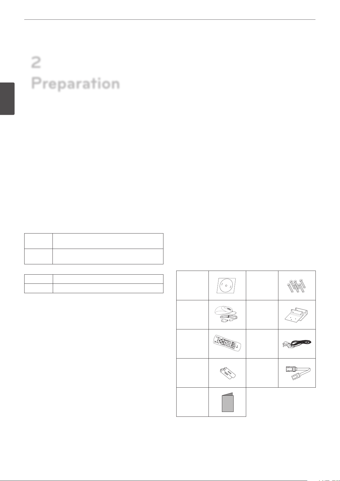
Accessories
CD (Software
and Owner's
Manual)
Mouse
Remote
Control
AAA type
batteries
Simple
Manual
Screws
Rack Mount
Bracket
Power Plug
SATA cable(s)
Front Panel
LOGIN SEARCH SETUP VIEW CAM BACK REC
OSD PTZ FOCUS+IRIS+
INFO ALM.OFFFOCUS -IRIS -
LOG TEXT OFFSET CLEAR
COPY MARK MOVE TOUR
1234
5678
13 14 15 16
9 10/0 11 12
OK
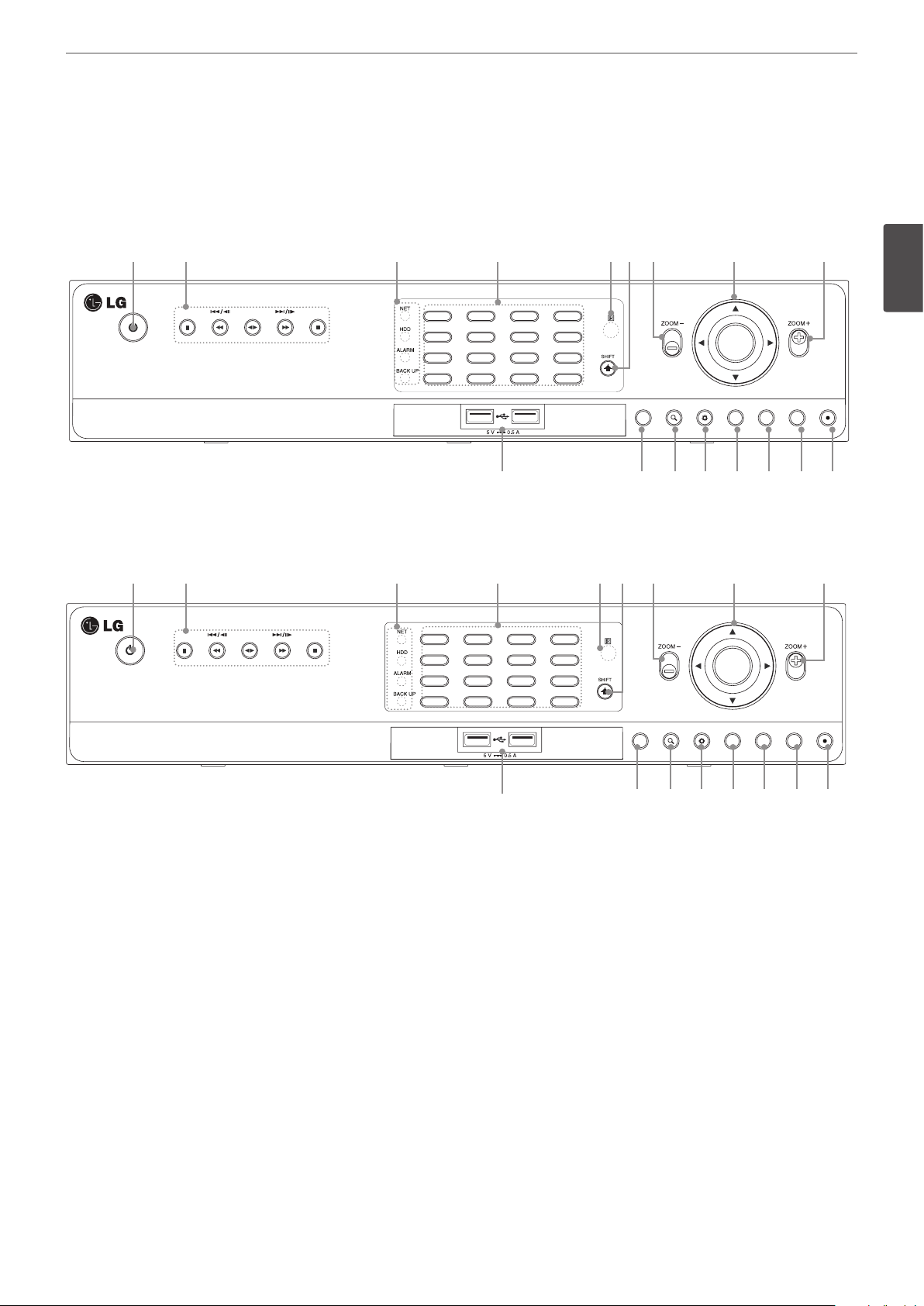
Front of the LRD5160 series
a b c d e f g h g
Preparation
9
Front of the LRD5080 series
a b c d e f g h g
OSD PTZ FOCUS+IRIS+
1234
INFO ALM.OFFFOCUS -IRIS -
5678
LOG TEXT OFFSET CLEAR
9 10/0 11 12
COPY MARK MOVE TOUR
13 14 15 16
i j k l m n o p
OSD PTZFOCUS+IRIS+
INFO ALM.OFFFOCUS -IRIS -
LOG TEXT OFF SET CLEAR
COPY
21234
5678
0
9
MARK MOVE TOUR
2
Preparation
OK
LOGIN SEARCH SETUP VIEW CAM BACK REC
OK
LOGIN SEARCH SETUP VIEW CAM BACK REC
a 1
b
(Power): Turns DVR on or off. Press and hold for more than 2 seconds to turn on or off.
Playback Control Buttons
•M: Pauses playback.
•
c, C/aM
•
•
: Playback or reverse playback of recorded images.
ad
v, V/Md
: Searches the recorded images in reverse or skips the recorded images.
: Forward searches the recorded images or skips the recorded images.
•Z: Stops playback.
Indicator
c
• NET: Blinks when the network is connected.
• HDD: Lights when the HDD is accessed.
• ALARM: Lights when the alarm out is in progress.
• BACK UP: Lights when the data back up is in progress.
i j k l m n o p

10
2
Preparation
Preparation
Channel Buttons: You can input a number with channel buttons. You can also use the channel buttons for sub-function with SHIFT
d
button (11 to 16 buttons of 8 channel DVR are used for sub-function without SHIFT button.).
You should press the OK button after input the channel number when you select the applicable channel.
• The LED in the button indicates the status as follows:
- Off: The current status is for live mode.
- Red: Recording mode.
- Blinks when an event occurs.
• Sub-functions
Button number Function Description
1 OSD Accesses or minimizes the System Control Bar (OSD).
2 PTZ Switches this unit to PTZ mode to control the connected PTZ camera.
3/7
4/8 IRIS - / IRIS + Adjust iris position.
5 INFO Displays the system information.
6 ALM.OFF
9 LOG Displays the System Log List.
10 TEXT OFF Displays or disappears the text information if the recording data includes text data.
11 SET Registers the PTZ camera’s preset position.
12 CLEAR Deletes a memorized preset position.
13 COPY Displays the export menu.
14 MARK Sets the mark point for recording search.
15 MOVE Moves the camera to the preset position.
16 TOUR Tours all registered preset positions in the camera.
FOCUS -
/ FOCUS +
Adjusts focus position.
Cancels alarm activation and returns the system to the condition before the alarm was
activated.
Remote Sensor: Point the remote control here.
e
SHIFT button: If you use the Sub-function of the channel button, the button is activated.
f
ZOOM + / -: Zooms in/out on playback window.
g
Arrow and OK Buttons
h
•
wsad
• OK: Confirms menu selections.
USB Port: Connects an external USB device for backup or playback.
i
LOG-IN: Displays the User Log-In dialog box or logs out.
j
SEARCH: Displays the search menu.
k
SETUP: Displays the setup menu.
l
VIEW: Displays the split mode menu for MAIN Monitor and SPOT Monitor.
m
CAM: Displays the Monitor menu to set the first camera channel.
n
BACK: Exits the menu or returns to the previous screen.
o
REC: Starts or stops instant recording.
p
: Select or move between the menu options.
Rear Panel
LOOP
OUT
VIDEO
INPUT
100 - 240 V ~ 50 / 60 Hz
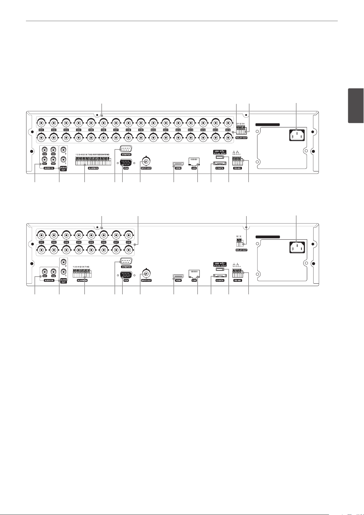
Rear of the LRD5160 series
VIDEO
INPUT
LOOP
OUT
e f g h i j k l m n o
a b c d
100 - 240 V ~ 50 / 60 Hz
Preparation
11
2
Preparation
Rear of the LRD5080 series
a b c d
VIDEO
INPUT
100 - 240 V ~ 50 / 60 Hz
LOOP
OUT
e f g h i j k l m n o
VIDEO INPUT: Connect the camera’s video output to these BNC connectors.
a
LOOP OUT: The signal from VIDEO INPUT connector is looped out to this connector.
b
RELAY-OUT Terminals: Output terminals for alarm (relay) signal.
c
Power Cord Inlet (AC IN): Connect the power plug.
d
AUDIO IN: Connect the audio output of an external device.
e
AUDIO OUT 1 / 2: Connect to an active speaker with a built-in amplifier.
f
ALARM-IN Terminals: Input terminals for alarm (relay) signal.
g
ATM/POS: Used to connect to a ATM/POS device.
h
VGA: Connect a VGA monitor.
i
SPOT-OUT (BNC Type Connector): Connect to spot monitor or display device.
j
HDMI: Connect to monitor or display device with HDMI inputs. (Interface for digital audio and video)
k
LAN Ports: Connect the ethernet 10/100/1000 Mbps network cable for controlling this unit via a PC network.
l
E-SATA: Connect the external SATA device.
m
USB Port: Connect an optional extension USB device.
n
RS-485 Terminals: Connect RS-485 compatible cameras.
o
Preparation
12
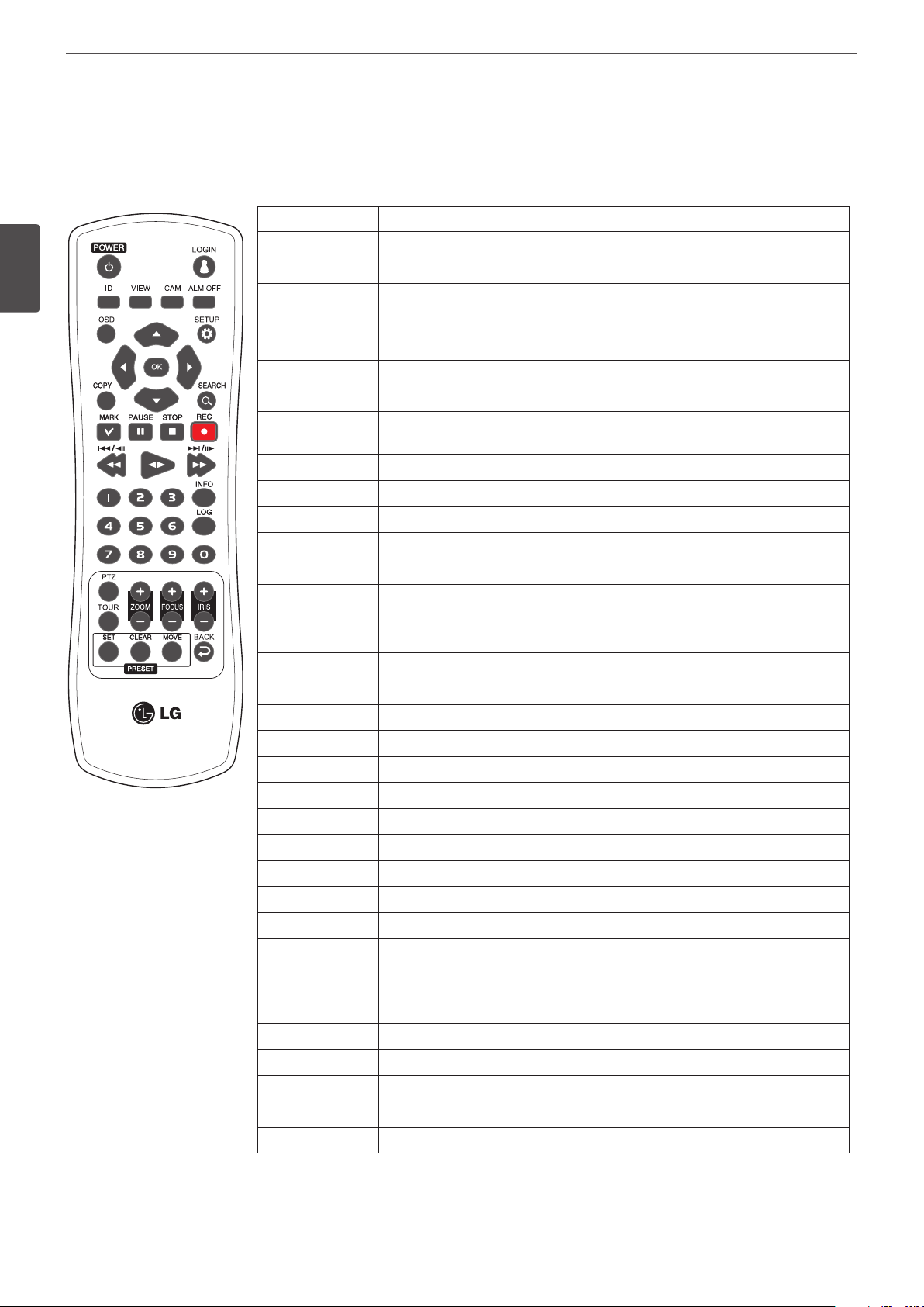
Remote Control
2
Preparation
Button Description
POWER (1)
LOGIN
ID
VIEW
CAM
ALM.OFF
OSD
SETUP
wsad
OK
COPY
SEARCH
MARK
PAUSE (M)
STOP (Z)
REC (X)
c, C/aM
ad
v, V/Md
Number Buttons
INFO
LOG
PTZ
TOUR
ZOOM + / -
FOCUS + / -
IRIS + / -
SET
CLEAR
MOVE
BACK
Turns DVR on or off.
Displays the User Log-In dialog box or logs out.
Set the appropriate DVR system ID to operate via the IR Remote Controller when
using the multiple DVR. Press the ID button then press the number button within
2 seconds to select the system ID of the DVR. If you set the system ID to “0”, you
can control multiple DVR at the same time.
Displays the split mode menu for MAIN Monitor and SPOT Monitor.
Displays the Monitor menu to set the first camera channel.
Cancels alarm activation and returns the system to the condition before the alarm
was activated.
Accesses or minimizes the system control bar.
Displays the setup menu.
Selects or moves between the menu options.
Confirms menu selections.
Copies the recording data to an external device.
Displays the search menu.
Sets the mark point for recording search. You can set the mark point during the
single or multi channel playback of recorded data.
Pauses playback.
Stops playback.
Starts or stops recording.
Searches the recorded images in reverse or skips the recorded images.
Playback or reverse playback of recorded images.
Forward searches the recorded images or skips the recorded images.
Selects the PTZ preset number, ID or channel.
Displays the system information window.
Displays the System Log List window.
Switches this unit to PTZ mode to control the connected PTZ camera.
Tours all registered preset positions in the camera.
Zooms in/out on the playback window.
If you press ZOOM(+) button during viewing a live channel in full screen mode or
playing back a channel in full screen mode, the digital zoom function is activated.
Adjusts the focus of a camera.
Adjusts the iris of a camera.
Registers the PTZ camera’s preset positions.
Deletes a memorized preset position.
Moves the camera to the preset position.
Exits the menu or returns to the previous screen.
3
Installation
Connections
Installation
13
Precautions
• Depending on the camera and other equipment there are various ways to connect the unit. Please refer to the camera manual or manuals
for other devices as necessary for additional connection information.
• Be sure to switch off the camera before installation and connection.
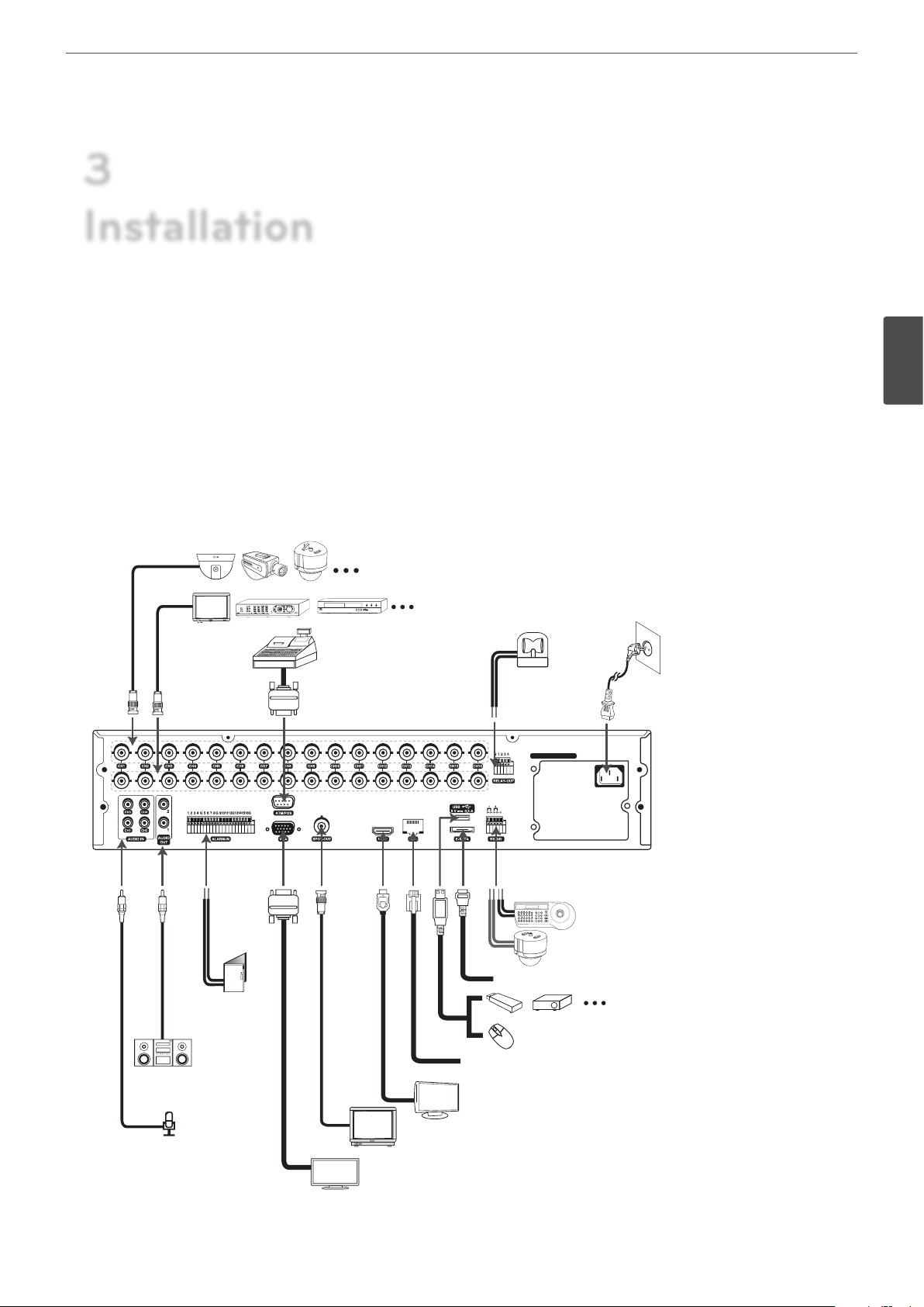
Basic Connection Overview
Connect the coaxial-type cameras
Connect the Monitor, DVR, VCR, or others.
Connect ATM/
POS unit.
VIDEO
INPUT
LOOP
OUT
Connect the
alarm (relay).
100 - 240 V ~ 50 / 60 Hz
Connect power
cord.
3
Installation
Connect audio
amplifier.
Connect audio
(line input).
Connect
alarm
sensors.
Connect PTZ cameras,
DVRs or keypads (optional).
Connect the external SATA device.
Connect an external USB device for
backup or playback.
Connect a mouse device.
Connect network cable for client control.
Connect HDMI type monitor (MAIN).
Connect BNC type monitor (SPOT).
Connect VGA monitor.
14
100 - 240 V ~ 50 / 60 Hz
100 - 240 V ~ 50 / 60 Hz
100 - 240 V ~ 50 / 60 Hz
100 - 240 V ~ 50 / 60 Hz
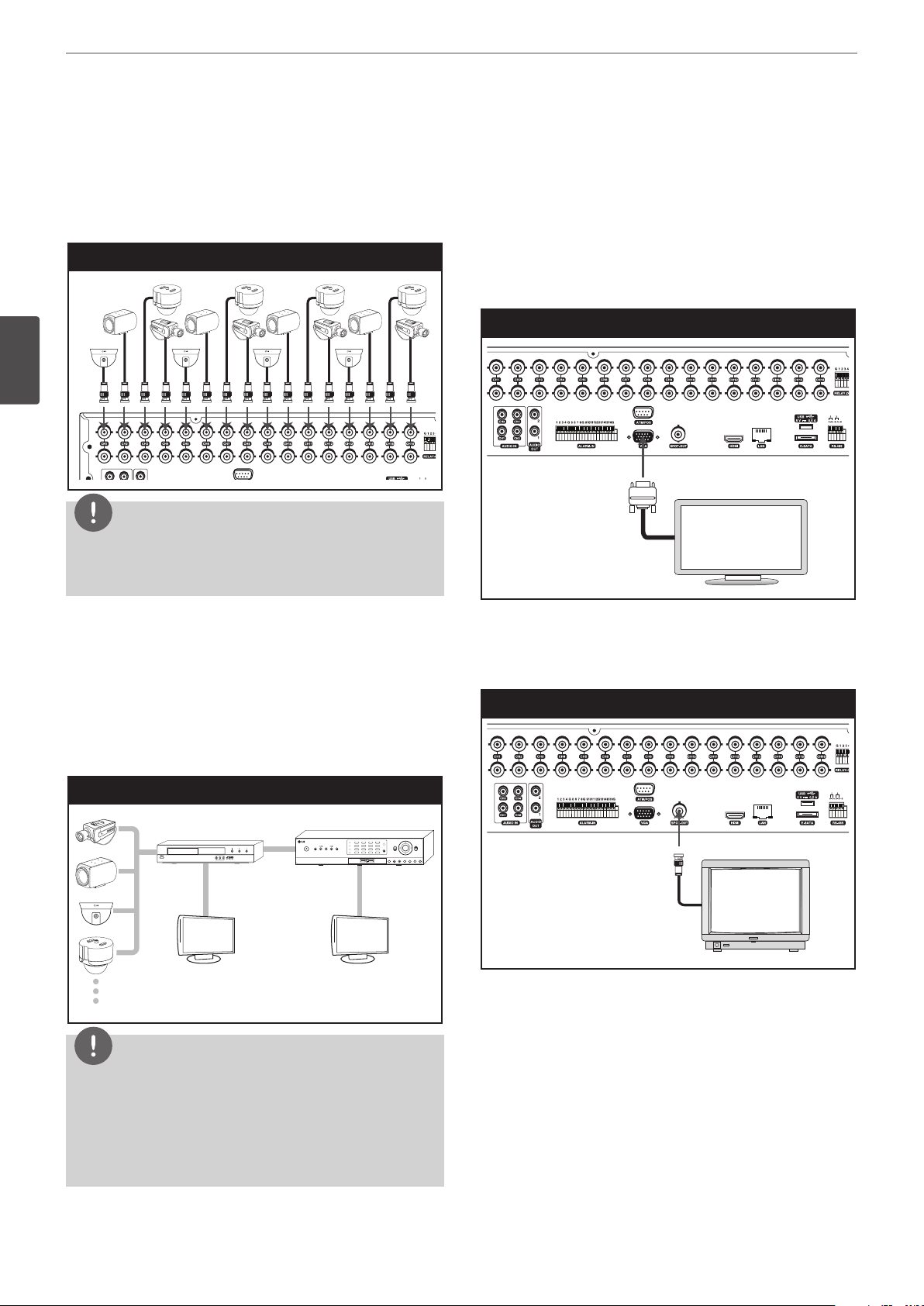
Installation
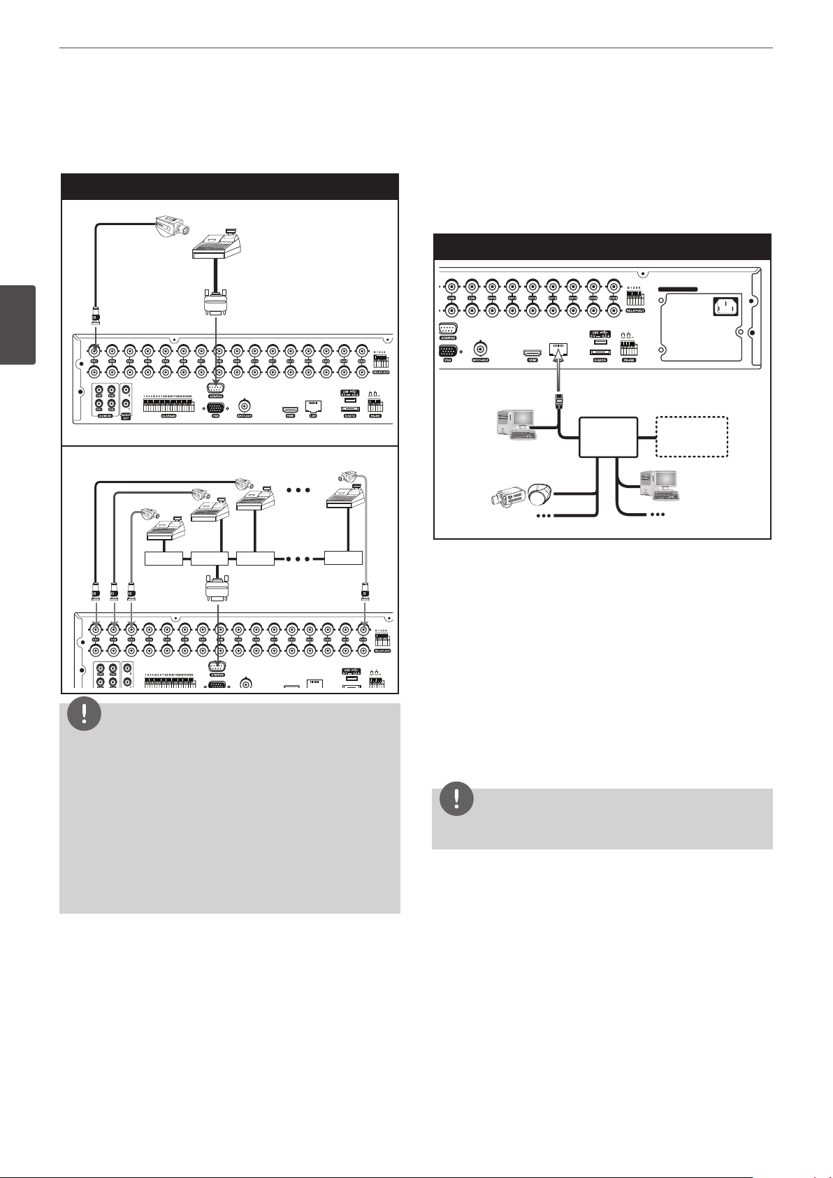
Connecting Camera
Connect the video output of your camera to the unit, using a
standard 75 Ω video coaxial cable with BNC connector.
LOOF OUT connector passes the video signal from VIDEO INPUT
connector to connect to other device.
Camera connection
3
Installation
VIDEO
INPUT
LOOP
OUT
NOTE
If the distance between the camera and DVR is too long, the noise
may be generated. In this case, we recommend you to ground
DVR’s power and not to ground camera’s power.
Connecting Display device
This unit can be output simultaneously from the HDMI, VGA and
SPOT OUT jack. The video signal connection between the DVR and
the monitor.
VGA Monitor connection
Connect the VGA jacks on the rear of the unit to the corresponding
input jacks on the TV or monitor using the VGA cable.
VGA Monitor connection
O
T
Connecting the video distributor
Connect the video signal of the camera to the input connector of
the video distributor using a 75 Ω video coaxial cable with BNC
connector. Connect the video output of the video distributer to the
VIDEO INPUT connector of DVR using a using a 75 Ω video coaxial
cable with BNC connector. Connect your monitor to the video
output connector of the video distributor.
Connecting the video distributor
Video distributor
Monitor Monitor
NOTE
DVR
OK
SPOT Monitor connection
Connect the unit to the SPOT monitor using 75 Ω video coaxial
cables with BNC connector.
SPOT Monitor connection
O
T
• If the cable’s length is too long, DVR’s parts may be damaged
due to an external static electricity. Before connecting the
video cable, touch the end of the cable to DVR’s case to avoid
the risk of static buildup.
• Please check the images via a monitor after installation of the
video distributor.
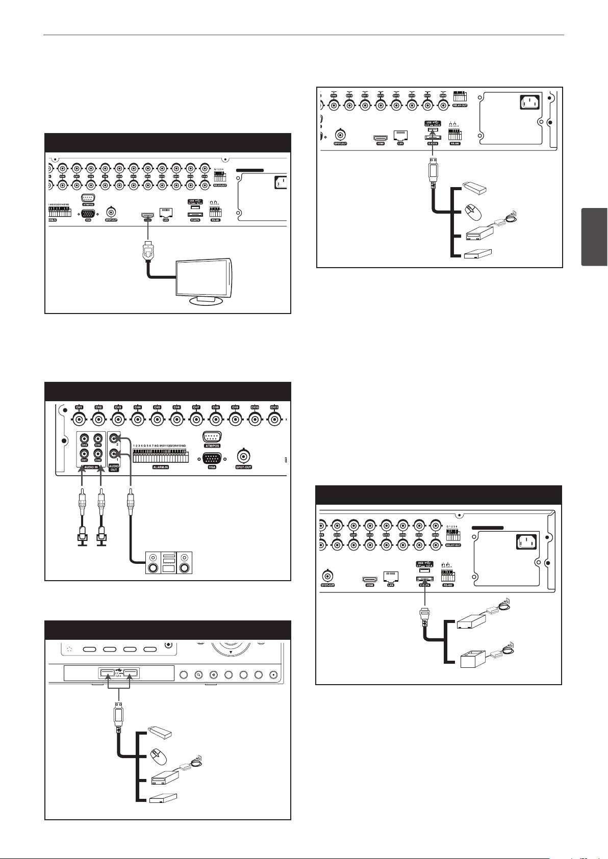
HDMI Monitor connection
100 - 240 V ~ 50 / 60 Hz
100 - 240 V ~ 50 / 60 Hz
VIDEO
INPUT
100 - 240 V ~ 50 / 60 Hz
1
OSDNET
HDD
ALARM
2
PTZ3FOCUS+4IRIS+
SHIFT
5
INFO6ALM.OFF7FOCUS -8IRIS -
9
LOG
10/0
TEXT OFF11SET12CLEAR
OK
100 - 240 V ~ 50 / 60 Hz
1
OSDNET
HDD
ALARM
BACK UP
2
PTZ3FOCUS+4IRIS+
SHIFT
5
INFO6ALM.OFF7FOCUS -8IRIS -
9
LOG
10/0
TEXT OFF11SET12CLEAR
13
COPY14MARK15MOVE16TOUR
OK
LOGIN SEARCH SETUP VIEWCAM BACK REC
Connect the unit to the HDMI monitor using a HDMI cable (Type A,
High Speed HDMITM Cable).
HDMI Monitor connection
100 - 240 V ~ 50 / 60 Hz
MAIN
Connecting Audio device
Connect the AUDIO OUT jacks on the unit to the mono audio in
jacks on your audio device.
Microphone and Speaker connection
LOOP
OUT
USB Memory device
Insert the memory device into the USB port. The system
automatically recognizes the device. The system software can be
easily upgraded using a USB memory device.
USB External device
Connect the external device to the USB port.
(Example: External HDD or other external storage.)
Mouse
Connect the USB mouse to operate the functions of the DVR.
Installation
15
3
Installation
Connecting USB device
USB device connection
BACK UP
COPY14MARK15MOVE16TOUR
13
LOGIN SEARCH SETUP VIEWCAM BACK REC
Connecting E-SATA device
You can use E-SATA storage for data back-up or recording.
E-SATA device connection
100 - 240 V ~ 50 / 60 Hz
16
100 - 240 V ~ 50 / 60 Hz
LOOP
OUT
VIDEO
INPUT
100 - 240 V ~ 50 / 60 Hz
100 - 240 V ~ 50 / 60 Hz
Installation
Connecting ATM/POS
Connect the ATM/POS unit to the ATM/POS port.
ATM/POS device connection
VIDEO
3
Installation
INPUT
LOOP
OUT
Connecting Network
You can control and monitor the system via network. With
the remote control (monitoring), you can change the system
configuration or monitor the image via network. After the
installation, check the network settings for the remote control and
monitoring work.
Network connection
100 - 240 V ~ 50 / 60 Hz
Broadband
Router
Router
Broadband
Service
Service
LAN connection
Connect the LAN port to an available 10/100/1000 base-T port with
a straight ethernet cable (not supplied). The NET indicator on the
VIDEO
INPUT
LOOP
OUT
NOTE
• The following device has been tested and compatibility is
ensured. When you use the multiple ATM/POS device, use the
recommended device.
- AVE Products
› VSI-PRO: Video serial interface
› Regcom: RS-485 networker
› Hydra: RS-485 to RS-232 converter
• The installation and connection work should be done by
qualified service personnel or system installers and should be
conformed to all local codes.
front panel will be lit.
Automatic network configuration
The DVR can automatically obtain and configure the network
interface via DHCP.
Manually configure network
The DVR may be manually configured by assigning an IP address,
subnet mask, gateway and DNS.
NOTE
This unit can be supported IPv4 and IPv6 network.
Installation
100 - 240 V ~ 50 / 60 Hz
100 - 240 V ~ 50 / 60 Hz
17
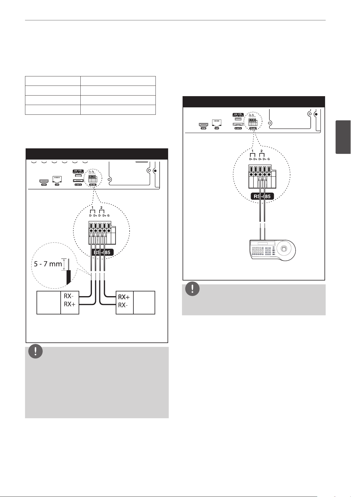
Connecting RS-485 device
This DVR has two data terminals. Use this port to connect PTZ
cameras, DVRs or keypads (optional).
RS-485 Terminal Description
D - (DATA -) Data Transmission/Reception
D + (DATA +) Data Transmission/Reception
GND Shield
Connecting the PTZ device
Connecting the PTZ serial communication lines to the
RS-485 terminal.
PTZ device connection
Connecting LKD1000 controller
Connect the LKD1000 controller to control the DVR. (Refer to the
manuals of the LKD1000 controller for more details.) The LKD1000
controller has to be connected to the 2 (DATA 2) port as shown
illustration. If you connect the LKD1000 controller to the 1 (DATA 1)
port, the LKD1000 controller will not be activated.
LKD1000 controller connection
3
Installation
PTZ units
(RS-485 type)
PTZ units
(RS-485 type)
NOTE
• When connecting lines, connect the “D -” of the DVR to “RX -”
of the PTZ unit and “D +” of the DVR to “RX +” of the PTZ unit
correctly.
• Recommended initial data are 9600 Baud Rate, 8 Data bits,
1 Stop bit and No parity.
• When connecting PTZ cameras to DVRs it is necessary to set
the setup menu for this unit according to the RS-485 settings
of the camera and DVRs.
TX+TX-
LKD1000 Controller
NOTE
Do not connect a PTZ camera and LKD1000 controller to the D1 or
D2 port at the same time. It may cause a malfunction.
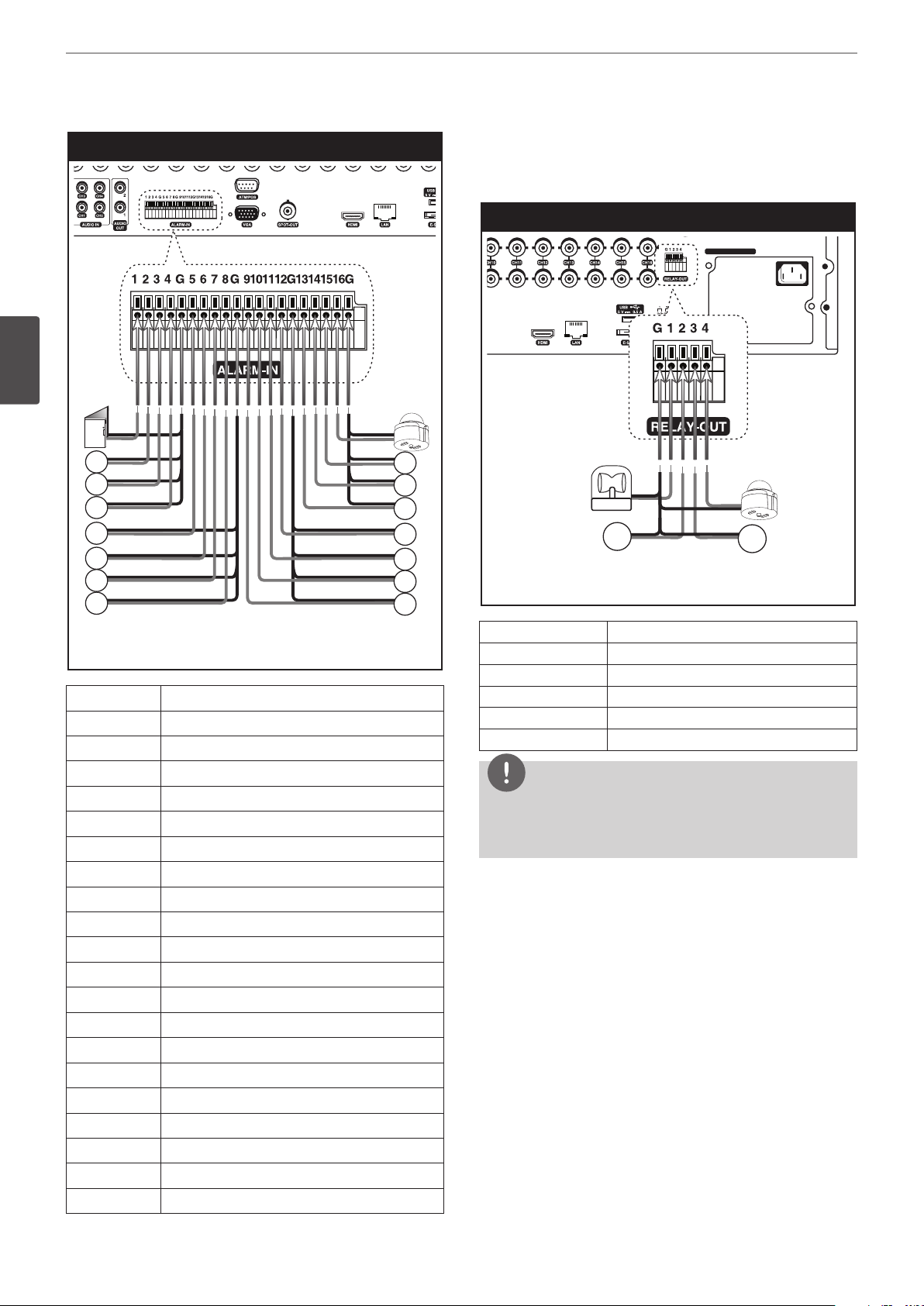
Connecting Alarm Input and Alarm Output
Alarm terminals are used to connect the alarm devices such as
sensors, door switches, etc.
Alarm Input
You can connect up to 16 alarm sensors (LRD5080: 8 alarm sensors).
Each alarm sensor should be connected with G (GND). The signal
state is adjustable to N/O (Normal Open) or N/C (Normal Close)
through the setup menu.
18
100 - 240 V ~ 50 / 60 Hz
Installation
3
Installation
Sensor input connection
Alarm Output
Connect the alarm device to the alarm output. Alarm signal outputs
when an event occur.
Alarm output connection
100 - 240 V ~ 50 / 60 Hz
Alarm device
Alarm device
Alarm sensor Alarm sensor
Terminal No. Description
1 Sensor Input 1
2 Sensor Input 2
3 Sensor Input 3
4 Sensor Input 4
G Ground
5 Sensor Input 5
6 Sensor Input 6
7 Sensor Input 7
8 Sensor Input 8
G Ground
9 Sensor Input 9
10 Sensor Input 10
11 Sensor Input 11
12 Sensor Input 12
G Ground
13 Sensor Input 13
14 Sensor Input 14
15 Sensor Input 15
16 Sensor Input 16
G Ground
Terminal No. Description
G Ground
1 Alarm Output 1
2 Alarm Output 2
3 Alarm Output 3
4 Alarm Output 4
NOTE
The internal switching relays are rated for 0.3 A at 125 V AC or 1 A
at 30 V DC. If the electric current is higher than that the unit can
be damaged.
Installation
19
HDD INSTALLATION
Note for Hard Disk Drive
The internal hard disk drive (HDD) is a fragile piece of equipment.
Please follow the guidelines below when using the DVR to protect
against possible HDD failure. We recommend that you back up your
important recordings onto an external backup device in order to
prevent accidental loss.
Make sure that the power is turned OFF when attaching or
removing the HDD.
• Do not move the DVR while the power is on.
• Do not use the DVR in excessively hot or humid places, or in
places that may be subject to sudden changes in temperature.
Sudden changes in temperature can cause condensation to
form inside the DVR. This can be a cause of HDD failure.
• While the DVR is switched on, do not unplug from the wall
socket or switch the electricity off from the breaker switch.
• If there’s a power failure while the DVR is on, some data on the
HDD may be lost.
• Do not drop the HDD. Also do not put the metallic object such
as coins or screwdrivers into the HDD tray.
• When a power failure occurs during recording, avoid adding,
replacing or transporting the HDD as the recorded data may be
erased. In this case, turn the power back on to boot up the unit
normally with the HDD that was being used at the time of the
power failure attached. Then add, replace, or transport the HDD.
• The HDD is very delicate. Handle the HDD with care and follow
the precautions below because even a tiny shock may damage
the internal components of the HDD.
- Do not place the HDD on the desk or table directly. Put a
thick cushion under the HDD because even a small shock
may damage the internal components of the HDD.
- Do not use an electric screwdriver. Vibrations and shocks
caused by an electric screwdriver may damage the internal
components of the HDD.
- When replacing the HDD, do not knock the HDD with other
components such as another HDD and the HDD tray.
- Do not knock the HDD with tools such as a driver when
replacing the HDD.
• Protect the hard disk drives from static electricity.
7. Connect the SATA cable to the SATA connector on the main
board.
8. Assemble the top case.
9. Fix the screws.
10. When you turn the power of the unit on, the new HDD is
detected and formatted automatically.
Replacing the Hard Disk Drive
Turn the power of the unit off and detach the power plug from the
outlet.
1. Follow steps 1 to 2 described in “Installing the Hard Disk Drive”.
2. Remove the connector from the HDD.
3. Remove the screws from the hard disk drive on the left/right
side of the hard disk mounting bracket.
4. Remove the HDD from the hard disk mounting bracket.
5. Install the new HDD.
6. After replacing the hard disk drive, insert the power plug into
the outlet and turn the power of the unit on. The new HDD is
detected and formatted automatically.
automatically.
NOTE
Do not use an electric screwdriver to fix them.
Recommended HDD
For the latest recommended HDD list, please visit
http://www.lgecommercial.com
NOTE
If you do not use the recommended HDD, the system may not be
operated normally.
3
Installation
Installing the Hard Disk Drive
You can install up to 4 HDDs.
Improper installation or setup may disturb HDD recognition or
normal product operation. So you should consult with an expert
from the store where the product was purchased.
1. Detach the top case by sliding it after removing the screws.
2. Remove the screws and detach the hard disk mounting brackets
from the unit.
3. Attach the HDD onto the hard disk mounting brackets with four
screws.
4. Attach the hard disk mounting brackets with the screws.
5. Connect the HDD power cable to the HDD.
6. Connect the SATA cable to the HDD.
20
Installation
System Operation
1. Turn on the unit. System booting will commence. The LG logo
image will be displayed on the main monitor during the system
booting.
2. When the booting is completed the live window will be
displayed. Click the icon on the system control bar or press
the LOGIN button on the remote control to display the log-in
window.
3. Select a user name by using the mouse or arrow and the OK
3
Installation
button on the remote control or front panel. For the first time,
you can select the ADMINISTRATOR user name only. You can
register a new user with various access rights using the user
setup menu.
4. Enter the password by using the virtual keyboard. (Note that the
default administrator password is “000000”.)
5. Click the [OK] icon.
You can see the live screen and operate the system.
NOTE
• This DVR is based on a VGA monitor using OSD. We
recommend you to using the VGA monitor with this unit. If
you use a composite monitor, the OSD quality may be low to
read it.
• If the DVR is turned off accidently and then turned on again,
the DVR may take a long time to be rebooted.
System Shutdown
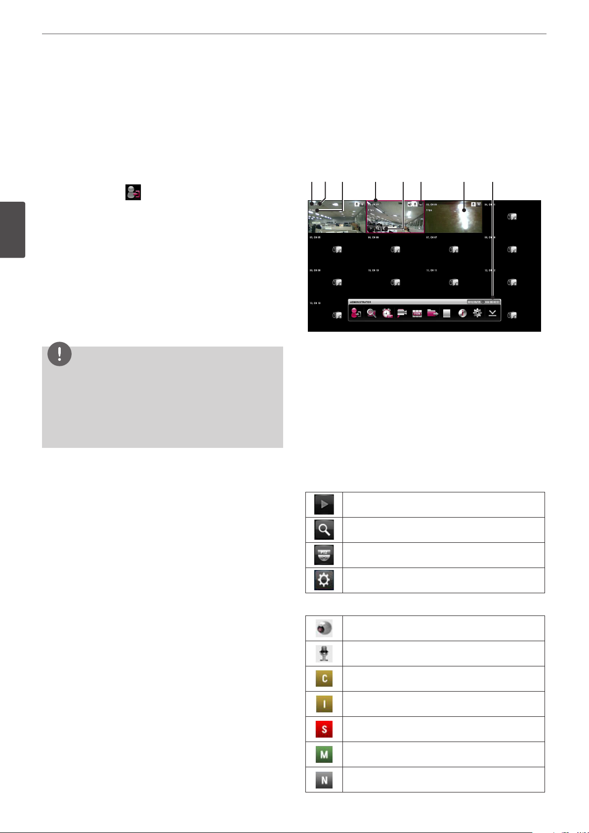
General Explanation of the Live Screen on the Main Monitor
Main Monitor Screen
a b c d e f g h
Channel Number
a
Displays the channel number.
Channel Name
b
Displays the edited channel name.
Channel FPS
c
Displays the channel FPS value.
Selected Channel
d
Displays the selected channel with red box.
Quick Buttons
e
The Quick Buttons will appear when the mouse is moved to
the camera's live screen. You can use the following functions by
clicking it for the selected channel.
You can use the playback function.
1. First, you must stop playback and exit the setup menu. In
playback, press STOP.
2. Press and hold 1 (POWER) button until the beep sounds and
the logout window will be displayed.
3. Enter the password by using the virtual keyboard.
4. Click the [OK] icon. The system will shutdown.
You can use the digital zoom function.
You can control the PTZ Camera. (optional)
You can use the video adjustment (Brightness,
Contrast, Color) function. (Analog Channel Only)
Camera Status Icon
f
Displays the PTZ camera status.
Displays the input audio status.
Gold “C” indicates continuous recording.
Gold “I” indicates Instant recording.
Red “S” indicates sensor triggered recording.
Green “M” indicates motion detection recording.
Gray “N” indicates the channel is not being recorded.
Installation
21
Violet “T” indicates text event recording.
Live Screen
g
Displays the current surveillance live screen.
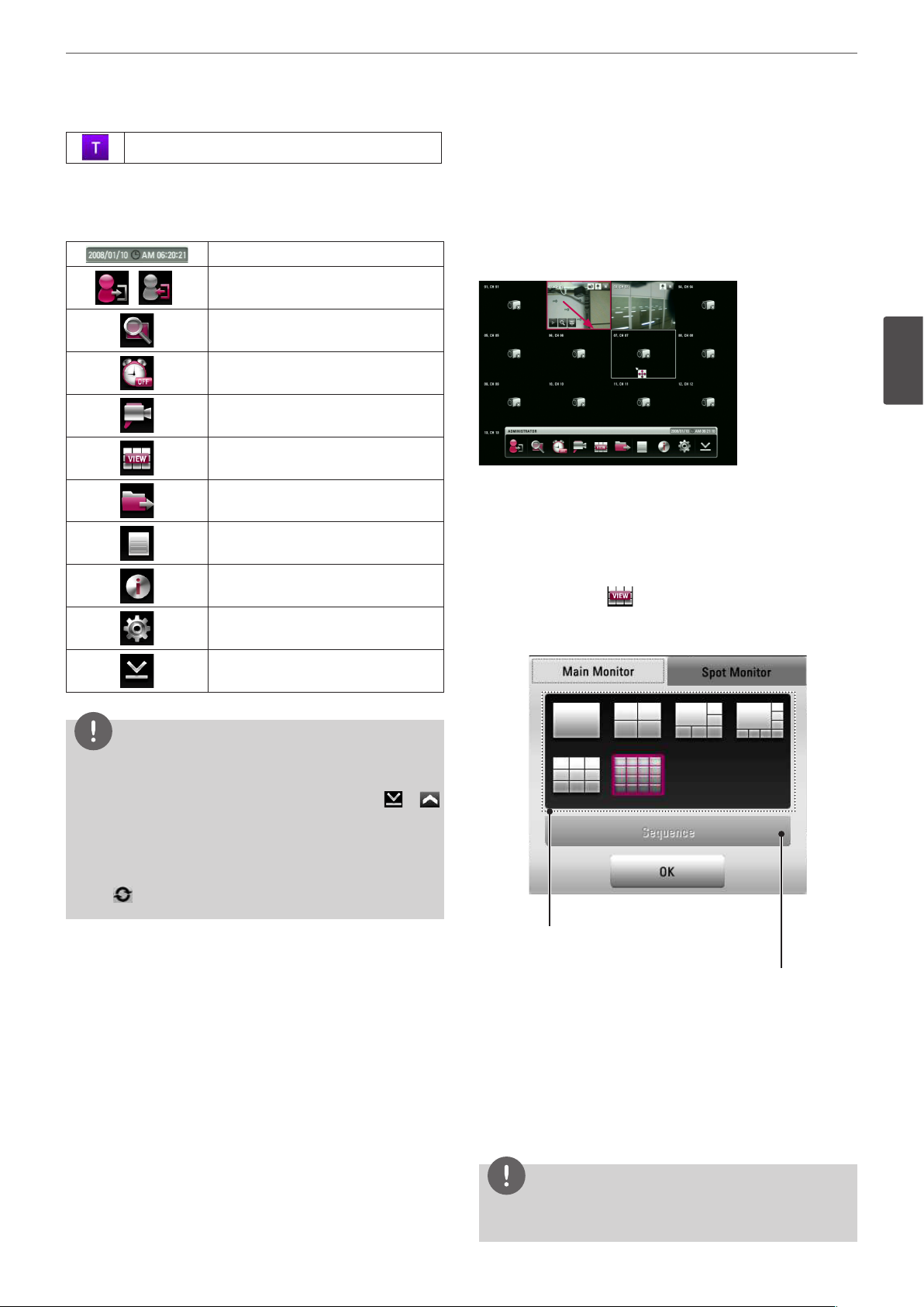
System Control Bar
h
Displays date and time.
( )
Login (Logout) : Display the User Log-In
dialog box or logs out.
Search: Displays the search menu.
Alarm Off: Turns the alarm off.
Camera: Displays the Monitor menu to
set the first camera channel.
Split mode: Displays the menu for
selecting the screen division.
Video Export: Displays the export menu.
System Log: Displays the system log list
window.
System Information: Displays the system
information window.
Setup: Displays the setup menu.
Moving the Channel's Position
You can change the camera channel's position in a split screen of
the Main Monitor.
1. Select a desired channel by clicking the left button of the
mouse.
2. Drag and drop it to a desired location and the channel's position
will be changed.
3
Installation
Selecting the Main Monitor screen mode
You can select the live screen mode to display a full, 4-split, 6-split,
8-split, 9-split, 16-split, 17-split or 25-split screens on the main
monitor.
1. Press VIEW or click icon in the system control bar.
2. Select [Main Monitor].
3. Select a screen mode.
Minimizes the System Control Bar.
NOTE
• To display / minimize the system control bar
To display or minimize System Control Bar, press OSD after
pressing the SHIFT button on the front panel or click
in the System Control Bar.
• You can also use the system control's options by clicking the
right button of the mouse on the Main Monitor screen.
• While the main monitor is performing the sequence mode,
the
mark is displayed on the system control bar.
or
Screen split mode
Sequence mode
• Full Screen Mode: You can view the live window in full
screen mode.
• 4, 9, 16, 1+5, 1+7 Split Mode: Displays selected split screens
on the main monitor.
• Sequence: You can view all the channels in sequence. You
cannot use sequence mode with the 16 split (LRD5080
series: 1+7 and 9 split).
4. Select [OK] and press OK to confirm your selection.
NOTE
To display the screen you want to watch in full screen mode,
double click the desired channel.
 Loading...