

LG LPT-EP553OS User Manual
Dome Camera
Owner’s Manual
MODEL: LPT-EP551OS / LPT-EP553OS
LPT-EI551OS / LPT-EI553OS
Before installing and using the camera, please read this owner's
manual carefully and retain for future reference.
LPT-EP553OS_ATURALI_ENG.qxp:LPT-EP553PS_ATURALI_ENG 2008.4.29 5:37 PM Page 1
2
This lightning flash with arrowhead symbol
within an equilateral triangle is intended to
alert the user to the presence of uninsulated dangerous voltage within the product’s
enclosure that may be of sufficient magnitude to constitute a risk of electric shock to
persons.
The exclamation point within an equilateral
triangle is intended to alert the user to the
presence of important operating and maintenance (servicing) instructions in the literature accompanying the product.
FCC WARNING : This equipment may generate or
use radio frequency energy. Changes or modifications to this equipment may cause harmful interference unless the modifications are expressly
approved in the instruction manual. The user could
lose the authority to operate this equipment if an
unauthorized change or modification is made.
REGULATORY INFORMATION: FCC Part 15
This equipment has been tested and found to comply with the limits for a Class A digital device, pursuant to Part 15 of the FCC Rules. These limits are
designed to provide reasonable protection against
harmful interference when the equipment is operated in a commercial environment.
This equipment generates, uses, and can radiate
radio frequency energy and, if not installed and used
in accordance with the instruction manual, may
cause harmful interference to radio communications.
Operation of this equipment in a residential area is
likely to cause harmful interference in which case
the user will be required to correct the interference
at his own expense.
• A suitable conduit entries, knock-outs or glands
shall be provided in the cable entries of this product in the end user.
• Caution: Danger of explosion if battery is incorrectly replaced. Replaced only with the same or
equivalent type recommended by the manufacturer. Dispose of used batteries according to the
manufacturer ’s instructions.
• Holes in metal,,through which insulated wires
pass,shall have smooth well rounded surfaces or
shall be provided with brushings.
Warning: Do not install this equipment in a confined
space such as a bookcase or similar unit.
Warning: Wiring methods shall be in accordance
with the National Electric Code, ANSI/NFPA 70.
Warning: This is a class A product. In a domestic
environment this product may cause radio interference in which case the user may be required to take
adequate measures.
Warning: To reduce a risk of fire or electric shock, do
not expose this product to rain or moisture.
Caution: This installation should be made by a qualified service person and should conform to all local
codes.
Caution: To avoid electrical shock, do not open the
cabinet. Refer servicing to qualified personnel only.
Caution: The apparatus should not be exposed to
water (dripping or splashing) and no objects filled
with liquids, such as vases, should be placed on the
apparatus.
Disposal of your old appliance
1. When this crossed-out wheeled bin symbol is
attached to a product it means the product is
covered by the European Directive
2002/96/EC.
2. All electrical and electronic products should be
disposed of separately from the municipal
waste stream via designated collection facilities appointed by the government or the local
authorities.
3. The correct disposal of your old appliance will
help prevent potential negative consequences
for the environment and human health.
4. For more detailed information about disposal
of your old appliance, please contact your city
office, waste disposal service or the shop
where you purchased the product.
This product is manufactured to comply
with EMC Directive 2004/108/EC and Low
Voltage Directive 2006/95/EC.
European representative :
LG Electronics Service Europe
B.V.Veluwezoom 15, 1327 AE Almere,
The Netherlands (Tel : +31-036-547-8940)
CAUTION: TO REDUCE THE RISK
OF ELECTRIC SHOCK
DO NOT REMOVE COVER (OR BACK)
NO USER-SERVICEABLE PARTS INSIDE
REFER SERVICING TO QUALIFIED SERVICE
PERSONNEL.
CAUTION
RISK OF ELECTRIC SHOCK
DO NOT OPEN
LPT-EP553OS_ATURALI_ENG.qxp:LPT-EP553PS_ATURALI_ENG 2008.4.29 5:37 PM Page 2
3
Contents
Introduction . . . . . . . . . . . . . . . . . . . . . . . . . . . . . . .3
Contents . . . . . . . . . . . . . . . . . . . . . . . . . . . . . . . . . . .3
About Dome Camera . . . . . . . . . . . . . . . . . . . . . . . . .3
Features . . . . . . . . . . . . . . . . . . . . . . . . . . . . . . . . . . .3
Safety Precautions . . . . . . . . . . . . . . . . . . . . . . . . . . .5
Identification of Camera . . . . . . . . . . . . . . . . . . . . . . .6
Installation . . . . . . . . . . . . . . . . . . . . . . . . . . . . . . . .7
Precautions . . . . . . . . . . . . . . . . . . . . . . . . . . . . . . . . .7
Mounting the Camera . . . . . . . . . . . . . . . . . . . . . . . . .7
• Removing the Sponge . . . . . . . . . . . . . . . . . . . . . .7
• Ceiling mount . . . . . . . . . . . . . . . . . . . . . . . . . . . . .7
• Pendant mount . . . . . . . . . . . . . . . . . . . . . . . . . . . .8
• Wall mount . . . . . . . . . . . . . . . . . . . . . . . . . . . . . . .8
Setting the Switch . . . . . . . . . . . . . . . . . . . . . . . . . . . .9
• RS-485 Parameter Setup . . . . . . . . . . . . . . . . . . . .9
• Alarm Output Mode Setting . . . . . . . . . . . . . . . . .10
• Camera ID Setting . . . . . . . . . . . . . . . . . . . . . . . .10
Connections . . . . . . . . . . . . . . . . . . . . . . . . . . . . .13
Connection Preview . . . . . . . . . . . . . . . . . . . . . . . . .13
Precautions . . . . . . . . . . . . . . . . . . . . . . . . . . . . . . . .13
RS-485 Connection . . . . . . . . . . . . . . . . . . . . . . . . .13
ALARM IN Connections . . . . . . . . . . . . . . . . . . . . . .14
ALARM OUT Connections . . . . . . . . . . . . . . . . . . . .15
Data Port Connections . . . . . . . . . . . . . . . . . . . . . . .16
System Connection . . . . . . . . . . . . . . . . . . . . . . . . .17
Adapter Connections . . . . . . . . . . . . . . . . . . . . . . . .18
Setup Menu . . . . . . . . . . . . . . . . . . . . . . . . . . . . . .19
Setup Menu Overview . . . . . . . . . . . . . . . . . . . . . . .19
Setting Camera Menu . . . . . . . . . . . . . . . . . . . . . . .20
Camera Identification Setting . . . . . . . . . . . . . . . . . .21
Focus Settings . . . . . . . . . . . . . . . . . . . . . . . . . . . . .21
White Balance Control Settings . . . . . . . . . . . . . . . .23
Exposure Settings . . . . . . . . . . . . . . . . . . . . . . . . . .24
Auto Exposure Level Settings . . . . . . . . . . . . . . . . .27
Special Settings . . . . . . . . . . . . . . . . . . . . . . . . . . . .28
Motion Detection Setting . . . . . . . . . . . . . . . . . . . . .30
Function On-Screen Display Setting . . . . . . . . . . . .30
Privacy Masking Settings . . . . . . . . . . . . . . . . . . . . .31
Reference . . . . . . . . . . . . . . . . . . . . . . . . . . . . . . . .32
Specifications . . . . . . . . . . . . . . . . . . . . . . . . . . . . . .32
About Dome Camera
The dome cameras are designed for installation in an
indoor or outdoor video surveillance system.
The camera incorporates the digital signal processor,
pan/tilt mechanism, x27 zoom lens and RS-485 communication interface in a compact outdoor enclosure.
A newly developed 1/4" CCD makes the camera
suitable for use under extremely low illumination conditions as well as in daylight.
Setup menus allow the camera to perform surveillance tasks by such means as motion detection, digital flip, pattern-recording and privacy zones.
Features
x
High Sensitivity Support
The camera provides the high quality picture with
1/4" Super HAD CCD.
x
Preset Position
Preset position is the function to register camera
monitoring positions (preset positions) associated
with position numbers. By entering the position
numbers, you can move cameras to the preset
positions.
A maximum of 128 Preset Position is available.
The moving speed and holding time are
adjustable.
x
Preset Tour
You can tour all preset positions that has already
been registered.
x
Preset Group Tour
You can create a preset group using the preset
positions that has already been registered (maximum 9 groups) and you can tour the preset position within the group.
A preset group should have a maximum of 8 preset positions.
Introduction
LPT-EP553OS_ATURALI_ENG.qxp:LPT-EP553PS_ATURALI_ENG 5/8/08 3:41 PM Page 3

4
x
Pattern Function
A routine of manual operations can be stored for 8
minutes at the maximum and reproduced repetitively. The Panning, Tilting and Zoom controls are
available for recording the pattern.
Note: The available total time of pattern differs
depending on camera’s operation. When the time
is over, the pattern setup will automatically stop.
x
Privacy Mask
Privacy zone feature enables users to veil unwanted zones. This setting is used for masking
unwanted zones, hiding them from display on the
monitor screen. Up to 8 zones can be registered.
x
Auto Pan
The camera has an Auto Pan function that
enables to keep surveillance on every detail occurring around the specific area, which is preset to
watch in advance.
The camera can pan among the maximum 8
points you will set. The moving speed and holding
time are adjustable.
x
Auto Flip
When the camera is operated to tilt through the
90°, it can be watched the opposite side of the
locations by Auto Flip of a 180° horizontally.
x
Sophisticated Design
This is the surveillance camera that can fit any
indoor surroundings because it comes in the compact size and sophisticated design.
x
Zoom Lens & Auto Focus
Zooming is possible from 27 times (the optical
zoom limit), to a maximum of X12 times digital
zoom.
x
Sensor Linkage
The camera is capable of capturing a subject by
the focus of camera moving promptly toward the
subject at the rate of 240°/sec when the camera
works with a detector (magnetic, beam, infrared
rays), and a subject moving within a detection
area is captured by a detector.
x
Alarm In function (8 channels)
Alarm input signals are supplied from external
devices through the ALARM IN connector to turn
the camera to a preset position.
x
Alarm Out function (4 channels)
When alarm inputs are supplied via the alarm
input connector on the camera, the camera sends
output signals via the alarm output connector on
the camera.
x
Controls by General Controller
This camera can be controlled by RS-485.
Especially the camera has an excellent cost-saving effect because it can be controlled by the general RX point of contact signal.
x
Connects with the maximum 256 cameras
This camera can be utilized after being connected
with maximum 256 cameras.
Therefore, it is capable of performing an excellent
job in the large buildings or department stores.
x
Day & Night Function
This camera can be selected Color or Black &
White. You can set Color in the daytime and Black
& White at night due to the low illumination. (Filter
Conversion type)
x
DSS (Digital Slow Shutter) function
It is possible to highly sensitive surveillance
because of DSS(Digital Slow Shutter) function.
Note: During Auto Pan, Preset Tour, or Pattern
Record/Play, you can use only STOP key or
Joystick on the controller.
x
Power Supply
This camera must always be operated a AC 24V
Certified/Listed, class 2 power supply only.
x
Heat Pad
The heat pad is installed in this unit. If the unit’s
inside temperature is below than -1°C, the heat
pad is operated to rise the temperature.
LPT-EP553OS_ATURALI_ENG.qxp:LPT-EP553PS_ATURALI_ENG 2008.4.29 5:38 PM Page 4
5
Safety Precautions
x
Do not attempt to disassemble the camera
To prevent electric shock,do not remove screws or
covers. There are no user serviceable parts inside.
Ask a qualified service personnel for servicing.
x
Avoid the camera with direct sunlight
Do not aim the camera at bright objects.Whether
the camera is in use or not, never face it with
direct sunlight or other extremely bright objects.
Otherwise blooming or smear may be caused.
x
Handle the camera with care
Do not abuse the camera. Avoid striking, shaking,
etc. The camera could be damaged by improper
handling or storage.
x
Do not use strong solvents or detergents
Use a dry cloth to the camera when it is dirty. If it
is hard to remove the dirt on the camera, use a
mild detergent and wipe it gently.
x
Do not install this camera upside down
This camera is designed for mounting on the ceiling or wall.If you install this camera upside down,
for example, mounted on the floor, it may cause
malfunction.
x
Do not use the camera in such places as
shown below.
The lens may become cloudy due to condensation
if the camera is used under the following conditions.
- Rapid temperature fluctuation by switching an
air conditioner on and off.
- Rapid temperature fluctuation due to frequent
door opening and closing.
- Use in an environment where eyeglasses
become foggy.
- Use in a room filled with cigarette smoke or
dust.
If the lens becomes cloudy due to condensation,
remove the dome cover and wipe all moist surfaces with a soft cloth.
x
Before operating, please check proper temperature, humidity and power source ratings.
Use the camera under conditions where temperature is between -10 °C – +50 °C and humidity is
below 80%.
The input power source is AC 24V.
x
Consumables
Parts having contacts such as the lens-drive
motors,cooling fan built inside the camera are subject to wear with time. About replacement and
maintenance of such parts,please ask the nearest
service center.
LPT-EP553OS_ATURALI_ENG.qxp:LPT-EP553PS_ATURALI_ENG 2008.4.29 5:38 PM Page 5
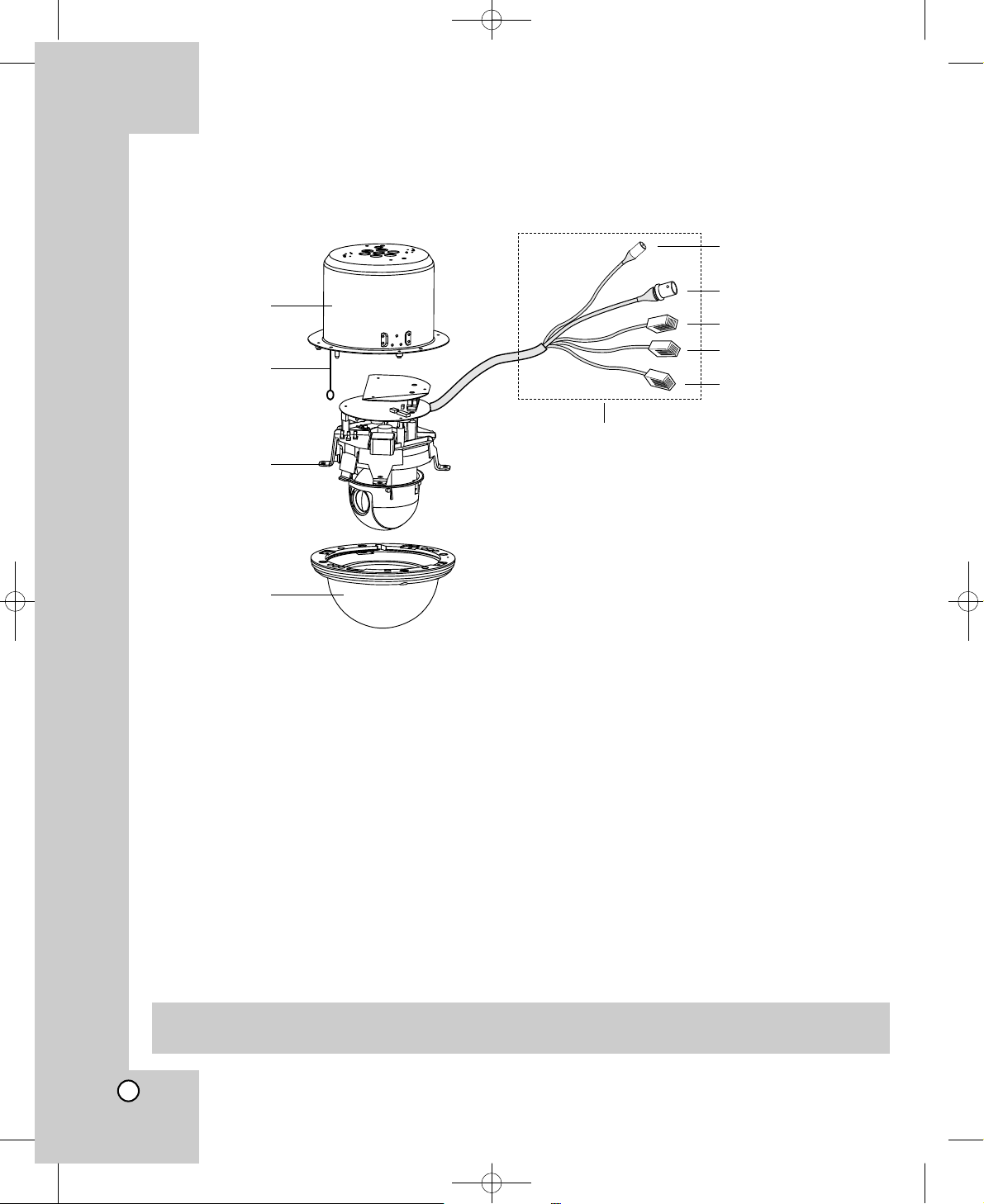
6
a Camera mounting bracket
The bracket is optional for surface installation.
b Fall Prevention Wire
Be sure to hook the fall prevention wire into an bracket.
Caution: When you fix the the dome cover to the dome camera body, you must insert the wire in the
dome camera body. If not, the wire may obstruct the camera’s moving.
c Dome camera body
d Dome cover
e Power cable (AC 24V)
f Video output cable with BNC connector
Connects with the video connector of the monitor.
g Data Communication Port (RJ45) - RS-485 and Alarm Input
h Data Communication Port (RJ45) - RS-485 and Alarm Input
i Data Communication Port (RJ45) - Alarm Output
Identification of Camera
a
b
c
d
e
f
g
h
i
“A”
“A”
Do not expose cable connection part to outdoor such as rain, moisture environment. It may cause
waterproof problem. But If you are indeed. Sealing them tightly.
LPT-EP553OS_ATURALI_ENG.qxp:LPT-EP553PS_ATURALI_ENG 2008.4.29 5:38 PM Page 6
7
Precautions
• The following steps of installation and connection
work should be done by qualified service personnel or system installers and should conform to all
local codes.
• Be sure to switch the camera off before installation
and connection.
• Do not install the camera near the air outlet of an
air conditioner.
• Do not touch the dome cover’s window.
Mounting the Camera
The figures show an example of the camera mounted
on a ceiling or wall with a locally procured bracket.
Refer to the instructions included with the bracket for
filling gaps and holes with waterproof material.
Note: The camera have not been evaluated for wall
or ceiling mounting.
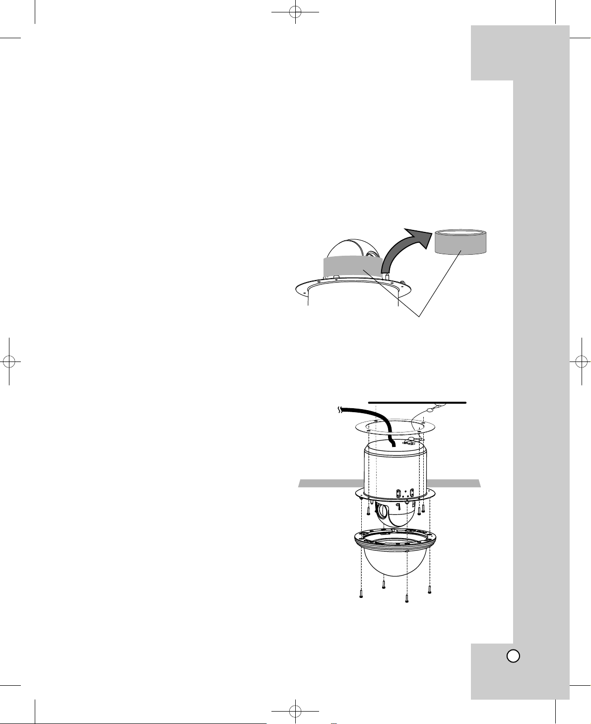
Removing the Sponge
Before mounting the camera, remove the sponge for
camera protection.
Caution: Remove the sponge carefully without
remainder of the sponge in the camera.
Ceiling mount (LPT-EI551OS/LPT-EI553OS)
Installation
The Ceiling The Ceiling
Sponge
LPT-EP553OS_ATURALI_ENG.qxp:LPT-EP553PS_ATURALI_ENG 2008.4.29 5:38 PM Page 7
8
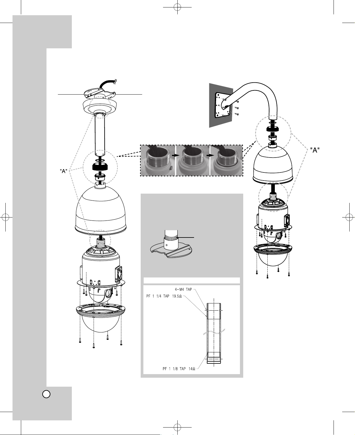
Pendant mount (LPT-EP551OS/LPT-EP553OS) Wall mount (LPT-EP551OS/LPT-EP553OS)
■ How to install
“A” Pipe threads should be clean and
rust free. Use a sealer (such as
Teflon™ tape or silicone sealer) on
the threads.
Note: The pipes and brackets for
mounting are not supplied.
Reference: Specifications of LG Standard pipe.
Add thread
sealing tape
abc
LPT-EP553OS_ATURALI_ENG.qxp:LPT-EP553PS_ATURALI_ENG 2008.4.29 5:38 PM Page 8
9
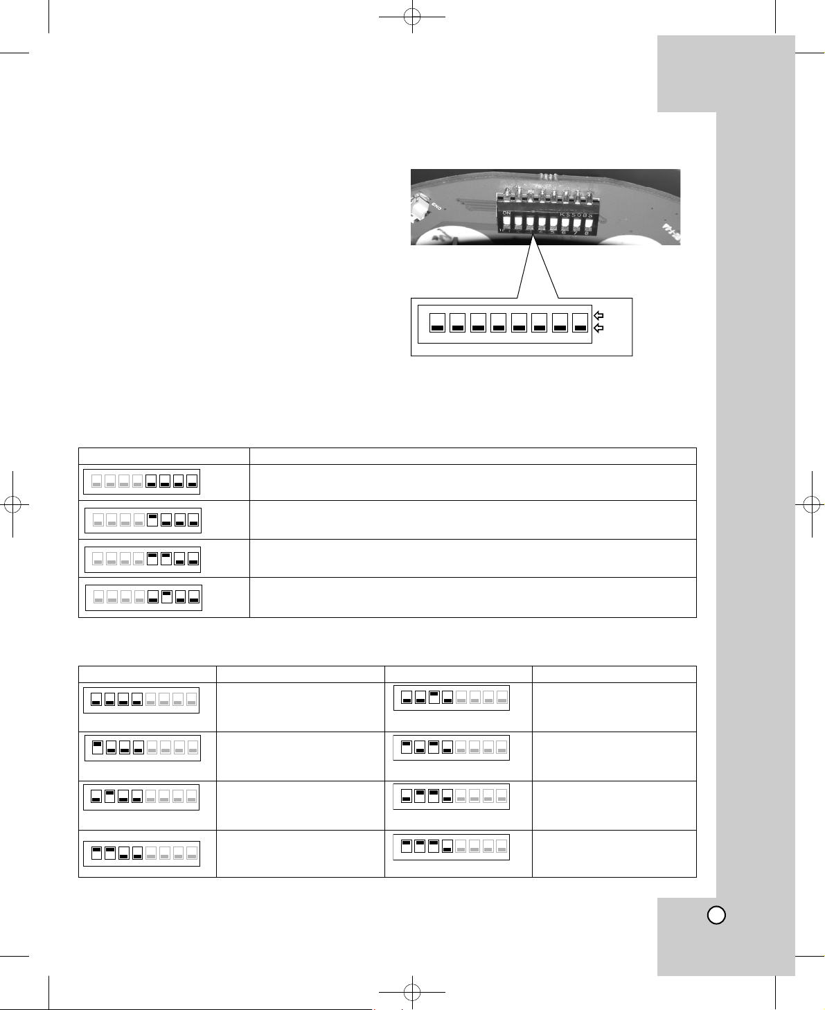
Setting the Switch
The DIP switch of the camera is one 8-bit switches
and employs RS-485 communication mode as basic
use. Switch settings are read into the camera when
the power is turned on. Make sure to turn it off, then
turn it back after changing the switch settings.
RS-485 Parameter Setup
The selected protocol,communication parameters,
and set unit numbers are read into the camera when
power is switched on.
1. Turn off the camera.
2. Remove the dome cover from the camera.
3. Separate the dome camera body from camera
mounting bracket.
4. Set the DIP switch on the bottom part of the cam-
era according to the function shown in the table of
the below.
5. Turn on the camera. Setup is completed.
ON
1 2 3 4 5 6 7 8
ON
OFF
SW2 on main board
Switch position (5~8) Function Effect
When the camera is connected to the controller with LG Multix protocol.
The controller with LG Multix protocol allow all control for this camera.
When the camera is connected to the controller with LG protocol.
The controller with LG protocol allow only limited control for this camera.
When the camera is connected to the controller with Pelco P protocol.
The controller with Pelco P protocol allow only limited control for this camera.
When the camera is connected to the controller with Pelco D protocol.
The controller with Pelco D protocol allow only limited control for this camera.
ON
1 2 3 4 5 6 7 8
ON
1 2 3 4 5 6 7 8
ON
1 2 3 4 5 6 7 8
ON
1 2 3 4 5 6 7 8
Switch position (1~4) Function Effect Switch position (1~4) Function Effect
5678
ON
1234
5678
ON
1234
5678
ON
1234
5678
ON
1234
5678
ON
1234
5678
ON
1234
5678
ON
1234
ON
1 2 3 4 5678
Note: If you are not using the controller with LG protocol, there may be some limitation of function control.
Baud Rate 9,600 BPS
communication speed
Baud Rate 1,200 BPS
communication speed
Baud Rate 2,400 BPS
communication speed
Baud Rate 4,800 BPS
communication speed
Baud Rate 19,200 BPS
communication speed
Baud Rate 38,400 BPS
communication speed
Baud Rate 57,600 BPS
communication speed
Baud Rate 115,200 BPS
communication speed
LPT-EP553OS_ATURALI_ENG.qxp:LPT-EP553PS_ATURALI_ENG 2008.4.29 5:38 PM Page 9
10
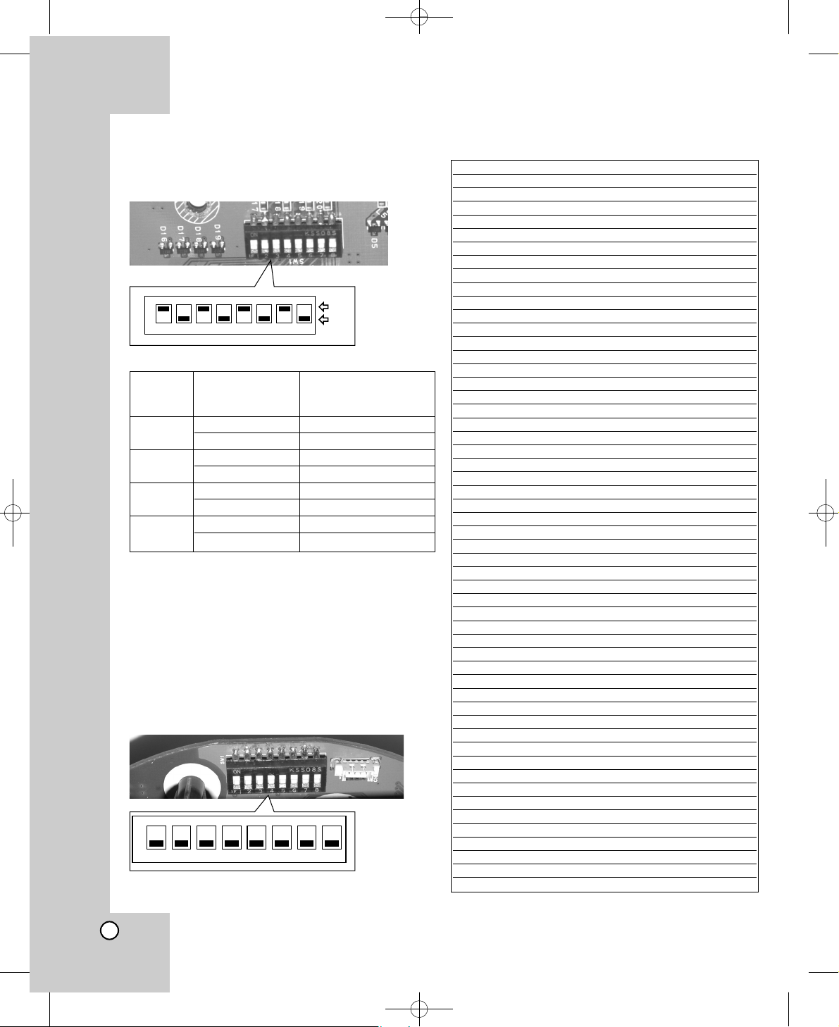
Alarm Output Mode Setting
You can set the Alarm Output to the normal open or
normal close mode.
Camera ID Setting
This camera has the camera ID set to “0” at the time
of the shipment. If you use 2 cameras or more
simultaneously, change the ID to “2” using the 8-bit
DIP switch of the 2 camera with a screwdriver.
Set the camera ID setting referring to the pictures
and the table on the below.
• The default setting of the camera ID is 0.
The table for the camera ID setting
ON
1 2 3 4 5 6 7 8
ON
1 2 3 4 5 6 7 8
ON
OFF
Alarm Switch Number Function Effect
Output (Position)
Number
1 1 (ON), 2 (OFF) Normal Open mode
1 (OFF), 2 (ON) Normal Close mode
2 3 (ON), 4 (OFF) Normal Open mode
3 (OFF), 4 (ON) Normal Close mode
3 5 (ON), 6 (OFF) Normal Open mode
5 (OFF), 6 (ON) Normal Close mode
4 7 (ON), 8 (OFF) Normal Open mode
7 (OFF), 8 (ON) Normal Close mode
SW1 on IF board
SW1 on main board
ID SW1 SW2 SW3 SW4 SW5 SW6 SW7 SW8
0 OFF OFF OFF OFF OFF OFF OFF OFF
1 ON OFF OFF OFF OFF OFF OFF OFF
2 OFF ON OFF OFF OFF OFF OFF OFF
3 ON ON OFF OFF OFF OFF OFF OFF
4 OFF OFF ON OFF OFF OFF OFF OFF
5 ON OFF ON OFF OFF OFF OFF OFF
6 OFF ON ON OFF OFF OFF OFF OFF
7 ON ON ON OFF OFF OFF OFF OFF
8 OFF OFF OFF ON OFF OFF OFF OFF
9 ON OFF OFF ON OFF OFF OFF OFF
10 OFF ON OFF ON OFF OFF OFF OFF
11 ON ON OFF ON OFF OFF OFF OFF
12 OFF OFF ON ON OFF OFF OFF OFF
13 ON OFF ON ON OFF OFF OFF OFF
14 OFF ON ON ON OFF OFF OFF OFF
15 ON ON ON ON OFF OFF OFF OFF
16 OFF OFF OFF OFF ON OFF OFF OFF
17 ON OFF OFF OFF ON OFF OFF OFF
18 OFF ON OFF OFF ON OFF OFF OFF
19 ON ON OFF OFF ON OFF OFF OFF
20 OFF OFF ON OFF ON OFF OFF OFF
21 ON OFF ON OFF ON OFF OFF OFF
22 OFF ON ON OFF ON OFF OFF OFF
23 ON ON ON OFF ON OFF OFF OFF
24 OFF OFF OFF ON ON OFF OFF OFF
25 ON OFF OFF ON ON OFF OFF OFF
26 OFF ON OFF ON ON OFF OFF OFF
27 ON ON OFF ON ON OFF OFF OFF
28 OFF OFF ON ON ON OFF OFF OFF
29 ON OFF ON ON ON OFF OFF OFF
30 OFF ON ON ON ON OFF OFF OFF
31 ON ON ON ON ON OFF OFF OFF
32 OFF OFF OFF OFF OFF ON OFF OFF
33 ON OFF OFF OFF OFF ON OFF OFF
34 OFF ON OFF OFF OFF ON OFF OFF
35 ON ON OFF OFF OFF ON OFF OFF
36 OFF OFF ON OFF OFF ON OFF OFF
37 ON OFF ON OFF OFF ON OFF OFF
38 OFF ON ON OFF OFF ON OFF OFF
39 ON ON ON OFF OFF ON OFF OFF
40 OFF OFF OFF ON OFF ON OFF OFF
41 ON OFF OFF ON OFF ON OFF OFF
42 OFF ON OFF ON OFF ON OFF OFF
43 ON ON OFF ON OFF ON OFF OFF
44 OFF OFF ON ON OFF ON OFF OFF
45 ON OFF ON ON OFF ON OFF OFF
46 OFF ON ON ON OFF ON OFF OFF
47 ON ON ON ON OFF ON OFF OFF
48 OFF OFF OFF OFF ON ON OFF OFF
49 ON OFF OFF OFF ON ON OFF OFF
50 OFF ON OFF OFF ON ON OFF OFF
51 ON ON OFF OFF ON ON OFF OFF
52 OFF OFF ON OFF ON ON OFF OFF
LPT-EP553OS_ATURALI_ENG.qxp:LPT-EP553PS_ATURALI_ENG 2008.4.29 5:38 PM Page 10
 Loading...