


Network Camera
Owner’s Manual
MODEL: LPT-DW113P
Before installing and using the camera, please read this owner's
manual carefully and retain for future reference.
2
This lightning flash with arrowhead
symbol within an equilateral triangle is
intended to alert the user to the presence
of uninsulated dangerous voltage within
the product’s enclosure that may be of
sufficient magnitude to constitute a risk of
electric shock to persons.
The exclamation point within an equilateral triangle is intended to alert the user to
the presence of important operating and
maintenance (servicing) instructions in the
literature accompanying the product.
WARNING: Do not install this equipment in a confined space such as a bookcase or similar unit.
WARNING: This is a class A product. In a domestic
environment this product may cause radio interference in which case the user may be required to take
adequate measures.
WARNING: Wiring methods shall be in accordance
with the National Electric Code, ANSI/NFPA 70.
WARNING: To reduce a risk of fire or electric shock,
do not expose this product to rain or moisture.
CAUTION: The apparatus should not be exposed
to water (dripping or splashing) and no objects filled
with liquids, such as vases, should be placed on the
apparatus.
CAUTION: This installation should be made by a
qualified service person and should conform to all
local codes.
CAUTION: To avoid electrical shock, do not open the
cabinet. Refer servicing to qualified personnel only.
FCC WARNING: This equipment may generate or
use radio frequency energy. Changes or modifications to this equipment may cause harmful interference unless the modifications are expressly
approved in the instruction manual. The user could
lose the authority to operate this equipment if an
unauthorized change or modification is made.
REGULATORY INFORMATION: FCC Part 15
This equipment has been tested and found to comply
with the limits for a Class A digital device, pursuant to Part 15 of the FCC Rules. These limits are
designed to provide reasonable protection against
harmful interference when the equipment is operated in a commercial environment. This equipment
generates,uses,and can radiate radio frequency
energy and,if not installed and used in accordance
with the instruction manual,may cause harmful interference to radio communications. Operation of this
equipment in a residential area is likely to cause
harmful interference in which case the user will
be required to correct the interference at his own
expense.
• A suitable conduit entries, knock-outs or glands
shall be provided in the cable entries of this
product in the end user.
• Caution: Danger of explosion if battery is incorrectly replaced. Replaced only with the same or
equivalent type recommended by the manufacturer. Dispose of used batteries according to the
manufacturer’s instructions.
• Holes in metal, through which insulated wires
pass, shall have smooth well rounded surfaces
or shall be provided with brushings.
CAUTION: TO REDUCE THE RISK
OF ELECTRIC SHOCK
DO NOT REMOVE COVER (OR BACK)
NO USER-SERVICEABLE PARTS INSIDE
REFER SERVICING TO QUALIFIED SERVICE
PERSONNEL.
CAUTION
RISK OF ELECTRIC SHOCK
DO NOT OPEN
The subject camera have not been evaluated for
wall or ceiling mounting.
Introduction
ConnectionsInstallationSetup
configuration
OperatingClient
Program
Additional
Information
Specifications
3
Disposal of your old appliance
1. When this crossed-out wheeled bin symbol
is attached to a product it means the product is covered by the European Directive
2002/96/EC.
2. All electrical and electronic products
should be disposed of separately from the
municipal waste stream via designated
collection facilities appointed by the government or the local authorities.
3. The correct disposal of your old appliance
will help prevent potential negative consequences for the environment and human
health.
4. For more detailed information about dis
posal of your old appliance, please contact
your city office, waste disposal service or
the shop where you purchased the product.
This product is manufactured to comply with
EMC Directive 2004/108/EC and Low Voltage
Directive 2006/95/EC.
European representative :
LG Electronics Service Europe B.V.
Veluwezoom 15, 1327 AE Almere,
The Netherlands (Tel : +31-036-547-8940)
IMPORTANT SAFETY
INSTRUCTIONS
1. Read these instructions.
2. Keep these instructions.
3. Heed all warnings.
4. Follow all instructions.
5. Do not use this apparatus near water.
6. Clean only with dry cloth.
7. Do not block any ventilation openings. Install in
accordance with the manufacturer’s instructions.
8. Do not install near any heat sources such as radiators, heat registers, stoves, or other apparatus
(including amplifiers) that produce heat.
9. Do not defeat the safety purpose of the polarized
or grounding-type plug. A polarized plug has two
blades with one wider than the other. A grounding
type plug has two blades and a third grounding
prong. The wide blade or the third prong are provided for your safety. If the provided plug does not fit
into your outlet, consult an electrician for replacement of the obsolete outlet.
10. Protect the power cord from being walked on or
pinched particularly at plugs, convenience receptacles, and the point where they exit from the apparatus.
11. Only use attachments/accessories specified by the
manufacturer.
12. Use only the cart, stand, tripod, bracket, or table
specified by the manufacturer, or sold with apparatus. When a cart is used, use caution when moving
the cart/ apparatus combination to avoid injury from
tip-over.
13. Unplug this apparatus during lightning storms or
when unused for long periods of time.
14. Refer all servicing to qualified service personnel.
Servicing is required when the apparatus has been
damaged in any way, such as power- supply cord or
plug is damaged, liquid has been spilled or objects
have fallen into the apparatus, the apparatus has
been exposed to rain or moisture, does not operate
normally, or has been dropped.

4
Contents
Introduction .........................................5
Features ................................................................. 5
Safety Precautions ................................................. 6
Identification of Camera ......................................... 7
Identification of the Ceiling Mount Assembly ......... 8
Connections ........................................9
Before Connection ................................................. 9
PC Requirements ................................................... 9
Connection Overview ............................................. 9
Connecting Alarm Output ..................................... 10
Connecting Alarm Input........................................ 10
Connecting Audio Input/Output ............................ 10
Connecting to the Network ...................................11
Connecting the Monitor .........................................11
Connecting Power Source ....................................11
Connecting the Camera to a Computer using the
Cross Cable ......................................................... 12
Connecting the Camera to the Network using the
LAN cable without the Broadband Router ........... 14
Connecting the Camera to the Network using the
LAN Cable with the Broadband Router ............... 15
Installation .........................................17
Precautions .......................................................... 17
Mounting the Camera on the Ceiling ................... 17
Setup configuration .........................19
About Home Page................................................ 19
Logging in to the Setup Page .............................. 19
General Setup ...................................................... 20
Network Setup ..................................................... 21
Video & Audio Setup ............................................ 22
Color Setup .......................................................... 23
Alarm Setup ......................................................... 23
DIO Setup ............................................................ 24
Preset Setup ........................................................ 25
Camera Setup ...................................................... 26
Homepage Update ............................................... 28
Firmware Update ................................................. 28
Operating ...........................................29
Logging in to the Web Viewer .............................. 29
Using the Web Viewer ......................................... 29
Client Program .................................. 32
Client Program Installation ................................... 32
Using the DW113 Viewer ..................................... 32
Register the Site Name and Connect the
Camera using the DW113 Viewer ........................ 34
Setup the DW113 Viewer ..................................... 35
PTZ and Preset move control using the
Keyboard .............................................................. 36
Using the IP Finder .............................................. 36
Finding the IP Address of the Camera(s) ........... 36
Assigning the IP Address to the Camera ............ 37
Using the "CSMtoAVI" Program ........................... 37
Additional Information ..................... 38
Mounting the Camera using the optional Bell
Bracket ................................................................ 38
How to register the No-IP Web site for DDNS
function ................................................................ 41
Specifications ................................... 42

Introduction
ConnectionsInstallationSetup
configuration
OperatingClient
Program
Additional
Information
Specifications
5
Introduction
Features
x Embedded Web Server
This camera is equipped with a web server function. The camera can be accessed using the web
browser on the computer to view the surveillance
images. Up to 50 users can simultaneously access
a single camera on the network.
x Event Recording Function
When an event (motion detection, alarm input)
occurs, this camera records the live images and
sends the recorded images to the FTP server.
x E-mail Sending Function
If an alarm or motion detection occurs the live
image is captured and sent via e-mail using an
external e-mail server.
x Audio Function
The sound of the camera can be heard via speaker or sound can be input to the camera using the
microphone.
x User Home page
It is possible to change the home page of the
camera.
x Easy Firmware Upgrade
x Relay Function
The relay can be controlled using the web viewer.
x High Sensitivity Support
The camera provides a high quality picture with
1/4" EX-view CCD.
x Preset Setting
Preset setting is the function to register camera
monitoring positions (preset positions) associated
with position numbers. By entering the position
numbers the cameras can be moved to the preset
positions.
A maximum of 128 preset positions are available.
The holding time is adjustable.
x Preset Tour
Tours all preset positions that have already been
registered.
x Auto Flip
The auto flip function allows the tilt angle to widen
up to 180°. The image on the monitor screen is
flipped horizontally and vertically at the tilt angle of
approx. 90°.
x Sophisticated Design
This is a surveillance camera that can fit any
indoor surroundings because it comes in a compact size and has a sophisticated design.
x Zoom Lens & Auto Focus
This camera can zoom maximum of 54 times with
optical and digital zoom (Optical zoom: 27 times,
Digital zoom: 2 times). If the WDR (Wide Dynamic
Range) function is activated the digital zoom function is not available.
x Alarm-In Function
Alarm input signals are supplied from external
devices through the ALARM IN connector to turn
the camera to a preset position.
x Day & Night Function
This camera can select either color or black &
white. It is possible to set color in the daytime and
black & white at night to suit the low illumination
(filter conversion type).
x DSS (Digital Slow Shutter) Function
It is possible to carry out highly sensitive surveillance with the DSS (Digital Slow Shutter) function.
x WDR (Wide Dynamic Range) Function
The camera can be set to the best condition for
watching it inside or outside with a strong back
light.
x Power Supply
This camera must only be operated using a DC
12V certified/listed class 2 power supply.
Notes:
• The noise may occur from the camera during the
camera is working.
• The pictures used in this owner's manual are
based on Windows XP.
Introduction

6
Safety Precautions
x Do not attempt to disassemble the camera
To prevent electric shock, do not remove screws
or covers. There are no user serviceable parts
inside. Ask a qualified service personnel for servicing.
x Avoid the camera with direct sunlight
Do not aim the camera at bright objects. Whether
the camera is in use or not, never face it with
direct sunlight or other extremely bright objects.
Otherwise blooming or smear may be caused.
x Handle the camera with care
Do not abuse the camera. Avoid striking, shaking,
etc. The camera could be damaged by improper
handling or storage.
x Do not use strong solvents or detergents
Use a dry cloth to the camera when it is dirty. If
it is hard to remove the dirt on the camera, use a
mild detergent and wipe it gently.
x Do not install this camera upside down
This camera is designed for mounting on the ceiling or wall. If you install this camera upside down,
for example, mounted on the floor, it may cause
malfunction.
x Do not use the camera in such places as
shown below.
The lens may become cloudy due to condensation
if the camera is used under the following conditions.
- Rapid temperature fluctuation by switching an
air conditioner on and off.
- Rapid temperature fluctuation due to frequent
door opening and closing.
- Use in an environment where eyeglasses
become foggy.
- Use in a room filled with cigarette smoke or
dust.
If the lens becomes cloudy due to condensation,
remove the dome cover and wipe all moist
surfaces with a soft cloth.
x Before operating, please check proper tem-
perature, humidity and power source ratings.
Use the camera under conditions where temperature is between -10 °C – +50 °C and humidity is
below 80%.
The input power source is DC 12V (24W).
x Consumables
Parts having contacts such as the lens-drive
motors, cooling fan built inside the camera are
subject to wear with time. About replacement and
maintenance of such parts, please ask the nearest
service center.
Accessories
Software CD
Screws and
Wrench
Terminal Blocks
Cross Cable

Introduction
ConnectionsInstallationSetup
configuration
OperatingClient
Program
Additional
Information
Specifications
7
a ALARM OUT Terminal (CH1/CH2)
Output terminals for alarm signal.
b VIDEO OUT (Video output cable with BNC
connector)
Connects the video connector to the monitor.
cLAN Port
For network connection with a LAN cable.
dALARM IN (Sensor Input) Terminal (CH1/CH2)
Input terminals for alarm signal.
eLocking bracket
Attach the Ceiling Mount Assembly with camera
body using the locking bracket.
fLocking screw
Tighten this screw to fixing the Ceiling Mount
Assembly with camera body.
gDC 12V Terminal (Class 2 Only)
DC 12 V power input terminal.
h RS-232 Console
Not used (For service only).
i AUDIO Terminal (MIC Input / SPEAKER
Output)
Input/Output terminals for audio signal.
jCamera body
Identification of Camera
a
b
c
h
i
j
d
f
e
g
Introduction
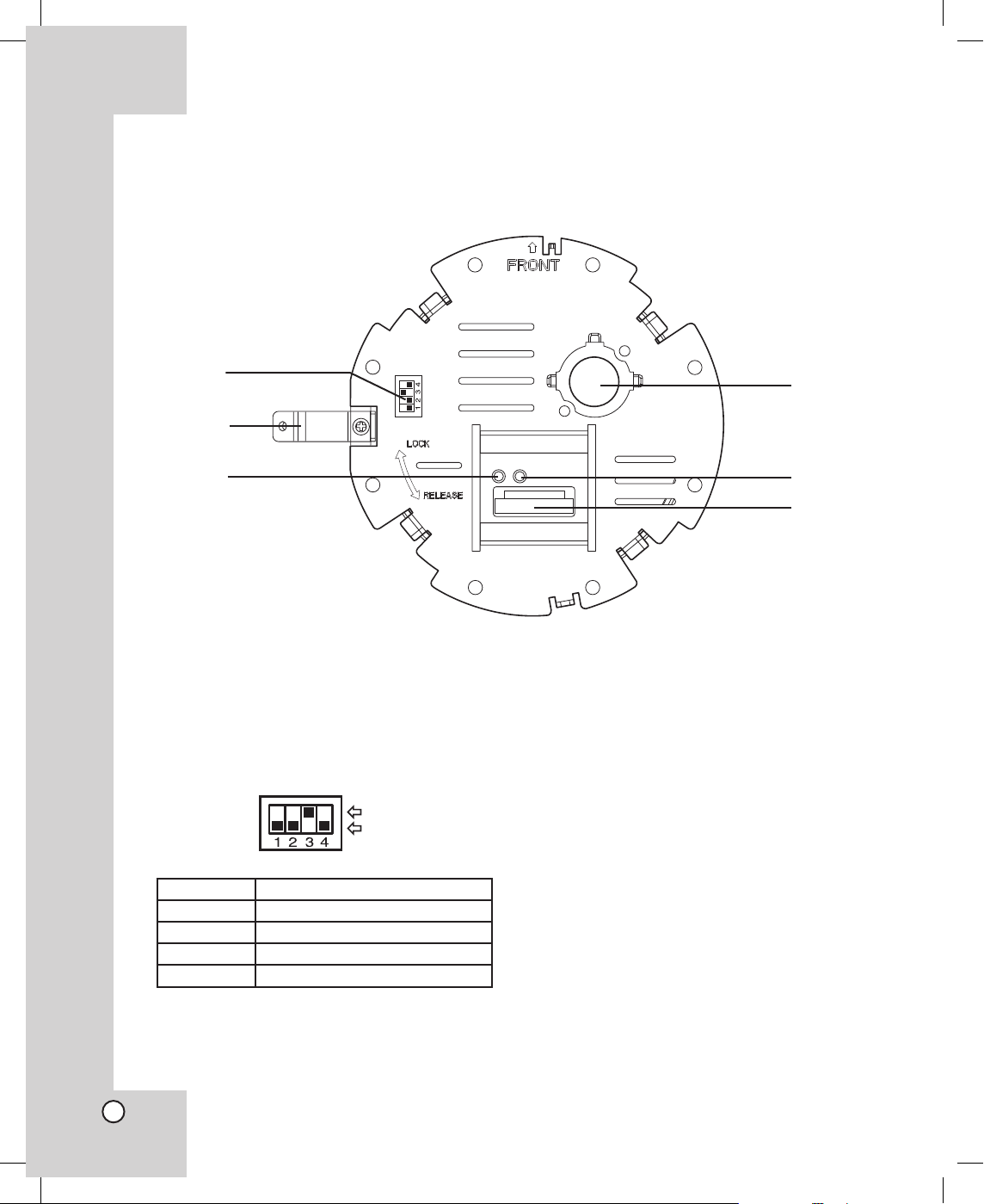
8
a Dip Switch
You can reset the factory default settings.
The factory default position of the dip switch and
function are as shown below.
Switch No. Description
1 Factory Reset.
2 Not used.
3 Not used (Terminal mode ON).
4 Not used (Only terminal mode).
b Locking bracket of Ceiling Mount Assembly
Attach the Ceiling Mount Assembly with camera
body using the locking bracket.
cLAN Indicator LED
Lights when the LAN cable is connected and
activated correctly.
dCooling fan
e ACT Indicator LED
Blinking when the camera is activated.
f Communication terminal between camera
body and the Ceiling Mount Assembly
Connect the communication cable of the camera
body.
c
e
d
f
a
b
Identification of the Ceiling Mount Assembly
ON
OFF
Introduction
ConnectionsInstallationSetup
configuration
OperatingClient
Program
Additional
Information
Specifications
9
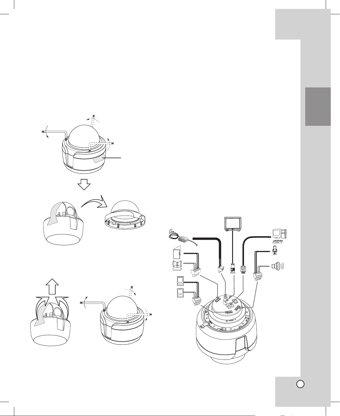
Before Connection
Removing the protection tape
Before using the camera, remove the protection tape.
Caution: Remove the protection tape carefully.
1. Loose the screws using the wrench and remove
the dome cover as shown below.
2. Remove the protection tape and attach the dome
cover.
PC Requirements
x OS (Operating System): Windows 98, Windows
2000 or Windows XP, DirectX 8.1 or higher.
x CPU: Intel Pentium III with 1GHz or higher.
x RAM: 256 MB or higher.
x Graphics Card: AGP VGA with 64 MB Video RAM
or higher.
(Minimum Resolution: 1024 x 768)
x Browser : Internet Explorer 6.0 or higher.
Connection Overview
Precautions
• The connections should be made by qualified service personnel or system installers in accordance
with all local codes.
• DC 12 V (24W) should be used.
When powered up, the camera performs a selfcheck (including one panning, tilting, zooming and
focusing operation).
Connections
Protection
tape.
Connections

10
Connecting Alarm Output
Connect the alarm (relay) using the terminal block.
Terminal No. Description
1, 2 Alarm Out CH1
3, 4 Alarm Out CH2
Note:
Relay Output Specification (Default: Open)
- Maximum Load Power: 100mA@DC 20V,
100mA @ AC 28V.
- Use a relay if the voltage or current of the con
-
nected device exceeds the ratings.
Connecting Alarm Input
Connect up to 2 alarm sensors using the terminal
block.
Terminal No. Description
1, 2 Alarm Input CH1
3, 4 Alarm Input CH2
Note:
Alarm sensor input Specification (Default: Open)
- Switch open or close by an external sensor.
- You can switch by using the program.
Connecting Audio Input/Output
Connect the audio signal using the terminal block.
Terminal No. Description
1, 2 Speaker
3, 4 Mic.
Notes:
• Recommended Audio device
- Mic.: Use the Carbon Microphone.
- Speaker: Use the speaker with an amplifier.
• You should install the microphone from the camera
with 1 meter length or more. If not, the noise may
occur from the microphone by the camera.
5~7 mm
To Alarm Out
CH1
To Alarm Out
CH2
5~7 mm
To Alarm Input
CH1
To Alarm Input
CH2
5~7 mm
SPEAKER
MIC
Introduction
ConnectionsInstallationSetup
configuration
OperatingClient
Program
Additional
Information
Specifications
11
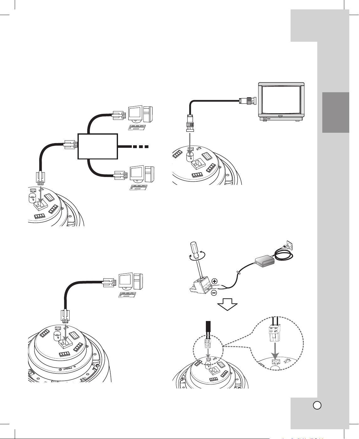
Connecting to the Network
Connect the LAN port with a straight or cross ethernet cable.
• For broadband router connection
Use a straight cable.
• For PC connection
Use a cross cable.
Connecting the Monitor
The video signal connection between the camera and
the monitor.
Connecting Power Source
Connect a DC 12 V (24W) power source to the DC
12 V input terminal with 3 and # aligned correctly as
shown below.
Cross Cable
Computer
Straight Cable
Network
Broadband
Router
Connections

12
Connecting the Camera to a
Computer using the Cross
Cable
When you turn the camera on for the first time, it will
need camera setting for the network.
1. Connect the camera to a computer using the
cross cable.
2. Connect the power source to the input terminal
on the camera.
3. Insert the plug of power cord into a wall outlet.
The camera will be turns on.
4. Turn on the computer and set the network con
-
figuration of the computer as shown below.
1) Open the [Local Area Connection Properties]
windows.
2) Select the [Internet Protocol [TCP/IP]] and
click [Properties].
3) Select [Use the following IP address] option.
4) Click [Advanced] icon.
The [Advanced TCP/IP Settings] window is
displayed.
5) Click [Add...] icon of the [IP addresses] option.
The [TCP/IP Address] window is displayed.
6) Enter the IP address and Subnet mask.
For example:
- IP address: 192 . 168 . 1 . n
(n: You can use the number from 0 to 255
except 0, 1 and 8. The number should be
different from the camera.)
- Subnet mask: 255 . 255 . 255 . 0

Introduction
ConnectionsInstallationSetup
configuration
OperatingClient
Program
Additional
Information
Specifications
13
7) Click [Add].
The new IP address is displayed in the IP
addresses option.
8) Click [OK] or [Close] repeatedly to save the
settings.
5. Start the web browser on the computer.
6. Enter the IP address (192.168.1.8) of the camera
into the Address bar and press Enter.
The home page of the camera is displayed.
Note:
If the Home page does not displayed, check the
IP settings of the computer or reset the camera.
7. For more detail using the home page of the cam
-
era, refer to [Setup configuration] and [Operating].
How to reset the camera
1. Detach the Ceiling Mount Assembly from
the camera body and find Dip switch as
shown right.
2. Set the first dip switch to ON and wait 5 sec
-
onds in power on mode.
3. Set to OFF the switch after 5 seconds.
Wait 2 minutes or more after reset.
The network settings will be changed to
default values.
4. Attach the Ceiling Mount Assembly to the
camera body.
Note:
The factory default settings are as shown below.
• Server Title: LPT-DW113.
• Port numbers
- Web server port: 80
- Login port : 9000
- Stream port: 9001
- Audio port: 9002
- Interactive audio port: 9003
• IP Setup
- IP address: 192.168.1.8
- Subnet mask : 255.255.255.0
Gateway: 192.168.1.1
• DNS Server
- First DNS server: 164.124.101.2
- Second DNS server: 210.104.1.3
• Login ID and Password of Administrator
- ID: admin
- Password: admin
ON
OFF
ON
OFF
ON
OFF
Connections

14
Connecting the Camera to the
Network using the LAN cable
without the Broadband Router
Assigning the Static IP Address to
the Camera
1. Follow steps 1-6 as shown [Connecting the
Camera to a Computer using the Cross Cable] on
page 11.
2. Click the [Setup] icon on the home page.
The login page appears.
3. Enter the user ID and password of administrator,
then click Login.
The user ID [admin] and the password [admin]
are set at the factory for the administrator. You
can change them in the [General Setup] menu
(see page 20)
4. Select [Network Setup] option.
5. Select [Static IP Address] and enter the IP
Address, Subnet Mask and Default Gateway of
the camera.
6. Click [Save] icon of the IP Setup option to save
the settings.
7. Click [Click Here!].
The Network Setting loading page is displayed.
After a few seconds, the changed home page
of the camera is displayed. In case of using the
cross cable, the changed home page may not
displayed but, the new IP address of the camera
is changed correctly.
8. Disconnect the cross cable from the computer
and the camera.
9. Connect the camera to the network using the LAN
cable (Straight cable).
10. Connect the computer to the network using the
LAN cable (Straight cable).
11. Set the network configuration of the computer.
12. Start the web browser on the computer and enter
the assigned IP address of the camera.
The home page of the camera is displayed.
13. For more detail using the home page of the cam
-
era, refer to [Setup configuration] and [Operating].
Notes:
• You will use the two IP address for this connection.
• Do not use the same IP address in the network.
• The static IP means the globally unique static IP.
 Loading...