

LG LP-154WX4-TLA9 Service manual
TO: TOSHIBA CORPORATION
DATE: ’08.05.07
Specification of 15.4” TFT/LCD
MODEL: LP154WX4 (TLA9)
Specification Rev. 0.2
1 / 60
ApprovedCheckedPrepared
www.jxlcd.com
www.jxlcd.com
C.J.PARK
/Eng. Dept.
/Engineer
NOTICE of RECEIPT
We accepted this specification. OME Operations, TOSHIBA Corp.
Purchasing
Dept.
PC
Hardware
Dept.
S.R.KIM
/Eng. Dept.
/Manager
S.C.YUN
/Eng. Dept.
/Senior Mgr
Y.S. Jung
/QA. Dept.
/Senior Mgr
Senr. MgrSenr. Eng.Eng.
Senr. MgrSenr. Eng.Eng.
LG Display Co., Ltd.
Date: 2008. 05. 07

Specification Rev. 0.2
- CONTENTS -
Record of Revision --------------------------------------------------------------- 3
1. Scope --------------------------------------------------------------- 4
2. General Specifications --------------------------------------------------------------- 4
2.1. Features
2.2. Dimensional Outline
3. Absolute Maximum Ratings --------------------------------------------------------------- 9
3.1. Absolute Ratings of Environment
3.2. Electrical Absolute Maximum
3.3. Mechanical ratings
3.4. The others
4. Optical Characteristics --------------------------------------------------------------- 16
4.1 Test Conditions
4.2 Optical Specifications
5. Electrical Characteristics --------------------------------------------------------------- 21
5.1. TFT LCD module
5.2. Backlight Unit
5.3. Regulation
6. Block Diagram --------------------------------------------------------------- 27
7. Input Terminal Pin Assignment --------------------------------------------------------------- 28
7.1 TFT LCD module
7.2 Backlight Unit
7.3 LVDS Transmitter
7.4 Timing Diagrams of LVDS for Transmission
7.5 Input Signal, Basic Display Colors and Gray Scale of Each Colors
8. Interface timing --------------------------------------------------------------- 33
8.1 Timing Parameters
8.2 Timing diagrams of interface signal
8.3 Power On / Off Sequence
9. Cosmetic Specification --------------------------------------------------------------- 35
9.1 Sampling
9.2 Conditions of Inspections
9.3 Defect modes
9.4 Mechanical inspection
9.5 Visual Inspection
9.6 Electrical inspection
10. Packing --------------------------------------------------------------- 39
11. Labels and Lamp Ass’y Exchange --------------------------------------------------------------- 41
12. General Precaution --------------------------------------------------------------- 53
www.jxlcd.com
www.jxlcd.com
2 / 60
Appendix --------------------------------------------------------------- 55
LG Display Co., Ltd.
Date: 2008. 05. 07
Record of Revision
Specification Rev. 0.2
3 / 60
08’.05.06
08’.05.07
0.1
Sheet(New)Rev. No.Date
Page 21
Page 37
Page 330.2
ReasonNewOldItem
All0.008’.03.12
Correct Differential
Input Threshold
Voltage
Reject range
of Maximum
distance between
defects
Min.& Max. value
of interface
Timing (DCLK)
L>16mm
L>11mm
-
-
-
Max : +100
L>15.1mm (B-to-B)
L>10.1mm (D-to-D)
Min. : 66.0 Mhz
Max. :76.0 Mhz
First
Edition
www.jxlcd.com
www.jxlcd.com
LG Display Co., Ltd.
Date: 2008. 05. 07
Specification Rev. 0.2
1. Scope
This specification is applicable to LCD manufacturer’s 15.4” diagonal size TFT-LCD module
"LP154WX4(TLA9)" designed for Personal Computer.
2. General Specification
2.1. Features
SpecificationsItem
331.2 (W) × 207.0 (H) (mm) ( 15.4 ” diagonal )Display area ( Active area)
TFT active matrixDriving Method
Number of Pixels
Pixel pitch
Pixel Arrangement
1280 (W) × 800 (H) × R,G,B (WXGA) (pixels)
0.25875 (H) × 0.25875 (V) (mm)
RGB vertical stripes
262,144 (colors)Display color
Transmissive mode, Normally whiteDisplay Mode
6 o'clock (in direction of maximum contrast)Viewing Direction
Anti – glare & hard coating 3H,HAZE(25%)Surface Treatment
LVDSInterface
Single cold-cathode fluorescent lamp for side-lightingBacklight
1)
1)
1)
4 / 60
Note 1)
344.0±0.5 (W) × 222.0±0.5 (H) / 6.5(Max) (D) (mm)Dimensional Outline
www.jxlcd.com
www.jxlcd.com
1 2 1279 1280
1
2
799
800
335.0±0.5 (W) × 210.7±0.5 (H) (mm)Bezel Opening
560g(Typ.) 575g(Max.)Weight
BGRBGRBGRBGR
BGRBGRBGRBGR
BGRBGRBGRBGR
BGRBGRBGRBGR
0.25875mm
0.25875mm
BGR
G B
R
: Pixel
: Sub-pixel
(Dots)
LG Display Co., Ltd.
Date: 2008. 05. 07
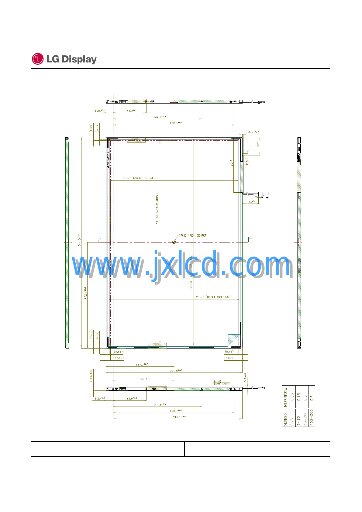
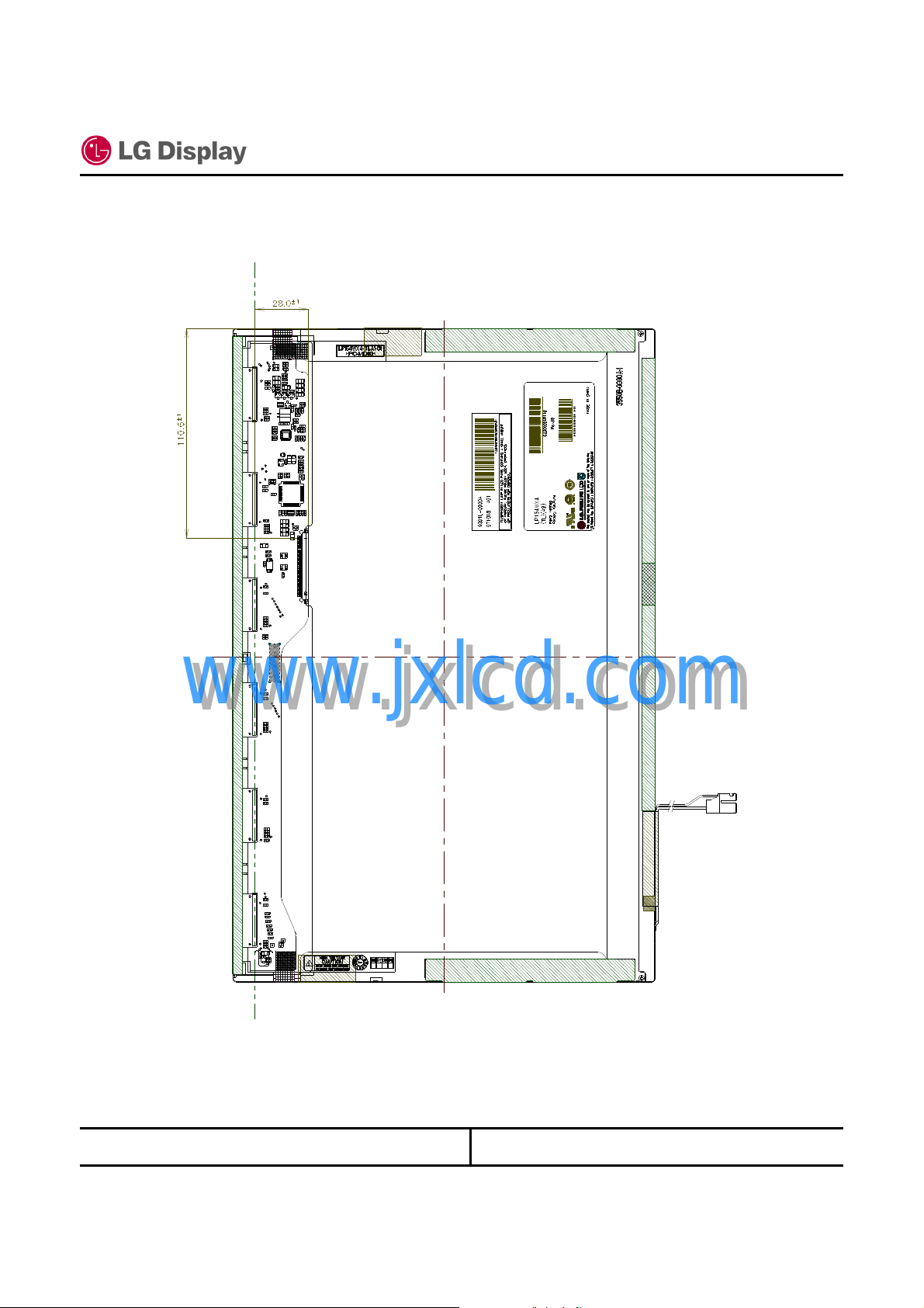
2.2. Dimensional Outline
( Front figure )
Specification Rev. 0.2
5 / 60
www.jxlcd.com
www.jxlcd.com
* The size that related with metal bezel includes tape thickness (0.05mm)
LG Display Co., Ltd.
Date: 2008. 05. 07
( Back figure )
Specification Rev. 0.2
6 / 60
www.jxlcd.com
www.jxlcd.com
LG Display Co., Ltd.
Date: 2008. 05. 07
Specification Rev. 0.2
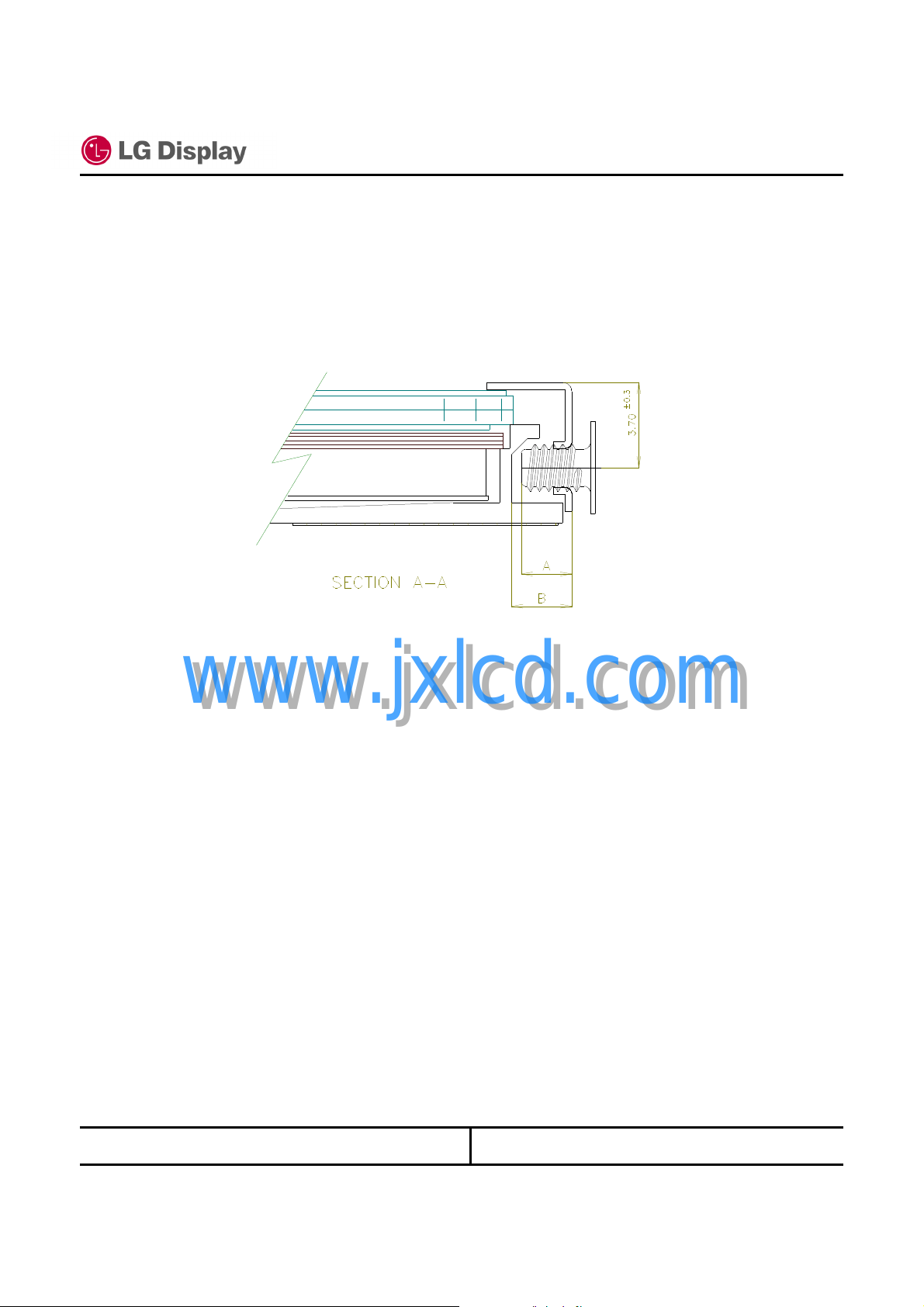
( Detail description of side mounting screw )
7 / 60
* Mounting Screw Length (A)
www.jxlcd.com
www.jxlcd.com
Notes : 1. Screw plated through the method of non-electrolytic nickel plating is preferred
to reduce possibility that results in vertical and/or horizontal line defect due to
the conductive particles from screw surface.
= 2.0(Min) / 2.5(Max)
* Mounting Screw Hole Depth (B)
= 2.5(Min)
* Mounting hole location : 3.7(typ.)
* Torque : 2.5 kgf.cm(Max)
(Measurement gauge : torque meter)
LG Display Co., Ltd.
Date: 2008. 05. 07
Specification Rev. 0.2
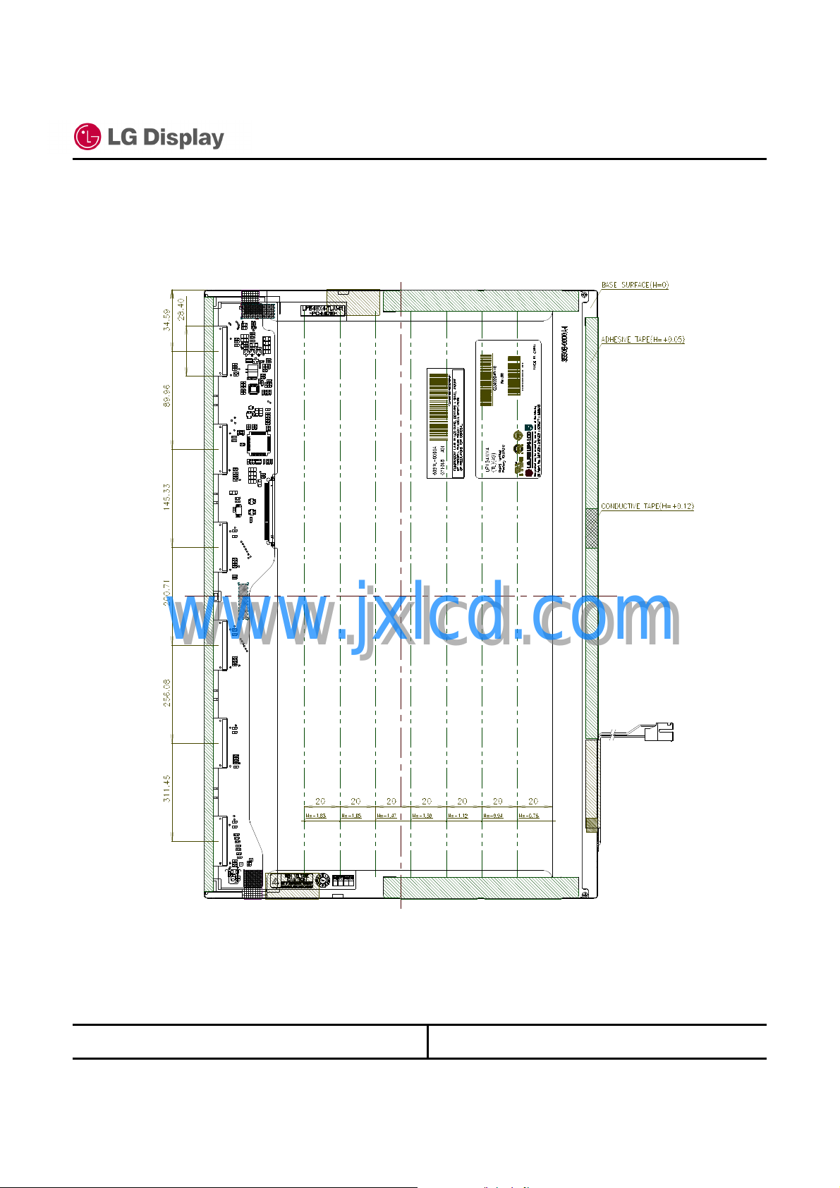
( Detail description of height of LCM back side & TAB Zone)
8 / 60
www.jxlcd.com
www.jxlcd.com
LG Display Co., Ltd.
Date: 2008. 05. 07
Specification Rev. 0.2
3. Absolute Maximum Ratings
3.1. Absolute Ratings of Environment
9 / 60
MaxMinItem NoteSymbol
Operating Ambient Temperature
Operating Temperature for Panel
Storage Temperature
Operating Ambient Humidity
Storage Humidity
Air Pressure
Air Pressure
Altitude
Altitude
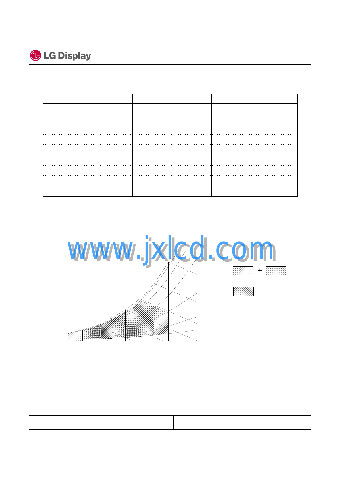
Note 1) Temperature and relative humidity range are shown in the figure below.
Wet bulb temperature should be 39°C Max, and no condensation of water.
www.jxlcd.com
www.jxlcd.com
-
-
60
-
90% 80%
60%
Unit
(1)°C+500TOP
(2)°C+500-
(1)°C+60-20TSTG
(1)%RH9010HOP
(1)%RH9010HSTG
OperationkPa101.357-
Non-operationkPa101.312-
OperationKm3-
Non-operationKm12
Wet Bulb
Temperature [℃℃℃℃]
30
20
10
0
-20
Note 2) The surface temperature caused by self heat radiation of cell itself is specified on this item.
10
20 30 40 50
Dry Bulb Temperature [℃℃℃℃]
50
40
60 70 800
LG Display Co., Ltd.
Humidity[(%)RH]
Storage
40%
Operation
20%
10%
Date: 2008. 05. 07
3.2. Electrical Absolute Maximum
(1) TFT LCD Module
Specification Rev. 0.2
10 / 60
Power Supply Voltage
Logic Input Voltage
(2) Back Light Unit
Lamp Voltage
Lamp Current
Lamp Frequency
www.jxlcd.com
www.jxlcd.com
MaxMinItem NoteSymbol
MaxMinItem NoteSymbol
Unit
at 25 ± 5°CV+4.0-0.3VDD
LVDS interfaceVVDD+0.3-0.3VIN
Unit
Broken lamp Max VoltageVRMS5000VL
mARMS6.83.0IL
kHz8045FL
LG Display Co., Ltd.
Date: 2008. 05. 07
3.3. Mechanical Ratings
Test Item NoteTest Conditions
Frequency Range 5 - 500 Hz, 14.7m/s21.5G) constant,
Mechanical Vibration
Mechanical Shock
LCD fix condition
-> See Note (2)
Pressure Resistanace
-> See Note (1)
Strength of FL Cable
www.jxlcd.com
www.jxlcd.com
Connector tension test
at side-mout part
0.5Hrs each axis (X, Y, Z direction).
Frequency Range 5 - 500 Hz, 4.9m/s2( 0.5G) constant,
0.5Hrs each axis (X, Y, Z direction).
No Destruction with the force 196 N (20 kgf, 16 mm in diameter) to
the display surface at the vertical direction.
No Destruction with the force 294.2 N (30 kgf, 30 mm in diameter)
to the back of the display surface at the vertical direction.
Only the breakage of below items will not happen after test.
( Glass.Lamp & Circuit parts)
Strength of
Rotation
force
Lead Pull
Test
Input connector : With 50 times of connector trial there must be no
damage to the shape and functionaly.
Back light connector : With 50 times of connector trial there must be
no damage to the shape and functionaly.
M2 : Max 2.5 kgfAssured torque value
Specification Rev. 0.2
70G, Pulse width 11ms, Sine Wave ±X, ±Y, ±Z direction.
* Note) Normal function is only checking points.
Cable : No disconnection of cable to the 5 trial of
360 degree rotation. See a bended state of cable.
Connector : No disconnection of cable to 10 trial of
180 degree rotation. See a bended state of cable.
Soldering portion 29.4N(3.0kgf) 10mins
*1.08mm Wire applied
Connector : 12.9N (1.32kgf) 1 sec
*1.08mm Wire applied
11 / 60
Non Operation
Operation
Non Operation* 240G, Pulse width 2 ms, Sine Wave, ±X, ±Y, ±Z direction.
Operation98 m/s2 (10G), Pulse width 11 ms, Sine Wave, ±X, ±Y, ±Z direction.
Non Operation
Fig 1-1
Fig 1-2
Fig 1-3
Non Operation
FL cable
R2
Non Operation
Non Operation
Tapping area : All bezel(Metal cover) side,
Tapping test
Definitions of failure for judgment shall be as follows:
(1) Function of the module should be maintained.
(2) Current consumption should be smaller than the specified value.
(3) Appearance and display quality should not have distinguished degradation.
(4) Luminance should be larger than the minimum value specified in optical specification.
LG Display Co., Ltd.
LCD: Full-screen gray (L32).
“Ripple (Pooling )” can not be seen in Active Area
Tapping Force: Max 3kgf.cm
Date: 2008. 05. 07
Non Operation15 times under Max. torqueRescrewed test
Operation
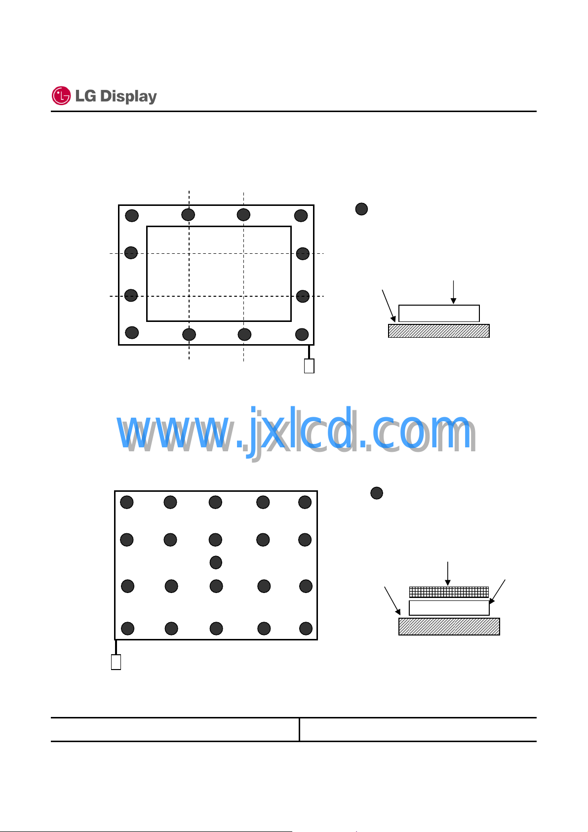
Note 1)
Specification Rev. 0.2
(1) The compression condition of front side
(a) Compression point : 12 points ( refer to Fig 1-1)
(b) Compression condition: 20kgf, 3 sec, Tool diameter: 16 mm in diameter (refer to Fig 1-3)
:COMPRESSION POINT
LCDFlat plate
12 / 60
[ Fig 1-1 ]
(2) The compression condition of rear side
www.jxlcd.com
(a) Compression point : 21 points ( refer to Fig 1-2 )
www.jxlcd.com
(b) Compression condition : 30kgf, 3 sec, Tool radius: 30 mm in diameter ( refer to Fig 1-3)
:COMPRESSION POINT
ABS natural 2.0t
Flat plate
LCD
LG Display Co., Ltd.
[ Fig 1-2 ]
Date: 2008. 05. 07
Rubber sheet
Specification Rev. 0.2
10mm in diameter
B
A
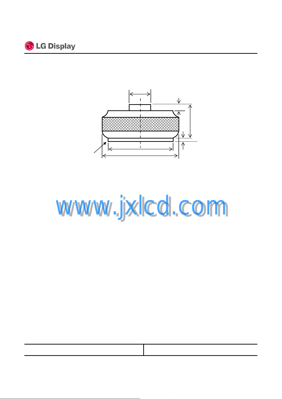
[ Fig 1-3 ]
13 / 60
10
16
1.5
(3) Dimension of the compression jig
(a) compression jig for front side A = 16 mm in diameter
B = 16 mm in diameter
(b) compression jig for rear side A = 30 mm in diameter
www.jxlcd.com
www.jxlcd.com
B = 28 mm in diameter
LG Display Co., Ltd.
Date: 2008. 05. 07
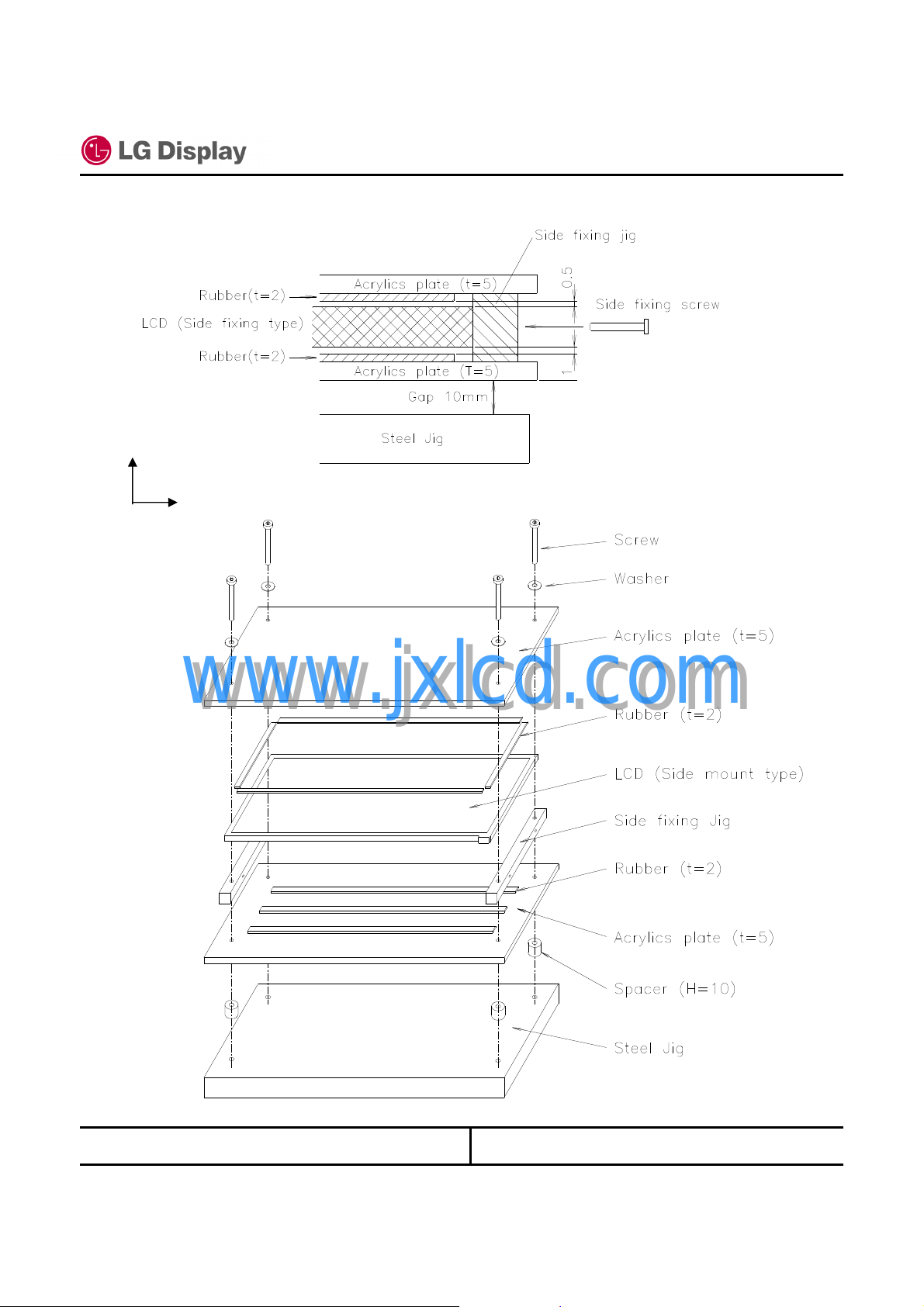
Note 2) LCD fixing condition for z direction.
Z
Y X
Specification Rev. 0.2
14 / 60
www.jxlcd.com
www.jxlcd.com
LG Display Co., Ltd.
Date: 2008. 05. 07
3.4. The Others
(1) Static electricity pressure resistance
(2) Sound noise
There should be no uncomfortable noise.
Being used under whatever surrounds, when power on/off, the panel should not generate
uncomfortable noise. And regarding specified values are negotiated if it is needed.
(3) Open / Short
No smoke, no fiery at any open/ short test
(4) MTBF : 50,000 Hr (except for backlight lamp)
Specification Rev. 0.2
15 / 60
Non OperationOperationItem Testing conditions
± 10 kV±8KV150pF, 330 ohmContact discharge
±20 KV±15KV 150pF, 330 ohmAir discharge
www.jxlcd.com
www.jxlcd.com
LG Display Co., Ltd.
Date: 2008. 05. 07
Specification Rev. 0.2
16 / 60
4. Optical Characteristics
4.1. Test Conditions
Ambient Temperature : T
Ambient Humidity : H
Supply Voltage : V
DD
Input Signal : According to typical value in "Electrical Characteristics"
FL Input Current : IL= 6.0mA
FL Driving Frequency : fLF= ( 60±5 kHz )
FL Inverter : LG Inverter (6632Z-1301A)
The measuring method is shown in 4.2. The following items are measured under stable conditions. The
optical characteristics should be measured in a dark room ( Screen illuminance < 2 lx ) or equivalent state
with the methods shown in Note (6).
25±5°C
a
65±20%RH
a
3.3V
RMS
4.2. Optical Specifications
NoteUnitMax.Typ.Min.ConditionsSymbolItem
Contrast Ratio
(Center 1 Point)
Response Time
Average luminance
(5 Point Average)
www.jxlcd.com
Cross Modulation
Luminance
Uniformity
Chromaticity
Viewing
Angle
13 Points CR Variation
www.jxlcd.com
Red
Green
Blue
White
Hor.
Ver.
Hor.
Ver.
CR
Gy
Wx
Wy
θ
θ
δW13 Points White Variation
ON
OFF
SHA
Rx
Ry
Gx
Bx
By
θ
θ
θ
Low
θ
θ
θ
Low
ms85-t
ms 1711-t
2
cd/m
L
θ=0°, φ=0°
Viewing
normal angle
L
R
CR>=10
up
L
R
CR>=5
up
R
φ = 180
φ = 0°
φ = 90°
φ = -90°
φ = 180
φ = 0°
φ = 90°
φ = -90°
θ=0°, φ=0°
Viewing
normal angle
0.564
0.319
0.295
0.513
0.127
0.109
0.283
0.299
40
40
10
30
45
45
15
35
0.594
0.349
0.325
0.543
0.157
0.139
0.313
0.329
45
45
15
35
50
50
20
40
--
--δC
--dLWhite Variation
-200170Y
0.624
0.379
0.355
0.573
0.187
0.169
0.343
0.359
-
-
-
-
-
-
-
-
-
deg.
(2), (6)--400300
(3)
*IFL=6.0mA
FL=60±5kHz
Gray Scale Level
(Color Coordinate of
the R,G,B is based
on LPL’s equipment,
and Color Coordinate
of the W is based on
LPL’s equipment)
RMS
= L63 (White)
(5)%2.0--D
(1), (6)
PR650
Only for
Color
Coordinate
(7)1.6
(7)2.0
(8)2.0
LG Display Co., Ltd.
Date: 2008. 05. 07
Specification Rev. 0.2
Attach the Lamp current – Luminance characteristics. The range of lamp current is shown in 3.2 (2)
A. Present CR Variation(13Point) Spec is based on PR-880 Equipment and can be changed by the
measuring equipment.
63
55
47
Normalized luminance
at each gray level
At normal viewing direction, during displaying the L0-L63 gray scale bar, luminance intensity inversion
can not be seen.
39
31
23
15
7
0
θ=0°, φ=0°
Viewing
normal angle
100100100
87.077.160.5
66.553.638.5
48.334.222.6
33.220.311.5
21.412.13.00
12.75.760.50
5.801.550.10
1.200.090.00
%
(1), (6)
(Center 1 Point)
17 / 60
NoteUnitMax.Typ.Min.ConditionsGray levelItem
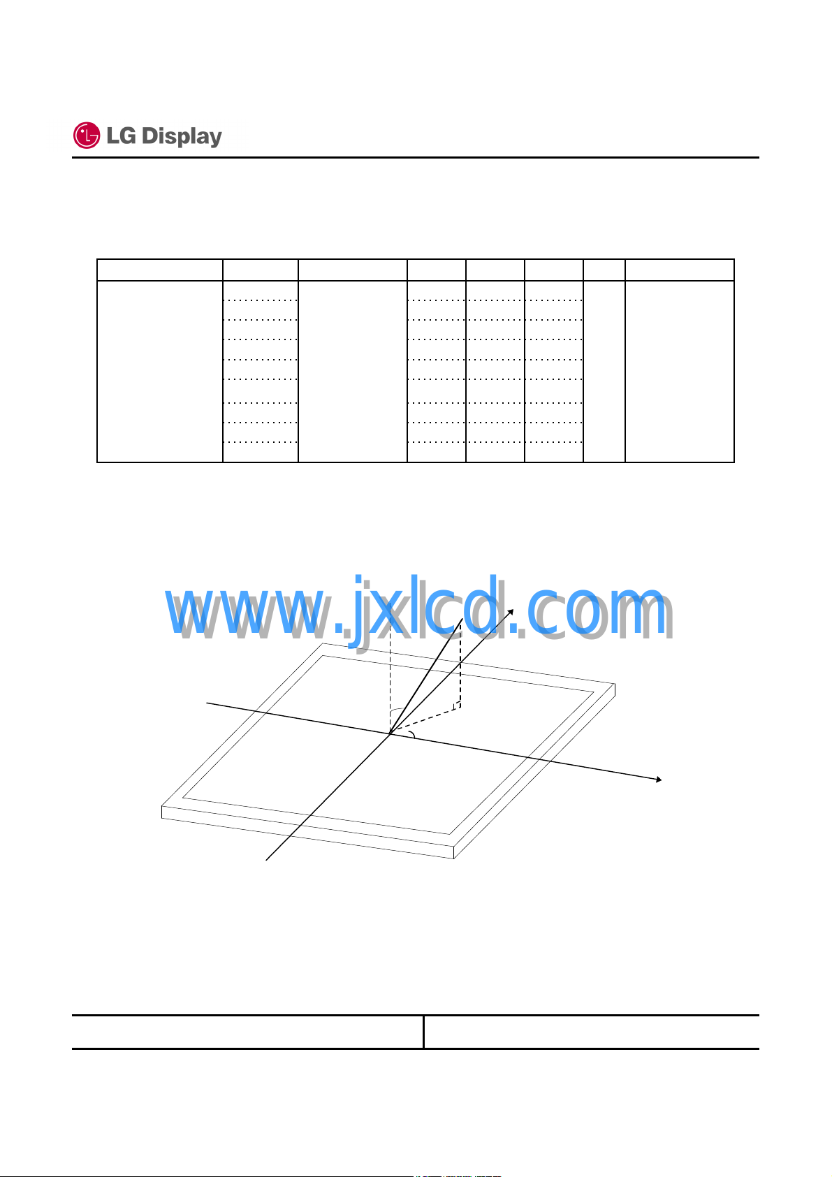
Note 1) Definition of viewing angle θ and φ
www.jxlcd.com
www.jxlcd.com
φ
= 180
Note 2) LCD fixing condition for z direction.
The contrast ratio can be calculated by the following expression.
Contrast Ratio (CR) = L63 / L0
L63 : Luminance on the white raster (gray scale level L63)
L 0 : Luminance on the black raster (gray scale level L0)
°
φ
= 270
,
Left
°
Down
,
Normal
θ
Measurement
Direction
φ
Y
φ
= 90°, Up
φ
°
= 0
,
Right
LG Display Co., Ltd.
Date: 2008. 05. 07
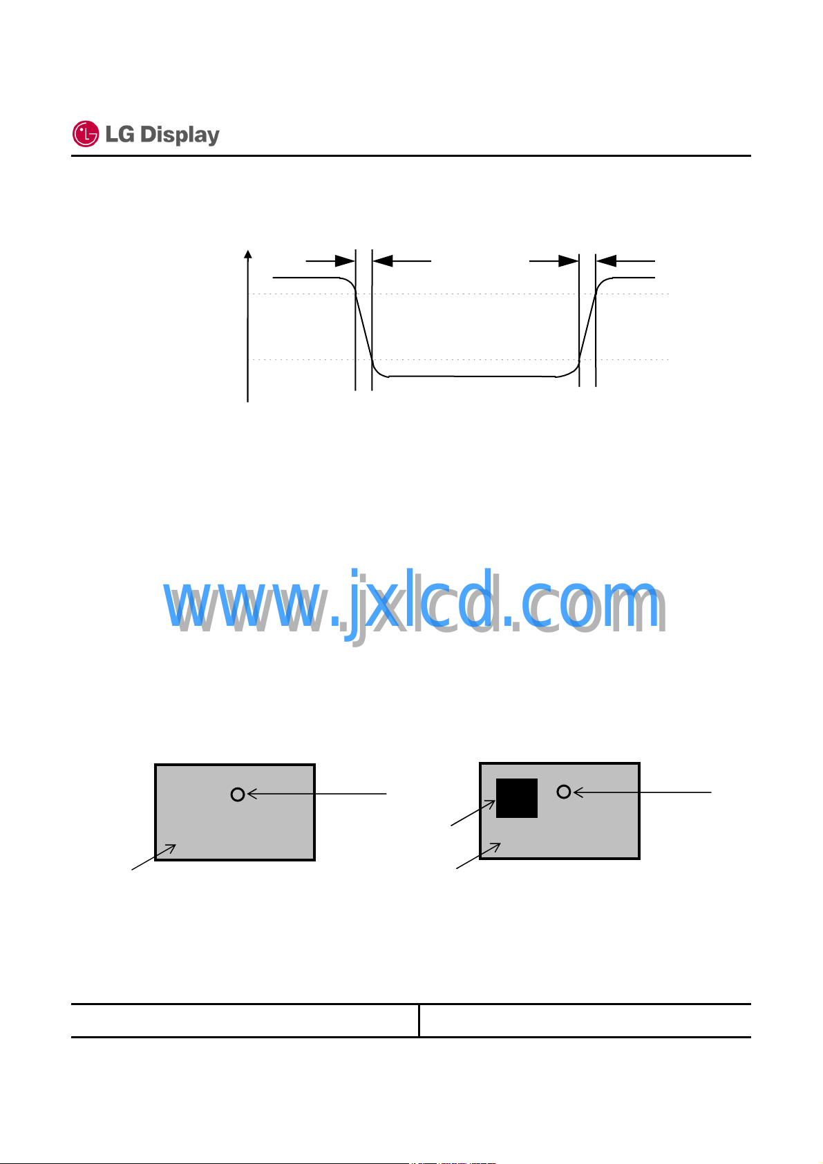
Note 3) Definition of response time
Specification Rev. 0.2
18 / 60
SHA
Ton
)
%
100
90
Optical
Response
Note 4) Definition of surface luminance of white
Measure the luminance of white at Center point. Surface luminance of white Y
Note 5) Definition of Cross Modulation (D
D
= | YB– YA| / YA×100 (%)
SHA
www.jxlcd.com
www.jxlcd.com
10
0
Bright Bright
Toff
Dark
L
Where:
YA= Luminance of measured location without darkest gray pattern (cd/m2)
YB= Luminance of measured location with darkest gray pattern (cd/m2)
(0, 0)
Gray Level 42
VIEW AREA
LG Display Co., Ltd.
YA(639, 199)
(1279, 799)
Gray Level 0
Gray Level 42
(0, 0)
VIEW AREA
(100, 100)
YA(639, 199)
(319, 399)
(1279, 799)
Date: 2008. 05. 07
 Loading...