

LG LP120CED Schematic

LG
Packaged Terminal
Air Conditioner/Heat Pump
SERVICE MANUAL
LG
CAUTION
http://www.lgservice.com
• BEFORE SERVICING THE UNIT, READ THE SAFETY
PRECAUTIONS IN THIS MANUAL.
• FOR AUTHORIZED SERVICE ONLY.

CONTENTS
1. PREFACE
1.1 SPECIFICATIONS ..........................................3
1.2 FEATURES AND BENEFITS..........................5
1.3 CONTROL LOCATIONS.................................7
1.4 ADDITIONAL CONTROLS..............................9
2.
DISASSEMBLY INSTRUCTIONS
2.1 MECHANICAL PARTS..................................11
2.1.1 FRONT GRILLE ...................................11
2.1.2 CONTROL BOX ...................................12
2.2 AIR HANDLING PARTS................................13
2.2.1 ELECTRIC HEATER
(Electric heater model only) .................12
2.2.2 CROSS FLOW FAN.............................14
2.2.3 AXIAL FAN...........................................14
2.2.4 SHROUD..............................................14
2.3 ELECTRICAL PARTS ...................................15
2.3.1 OUTDOOR MOTOR ............................15
2.3.2 INDOOR MOTOR ................................15
2.3.3 COMPRESSOR ...................................15
2.3.4 CAPACITOR ........................................15
2.3.5 POWER CORD ....................................15
2.3.6 P.C.B....................................................16
2.4.2 EVAPORATOR ....................................17
2.4.3 CAPILLARY TUBE...............................17
3.
INSTALLATION
3.1 HOW TO INSTALL THE UNIT ......................18
3.2 SUGGESTED TOOL REQUIREMENTS.......20
3.2.1 PREPARATION OF SLEEVE ..............21
3.2.2 PREPARATION OF THE FRONT
GRILLE ................................................21
3.2.3 UNIT INSTALLATION ..........................22
3.3 ELECTRICAL REQUIREMENTS ..................23
3.3.1
ELECTRICAL DATA (FOR 230V/208 MODEL)........
3.3.2 ELECTRICAL SAFETY
4.
FIELD INSTALLED ACCESSORIES
5.
FERFORMANCE DATA
6.
TROUBLESHOOTING GUIDE
6.1 OUTSIDE DIMENSIONS...............................45
6.2 PIPING SYSTEM ..........................................45
6.3 TROUBLESHOOTING GUIDE......................46
............................
.................................
...
23
23
24
40
7. SCHEMATIC DIAGRAM.....................51
8. EXPLODED VIEW..................................53
2.4 REFRIGERATION CYCLE............................16
2.4.1 CONDENSER ......................................17
9. REPLACEMENT PARTS LIST .......54
1. PREFACE
This
SERVICE MANUAL provides various service information, including the mechanical and electrical
parts, etc. This room air conditioner was manufactured and assembled under a strict quality control system.
The refrigerant is charged at the factory. Be sure to read the safety precautions prior to servicing the unit.
—2—
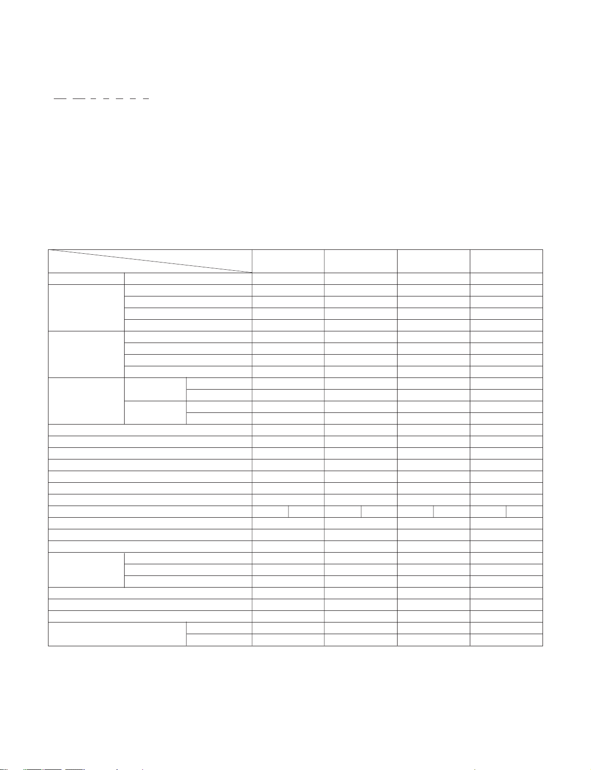
1.1 SPECIFICATIONS
LP 12 0 C E M 1
12 34 5 6 7 8 9
Digits 1,2 - LG Packaged Terminal Air Conditioner Digit 6 - Product Type
Digits 3,4 - Unit Cooling Capacity C = Air Conditoner
07 = 7,000 Btu/h H = Heat Pump
09 = 9,000 Btu/h Digit 7- Electric Heat
12 = 12,000 Btu/h E = Electric Heater
15 = 15,000 Btu/h Digit 8 - D = Digital
M = Mechanical
Digit 9 - Electric Voltage
1 = 265V, 60Hz
None = 230V, 60Hz
MODELS
ITEMS
POWER SUPPLY
COOLING CAPACITY (Bru/h)
INPUT (W)
RUNNING CURRENT (A)
E.E.R. (Btu/h.W)
HEATING CAPACITY (Bru/h)
INPUT (W)
RUNNING CURRENT (A)
COP(W/W)
OPERATING COOLING INDOOR (°C)
TEMPERATURE OUTDOOR (°C)
HEATING INDOOR (°C)
OUTDOOR (°C)
REFRIGEANT(R-22) CHARGE(g)
EVAPORATOR
CONDENSER
FAN, INDOOR
FAN, OUTDOOR
FAN SPEEDS (FAN/COOLING/HEATING)
FAN MOTOR
OPERATION CONTROL
ROOM TEMP. CONTROL
CONSTRUCTION
ELECTRIC HEATER
PROTECTOR COMPRESSOR
FAN MOTOR
ELECTRIC HEATER
POWER CORD
DRAIN SYSTEM
NETWEIGHT(lbs/Kg)
DIMENSION (W*H*D) (inch)
(mm)
LP090CED LP120CED LP150CED LP070HED
1Ø, 230/208V, 60Hz 1Ø, 230/208V, 60Hz 1Ø, 230/208V, 60Hz 1Ø, 230/208V, 60Hz
9,000/8,800 11,800/11,500 14,300/14,100 7,600/7,300
770/750 1,055/1,025 1,430/1,410 600/575
3.5/3.8 4.8/5.2 6.5/7.1 2.7/2.9
11.7/11.7 11.2/11.2 10.0/10.0 12.7/12.7
- - - 6,400/6,200
---535/520
- - - 2.4/2.6
- - - 3.5/3.5
26.7 (DB) 19.4(WB) 26.7 (DB) 19.4(WB) 26.7 (DB) 19.4(WB) 26.7 (DB) 19.4(WB)
35 (DB) 23.9(WB) 35 (DB) 23.9(WB) 35 (DB) 23.9(WB) 35 (DB) 23.9(WB)
21.1 (DB) 15.6(WB) 21.1 (DB) 15.6(WB) 21.1 (DB) 15.6(WB) 21.1 (DB) 15.6(WB)
8.3 (DB) 6.1(WB) 8.3 (DB) 6.1(WB) 8.3 (DB) 6.1(WB) 8.3 (DB) 6.1(WB)
790(27.9 OZ) 630(22.2 OZ) 735(25.9 OZ) 610(21.5 OZ)
2 ROE 10 STACKS 2 ROE 10 STACKS 2 ROE 10 STACKS 2 ROE 12 STACKS
2 ROE 14 STACKS 2 ROE 17 STACKS 2 ROE 17 STACKS 2 ROE 17 STACKS
Cross Flow Fan Cross Flow Fan Cross Flow Fan Cross Flow Fan
Axial Fan Axial Fan Axial Fan Axial Fan
2/2/2 2/2/2 2/2/2 2/2/2
4POLES 4POLES 4POLES 4POLES
MANUAL TYPE MANUAL TYPE MANUAL TYPE MANUAL TYPE
THERMISTOR THERMISTOR THERMISTOR THERMISTOR
SLID IN-OUT SLID IN-OUT SLID IN-OUT SLID IN-OUT
3.5KW, 230V 3.5KW, 230V 3.5KW, 230V 2.5KW, 230V
EXTERNAL OVERLOAD PROTECTOR EXTERNAL OVERLOAD PROTECTOR EXTERNAL OVERLOAD PROTECTOR EXTERNAL OVERLOAD PROTECTOR
INTERNAL THERMAL PROTECTOR INTERNAL THERMAL PROTECTOR INTERNAL THERMAL PROTECTOR INTERNAL THERMAL PROTECTOR
FUSE LINK, BIMETAL THERMOSTAT FUSE LINK, BIMETAL THERMOSTAT FUSE LINK, BIMETAL THERMOSTAT FUSE LINK, BIMETAL THERMOSTAT
1.6m(3 WIRE WITH GROUDING) 1.6m(3 WIRE WITH GROUDING) 1.6m(3 WIRE WITH GROUDING) 1.6m(3 WIRE WITH GROUDING)
SPLASHED BY FAN SLINGER SPLASHED BY FAN SLINGER SPLASHED BY FAN SLINGER SPLASHED BY FAN SLINGER
92/42.8 96/43.7 101/45.7 90/40.7
4131/32*1531/32*1927/32 4131/32*1531/32*1927/32 4131/32*1531/32*1927/32 4131/32*1531/32*1927/32
1066*406*505 1066*406*505 1066*406*505 1066*406*505
—3—
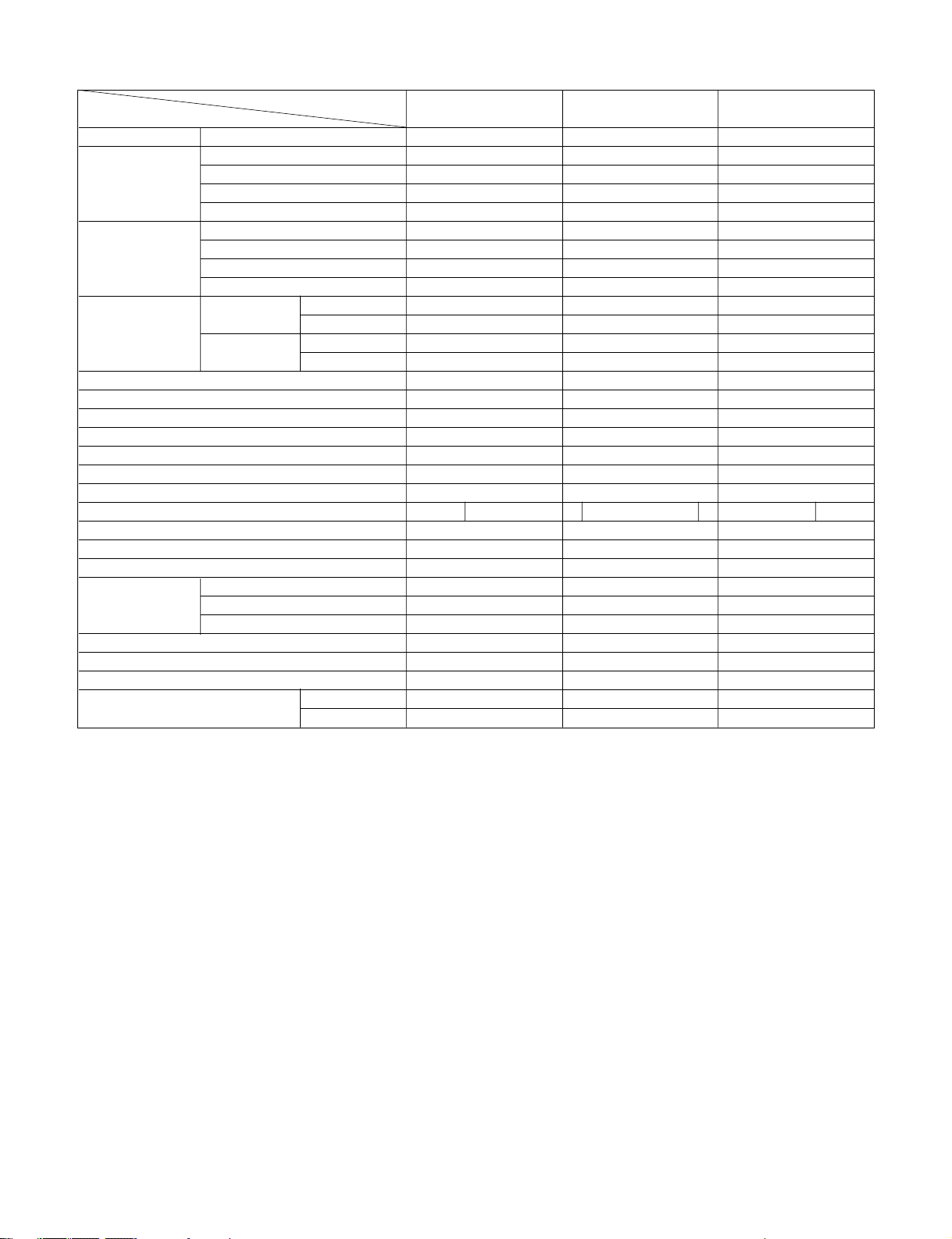
MODELS
ITEMS
POWER SUPPLY
COOLING CAPACITY (Bru/h)
INPUT (W)
RUNNING CURRENT (A)
E.E.R. (Btu/h.W)
HEATING CAPACITY (Bru/h)
INPUT (W)
RUNNING CURRENT (A)
COP(W/W)
OPERATING COOLING INDOOR (°C)
TEMPERATURE OUTDOOR (°C)
HEATING INDOOR (°C)
OUTDOOR (°C)
REFRIGEANT(R-22) CHARGE(g)
EVAPORATOR
CONDENSER
FAN, INDOOR
FAN, OUTDOOR
FAN SPEEDS (FAN/COOLING/HEATING)
FAN MOTOR
OPERATION CONTROL
ROOM TEMP. CONTROL
CONSTRUCTION
ELECTRIC HEATER
PROTECTOR COMPRESSOR
FAN MOTOR
ELECTRIC HEATER
POWER CORD
DRAIN SYSTEM
NETWEIGHT(lbs/Kg)
DIMENSION (W*H*D) (inch)
(mm)
LP090HED LP120HED LP150HED
1Ø, 230/208V, 60Hz 1Ø, 230/208V, 60Hz 1Ø, 230/208V, 60Hz
9,100/8,900 12,100/11,800 14,300/14,100
775/760 1,090/1,065 1,460/1,440
3.7/3.9 5.0/5.4 6.5/7.3
11.7/11.7 11.1/11.1 9.8/9.8
8,200/8,000 10,900/10,700 13,500/13,300
705/690 970/950 1,275/1,255
3.2/3.5 4.4/4.8 5.8/6.3
3.4/3.4 3.3/3.3 3.1/3.1
26.7 (DB) 19.4(WB) 26.7 (DB) 19.4(WB) 26.7 (DB) 19.4(WB)
35 (DB) 23.9(WB) 35 (DB) 23.9(WB) 35 (DB) 23.9(WB)
21.1 (DB) 15.6(WB) 21.1 (DB) 15.6(WB) 21.1 (DB) 15.6(WB)
8.3 (DB) 6.1(WB) 8.3 (DB) 6.1(WB) 8.3 (DB) 6.1(WB)
860(30.3 OZ) 815(28.7 OZ) 1,050(37.0 OZ)
2 ROE 10 STACKS 2 ROE 10 STACKS 2 ROE 10 STACKS
2 ROE 14 STACKS 3 ROE 17 STACKS 2 ROE 14 STACKS
Cross Flow Fan Cross Flow Fan Cross Flow Fan
Axial Fan Axial Fan Axial Fan
2/2/2 2/2/2 2/2/2
4 POLES 4 POLES 4 POLES
MANUAL TYPE MANUAL TYPE MANUAL TYPE
THERMISTOR THERMISTOR THERMISTOR
SLID IN-OUT SLID IN-OUT SLID IN-OUT
3.5KW, 230V 3.5KW, 230V 3.5KW, 230V
EXTERNAL OVERLOAD PROTECTOR EXTERNAL OVERLOAD PROTECTOR EXTERNAL OVERLOAD PROTECTOR
INTERNAL THERMAL PROTECTOR INTERNAL THERMAL PROTECTOR INTERNAL THERMAL PROTECTOR
FUSE LINK, BIMETAL THERMOSTAT FUSE LINK, BIMETAL THERMOSTAT FUSE LINK, BIMETAL THERMOSTAT
1.6m(3 WIRE WITH GROUDING) 1.6m(3 WIRE WITH GROUDING) 1.6m(3 WIRE WITH GROUDING)
SPLASHED BY FAN SLINGER SPLASHED BY FAN SLINGER SPLASHED BY FAN SLINGER
94/42.7 99/44.7 103/46.7
31
31
41
/
32*15
/
32*19
27
/
32 41
31
/
32*15
31
/
32*19
27
/
32 41
31
/
32*15
31
/
32*19
27
/
32
1066*406*505 1066*406*505 1066*406*505
—4—
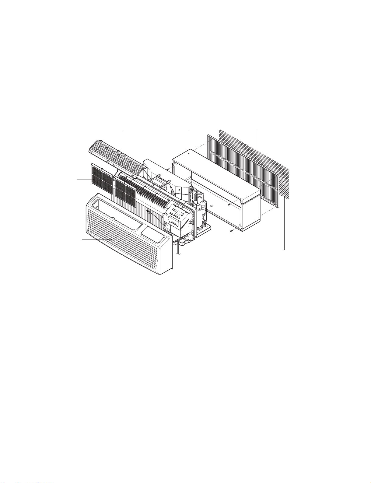
1.2 FEATURES AND BENEFITS
The PTAC has many features, some of which are different than those found on conventional PTAC units. The servicer must be
familiar with these features in order to properly service the unit.
THE SLEEVE AND THE REAR GRILLE
(Available as an option)
REAR GRILLE
(Aluminum Rear Grille)
AIR FILTER
VERTICAL AIR DEFLECTOR
(Horizontal Louver)
SLEEVE ASSEMBLY
(Including Aluminum Rear Grille)
INDOOR
INLET GRILLE
(Air Intake)
EXPANDED METAL GRILLE
(Superior for a performance)
• IIR (Infinite Impulse Response)
The IIR function senses the temperature several times per second and makes micro-adjustments several times per
• Compressor Restart Delay
This feature extends the overall life of compressor by preventing the short-cycling of the air-conditioner. When the compressor
restarts, LG PTAC is designed to give a minimum of three minutes to have a time of equalizing the refrigerant pressures for
optimizing cycling.
• Fan-Only Setting - High/Low
The fan can run at HIGH or LOW speed without COOLING or HEATING to provide air circulation and ventilation.
• Indoor Fan Speed Selections - High/Low
The fan can run at HIGH or LOW speed for either COOLING or HEATING.
• Two Fan motors
The unit has two fan motors to provide quiet operation and maximum efficiency.
• LED Diagnostics
All units have this feature indicating the problem when the unit is not operating properly with easy-to-read diagnostics. For
example, 1 blink every 2 seconds indicates compressor failure.
—5—

• Indoor Filters
The unit uses two indoor filters which slide in and cut easily. The filters may be cleaned by washing and brushing without
removing the front grille.
• Rotary Compressor
The unit uses a rotary compressor for quiet, reliable operation and long life.
• 2 Position Discharge Grille
The discharge grille can provide air flows upward at an angle of 40 off vertical or 15 degree off vertical. The angle is changed
by removing the front grille and 4 screws that fasten the discharge grille to the front grille and rotating the louvers to an
alternate position.
• Indoor Room Freeze Protection
When the unit senses the room temperature falls to less than 40° F the unit activates the fan motor and either the electric
resistance heater or the hydronic heater to prevent pipes or fixtures from freezing. This also overrides front desk control of the
unit mounted or wall mounted controls.
• Door Switch/Occupancy Sensor
The unit is capable of accommodating a field installed door switch and occupancy sensor to operate the energy management
feature. For additional information, refer to the unit operation section.
• Compressor Overload Protection
This feature prevents the damage of the compressor by sensing the indoor tube temperature in heating. If the indoor
temperature is over 130˚ F, the outdoor fan will be switched off and back on when the temperature drops below 120˚ F.
• Outdoor Air Temperature Switchover
This will effectively change the unit from heat pump mode to total electric resistance heat.
• Temperature limits
The unit is programmed to provide both heating and cooling temperature limits by dip switches on control panel from 50˚ Fto
90˚ F. Temperature limits help to prevent overheating and overcooling and reduce energy costs.
• Condensate Drain Valve
The unit has a condensate drain valve to prevent water from collecting or freezing in the basepan.
• Quick Heater Recovery
The unit is designed to operate the electric heater to warm the room to the temperature set point as soon as heat pump cycle
is on in heating. This feature has an advantage of reducing the time to reach the set point and improving the temperature
increase for better comfort.
• Reverse Cycle Defrosting - (PTHDs only)
The unit will activate the reverse cycle defrost when the outdoor coil temperature has remained at a cold temperature to form
the ice on the coil.This ice will reduce airflow though the coil and will also reduce the efficiency of unit. The LG PTHP will
employ an active reverse cycle defrost function to melt the ice off the outdoor coil for insuring room comfort conditions and
savings from extended operation.
• High Temperature Heat Pump Operation Protection
The compressor will be switched off to prevent damage when the heat pump is operated in high outdoor temperatures.
• Remote Thermostat Control
Each unit is built to be operated from any standard 4 or 5 wire remote-mounted thermostat, if desired. The unit has a built-in
low voltage power source which can accommodate a large variety of thermostat choices-manual, auto changeover, or
programmable. A remote thermostat can also be added to any installed unit.
• Zone Sensor
Occupants enjoy ultimate comfort with consistent climate control. Attach an optional, inexpensive remote Zone Sensor to
exactly match the functions of the PTAC without disabling any features.
—6—
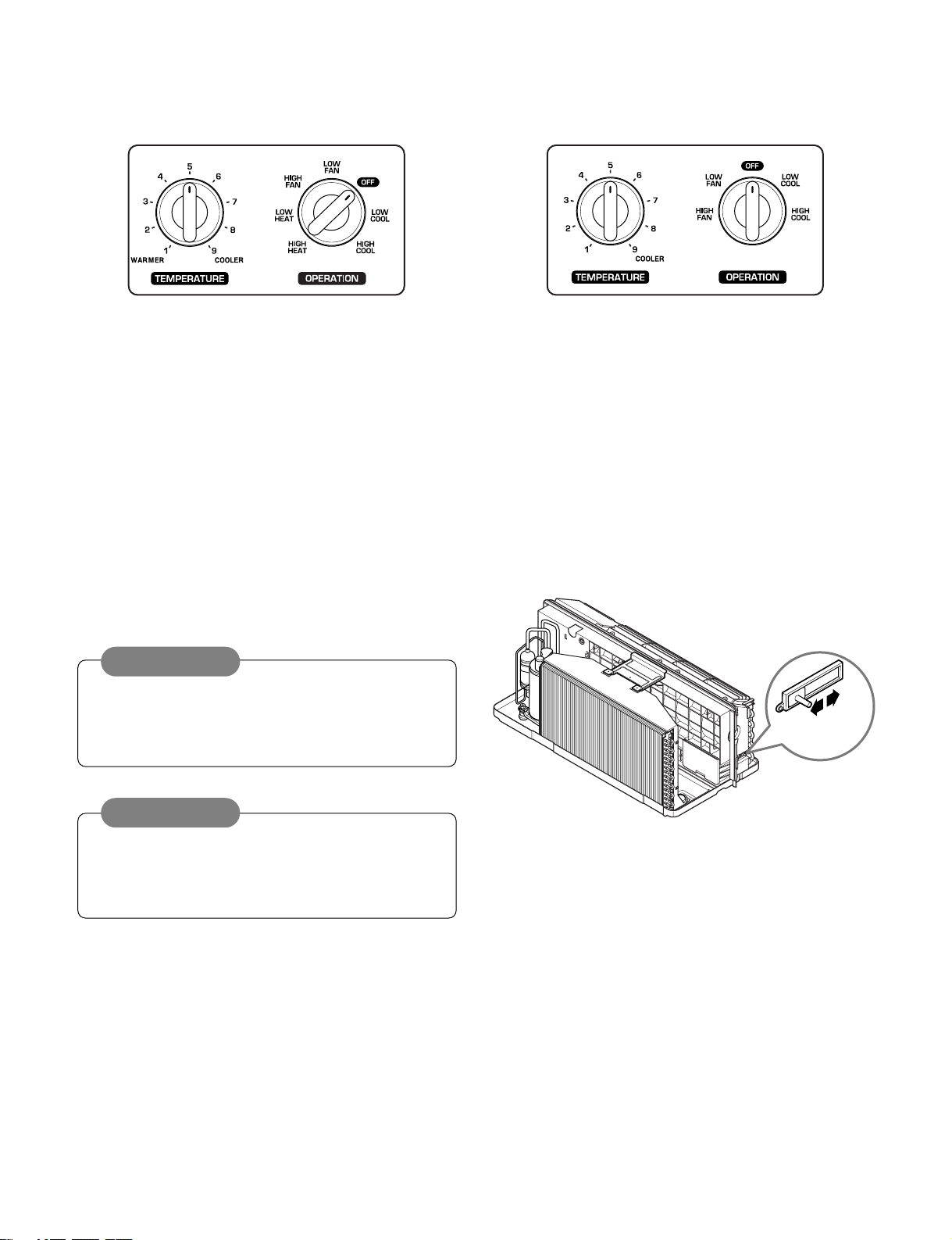
1.3 CONTROL LOCATIONS
VENT
OPEN
VENT
CLOSE
• OPERATION
ELECTRIC HEATING MODEL COOLING ONLY MODEL
TEMPERATURE CONTROL
Set the Thermostat control to the desired temperature
mark 5 (the mid-point is a good starting position). If the
room temperature is not satisfactory after a reasonable
time, adjust the control to a cooler or warmer setting, as
appropriate.
• VENTILATION
The ventilation lever is located to the lower left side of the unit.
The ventilation lever must be in the CLOSE position in order
to maintain the best cooling conditions.
When fresh air is necessary in the room, set the ventilation
lever to the OPEN position.
The damper is opened and outdoor air is drawn into the room.
This will reduce the cooling or heating efficiency.
CAUTION
When the air conditioner has performed a cooling or
heating operation and is turned off or set to the fan
position, wait at least 3 minutes before resetting to the
cooling operation.
OPERATION MODE SELECTOR
OFF Turns air conditioner off.
LOW FAN Low speed fan operation without cooling.
HIGH FAN High speed fan operation without cooling.
LOW COOL Cooling with the low speed fan operation.
HIGH COOL Cooling with the high speed fan operation.
LOW HEAT Heating with the low speed fan operation.
HIGH HEAT Heating with the high speed fan operation.
NOTE
A slight heat odor may come from the unit when first
switching to HEAT after the cooling season is over.
This odor, caused by fine dust particles on the heater, will
disappear quickly. This is harmless.
—7—
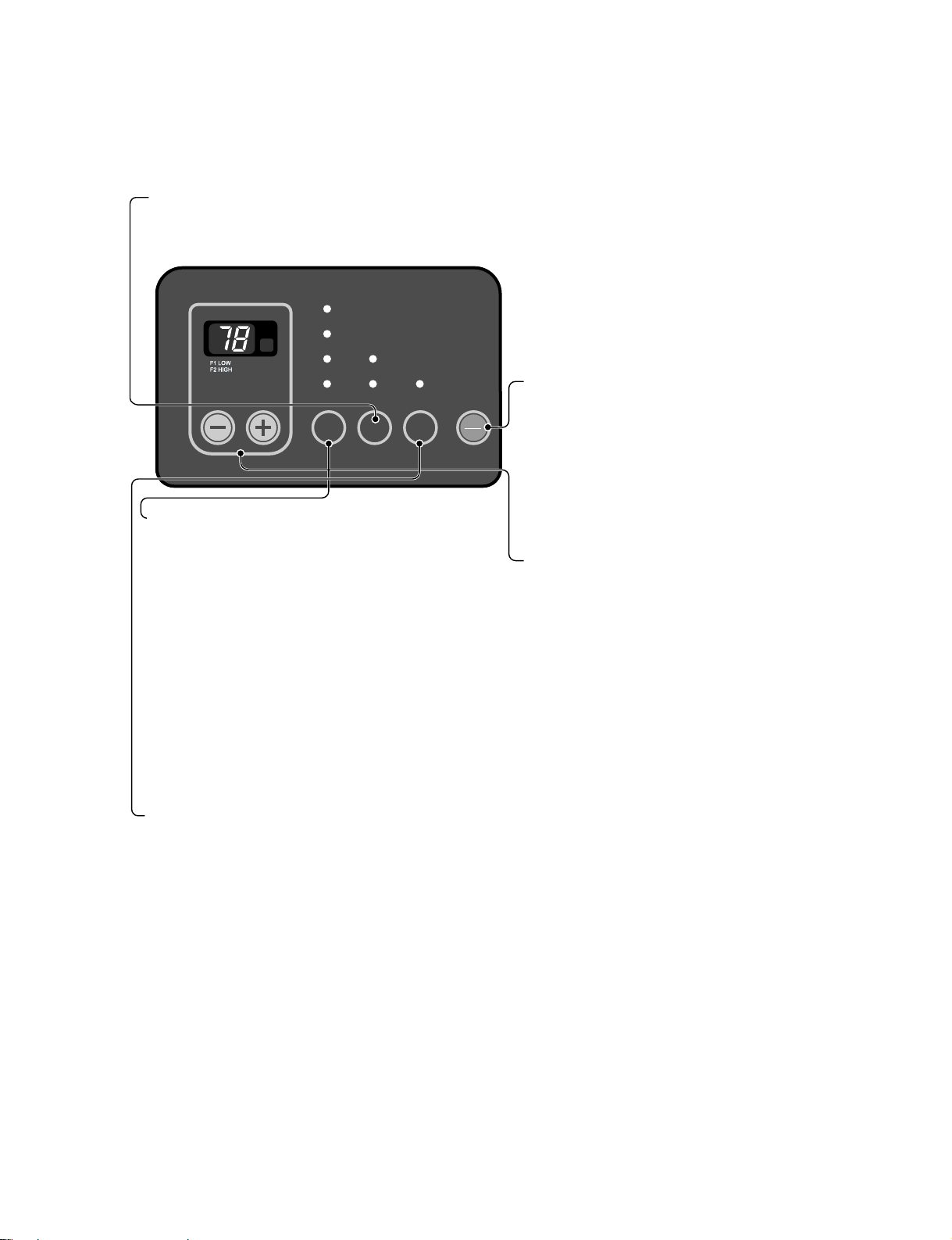
• ELECTRONIC CONTROLS
TEMP
MODE
HEAT
E/SAVE
FANFAN
COOLCOOL
HIGHHIGH
LOWLOW TIMERTIMER
FAN TIMER
'
F
ON
OFFONOFF
POWER
MODE
-
Push this button to cycle through the modes from COOL → FAN
→ HEAT→ COOL.
- COOL
• Fan runs continually for normal cooling operation.
- ENERGY SAVER
• The fan stops when the compressor stops cooling.
Approximately every 3 minutes the fan will turn on and the unit
will check the room air temperature to determine if cooling is
needed.
- FAN
• Fan operation without heating or cooling.
- HEAT
• Fan runs continually for normal heating operation.
TIMER
- SHUT-OFF TIME
• You will usually use shut-off time while you sleep.
• If unit is running, use Timer to set number of hours until shut-off.
• For your sleeping comfort, once Time is set, the Temperature setting will raise 2° F after 30 minutes, and once again
after another 30 minutes.
• Push Timer to cycle through the settings from 1 Hour → 2 Hours → ... → 12 Hours maximum.
TEMPERATURE SETTING
• Use this button to automatically control the
temperature of the room.
The temperature can be set within a range of
54° F to 86° F by increments of 2° F.
• The setting appears in the display.
FAN SPEED
• Every time you push this button, it cycles through the settings as follows:
{High(F2) → Low(F1) → High(F2) → Low(F1)}
• To turn the air conditioner ON, push this button.
To turn the air conditioner OFF, push the button
again.
• This button takes priority over any other button.
The controls will look like one of the following.
—8—
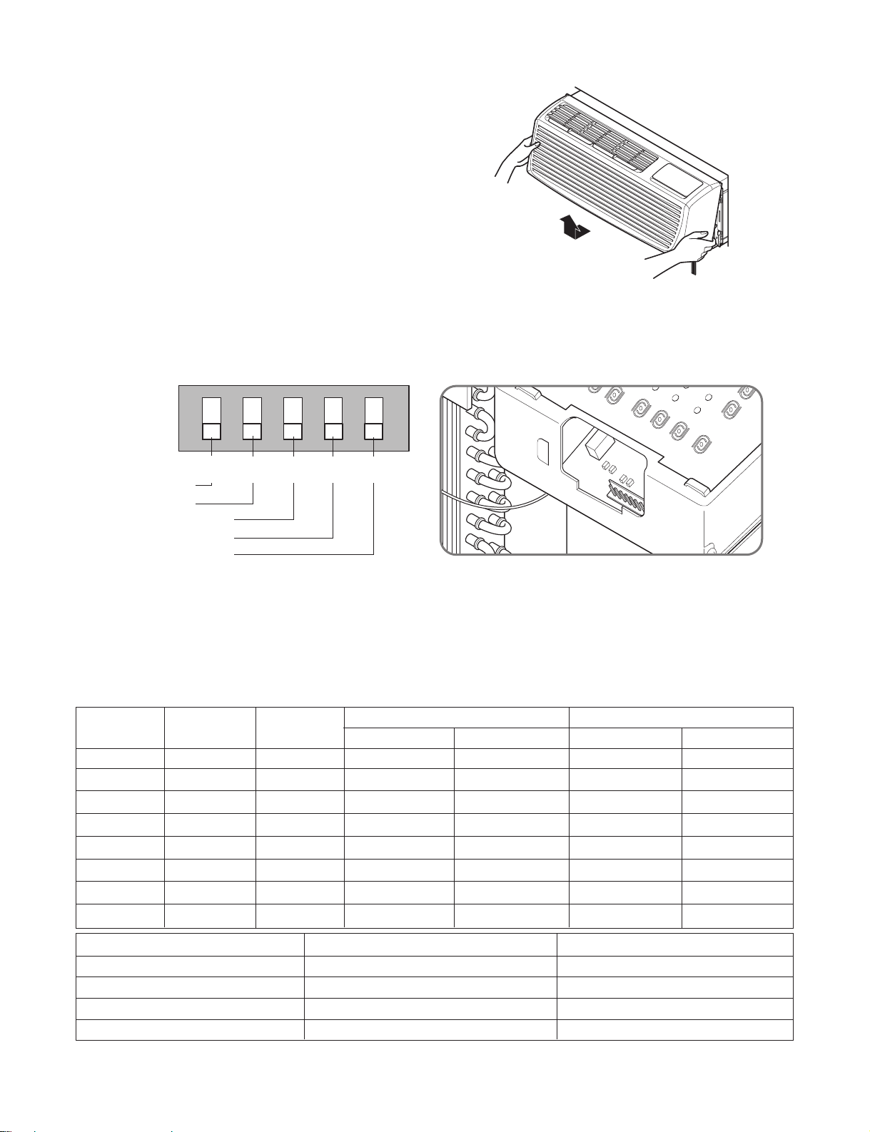
1.4 ADDITIONAL CONTROLS
ON
ONREMOTE
OFF
ON ON ON
Remote/Local
Energy Saver
Temperature Limit 1
Temperature Limit 2
Temperature Limit 3
LOCALLOCAL
1
OFF
OFF
2
OFF
OFF
3
OFF
OFF
4
OFF
OFF
5
LOCAL
1
OFF2OFF3OFF4OFF
5
LOCALLOCAL
1
OFF
OFF
2
OFF
OFF
3
OFF
OFF
4
OFF
OFF
5
LOCAL
1
OFF2OFF3OFF4OFF
5
• REMOVING THE FRONT GRILLE
Additional controls are available after removing the front
grille and option cover of control box.
To remove the front grille, pull out the bottom of front
grille and then lift up.
To replace the front grille, place the tabs over the top of
the unit and push the bottom of front grille until the clips
snap into place.
• ADDITIONAL CONTROLS
The additional controls are located behind the option cover of control box. The standard settings will be in the OFF position.
The authorized service man has to check switches and ensure the switches are in the desired position.
• TEMPERATURE LIMITING
Temperature Limiting can save money by limiting the lowest temperature for cooling and the highest temperature for heating.
The temperature limiting is controlled by dip switches #1 - #3.
This temperature limiting is not available with the Remote Wall Thermostat.
Temperature Temperature Temperature
Limit #1 Limit #2 Limit #3
OFF OFF OFF 54° F (12.2° C) 86° F (30.0° C)
ON OFF OFF 56° F (13.3° C)
OFF ON OFF 58° F (14.4° C)
ON ON OFF 60° F (15.5° C)
OFF
ON OFF ON 64° F (17.7° C)
OFF ON ON 66° F (18.9° C) 74° F (23.3° C)
ON ON ON 68° F (20.0° C) 72° F (22.2° C)
OFF ON 62° F (16.6° C)
#6
ON
ON
Cooling Operation
Heating Operation
Lowest Temp. Highest Temp. Lowest Temp. Highest Temp.
#7
OFFOFF
ONOFF
OFF
ON
86° F (30.0° C)
86° F (30.0° C)
86° F (30.0° C)
86° F (30.0° C)
86° F (30.0° C)
86° F (30.0° C)
86° F (30.0° C)
54° F (12.2° C)
54° F (12.2° C)
54° F (12.2° C)
54° F (12.2° C)
54° F (12.2° C)
54° F (12.2° C)
54° F (12.2° C)
54° F (12.2° C)
Unit Type
Cooling+Electric Heater+Heat Pump
Cooling+Electric Heater
Heat Pump Only
Cooling Only
86° F (30.0° C)
84° F (28.9° C)
82° F (27.8° C)
80° F (26.7° C)
78° F (25.5° C)
76° F (24.4° C)
—9—
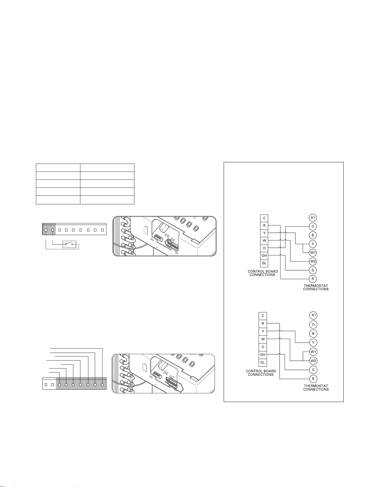
• REMOTE/LOCAL CONTROL
GL GH O W Y R CLO LI
Front Desk Switch
LO LI GL GH O W Y R C
Low Fan
High Fan
Reversing Valve
Heater
Compressor
24 Volt-L
24 Volt-N
Wiring Schematic for
Remote Heat Pump
Wiring Schematic for
Straight Cool Unit.
When remote/local switch #1 is on, it allow the unit to operate by the control of Remote Wall Thermostat.
The unit control by knobs are not available.
• ENERGY SAVER
The energy saver switch #2 is on. This switch is set at cycle fan to provide continuous fan operation in cool or heat modes.
When the switch is off the continuous fan allows continuous circulation of room air and make the more balanced temperature
of the room. When the switch is on the fan is on or off with the compressor or with the heater.
• FRONT DESK CONTROL
When the pair wire is connected to the connector LO and LI, the unit can be turned ON or OFF with a switch located at the
Front Desk Control panel. When the front desk switch is ON, the fan operate according to the condition of setting without
working compressor and heater. When the front desk switch is OFF, the unit can operate according to the setting of controls.
Wire # AWG Maximum Length
#22
600 ft (180 m)
#20 900 ft (270 m)
#18 1500 ft (450 m)
#16 2000 ft (610 m)
Molex Housing Spec 396-06V
• REMOTE WALL THERMOSTAT
When the wires are connected, the unit will be controlled by a remote wall
thermostat.
The thermostat connections supply the 24 Volt AC. When you install the
digital/electronic thermostat, you must set it to the 24 Volt AC. See the
installation Instruction in this manual for the Remote Wall Thermostat.
Note: The following figures show wiring
schematics for heat pump and straight cool
units with electric heat, respectively.
Molex Housing Spec 396-07V
—10—
40˚
15˚
Screws
2. DISASSEMBLY INSTRUCTIONS
— Before the following disassembly, POWER SWITCH is set to OFF and disconnected the power cord.
2.1 MECHANICAL PARTS
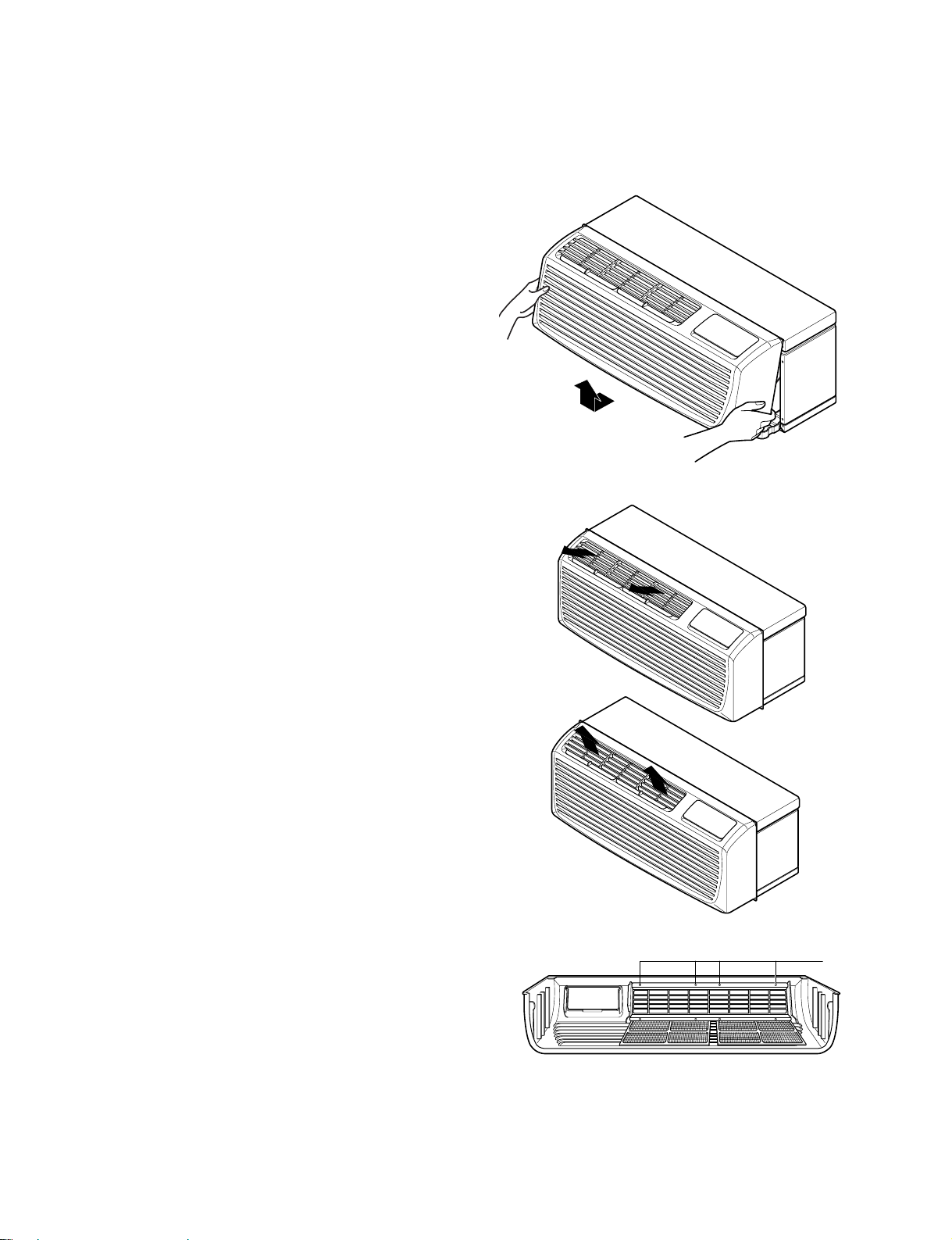
2.1.1 FRONT GRILLE
1. Remove the front grille. (See Figure 1)
2. To remove the front grille, pull out the bottom of
the front grille and then lift up.
Re-install the component by referring to the
removal procedure.
3. To replace the front grille, place the tabs over the
top of the unit and push the bottom of front grille
until the clips snap into place.
Figure 1
• This Room Air Conditioner (PTAC) discharges air
from the top of the unit through reversible, 2-position
discharge grille louvers. The unit is shipped from the
factory with the discharge grille louvers at an angle
of 40˚ off vertical. In the alternate position, the
louvers will be at an angle of 15˚ off vertical.
To adjust air direction, remove the front grille.
Remove the 4 screws that fasten the discharge grille
to the front grille.
Flip the discharge grille 180°, then reattach the
discharge grille to the front grille with 4 screws.
—11—
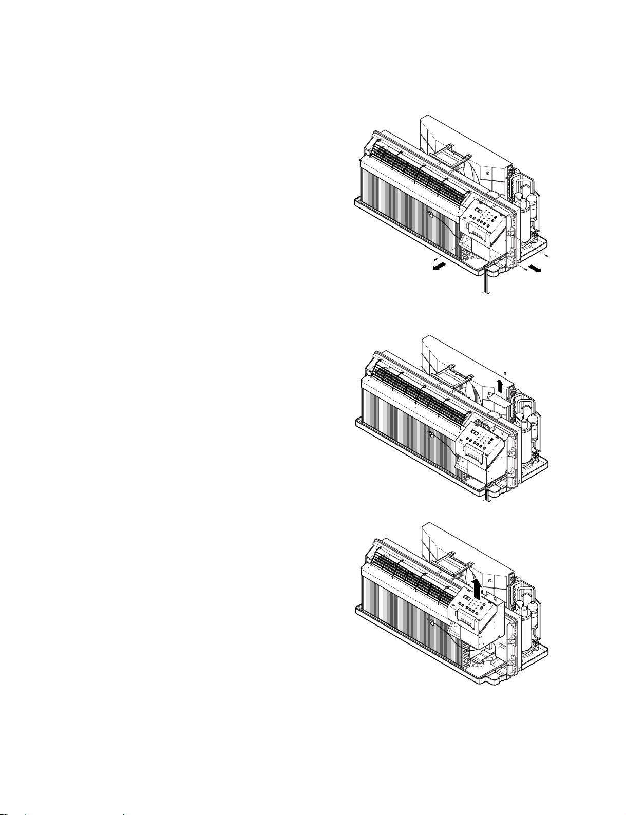
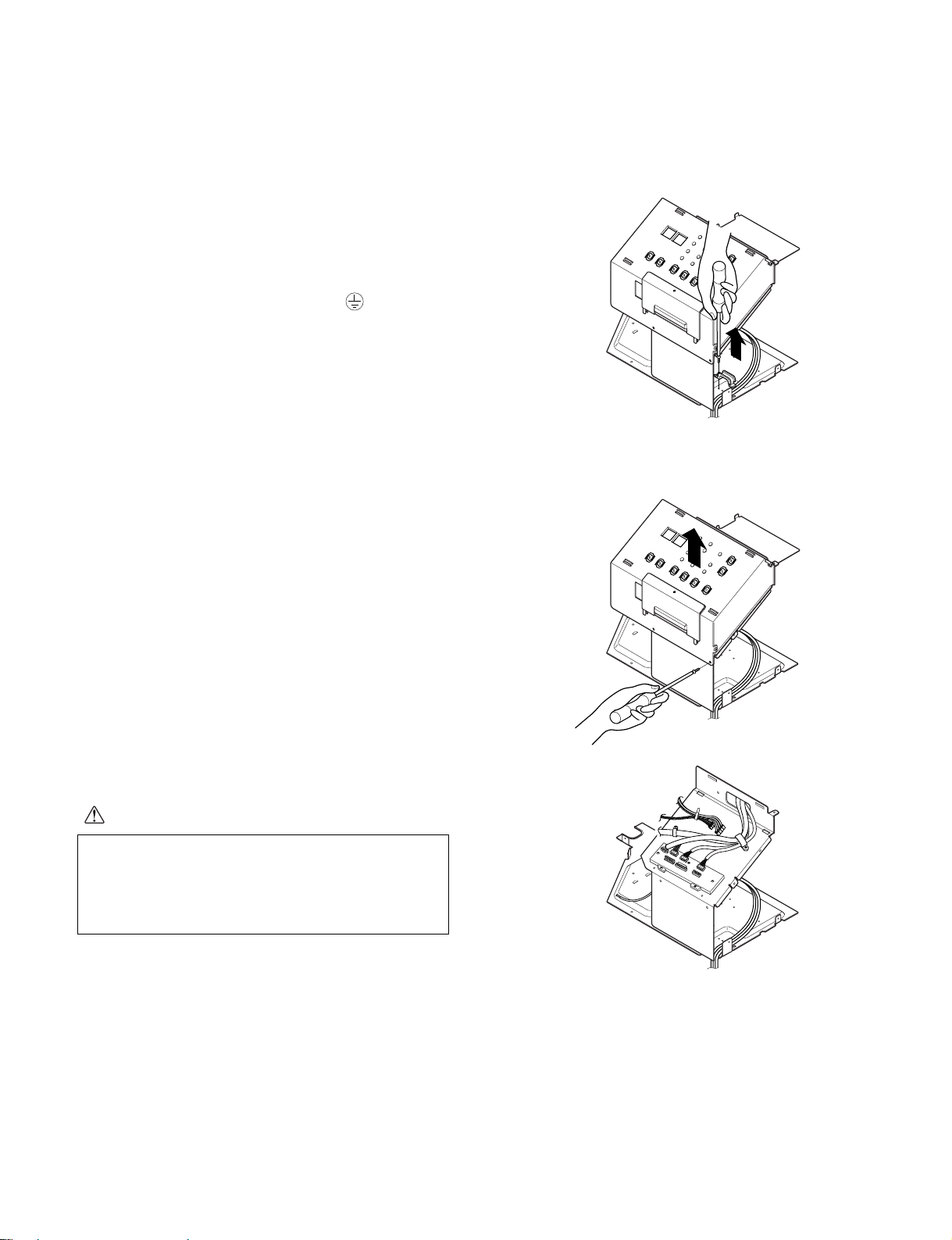
2.1.2 CONTROL BOX
1. Remove the front grille. (Refer to section 2.1.1)
2. Remove the two screws which fasten the control
box. (See Figure 2)
3. Pull the control box from the Air guide.
4. Remove the control box cover. (See Figure 3)
5. Disconnect wire housings on the control box.
Figure 2
6. Pull the control box assembly out from the unit.
(See Figure 4)
7. Re-install the components by referring to the
removal procedure.
Figure 3
Figure 4
—12—
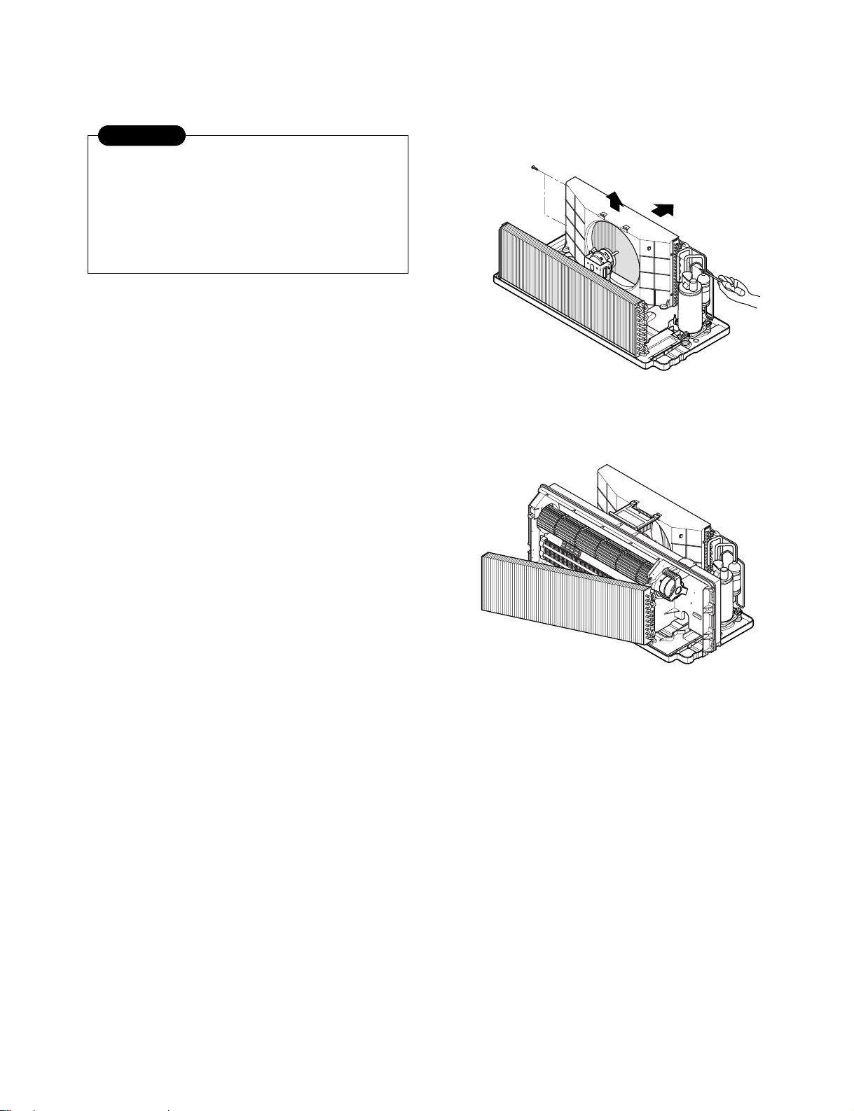
2.2 AIR HANDLING PARTS
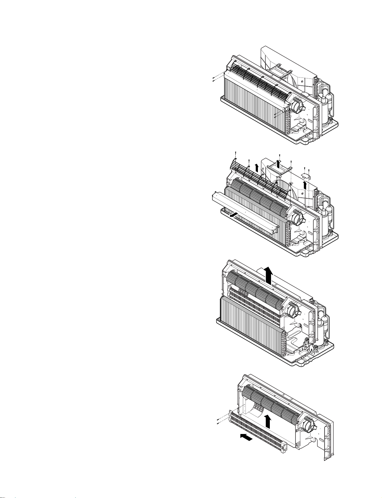
2.2.1 ELECTRIC HEATER
(ELECTRIC HEATER MODEL ONLY)
1. Remove the front grille.(Refer to section 2.1.1)
2. Remove the control box assembly.
(Refer to section 2.1.2)
3. Remove the 4 screws which fasten the Evaporator.
(See Figure 5)
4. Remove the top cover assembly, net steel, brace.
(See Figure 6)
Figure 5
5. Remove the 6 screws which fasten the Air-guide.
6. Pull the Air-guide assembly out from the unit.
(See Figure 7)
7. Remove the 2 screws which fasten the electric
heater in the left hand side.
8. Pull the electric heater towards left for a while and
then lift up vertically to disassemble it completely
from Air guide.
Figure 6
Figure 7
—13—
Figure 8
2.2.2 CROSS FLOW FAN
1. Remove the front grille. (Refer to section 2.1.1)
2. Remove the control box assembly.
(Refer to section 2.1.2)
3. Remove the Air-Guide Assembly from the unit.
(Refer to section 2.2.1)
4. Loosen the screw on the cross flow fan.
(See Figure 9)
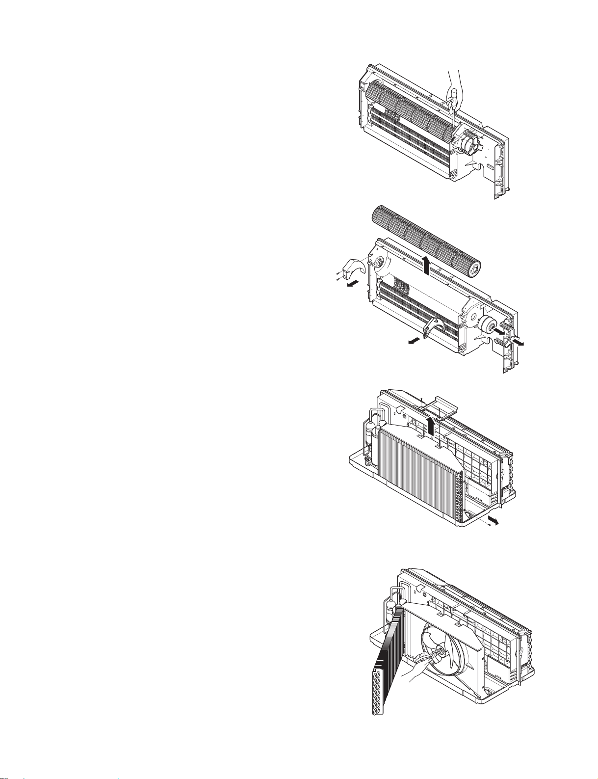
5. Remove the 4 screws which fasten the indoor
motor and the earth wire. (See Figure 10)
6. Remove the supports on both sides.
7. Pull the cross flow fan out from the air-guide.
8. Re-install the components by referring to the
removal procedure.
Figure 9
2.2.3 AXIAL FAN
1. Remove the brace.
2. Remove the 4 screws which fasten the condenser
with the shroud and the basepan. (See Figure 11)
3. Remove the condenser sideways carefully.
4. Remove the clamp which secures the fan with
pliers.(See Figure 12)
5. Remove the axial fan.
6. Re-install the components by referring to the
removal procedure.
Figure 10
Figure 11
—14—
Figure 12
2.2.4 SHROUD
1. Remove the axial fan. (Refer to section 2.2.3)
2. Remove the 4 screws which fasten the condenser
with the shroud and the basepan. (See Figure 11)
3. Remove the shroud.
4. Re-install the component by referring to the
removal procedure.
2.3. ELECTRICAL PARTS
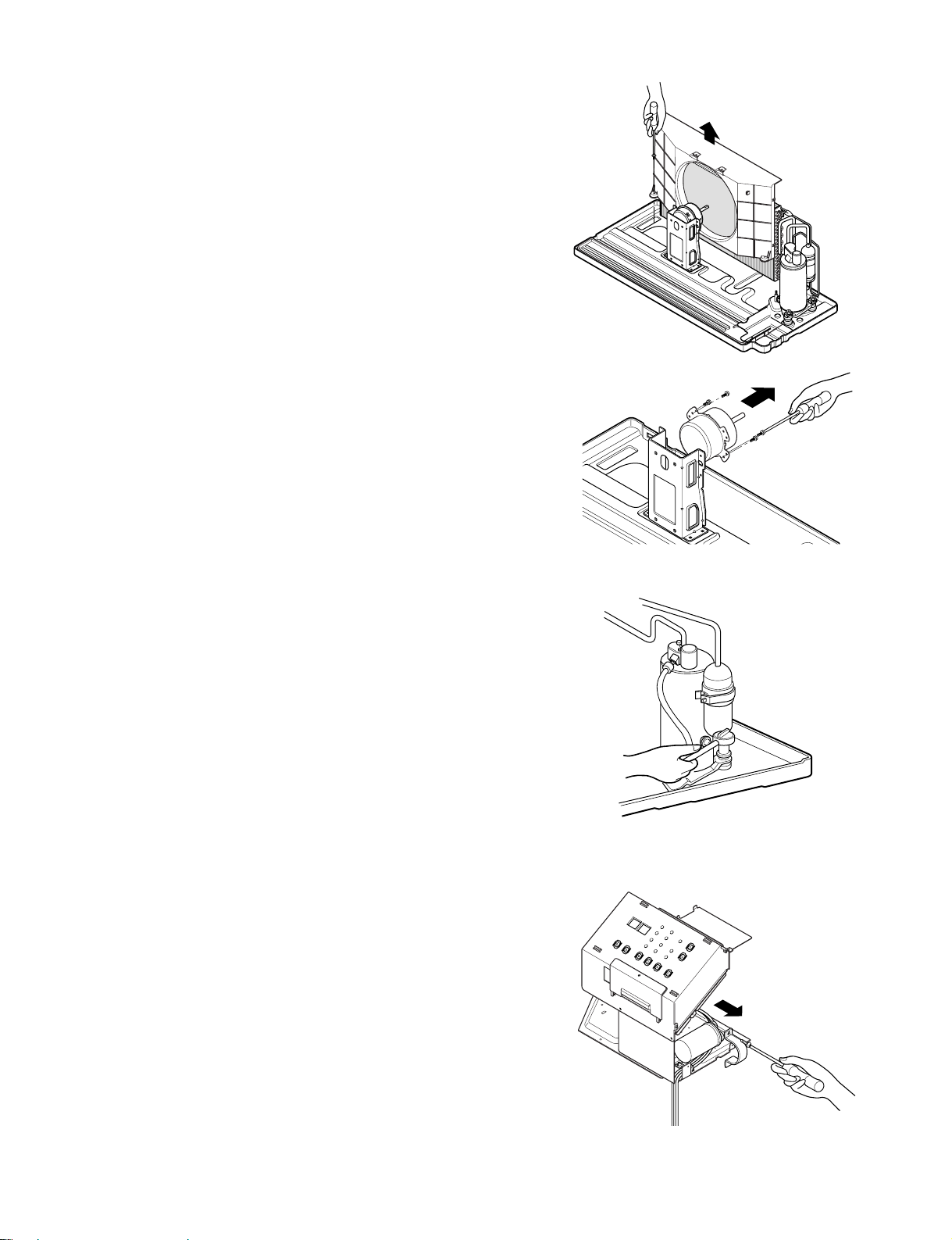
2.3.1 OUTDOOR MOTOR
1. Remove the clamp cord and disconnect a wire
housing in control box. (Refer to section 2.1.2)
2. Remove the axial fan. (Refer to section 2.2.3)
3. Remove the 2 screws which fasten the motor.
(See Figure 12)
4. Remove the motor
5. Re-install the component by referring to the
removal procedure, above.
2.3.2 INDOOR MOTOR (Refer to section 2.2.2)
2.3.3 COMPRESSOR
1. Discharge the refrigerant system using a
refrigerant recovery system.
If there is no valve to attach the recovery system,
install one (such as a WATCO A-1) before venting
the refrigerant. Leave the valve in place after
servicing the system.
2. Disconnect the 3 leads from the compressor.
3. After purging the unit completely, unbraze the
suction and discharge tubes at the compressor
connections.
4. Remove the 3 nuts and the 3 washers which
fasten the compressor. (See Figure 15)
5. Remove the compressor.
6. Re-instill the components by referring to the
removal procedure, above.
Figure 13
Figure 14
Figure 15
2.3.4 CAPACITOR
1. Remove the control box. (Refer to section 2.1.2)
2. Remove 1 screw and disconnect the leads which
connected to the box type capacitor.
(See Figure 16)
3. Remove 1 screw and the clamp which fastens the
can-type capacitor.
4. Disconnect all the leads of capacitor terminals.
5. Re-install the components by referring to the
removal procedure, above.
Figure 16
—15—
2.3.5 POWER CORD
1. Remove the control box. (Refer to section 2.1.2)
2. Disconnect the grounding screw from the control
box.
3. Disconnect 2 receptacles.
4. Remove a screw which fastens the clip cord.
5. Separate the power cord from the control box.
(See Figure 17)
6. Re-install the component by referring to the
removal procedure, above.
(Use only one ground-marked hole for ground
connection.)
7. If the supply cord of this appliance is damaged, it
must be replaced by an exact replacement part.
(The special cord means the cord which has the
same specification marked on the supply cord
fitted to the unit.)
2.3.6 P.C.B.
1. Remove the escutcheon.
2. Remove the two knobs.
3. Remove the 2 screws which fasten P.C.B. cover.
4. Disconnect all the leads which connected to the
P.C.B.
5. Remove the two screws which fasten the P.C.B.
board.
6. Re-install the components by referring to the
removal procedure, above.
Figure 17
WARNING
After servicing control box ,make sure that AC and DC
wires are separated and tied up properly.
The wires should also be pressed a little downwards to
prevent touching it to the display pcb.
Figure 18
—16—
2.4 REFRIGERATION CYCLE
CAUTION
Discharge the refrigerant system using a
refrigerant recovery system.
If there is no valve to attach the recovery system,
install one (such as a WATCO A-1) before
venting the refrigerant. Leave the valve in place
after servicing the system.
2.4.1 CONDENSER
1. Remove the brace and the shroud.
(Refer to section 2.2.2)
2. Remove the 4 screws which fasten the shroud.
(Refer to section 2.2.2)
3. Push forward the shroud and remove the 2 screws
which fasten the condenser with the basepan.
4. After discharging the refrigerant completely,
unbraze the interconnecting tube at the condenser
connections.
5. Remove the condenser.
6. Re-install the components by referring to notes.
(See Figure 19)
Figure 19
2.4.2 EVAPORATOR
1. Remove the front grille. (Refer to section 2.1.1)
2. Discharge the refrigerant completely.
3. Remove the control box assembly.
(Refer to section 2.1.2)
4. Remove the 4 screws which fasten the evaporator
at the left side and the right side.
5. Move the evaporator sideward carefully and then
unbraze the interconnecting tube at the evaporator
connectors.
6. Remove the evaporator.
7. Re-install the components by referring to notes.
(See Figure 20)
2.4.3 CAPILLARY TUBE
1. After discharging the refrigerant completely,
unbraze the interconnecting tube at the capillary
tube.
2. Remove the capillary tube.
3. Re-install the components by referring to notes.
Figure 15
Figure 20
—17—
 Loading...