

Page 1
OWNER'S MANUAL
AIR
CONDITIONER
ENGLISH ESPAÑOL FRANÇAIS
Please read this manual carefully before operating
your set and retain it for future reference.
TYPE : Room Air Conditioner
P/NO : MFL67646802
Rev.01_072516
http://www.lghvac.com
www.lg.com
Page 2

2 Room Air Conditioner
Packaged Terminal Air Conditioner/Heat Pump Owner's Manual
TABLE OF CONTENTS
Safety Precautions..........................3
Before Operation.............................7
Introduction ....................................8
Electrical Safety ..............................9
Installation .....................................11
Control Locations .........................13
Maintenance and Service ............19
FOR YOUR RECORDS
Write the model and serial numbers here:
Model #
Serial #
You can find them on quality label and front of base pan of
each unit.
Dealer's Name
Date Purchased
Staple your receipt to this page in the event you need it
to prove date of purchase or for warranty issues.
READ THIS MANUAL
Inside you will find many helpful hints on how to use and
maintain your air conditioner properly. Just a little
preventive care on your part can save you a great deal of
time and money over the life of your air conditioner.
You'll find many answers to common problems in the chart
of troubleshooting tips. If you review our chart of
Troubleshooting Tips first, you may not need to call for
service at all.
PRECAUTION
• Contact an authorized service technician for repair or
maintenance of this unit.
• Contact the installer for installation of this unit.
• The air conditioner is not intended for use by young
children or invalids without supervision.
• Young children should be supervised to ensure that
they do not play with the air conditioner.
• When the power cord is to be replaced, replacement
work shall be performed by authorized personnel
only using only genuine replacement parts.
• Installation work must be performed in accordance
with the National Electric Code by qualified and
authorized personnel only.
Page 3
Ownerʼs Manual 3
ENGLISH
Safety Precautions
Safety Precautions
WARNING
WARNING
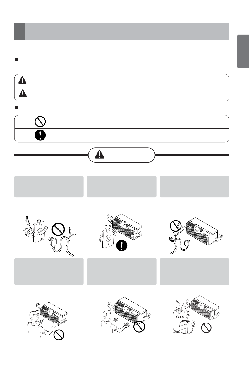
n Installation
Don't do this!
Be sure to follow the instruction.
Donʼt use a power cord, a
plug, or a loose socket
which is damaged.
• It may cause a fire or electrical
shock.
Always plug into a grounded
outlet.
• It may cause a fire or electrical
shock.
Do not modify or extend the
power cord length.
• It will cause electric shock or fire
due to heat generation.
Do not disassemble or
modify products.
• It may cause failure and
electric shock.
Be caution when unpacking
and installing.
• Sharp edges may cause
injury.
Do not use the power cord near
flammable gas or combustibles
such as gasoline, benzene,
thinner, etc.
• It may cause explosion or fire.
Following instructions must be followed to prevent injury to the user and property damages.
Incorrect operation due to ignoring instruction will cause harm or damage. The seriousness
is classified by the following indications.
This symbol indicates the possibility of death or serious injury.
CAUTION
Meanings of symbols used in this manual are as shown below.
This symbol indicates the possibility of injury or damage to properties only.
Gasolin
Page 4

4 Room Air Conditioner
Safety Precautions
n Operation
Do not place the power cord
near a heater.
• It may cause fire and electric
shock.
Do not allow water to run
into electric parts.
• It will cause failure of machine or
electric shock.
Use a soft cloth to clean. Do
not use wax, thinner, or a
strong detergent.
• The appearance of the air
conditioner may deteriorate,
change color, or develop
surface flaws.
Ventilate the room well when
using this appliance
together with a stove, etc.
• Oxygen depletion could occur.
Turn off the power and
breaker when cleaning the
unit.
• Moving parts could cause injury.
Turn off the main power
switch when not using it for
a long time.
• Prevent accidental startup and
the possibility of injury.
Unplug the unit if strange
sounds, odors, or smoke
come from it.
• It could represent a fire hazed.
Do not open the suction
inlet grill of the product
during operation.
• Otherwise, it may electrical
shock and failure.
If water enters the product, turn
off the the power switch of the
main body of appliance. Contact
service center after taking the
power plug out from the socket.
Do not place objects on the
power cord. Protect the
cord from being pinched or
damaged.
• There is danger of fire or electric
shock.
Use a dedicated circuit for
this appliance.
• An overloaded circuit is a fire
hazard.
Take the power plug out if
necessary, holding the end
of the plug and do not touch
it with wet hands.
• It may cause a fire or electrical
shock.
Thinner
Wax
Page 5

Ownerʼs Manual 5
ENGLISH
Safety Precautions
CAUTION
n Installation
Do not operate or stop the
unit by inserting or pulling
out the power plug.
• It will cause electric shock or fire
due to heat generation.
Do not damage or use an
unspecified power cord.
• It will cause electric shock or fire.
Do not operate with wet
hands or in damp
environment.
• It will cause electric shock.
Hold the plug by the end
when taking it out.
• It may cause electric shock and
damage.
When gas leaks, open the
window for ventilation
before operating the unit.
• Otherwise, it may cause an
explosion and a fire.
Never touch the metal parts
of the unit when removing
the filter.
• They are sharp and may cause
injury.
Install the product so that the noise or
exhaust from the outdoor unit may not
cause any damage to the neighbors.
• Be considerate of your neighbor.
Be sure the product is level front-to-back
and side-to-side when installing.
• It may cause vibration or water leakage.
For inner cleaning, contact an Authorized Service Center or a dealer.
Do not use harsh detergent that causes corrosion or damage on the unit.
• Harsh detergent may also cause failure of product, fire, or electronic shock.
Page 6

6 Room Air Conditioner
Safety Precautions
n Operation
Be cautious not to touch the
sharp edges when installing.
• A severe cut or other injury could result.
Avoid excessive cooling and
perform ventilation sometimes.
• Use the ventilation function to circulate
air without cooling or heating
Do not insert hands or other
objects through the air inlet or
outlet during operation.
• Electrical and moving parts could cause
shock or injury.
If the liquid from the batteries gets onto your skin or
clothes, wash it well with clean water. Do not use the
remote if the batteries have leaked.
• The chemicals in batteries could cause burns or other health
hazards.
If you eat the liquid from the batteries, brush your teeth
and see doctor. Do not use the remote if the batteries
have leaked.
• The chemicals in batteries could cause burns or other health
hazards.
Do not put a pet or house plant
where it will be exposed to direct
air flow.
• It is not good to sit in the draft.
Do not block the inlet or outlet of
air flow.
• It may cause product failure.
Use a soft cloth to clean. Do not
use wax, thinner, or a strong
detergent.
• The appearance of the air conditioner
may deteriorate, change color, or
develop surface flaws.
Do not step on the indoor/outdoor
unit and do not put anything on it.
• It may cause an injury through dropping
of the unit or falling down.
Always insert the filter securely.
Clean it every two weeks.
• Operation without filters will cause
failure.
Do not drink water drained from
the air conditioner.
• It contains every contaminant
condensed from the air and could cause
health issues.
Page 7

Ownerʼs Manual 7
ENGLISH
Before Operation
Before Operation
1. Contact an installation specialist for installation.
This is NOT a do-it-yourself project.
2. Plug in the power plug properly.
3. Use a dedicated circuit.
4. Do not use an extension cord. Consult a professional installer or electrician.
5. Do not start/stop operation by plugging/unplugging the power cord.
6. If the cord/plug is damaged, replace it with only an authorized replacement
part.
1. Being exposed to direct airflow for an extended period of time could be
hazardous to your health. Do not expose occupants, pets, or plants to direct
airflow for extended periods of time. In other words, don't sit in the draft.
2. Due to the possibility of oxygen deficiency, ventilate the room when used
together with stoves or other heating devices.
3. Do not use this air conditioner for non-specified special purposes (e.g.
preserving precision devices, food, pets, plants, and art objects). Such usage
could damage the items.
1. Do not touch the metal parts of the unit when removing the filter. Injuries can
occur when handling sharp metal edges.
2. Do not use water to clean inside the air conditioner. Exposure to water can
destroy the insulation, leading to possible electric shock.
3. When cleaning the unit, first make sure that the power and breaker are turned
off. The fan rotates at a very high speed during operation. There is a
possibility of injury if the unitʼs power is accidentally triggered on while
cleaning inner parts of the unit.
For repair and maintenance, contact your authorized service dealer.
Preparing for Operation
Usage
Cleaning and Maintenance
Service
Page 8

8 Room Air Conditioner
Introduction
This symbol alerts you to the risk of electric shock.
This symbol alerts you to hazards that could cause harm to
the air conditioner.
This symbol indicates special notes.
NOTICE
Introduction
Symbols Used in this Manual
Features
This air conditioner should be installed in accordance with the National Electric Code.
Expanded Metal Grille Should be applied for better performance in PTAC and PTHP Units.
For Installation purpose and better appearance Aluminium or Architectural grille can be applied in
PTAC and PTHP Units.
THE SLEEVE AND THE REAR GRILLE
VERTICAL AIR DEFLECTOR
(Horizontal Louver)
(Available as an option)
SLEEVE ASSEMBLY
REAR GRILLE
(Aluminum Rear Grille)
Architecture Rear Grille
AIR FILTER
FRONT GRILLE
(Air Intake)
INDOOR
EXPANDED METAL GRILLE
Page 9

Ownerʼs Manual 9
ENGLISH
Electrical Safety
Electrical Safety
Electrical Data
Use Wall Receptacle Power Supply
Standard 208/230V, 3-wire
grounding receptacle rated 15A
Standard 208/230V, 3-wire
grounding receptacle rated 20A
Standard 208/230V, 3-wire
grounding receptacle rated 30A
Standard 265V grounding
receptacle rated 20A
Standard 265V grounding
receptacle rated 30A
Use 15 AMP. time
delay fuse or 15 AMP.
Circuit breaker.
Use 20 AMP. time
delay fuse or 20 AMP.
Circuit breaker.
(2500W Heater ơ15AMP.
Circuit Breaker)
Use 30 AMP. time
delay fuse or 30 AMP.
Circuit breaker.
Use 20 AMP. time
delay fuse or 20 AMP.
Circuit breaker.
Use 30 AMP. time
delay fuse or 30 AMP.
Circuit breaker.
Never push the test button during
operation
Otherwise this plug can damaged.
This device contains chemicals, including
lead, known to the State of California to
cause cancer, birth defects, or other
reproductive harm.
Wash hands after handling.
Do not remove, modify, or immerse this plug.
If this device trips, the cause should be
corrected before further use.
The conductors inside this cord are
surrounded by shields, which monitor
leakage current.
These shields are not grounded.
Periodically examine the cord for any
damage. Do not use this product in the
event the shields become exposed.
Avoid shock hazard! This unit cannot
be serviced. Opening the tamperresistant, sealed portion of the unit
voids all warranties and performance
claims. This unit is not intended to be
an ON/OFF switch.
The shape may be different according to its model.
NOTICE
DO NOT USE AN EXTENSION CORD on 230,
208, and 208/230, 265 Volt units.
All wiring should be made in accordance with local
electrical codes and regulations.
Aluminum house wiring may pose special
problems. Consult a qualified electrician.
NOTICE
208/230V~ 265V~
Power cord may include a current interrupter device.
A test and reset button is provided on the plug case.
The device should be tested on a periodic basis by first
pressing the TEST button and then the RESET button.
If the TEST button does not trip or if the RESET button
will not stay engaged, discontinue use of the air
conditioner and contact a qualified service technician.
*In the case of 265V power cord doesn’t have current
interrupter device.
Page 10
10 Room Air Conditioner
Electrical Safety
IMPORTANT
(PLEASE READ CAREFULLY)
FOR THE USER'S PERSONAL SAFETY, THIS
APPLIANCE MUST BE PROPERLY GROUNDED
The power cord of this appliance is equipped with a
three-prong (grounding) plug. Use this with a standard
three-slot (grounding) wall power outlet to minimize
the hazard of electric shock. The customer should
have the wall receptacle and circuit checked by a
qualified electrician to make sure the receptacle is
properly grounded.
DO NOT CUT OR REMOVE THE THIRD (GROUND)
PRONG FROM THE POWER PLUG.
A. SITUATIONS WHEN THE APPLIANCE WILL BE
DISCONNECTED OCCASIONALLY
Because of potential safety hazards, we strongly
discourage the use of an adapter plug. However, if
you wish to use an adapter, a TEMPORARY
CONNECTION may be made. Use UL-listed adapter,
available from most local hardware stores.
The large slot in the adapter must be aligned with the
large slot in the receptacle to assure a proper polarity
connection.
Attaching the adapter ground terminal to the wall
receptacle cover screw does not ground the
appliance unless the cover screw is metal, and not
insulated, and the wall receptacle is grounded
through the house wiring. The customer should
have the circuit checked by a qualified electrician to
make sure the receptacle is properly grounded.
Disconnect the power cord from the adapter, using
one hand on each. Otherwise, the adapter ground
terminal might break. DO NOT USE the appliance with
a broken adapter plug.
B. SITUATIONS WHEN THE APPLIANCE WILL BE
DISCONNECTED OFTEN
Do not use an adapter plug in these situations.
Unplugging the power cord frequently can lead to an
eventual breakage of the ground terminal. The wall
power outlet should be replaced by a three-slot
(grounding) outlet instead.
USE OF EXTENSION CORDS
Because of potential safety hazards, we strongly
discourage the use of an extension cord. However, if
you wish to use an extension cord, use a CSA
certified/UL-listed 3-wire (grounding) extension cord.
Electrical Safety
Page 11

Ownerʼs Manual 11
Installation
Installation
How to Install the Unit
• Need 2 people to lift up air conditioner, it is HEAVY.
For existing sleeve, you should measure the wall sleeve
dimensions.
You can install the new air conditioner according to these
installation instructions to achieve the best performence. All
wall sleeves used to mount the new air conditioner must be in
good structural condition and have the rear grille that securely
attached to the sleeve or the flange of the sleeve to secure the
new air conditioner.
• To avoid vibration and noise, make sure the unit is installed
securely and firmly.
When installing the sleeve & Front grille, make certain there is
nothing within 21 ” back & front of sleeve & front grille, that
would interfere with heat radiation and exhaust air flow.
• Before installation, Check the insulation on the inner side of
the sleeve. If there is no insulation, place the insulation.
• Check the bottom corner's joint gap of the sleeve, If there is,
fill the gap with putty.
Dimension of air conditioner
1,066 mm
(42")
406 mm
(16")
349 mm
3
(13
/4")
536 mm
(21")
Dimension of sleeve assembly (optional)
1066 mm
(42")
Insulation
Joint Gap
349 mm
3
/4")
(13
406 mm
(16")
ENGLISH
NOTICE
To maintain the best performance
of LG PTAC
1. An insulation strip must be attached. The
insulation strip is provided with the box.
2. After assembly of sleeve & front grille, the
gap should be over 20” from both sleeve &
grille. For assembly PTAC Model refer the
diagram.
1) Take out the insulation strip from the upper packing.
2) Attach the insulation strip onto the rear upper side of the
wall sleeve.
INSULATION
COOLED
AIR
INTAKE
AIR
1/4" Bubble
of the level
Over 20"
280 mm
(11")
WALL
WALL
Insulation Strip
Front
Sleeve
Rear
SLEEVE
HEAT
RADIATION
Over 20"
Page 12
Installation
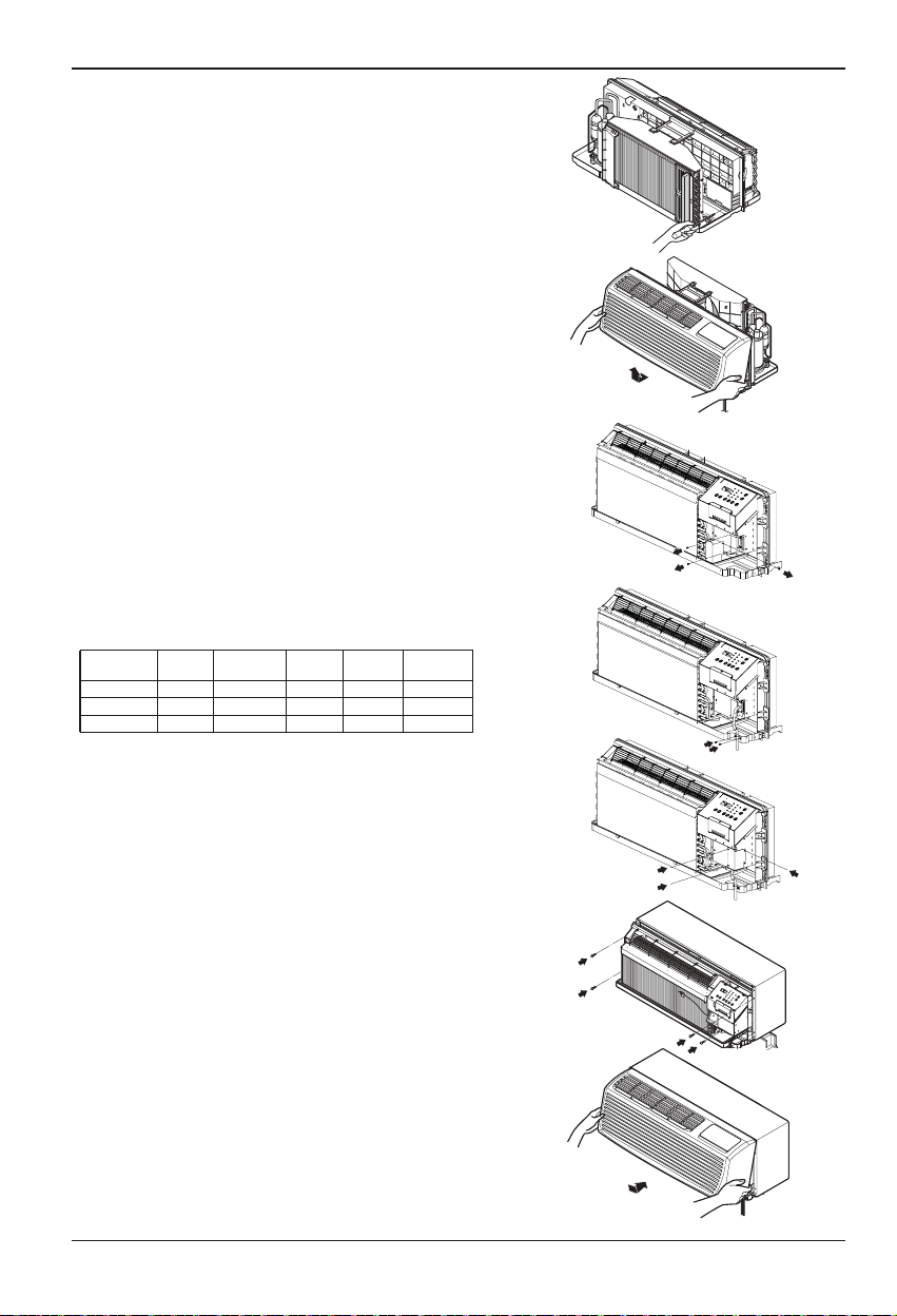
• UNIT INSTALLATION
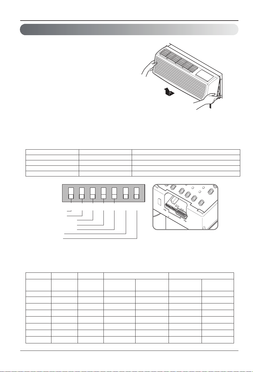
1. Remove the shipping screw from the ventilation door.
2. Remove the front gille by pulling it out at the bottom
to release it, then lift it up along the unit top front.
3. Remove cover by removing 3 screws from front.
4. Connect accessory power supply cord, and fix power
cord to basepan with screws.
ELECTRIC HEATER RATING
(CONFIGURATION BASED ON POWER CORD)
POWER CORD
AYUH2115 2 400/2 300 W
AYUH2120
AYUH2130
VOLTAGE
230/208
230/208
230/208
HEATER
WATTS
3 300/3 200 W
HEATER MAX.
CURRENT
FUSE SIZE
10.5/11.2 A
14.5/15.5 A
20.6/22.3 A
15 A
20 A
30 A4 700/4 600 W
MIN.CIRCUIT
AMPACITY
14.5 A
19.8 A
28.3 A
5. Replace cover with screws. Tighten securely.
6. Slide the unit into the wall sleeve and secure with
4 screws through the unit flange holes.
7. Reinstall the front grille by hooking the top over the
unit top, then pushing it in at the bottom.
12 Room Air Conditioner
Page 13

Control Locations
INDOOR
IN
D
OO
R
Control Locations
Manual Controls
• VENTILATION
The ventilation lever is located to the lower left side
of the unit.
The ventilation lever must be in the CLOSE position in
order to maintain the best cooling & heating conditions.
When fresh air is necessary in the room, set the
ventilation lever to the OPEN position.
The Ventilation door is opened and outdoor air is
drawn into the room.
This will reduce the cooling or heating efficiency.
When the air conditioner has been running and is
turned off or set to the fan position, wait at least 3
minutes before resetting to the cooling & heating
operations.
Note:
A slight heat odor may come from the unit
when first switching to HEAT after the
cooling season is over.
This odor, caused by fine dust particles on
the heater, will disappear quickly.
This is harmless.
VENT
VENT
CLOSE
OPEN
Ventilation door
ENGLISH
• Failure to follow this caution may result in equipment
damage or improper operation.
• Blocking indoor(curtain or bedclothes etc.) or outdoor
discharge air could cause premature failure of unit.
If there has a gap between rear side of product &
•
outside wall, the air splitter need to be used on
unit.
Rear side of product
Air Splitter
Outside Wall
Ownerʼs Manual 13
Sleeve
Wall
Page 14

Control Locations
Electronic Controls
FAN SPEED
• Every time you push this button, it cycles through the settings as follows:
{High(F2)
MODE
-
Push this button to cycle through the modes from
COOL
- COOL
• Fan runs continually for normal cooling operation.
- ENERGY SAVER
• The fan stops when the compressor stops cooling & heating
operations. Approximately every 3 minutes the fan will turn on and
the unit will check the room air temperature to determine if cooling
& heating is needed.
• For Energy saver operation Dip switch #2 is ON position. Refer
Dipswitch setting at P.No 16
- FAN
• Fan operation without heating or cooling.
- HEAT
• Fan runs continually for normal heating operation.
Low(F1) High(F2)}
°F
FAN HEAT COOL.
POWER
• To turn ON the air conditioner, push this button.
To turn OFF the air conditioner, push this button
again.
• This button takes priority over any other button.
TEMPERATURE SETTING
• Use this button to automatically control the
temperature of the room.
The temperature can be set within a range of
54°F (12°C) to 86°F (30°C) by increments of
1°F (0.5°C).
• The setting temperature in the display.
TIMER
- SHUT-OFF TIME
• You will usually use shut-off time while you sleep.
• If unit is running, use Timer to set number of hours until shut-off.
• For your sleeping comfort, once Time is set, the setting temperature will raise 2°F after 30 minutes, and once again
after another 30 minutes.
• Push Timer to cycle through the settings from 1 Hour
14 Room Air Conditioner
2 Hours ... 12 Hours maximum.
Page 15

Control Locations
ENGLISH
Self-Diagnosis
FUNCTION:
If the unit has a malfunction, a green OPERATION LED located on the Display PCB used by the unit to
indicate the fault codes.
USE:
If the customer has to register a complaint to the service center, he can be very clear about registering
the complaint that what is happening & by referring the user's manual the customer can clearly define
the problem.
So that the engineer should go fully prepared with the prescribed tools to be used regarding that
problem. It also keeps the customer aware about the unit.
Here are some of the problems defined below for which the LED indicates by flashing.
The fault codes are the mentioned which is as follows:
• Electrical Controls
ON Normal
OFF No power / failed board
Fault Codes
CH 01
CH 02
CH 07
CH 09
CH 10
CH 34
CH 44
CH 45
CH 67
Indoor Air Thermistor Error
Indoor Coil Thermistor Error
Themostat Wiring Error
EEPROM Check Sum Error
Indoor Fan Error
High Pressure Switch Error
Outdoor Air Thermistor Error (PTHP Only)
Outdoor Coil Thermistor Error (PTHP Only)
Outdoor Fan Error
NOTICE
Function Description Display code
Over heating Protection
Freeze Protection
Remote Mode When use the remote mode operation
This feature prevents melting of unit by electrical heater
located inside of the unit at the remote mode (when the
unit is connected with wall thermostat).
This feature prevents freezing of room at low
temperature.
°F
°F
°F
Owner’s Manual 15
Page 16
Control Locations
Additional Controls
• REMOVING THE FRONT GRILLE
Additional controls are available after
removing the front grille and option
cover of control box.
To remove the front grille, pull out the
bottom of front grille and then lift up.
To reinstall the front grille, place the tabs
over the top of the unit and push the
bottom of front grille until the clips snap
into place.
• ADDITIONAL CONTROLS
The additional controls are located behind the option cover of control box. The standard settings will be in
the OFF position. The authorized service engineer has to check switches and ensure the switches are in
the desired position.
Dip switch setting is done at factory according to product specification.
#6 #7 Unit Type
OFF OFF Cooling+Electric Heater+Heat Pump
OFF ON Cooling+Electric Heater
ON OFF Heat Pump Only
ON ON Cooling Only
ONREMOTE
ON
ON ON ON
OFF
LOCAL
LOCAL
LOCAL
LOCAL
LOCAL
LOCAL
OFF2OFF3OFF4OFF5OFF6OFF
OFF2OFF3OFF4OFF
OFF2OFF3OFF4OFF
OFF2OFF3OFF4OFF
OFF2OFF3OFF4OFF
OFF2OFF3OFF4OFF
1
1
1
1
1
Remote/Local
Energy Saver
Temperature Limit 1
Temperature Limit 2
Temperature Limit 3
PTAC/PTHP
UNIT TYPE
1
5
5
5
5
5
7
• TEMPERATURE LIMITING
Temperature Limiting can save money by limiting the lowest temperature for cooling and the highest temperature for heating.
The temperature limiting is controlled by switches #3 - #5.
This temperature limiting is not available with the Remote Wall Thermostat.
Cooling Operation noitarepO gnitaeH5#4#3#
Temperature Temperature Temperature
Limit #1 Limit #2 Limit #3
OFF OFF OFF 54 F (12.2 C) 86 F (30.0 C)
ON OFF OFF 56 F (13.3 C) 84 F (28.9 C)
OFF ON OFF 58 F (14.4 C) 82 F (27.8 C)
ON ON OFF 60 F (15.5 C) 80 F (26.7 C)
OFF )C 5.52( F 87)C 6.61( F 26NOFFO
ON OFF ON 64 F (17.7 C) 76 F (24.4 C)
OFF ON ON 66 F (18.9 C) 74 F (23.3 C)
ON ON ON 68 F (20.0 C) 72 F (22.2 C)
Lowest Temp. Highest Temp. Lowest Temp. Highest Temp.
86 F (30.0 C)
86 F (30.0 C)
86 F (30.0 C)
86 F (30.0 C)
86 F (30.0 C)
86 F (30.0 C)
86 F (30.0 C)
54 F (12.2 C)
54 F (12.2 C)
54 F (12.2 C)
54 F (12.2 C)
54 F (12.2 C)
54 F (12.2 C)
54 F (12.2 C)
54 F (12.2 C)
86 F (30.0 C)
16 Room Air Conditioner
Page 17

Control Locations
• REMOTE/LOCAL CONTROL
When remote/local switch #1 is on, it allow the unit to operate by the Remote Wall Thermostat.
The unit control by buttons are not available.
• ENERGY SAVER
The energy saver switch #2 is on. This switch is set at cycle fan to provide continuous fan operation in cool
or heat modes. When the switch is off the continuous fan allows continuous circulation of room air and
make the more balanced temperature of the room. When the switch is on, the fan is on or off with the
compressor or with the heater.
• FRONT DESK CONTROL
When the pair wire is connected to the connector FD2 and FD1, the unit can be turned ON or OFF with a
switch located at the Front Desk Control panel. When the front desk switch is ON, the fan operates
according to the setting without working compressor and heater. When the front desk switch is OFF, the unit
can operate according to the setting of controls.
Wire # AWG Maximum Length
#22 600 ft (180 m)
#20 900 ft (270 m)
#18 1500 ft (450 m)
#16 2000 ft (610 m)
Front Desk Control
Front Desk Control
FD2 FD1 DR2 DR1 MS2 MS1
ENGLISH
(Molex Housing Spec 396-06V)
• REMOTE WALL THERMOSTAT
When the wires are connected, the unit will be controlled
by a remote wall thermostat.
The thermostat connections supply the 24 Volt AC. When
you install the digital/electronic thermostat, you
to 24 Volt AC.
24 Volt-N
24 Volt-L
Compressor
Heater
Reversing Valve
High Fan
Low Fan
GL GH O W Y R C
(Molex Housing Spec 396-07V)
NOTICE
For wiring connection of Wall Thermostat, check the Installation instruction or Installation manual’s
provided by Thermostat Company.
must set it
Room Air Conditioner 17
Page 18
Control Locations
INDOOR
INDOOR
40˚
15˚
INDOOR
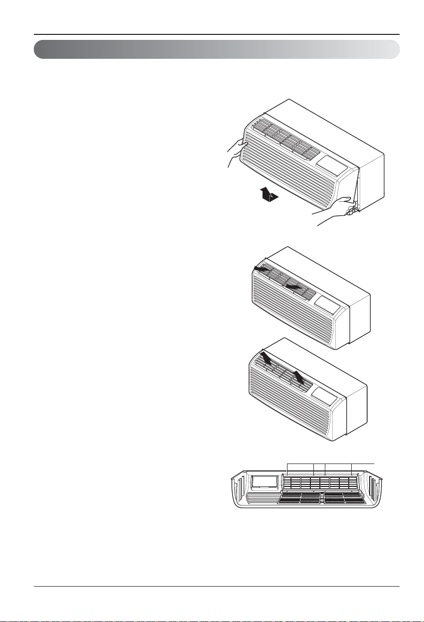
Disassembly Instructions
- Before the following disassembly, POWER SWITCH is set to OFF and disconnected the power
cord.
1. Remove the front grille.
2. To remove the front grille, pull out the bottom
of the front grille and then lift up.
Re-install the component by referring to the
removal procedure.
3. To reinstall the front grille, place the tabs over
the top of the unit and push the bottom of front
grille until the clips snap into place.
• This Room Air Conditioner (PTAC) discharges
air from the top of the unit through reversible, 2position discharge grille louvers. The unit is
shipped from the factory with the discharge grille
louvers at an angle of 40” off vertical. In an
alternate position the louvers will be at an angle
of 15” off vertical.
To adjust the air direction, remove the front
grille. Remove the 4 screws that fasten the
discharge grille to the front grille.
Rotate the discharge grille 180°, then assembly the
discharge grille to the front grille with 4 screws.
18 Room Air Conditioner
Screws
Page 19

Maintenance and Service
ENGLISH
Maintenance and Service
TURN OFF THE AIR CONDITIONER AND REMOVE THE PLUG FROM THE POWER OUTLET.
Air Filter Cleaning
The air filter should be checked at least twice a month to see if cleaning is necessary.
Trapped particles in the filter will build up and block the airflow. This reduces the cooling
capacity and also causes an accumulation of frost on the cooling coils.
If the filter becomes turn or damaged you should replace
immediately. Replacement filters are available from your
salesperson, dealer, and the authorized customer service
centers.
1. Remove the air filter from the front grille assembly by
pulling the air filter up slightly.
2. Wash the filter using lukewarm water below 104° F(40°C).
3. Gently shake the excess water from the filter completely.
Reinstall the filter.
INDOOR
Vent Filter
Before cleaning the vent filter, disconnect power to the
unit by unplugging the power cord at the wall outlet or
subbase, or disconnect power at the fuse box or circuit
breaker. If unit is operated with vent door closed, the
vent filter does not need to be cleaned.
1. Remove the front grille as described in front grille
Removal.
2. Remove the 4 screws securing the chassis to the
wall sleeve with a Phillips-Head screwdriver.
3. Slide the chassis out of the wall sleeve far enough so
that the vent filter is accessible as shown in Figure A.
4. Remove the vent filter by unscrewing the two screws
at the top of the filter and gently pulling the filter away
from the partition panel. Refer to Figure B.
5. Clean and reinstall the filter by reattaching the hook
to the bottom of the vent door and replacing the two
screws, slide the chassis back into the wall sleeve,
secure it in place with 4 screws and reinstall the
front cabinet.
Figure A – Vent (Left side of unit)
Figure B – Vent Filter Removal
Ownerʼs Manual 19
Page 20

Maintenance and Service
Drain Cap
Drainage
The base pan may overflow due to high humidity.
To drain the excess water, remove the drain cap
from the back of the unit.
Chassis
The chassis must be cleaned every four months or more often as the atmospheric conditions
require. Use water and detergent to clean the basepan, center partition and coils. The use of harsh
cleaning materials may cause a deterioration of the coil fins or endplates. Do not use a high
pressure cleaner as it could cause severe damage to the PTAC fins and coils. A hose is okay to use
to clean the coils, but make sure to cover the control with a blanket or plastic bag to keep it dry.
Compressor / Fan Motor
The compressor and fan motor are hermetically sealed, permanently lubricated, and require no
additional oiling.
Front Grille
The Front Grille and discharge air grille can be cleaned with a mild soap or detergent. Under no
circumstances should hydrocarbon based cleaners (e.g. acetone, benzene, naphtha, gasoline, etc.)
be used to clean the front or air grilles.
Use care when cleaning the control area. Do not use an excessively wet cleaning cloth.
20 Room Air Conditioner
Page 21

Maintenance and Service
unplugged.
completely into the outlet.
ENGLISH
Common Problems and Solutions
Troubleshooting Tips save time and money!
Review the chart below first and you may not need to call for service.
Normal Operation
• You may hear a pinging noise caused by water being picked up and thrown by the slinger fan against the
condenser on rainy days or when the humidity is high. This design feature helps remove moisture and
improve efficiency.
• You may hear the thermostat click when the compressor cycles on and off.
• Water will collect in the base pan during high humidity or on rainy days. The water may overflow and drip
from the outdoor side of the unit.
• The fan may run even when the compressor does not.
Troubleshooting
Problem Possible Causes What To Do
Air conditioner
does not start
Air conditioner
does not
cool/Heat
as it should
The air conditioner is
The fuse is blown/circuit
breaker is tripped.
Power failure. If power failure occurs, turn the mode control
The current interrupter
device is tripped.
Airflow is restricted. Make sure there are no curtains, blinds, or
The temp control may not
be set correctly.
The air filter is dirty. Clean the filter at least every 2 weeks.
The room may have been hot. When the air conditioner is first turned on,you
The room may have been cold. When the air conditioner is first turned on,you
d air is escaping. Check for open furnace floor registers and
Col
Hot air is escaping.
Cooling coil have iced up. See Air Conditioner Freezing Up below.
Make sure the air conditioner plug is pushed
Check the house fuse/circuit breaker box and
replace the fuse or reset the breaker.
to Off. When power is restored, wait 3
minutes to restart the air conditioner to
prevent tripping of the compressor overload.
Press the RESET button located on the power
cord plug. If the RESET button will not stay
engaged, discontinue use of the air conditioner
and contact a qualified service technician.
furniture blocking the front of the air
conditioner.
In COOL mode, press the " - " pad.
In HEAT mode, press the " + " pad.
See the care and Maintenance section.
need to allow time for the room to cool down.
need to allow time for the room to heat up.
cold air returns.
Make sure that all vents are closed to air returns.
Air conditioner
freezing up
The cooling coils are iced
over.
Ice may block the air flow and obstruct the air
conditioner from properly cooling the room.
Set the mode control at High Fan or High
Cool.
Ownerʼs Manual 21
Page 22

Maintenance and Service
Problem Possible Causes What To Do
Water drips
outside
Water drips
indoors
Water collects
in base pan
Air conditioner
turns on and
off rapidly.
Noise when
unit is
cooling/Heating
Room too
cold/heat.
Hot, humid weather. This is normal.
The air conditioner is not
tilted to the outside.
Moisture removed from air
and drains into base pan.
Dirty air fi
Outside temperature
extremely hot.
Air movement sound.
Poor installation. Refer to installation instructions or check with
Set temperature too low Increase set temperature
Set temperature too high Decrease set temperature
lter - air restricted. Clean air filter.
For proper water disposal, make sure the air
conditioner slants slightly from the case front
to the rear.
This is normal for a short period in areas with
little humidity; normal for a longer period in
very humid areas.
Set FAN speed to a faster setting to bring air
through cooling coils more frequently.
This is normal. If too loud, set to lower FAN setting.
installer.
22 Room Air Conditioner
Page 23

Maintenance and Service
ENGLISH
Ownerʼs Manual 23
Page 24

PARA SUS ARCHIVOS
Escriba aquí el modelo y número de serie:
Modelo n°:
Manual del usuario del acondicionador de aire tipo Ventana
TABLA DE CONTENIDOS
Precauciones de Seguridad .........25
Antes de poner el equipo en
funcionamiento..............................29
Introducción...................................30
Seguraida Electrica.......................31
Serie n°:
Puede encontrarlos en la etiqueta de calidad y el panel frontal
de la base de cada unidad.
Nombre del distribuidor:
Fecha de compra:
Adjunte su recibo a esta página con la grapadora para el
momento que lo necesite para probar la fecha de su
adquisición o para la validación de la garantía.
Instalacion......................................33
Ubicación de los controles...........35
Mantenimiento y asistencia
técnica............................................41
LEA ESTE MANUAL
En su interior encontrará muchos consejos útiles sobre la
utilización y mantenimiento de su acondicionador de aire.
Unos pocos cuidados por su parte le pueden ahorrar
mu cho tiem po y d ine ro dur ante l a v ida de su
acondicionador de aire.
En la tab la de con sej os para la sol ución rápid a de
problemas encontrará muchas respuestas a los problemas
más habituales. Si revisa primero nuestra Tab la de
Consejos para la solución rápida de problemas, tal vez no
necesite llamar nunca al servicio técnico.
PRECAUCIÓN
• Póngase en contacto con un técnico del servicio
autorizado para realizar la reparación y
mantenimiento de esta unidad.
• Póngase en contacto con un instalador para realizar
la instalación de esta unidad.
• Cuando se va a cambiar el cable eléctrico, el trabajo
de reemplazamiento debe ser realizado únicamente
por personal autorizado, utilizando las piezas de
cambio genuinas únicamente.
• El trabajo de reemplazamiento debe ser realizado de
acuerdo con el Código Eléctrico Nacional únicamente
por personal autorizado.
24 Aparato de aire acondicionado
Page 25

ESPAÑOL
Precauciones de Seguridad
Precauciones de Seguridad
ADVERTENCIA
ADVERTENCIA
n Instalación
No hacer.
Siga estas instrucciones.
No utilice un cable de
alimentación, enchufe o una
toma suelta que esté dañada.
• De lo contrario, podría provocar
un incendio o descarga
eléctrica.
Enchufe siempre a un
tomacorriente que tenga
toma a tierra.
• De lo contrario, podría provocar
un incendio o descarga
eléctrica.
No modifique ni alargue el
cable de alimentación.
• De lo contrario, puede provocar
una descarga eléctrica o
incendio debido a la generación
de calor.
No desmonte ni modifique
los productos.
• Puede ocasionar fallos y una
descarga eléctrica.
Tenga cuidado al
desembalar e instalar el
aparato.
• Los bordes afilados pueden
provocar lesiones.
No use el cable de alimentación
cerca gas inflamable o
materiales combustibles tales
como la gasolina, benceno,
disolvente, etc.
• Podría ocurrir una explosión o
incendio.
Se deben seguir las siguientes instrucciones, para evitar lesiones al usuario y daños a la propiedad.
Una operación incorrecta por ignorar las instrucciones provocará lesiones o daños. La seriedad se clasifica
por las siguientes indicaciones.
Este símbolo indica la posibilidad de muerte o de seria lesión.
PRECAUCION
Meanings of symbols used in this manual are as shown below.
Este símbolo indica sólo la posibilidad de lesiones o daños a la propiedad
Gasolin
Manual del propietario 25
Page 26

Precauciones de Seguridad
n Operación
No ponga el cable de
alimentación cerca de un
calentador.
• Puede ocasionar un incendio y
una descarga eléctrica.
No permita que entre agua
en las piezas eléctricas.
• Puede provocar fallos en el
producto o descargas
eléctricas.
Utilice un paño suave para
limpiar. No utilice cera,
disolventes o detergentes fuertes.
•
La apariencia del aparato de aire
acondicionado puede deteriorar,
cambiar el color o desarrollar flujos en
las superficies.
Ventile bien la sala al usar
este aparato con una estufa,
etc.
• Puede ocurrir un falta de
oxígeno.
Apague el aparato y el
interruptor diferencial
primero antes de limpiar la
unidad.
•
Debido a que el ventilador gira a
alta velocidad durante el
funcionamiento, podría ocasionar
lesiones.
Apague el interruptor de
alimentación principal cuando
no vaya a utilizar el aparato
durante mucho tiempo.
• Evitará el arranque accidental y
la posibilidad de lesiones.
Desenchufe la unidad si oye
un sonido extraño, olores, o
si observa salir humo.
• De lo contrario, puede ocurrir
un incendio y un accidente por
descarga eléctrica.
No abra la parrilla de
entrada al aparato mientras
está en funcionamiento.
• De lo contrario, pueden ocurrir
descargas eléctricas y fallos.
Si entra agua en el producto,
apague el interruptor de la carcasa
principal del aparato. Póngase en
contacto con el centro de servicio
después de haber sacado el
enchufe del tomacorriente.
No use el cable de alimentación
cerca gas inflamable o materiales
combustibles tales como la
gasolina, benceno, disolvente, etc.
• Puede ocasionar una explosión
o descarga eléctrica.
No comparta el
tomacorriente con otros
electrodomésticos.
•
De lo contrario, puede provocar una
descarga eléctrica o incendio debido
a la generación de calor.
Saque el enchufe en caso de
necesidad, sosteniendo la
cabeza del enchufe y no lo
toque con las manos mojadas.
•
De lo contrario, podría provocar un
incendio o descarga eléctrica.
Thinner
Wax
26 Aparato de aire acondicionado
Page 27

ESPAÑOL
Precauciones de Seguridad
PRECAUCION
n Instalación
No opere ni detenga la
unidad insertando o
estirando de enchufe.
• De lo contrario, puede provocar
una descarga eléctrica o
incendio debido a la generación
de calor.
No dañe ni use un enchufe
de alimentación no
especificado.
• Provocará descargas eléctricas
o incendios.
No toque el producto con
las manos mojadas o en un
ambiente húmedo.
• Provocará descargas eléctricas.
Sostenga el enchufe por su
cabeza al sacarlo.
• Podría ocasionar una descarga
eléctrica y daños.
Cuando haya un escape de
gas, abra la ventana para
ventilar antes de poner en
marcha la unidad.
• De lo contrario, podría ocurrir
una explosión o incendio.
No toque las partes
metálicas del aparato al
sacar el filtro del aire.
• Son puntiagudas y pueden
provocar lesiones.
Instale el producto de modo que el ruido o
el aire caliente producido por la unidad
externa no moleste a los vecinos.
• De lo contrario puede dar lugar a disputas
vecinales.
Mantenga nivelado el producto al instalarlo.
• De lo contrario se podría causar vibraciones o
escapes de agua.
Para una limpieza interna, contacte con un centro de servicios autorizado o un revendedor.
No utilice detergentes abrasivos que puedan corroer o dañar la unidad.
• Los detergentes abrasivos pueden igualmente generar un fallo del producto, incendio, o descarga.
Manual del propietario 27
Page 28

Precauciones de Seguridad
n Operación
Tenga cuidado para no tocar los
bordes puntiagudos al instalar.
• Podría ocasionar lesiones.
Evite un enfriamiento excesivo y
ventile en ocasiones.
• De lo contrario, podría dañar su salud.
No introduzca la mano ni barras en
la entrada o salida del aire durante
el funcionamiento del aparato.
• De lo contrario, podrían ocurrir lesiones
personales.
Si entra líquido de las pilas en contacto con la piel o
ropa, lávela inmediatamente con agua. No utilice el
mando a distancia si las pilas tienen fugas.
• Los productos químicos de las pilas podrían causar
quemaduras u otros perjuicios a la salud.
Si el líquido de las pilas alcanzara su boca, cepille sus
dientes y consulte a un médico.No utilice el mando a
distancia si las pilas han experimentado fugas.
• Los productos químicos de las pilas podrían causar
quemaduras u otros perjuicios a la salud.
No ponga plantas ni animales en
la trayectoria que recorrerá el aire
caliente.
• Podría ocasionar lesiones.
No bloquee la entrada ni la salida
del flujo de aire.
• Puede causar una avería en el aparato.
Utilice un paño suave para
limpiar. No utilice cera,
disolventes o detergentes fuertes.
•
La apariencia del aparato de aire
acondicionado puede deteriorar, cambiar el
color o desarrollar flujos en las superficies.
No se suba a la unidad
interior/exterior ni coloque
objetos sobre la misma.
• Puede lesionarse al caerse del aparato o
al caerse los objetos que haya colocado.
Inserte siempre el filtro
correctamente.
Límpielo cada dos semanas.
• El funcionamiento sin filtros puede
provocar fallos.
No beba el agua que drena el
aparato de aire acondicionado.
28 Aparato de aire acondicionado
Page 29

ESPAÑOL
Antes de poner el equipo en funcionamiento
Antes de poner el equipo en funcionamiento
1. Póngase en contacto con un especialista para realizar la instalación.
2. Enchufe correctamente la toma de alimentación.
3. Utilice un circuito dedicado.
4. No utilice un cable alargador.
5. No inicie/cese el funcionamiento enchufando/desenchufando el cable
eléctrico.
6. Si el cable/enchufe está dañado, sustitúyalo solo por una pieza autorizada.
1. Estando expuesto a la circulación directa de aire durante un extenso período
de tiempo podría resultar peligroso para su salud. No exponga a las personas,
animales domésticos, o a las plantas a la circulación de aire durante largos
períodos de tiempo.
2. Debido a la probabilidad de falta de oxígeno, ventile el cuarto cuando esté
utilizado el aparato junto con estufas u otros aparatos de calefacción.
3. No utilice este aire acondicionado con propósitos especiales no especificados
(Ej.: conservación de dispositivos de precisión, comida, animales domésticos,
plantas y objetos de arte). Tal uso podría dañar los artículos.
1. No toque las piezas metálicas de la unidad al retirar el filtro. Manejar aristas
afiladas de metal puede causar lesiones.
2. No utilice el agua para limpiar el interior del aire acondicionado. La exposición
al agua puede destruir el aislamiento, conduciendo a posibles descargas
eléctricas.
3. Al limpiar la unidad, asegúrese antes de que la electricidad y el interruptor
están apagados. El ventilador rota a muy alta velocidad durante el
funcionamiento del equipo. Existe la posibilidad de lesiones si acciona
accidentalmente la electricidad de la unidad mientras limpia el interior de la
unidad.
Para cuestiones de reparación y mantenimiento, póngase en contacto con su
distribuidor de servicio autorizado.
Preparación para el funcionamiento
Uso
Limpieza y mantenimiento
Servicio
Manual del propietario 29
Page 30

Introducción
Este símbolo le avisa del riesgo de descarga eléctrica.
Este símbolo le avisa de los peligros que podrían dañar el
aparato de aire acondicionado.
Este símbolo indica notas especiales.
AVISO
ADVERTENCIA
Introducción
Símbolos utilizados en este manual
Funciones
Este acondicionador de aire se debería instalar de acuerdo con el Código Eléctrico Nacional.
.
La rejilla de metal expandida debería utilizarse para mejorar el rendimiento en los sistemas de aire
acondicionado PTAC y PTHP.
Por motivos de instalación y para mejorar la apariencia, se puede utilizar la rejilla arquitectónica o de
aluminio en las unidades PTAC y PTHP.
DEFLECTOR DE AIRE VERTICAL
(Rejilla de ventilación horizontal)
FILTRO DE AIRE
REJILLA FRONTAL
(Entrada de aire)
30 Aparato de aire acondicionado
EL MANGUITO Y LA REJILLA POSTERIOR
(Disponible opcionalmente)
REJILLA POSTERIOR
MONTAJE DEL MANGUITO
(Rejilla posterior de aluminio)
Arquitectura de la
rejilla posterior
INDOOR
REJILLA METÁLICA EXPANDIDA
Page 31

ESPAÑOL
Seguraida Electrica
Seguraida Electrica
Datos Electricos
No presione nunca el botón de prueba durante
el funcionamiento, de lo contrario el enchufe
podría resultar dañado.
Este dispositivo contiene productos químicos,
incluyendo plomo, conocido en el estado de
California como producto cancerígeno y causante
de defectos de nacimiento y otros daños al sistema
reproductor. Lávese bien las manos tras manipular
el dispositivo. No desmonte, modifique ni sumerja
en agua este enchufe.
Si el dispositivo se activara, deberá corregir la
causa antes de volver a utilizarlo.
Los hilos conductores dentro del cable están
rodeados por blindajes, que supervisan la corriente
de fuga. Estos blindajes no están puestos a tierra.
<Fabricado en Tower>
Examine periódicamente el cable en busca de
cualquier daño. No utilice este producto si los
blindajes resultaran expuestos.
Evite el riesgo de descargas eléctricas; esta unidad
no puede ser reparada por el usuario por ser
resistente y a prueba de alteraciones. Manipular la
porción sellada de la unidad anulará todas las
garantías y quejas de rendimiento. Esta unidad no
está diseñada para su uso como un interruptor de
encendido-apagado.
PRECAUCION
ADVERTENCIA
La forma puede ser diferente según su modelo.
AVISO
NO USE CABLE DE EXTENSIÓN EN UNIDADES DE
208, 230, AND 208/230, 265 VOLTIOS.
Todo el cableado deberá realizarse de acuerdo con
los códigos y reglamentos eléctricos locales.
El cableado doméstico de aluminio podría
ocasionar problemas especiales. Consulte a un
electricista calificado.
AVISO
208/230V~ 265V~
El cable de alimentación puede incluir un dispositivo
interruptor de corriente. La carcasa del enchufe cuenta con
un botón de prueba y otro de reinicio. El dispositivo debe
comprobarse periódicamente presionando primero el botón
TEST y después RESET.
Si el botón TEST no se desconecta o si el botón RESET no
permanece activo, suspenda el uso del aire acondicionado
y póngase en contacto con un técnico de servicio
cualificado.
* En el caso de un cable de energía de 265 v, no hay un
dispositivo interruptor de corriente.
Utilice el enchufe de la pared Consumo de Energía
Utilice un fusible de
15AMP. o un
Standard 208/230V, enchufe de 3
Líneas de 15A
Standard 208/230V, enchufe de 3
Líneas de 20A
Standard 208/230V, enchufe de 3
Líneas de 30A
Standard 265V
Líneas de 20A
Standard 265V
Líneas de 30A
Interruptor de 15AMP.
Utilice un fusible de
20AMP. o un
Interruptor de 20AMP.
(2500W Calentadora ơ
o un Interruptor de 15AMP.)
Utilice un fusible de
30AMP. o un
Interruptor de 30AMP.
Utilice un fusible de
20AMP. o un
Interruptor de 20AMP.
Utilice un fusible de
30AMP. o un
Interruptor de 30AMP.
Manual del propietario 31
Page 32

Seguraida Electrica
IMPORTANTE
(FAVORLEA CON ATENCIÓN)
POR LA SEGURIDAD PERSONAL DEL USUARIO,
ESTE APARATO DEBE SER DEBÍDAMENTE
NEUTRALIZADO.
El cordón de energía de éste aparato esta equipado
con tres patas(cable a tierra). Utilice éste con un
enchufe de pared de tres salidas(a tierra) para
minimizar el peligro de choque eléctrico. El cliente
debe revisar el receptor de pared y el circuito por un
electricista calificado para asegurarse que la
recepción esta debidamente neutralizada.
NO CORTE O REMUEVA LA TERCERA
PATA(GROUND) DEL ENCHUFE.
A. SITUACIONES EN LAS CUALES EL APARATO
ES DESCONECTADO
OCASIONALMENTE:
Debido al peligro potencial, nosotros no
recomendamos el uso de adaptadores. Sin
embargo, si usted desea utilizar un adaptador, una
CONEXIÓN TEMPORAL, puede ser
efectuada. Utilice adaptadores UL, disponibles en la
mayoría de los estable cimientos de
herramientas. La pata mas grande del adaptador
debe ser alineada con la pata mas grande del
interruptor para asegurarse una polarización
adecuada.
Adaptar la terminal del ground del adaptador a
la cubierta de la pared con un
tornillo no neutraliza el aparato a menos que la
cubierta del tornillo sea de metal, u no sea
insolada, y el receptor de pared este
neutralizado a través del alambrado del la casa.
El cliente debe hacer verificar el circuito por un
electricista calificado para asegurarse que el
receptor esta debidamente neutralizado.
Desconecte el cordón de energía del adaptador,
utilizado una mano en cada uno. De lo contrario, la
terminal del adaptador puede romperse. NO UTILICE el
aparato con un enchufe roto.
B. SITUACIONES EN LAS CUALES EL APARATO
ES DESCONECTADO CON
FRECUENCIA.
No utilice un adaptador en estas circunstancias.
Desconectar el cordón de energía con frecuencia lo
llevará al eventual rompimiento de la terminal de
neutralización. La saluda de energía de la pared
debe ser reemplazada por una salida de tres
patas(neutralizada).
USO DE EXTENSIONES
Debido al peligro potencial, no recomendamos la
utilización de extensiones. Sin embargo, si usted
desea utilizar una extensión, utilice una
certificada por CSA/UL de tres alambres,
catalogada 15A, 125V.
PRECAUCION
Seguraida Electrica
32 Aparato de aire acondicionado
Page 33

Cómo instalar la unidad
Instalación
PRECAUCION
Instalación
Dimensiones del aparato de aire acondicionado
• Necesita dos personas para levantar el acondicionador
de aire, es PESADO.
Mida las dimensiones de la pared para el manguito existente.
Para obtener el mejor rendimiento, instale el nuevo aparato de
aire acondicionado de acuerdo con estas instrucciones de
instalación. Todos los manguitos de pared utilizados para el
montaje del nuevo aparato de aire acondicionado deben estar en
un estado estructural adecuado y disponer de la rejilla posterior
que se fija de forma segura al manguito o a la abrazadera del
manguito para sujetar el nuevo aparato de aire acondicionado.
Dimensiones del montaje del manguito (opcional)
• Para evitar vibraciones y ruido, asegúrese de que la unidad está
instalada de forma segura y firme.
Al instalar la caja y la rejilla frontal, asegúrese de que no hay
nada a menos de 21”, ya sea por delante o por detrás, de
ambos que pudiera interferir con la radiación de calor y los aires
de escape.
PRECAUCION
• Antes de la instalación, compruebe el aislamiento en el lado
interior del manguito. Si no hay aislamiento, proceda a añadirlo.
• Compruebe el espacio de unión en la esquina inferior del
manguito. En caso de existir dicha separación, rellénela con
masilla.
AVISO
PPara mantener el mejor rendimiento
de LG PTAC
1. Se debe adjuntar una cinta de aislamiento.
La cinta de aislamiento se suministra con la
caja.
2. Después de ensamblar la manga y la rejilla
frontal, la separación debería ser mayor de
Espacio de unión
AISLAMIENTO
AIRE
REFRIGERADO
ENTRADA
DE AIRE
Burbuja del
nivel de 1/4"
Más de 20"
20" desde ambos. Para ensamblar el modelo
PTAC consulte el diagrama
1) Extraiga la banda de aislamiento del embalaje superior.
2) Fije la banda de aislamiento sobre el lado superior de la parte
posterior del manguito de pared.
280 mm
(11")
1,066 mm
(42")
INDOOR
1066 mm
(42")
Aislamiento
PARED
PARED
Parte frontal
ALOJAMIENTO
406 mm
(16")
349 mm
3
(13
/4")
536 mm
(21")
406 mm
(16")
349 mm
3
/4")
(13
ALOJAMIENTO
RADIACIÓN
DE CALOR
Más de 20"
Banda aislante
ESPAÑOL
Posterior
Manual del propietario 33
Page 34

Instalación
• INSTALACIÓN DE LA UNIDAD
1. Quite el tornillo de embalaje de la puerta de
ventilación.
2. Para ello, quite la rejilla delantera tirando de ella
hacia fuera desde la parte inferior y, a continuación,
levántela por encima de la parte delantera de la
unidad.
3. Retire la tapa quitando los 3 tornillos del frente.
4. Conecte el cable de alimentación accesorio y
fíjelo a la bandeja base con tornillos.
POTENCIA NOMINAL DEL CALENTADOR ELÉCTRICO
(CONFIGURACIÓN BASADA EN EL CABLE DE ALIMENTACIÓN)
CABLE DE
ALIMENTACIÓN N.°
AYUH2115 2 400/2 300 W
AYUH2120
AYUH2130
5. Vuelva a colocar la tapa con los tornillos y ajústelos
bien.
VOLTAJE
230/208
230/208
230/208
Vatios del
calentador
3 300/3 200 W
Corriente del
calentador
10.5/11.2 A
14.5/15.5 A
20.6/22.3 A
TAMAÑO MÁX.
AMPACIDAD MÍN.
DE FUSIBLE
15 A
20 A
30 A4 700/4 600 W
DE CIRCUITO
14.5 A
19.8 A
28.3 A
6. Deslice la unidad hacia el interior del manguito de
pared y fíjela con 4 tornillos que deberá introducir por
los orificios de la abrazadera de la unidad.
7. Vuelva a instalar la rejilla delantera enganchando la
parte superior sobre la parte superior de la unidad y,
a continuación, presione en la parte inferior.
34 Aparato de aire acondicionado
Page 35

Ubicación de los controles
PRECAUCION
PRECAUCION
Controles manuales
• VENTILACIÓN
La palanca de ventilación está ubicada en el lateral
izquierdo inferior de la unidad.
La palanca de ventilación debe estar en la posición
CERRADO para mantener las mejores condiciones
de enfriamiento y calefacción..Si necesita aire fresco
en la sala, ajuste la palanca de ventilación en la
posición OPEN. La puerta de ventilación está abierta
y el aire externo fluye dentro de la habitación..
Si el acondicionador de aire ha estado funcionando
y se apaga o se configura en la posición de ventilador,
espere al menos 3 minutos antes de reiniciar las
operaciones de enfriamiento o calefacción.
Nota:
Es posible que note un ligero olor a
calefacción desde la unidad la primera vez
que lo ajuste en HEAT después de la
estación estival.
<None>Este olor, debido a la existencia de
finas partículas de polvo en la calefacción,
desaparecerá rápidamente. Esto es
inofensivo.
Ubicación de los controles
VENTILADOR
VENTILADOR
CERRADO
VENTILADOR
VENTILADOR
ABIERTO
ABIERTO
CERRADO
puerta de ventilación
ESPAÑOL
• El fallo al seguir esta precaución puede causar
daños en el equipamiento o un funcionamiento
incorrecto.
• El bloqueo de la descarga de aire interna (cortina
o ropa de cama, etc.) o externa, puede causar un
fallo prematuro de la unidad.
• Si hay un espacio entre el lado posterior del producto
y la pared externa, se necesita usar el divisor de aire
en la unidad.
el lado posterior del producto
R
OO
D
IN
Separador de aire
la pared externa
Manual del propietario 35
INDOOR
Alojamiento
Pared
Page 36

Ubicación de los controles
Controles electrónicos
FAN SPEED
• Cada vez que pulse este botón, se desplazará por los ajustes de la siguiente forma:
{High(F2)
Low(F1) High(F2)}
°F
POWER
• Para ENCENDER el acondicionador de aire
presione este botón.
Para APAGAR el acondicionador de aire
presione de nuevo este botón.
• La temperatura de configuración aparece en
la pantalla.
MODE
- Pulse este botón para desplazarse por los modos
-
FAN HEAT COOL.
COOL
- COOL
• El ventilador funciona de forma continua para la
operación de refrigeración normal.
- ENERGY SAVER
• El ventilador se para cuando el compresor detiene
las operaciones de enfriamiento y calefacción.
Aproximadamente cada 3 minutos el ventilador se
encenderá y la unidad revisará la temperatura del
aire para determinar el enfriamiento y calefacción
requerido.
Para una operación con ahorro de energía, el
interruptor tipo DIP #2 está en posición ENCENDIDO.
Consulte la configuración del interruptor DIP en la pág. No. 16.
- FAN
• Funcionamiento del ventilador sin calefacción ni
refrigeración.
- HEAT
• El ventilador funciona de forma continua para la
operación de calefacción normal.
AJUSTE DE LA TEMPERATURA
• Pulse este botón para controlar
automáticamente la temperatura de la sala.
Puede ajustar la temperatura entre 54°F(12°C) y
86°F(30°C) en incrementos de 1°F(0.5℃).
• Este ajuste aparece en la pantalla.
TIMER
- SHUT-OFF TIME
• Normalmente, se utiliza por la noche mientras se duerme.
• Con la unidad en funcionamiento, utilice el temporizador para ajustar las horas durante las que
desea que esté en activada.
• Para dormir con comodidad, y una vez que el temporizador esté ajustado, el ajuste de la
temperatura aumentará en
• Pulse el botón Timer para desplazarse por los ajustes 1 Hour ~ 2 Hours ~ ... ~ 12 Hours maximum.
36 Aparato de aire acondicionado
2°F(1°C)
transcurridos 30 min., y en otros
2°F(1°C)
transcurridos otros 30 min.
Page 37

Ubicación de los controles
ESPAÑOL
Autodiagnóstico
FUNCIÓN:
Si la unidad sufriera una avería, el LED OPERATIVO verde situado en la pantalla PCB utilizado por la
unidad se iluminará para indicar los códigos de error.
USO:
Si el cliente ha registrado una queja en el Centro de servicio, deberá ser muy claro a la hora de registrar
dicha queja, y explicar con nitidez qué está ocurriendo, así como consultar el manual del usuario a fin
de que, como cliente informado, pueda describir el problema.
Esto también ayudará a que el ingeniero pueda acudir en su ayuda con las herramientas necesarias
para su problema. También ayudará a mantener al cliente siempre al tanto de las necesidades y
características de la unidad.
Aquí se muestran algunos de los problemas abajo definidos que el LED indica parpadeando.
Estos códigos de error son los mencionados en la Tabla 13, como se muestra a continuación:
• Controles eléctricos
ENCENDIDO Normal
APAGADO Sin alimentación / error en el panel
Códigos de error
CH01 Error en el termistor de aire interior
CH02 Error en el termistor del serpentín interior
CH07 Error en el cableado del termostato
CH09 Error en la comprobación de suma EEPROM
CH10 Error en el ventilador interior
CH34 Error en el interruptor de alta presión
CH44 Error en el termistor de aire exterior (solo PTHP)
CH45 Error en el termistor del serpentín exterior (solo PTHP)
CH67 Error en el ventilador exterior
AVISO
Función Descripción Código de pantalla
Esta característica impide que la unidad se funda
Protección
anti-sobrecalentamiento
Protección
anti-congelación
Modo remoto Cuando usa el modo remoto
gracias a un calentador eléctrico ubicado dentro
de la misma en modo remoto (cuando la unidad
está conectada mediante termostato).
Esta característica impide que la habitación se
congele a bajas temperaturas.
Manual del propietario 37
°F
°F
°F
Page 38

Ubicación de los controles
Controles adicionales
• EXTRACCIÓN DE LA REJILLA DELANTERA
Los controles adicionales están disponibles al extraer la
rejilla delantera y la tapa opcional de la caja de controles.
Para extraer la rejilla delantera, tire de la parte inferior de
la misma y después hacia arriba.
Para cambiar la rejilla delantera, coloque las lengüetas
sobre la parte superior de la unidad y presione la parte
inferior de la rejilla delantera hasta que las abrazaderas
queden encajadas en su sitio.
• CONTROLES ADICIONALES
Los controles adicionales están ubicados detrás de la tapa opcional de la caja de controles. El ajuste
estándar es la posición OFF.El Ingeniero de servicio autorizado debe revisar los interruptores y
asegurar que estén en la posición deseada.
La configuración del interruptor DIP se hace en fábrica, de acuerdo con la especificación del producto.
Tipo de unidad
ON
ON
ON
#6
ONREMOTO
ON ON ON
#7
OFF
ON
Refrigeración+Calefacción eléctrica+Bomba de calorOFFOFF
Refrigeración+Calefacción eléctricaONOFF
Sólo bomba de calor
Sólo refrigeración
OFF
LOCAL
LOCAL
LOCAL
LOCAL
LOCAL
LOCAL
OFF2OFF3OFF4OFF5OFF6OFF
OFF2OFF3OFF4OFF
OFF2OFF3OFF4OFF
OFF2OFF3OFF4OFF
OFF2OFF3OFF4OFF
OFF2OFF3OFF4OFF
1
1
1
1
1
Remoto/Local
1
5
5
5
5
5
7
Ahorro de energía
Límite de temperatura 1
Límite de temperatura 2
Límite de temperatura 3
PTAC/PTHP
TIPO DE UNIDAD
• LIMITACIÓN DE TEMPERATURA
Puede ahorrar dinero limitando la temperatura al mínimo para la refrigeración y al máximo para la
calefacción. La limitación de la temperatura se controla con los interruptores #3 - #5. Esta limitación de
temperatura no está disponible en el termostato remoto de pared.
#3 #4 #5
Límite de
temperatura 1
OFF OFF OFF 54°F (12.2°C)
ON OFF OFF 56°F (13.3°C) 84°F (28.9°C)
OFF ON OFF 58°F (14.4°C) 82°F (27.8°C)
ON ON OFF 60°F (15.5°C) 80°F (26.7°C)
OFF
ON OFF ON 64°F (17.7°C) 76°F (24.4°C)
OFF ON ON 66°F (18.9°C) 74°F (23.3°C)
ON ON ON 68°F (20.0°C) 72°F (22.2°C)
Límite de
temperatura 2
OFF
Límite de
temperatura 3
ON 62
38 Aparato de aire acondicionado
Funcionamiento de la refrigeración Funcionamiento de la calefacción
Temperatura más baja Temperatura más alta Temperatura más baja Temperatura más alta
°F (16.6°C)
86°F (30.0°C)
86°F (30.0°C)
86°F (30.0°C)
86°F (30.0°C)
86°F (30.0°C)
86°F (30.0°C)
86°F (30.0°C)
86°F (30.0°C)
54°F (12.2°C)
54°F (12.2°C)
54°F (12.2°C)
54°F (12.2°C)
54°F (12.2°C)
54°F (12.2°C)
54°F (12.2°C)
54°F (12.2°C)
86°F (30.0°C)
78°F (25.5°C)
Page 39

Ubicación de los controles
ESPAÑOL
• CONTROL REMOTO/LOCAL
Si el interruptor remoto/local #1 está encendido, la unidad funcionará mediante el termostato remoto de
pared. La unidad controlada por botones no está disponible.
• AHORRO DE ENERGÍA
El interruptor de ahorro de energía #2 está encendido. Este interruptor está ajustado en ventilador de ciclo
para el funcionamiento continuo del ventilador en los modos de refrigeración y calefacción. Si el interruptor
está apagado, el ventilador continuo permite la circulación continua del aire en la sala y un mayor equilibrio
de la temperatura de la misma. Si el interruptor está encendido, el ventilador se activa o se desactiva con el
compresor o con el calefactor.
• CONTROL DEL PANEL FRONTAL
Si el cable par está conectado al conector FD2 y
interruptor ubicado en el panel de control frontal. Si el interruptor del panel frontal está ENCENDIDO, el
ventilador funciona de acuerdo con el ajuste sin activar el compresor ni el calefactor. Si el interruptor del
panel frontal está APAGADO, la unidad funcionará de acuerdo con el ajuste de los controles.
Cable # AWG Longitud máxima
#22 600 ft (180 m)
#20 900 ft (270 m)
#18 1500 ft (450 m)
#16 2000 ft (610 m)
Control de recepción
Control de recepción
FD1
, puede ENCENDER o APAGAR la unidad con un
FD2 FD1 DR2 DR1 MS2 MS1
(Molex que Alberga Especificación 396-06V)
• TERMOSTATO REMOTO DE PARED
Si los cables están conectados, puede controlar la unidad
con un termostato remoto de pared.
Las conexiones del termostato suministran los 24 voltios de
CA. Si instala el termostato digital/electrónico, ajústelo en
24 voltios de CA.
24 Voltios-N
24 voltios-L
Compresor
Calefactor
Válvula de
inversión
Ventilador alto
Ventilador
bajo
GL GH O W Y R C
(Molex que Alberga Especificación 396-07V)
AVISO
Para conexión a través de cable del termostato de pared, revise las Instrucciones de instalación o el
Manual de instalación suministrados por la Compañía de Thermostato.
Aparato de aire acondicionado 39
Page 40

Ubicación de los controles
Tornillos
INDOOR
INDOOR
40˚
15˚
INDOOR
Instrucciones de desmontaje
- Antes de realizar el desmontaje, ajuste en OFF el interruptor POWER SWITCH y desconecte el
cable de alimentación.
1. Extraiga la rejilla delantera.
2. Para extraer la rejilla delantera, tire de la parte
inferior de la misma hacia fuera y después
hacia arriba.
Vuelva a instalar el componente siguiendo el
procedimiento de extracción.
3. Para conexión a través de cable del termostato
de pared, revise las Instrucciones de instalación
o el Manual de instalación suministrados por la
Compañía de Thermostato.
• Este aparato de aire acondicionado (PTAC)
descarga aire desde la parte superior de la
unidad a través de rejillas de ventilación de
descarga de 2 posiciones. La unidad se
suministra de fábrica con las rejillas de
ventilación de descarga en un ángulo de 40° en
posición vertical. De forma alternativa, las rejillas
de ventilación estarán en un ángulo de 15° en
posición vertical.
Para ajustar la dirección del aire, extraiga la rejilla
delantera. Quite los 4 tornillos y fije la rejilla de
descarga en la rejilla delantera.
Rote la rejila de descarga 180°, luego ensámblela
en la rejilla frontal con 4 tornillos.
40 Aparato de aire acondicionado
Page 41

Mantenimiento y asistencia técnica
ESPAÑOL
Mantenimiento y asistencia técnica
APAGUE EL ACONDICIONADOR DE AIRE Y RETIRE EL ENCHUFE DEL TOMACORRIENTE.
Limpieza del filtro de aire
El filtro del aire se debe revisar al menos dos veces al mes para comprobar si la limpieza es
necesaria. Las partículas que queden atrapadas en el filtro se acumularán y bloquearán el
flujo del aire. Esto reduce la capacidad de refrigeración y puede causar una acumulación de
escarcha en las bobinas de enfriamiento.
Si el filtro está gastado o dañado, cámbielo inmediatamente.
Puede adquirir filtros nuevos en su tienda y proveedor
habituales y en los centros de atención al cliente autorizados.
1. Quite el filtro de aire del montaje de la rejilla delantera
tirando ligeramente del filtro de aire hacia arriba.
2. Lave el filtro con agua tibia a menos de 104° F(40°C).
3. Con cuidado, retire completamente el exceso de agua del
filtro. Reinstale el filtro.
INDOOR
Filtro de ventilación
Antes de limpiar el filtro de ventilación, desconecte la
unidad desenchufando el cable de alimentación de la toma
de la pared o la subbase o desconecte la alimentación en la
caja de fusibles o el interruptor automático. Si utiliza esta
unidad con la puerta de ventilación cerrada, no es
necesario limpiar el filtro de ventilación.
1. Retire el frente del gabinete como se describió en la
remoción de la rejilla frontal.
2. Quite los 4 tornillos fijando el armazón en el manguito
de pared con un destornillador Phillips-Head.
3. Deslice el armazón hacia fuera del manguito de pared lo
suficientemente como para poder tener acceso al filtro de
ventilación tal y como se muestra en la Ilustración A.
4. Extraiga el filtro de ventilación desatornillando los dos
tornillos situados en la parte superior del filtro y
presionándolo ligeramente desde el panel divisor.
Consulte la Ilustración B.
5. Limpie y cambie el filtro volviendo a fijar el gancho en la
parte inferior de la puerta de ventilación y cambiando los
dos tornillos, deslice el armazón de nuevo hacia el
interior del manguito de pared, fíjelo con 4 tornillos y
vuelva a instalar la caja frontal.
Ilustración A
– Ventilación (Left side of unit)
Ilustración B
– Extracción del filtro de ventilación
Manual del propietario 41
Page 42

Mantenimiento y asistencia técnica
Desagüe
La bandeja base puede desbordarse debido a
un alto nivel de humedad.
Retire el tapón del conducto de drenaje en la
parte posterior de la unidad para drenar el
exceso de agua.
Desagüe la tapa
Armazón
Limpie el armazón cada cuatro meses o con mayor frecuencia según las condiciones atmosféricas.
Utilice agua y detergente para limpiar la bandeja base, la división central y las bobinas. El uso de
materiales de limpieza agresivos podría causar un deterioro de las aletas o en las placas tubulares
de la bobina. No utilice un limpiador de alta presión, ya que podría causar daños graves en las aletas
y las bobinas de PTAC. Puede utilizar una manguera para limpiar las bobinas, pero asegúrese de
cubrir el control con una manta o una bolsa de plástico para mantenerlo seco.
Compresor / Motor del ventilador
El compresor y el motor del ventilador están sellados herméticamente, lubricados de forma
permanente y no requieren engrase adicional.
REJILLA FRONTAL
Limpie la parte frontal del armario y la rejilla de aire de descarga con jabón o detergente suaves. No
utilice agentes de limpieza con base de hidrocarburo en ninguna circunstancia (p.ej., acetona,
benceno, naftalina, gasolina, etc.) para limpiar las rejillas delanteras ni de aire.
Limpie la zona de controles con cuidado. No utilice un paño de limpieza excesivamente húmedo.
42 Aparato de aire acondicionado
Page 43

Mantenimiento y asistencia técnica
desconectado.
de energia se habloqueado.
los fuslbles o reestablezca el interruptor de energia.
evitara que se produzca una sobrecarga en el compresor.
Coloque el control de TEMPERATURA
Compruebe los registros del piso del horno abierta y
El serpentin de refrigeracion se ha
El hielo bloquea el flujo de aire y
ESPAÑOL
Problemas comunes y soluciones
Los consejos para la resolución de problemas permiten ahorrar tiempo y dinero!
Revise la siguiente tabla antes de llamar al servicio técnico.
Funcionamiento normal
• Es posible que escuche un sonido similar al goteo provocado por el agua que el ventilador recoge y lanza
contra el condensador en días lluviosos o cuando los niveles de humedad son muy altos. Esta función del
diseño ayuda a eliminar la humedad y mejorar la eficacia.
• Es posible que escuche un clic proveniente del termostato cuando el compresor comienza o termina un
ciclo.
• El agua puede acumularse en el panel de la base en condiciones de mucha humedad o en días de lluvia.
El agua puede rebasar y gotear desde la parte exterior de la unidad.
• El ventilador puede continuar funcionando incluso cuando el compresor se detenga.
Solución de problemas
Problema Causas posibles Què hacer
El aire
acondiciona do
no enciende
El aire acondicionado esta
El fusible esta quemado/el interruptor
Asegurese que ei aire acondicionado esta conectado
completamente a la fuente de energia.
Cheque los fusibles/interruptor de la casa y reemplace
El aire
acondiciona do no
enfr’a corno
debiera
El aire
acondiciona do
enfria dernasiado
Hay goteo de
agua
Hay goteo de
aguaen la parte
interna
Falta de energia. ICuando la energia se reestablezca ,espere 3 minutos
El dispositivo interruptor de corriente
esta desconectado.
El flujo de aire esta restringido.
en un numero mas alto.
El filtro de aire esta sucio. Limipe el filtro pro lo menos cada dos semanas.Vea la
El cuarto aun esta caliente. Cuando usted enciende el aire acondicionado debe
El cuarto aun esta fría. Cuando usted enciende el aire acondicionado debe
El aire frío se está escapando.
El aire calor se está escapando. Asegurese que todas las salidas de aire esten cerradas
congelado.
detiene el enfriamiento del cuarto.
Clima caliente y humedo. Esto es normal.
El acondicionador de aire no esta
inclinado hacia el exterior.
para encender de nuevo el aire acondicionado.Con esto
Presione el boton RESET situado en el enchufe del cable
de alimentacion Si el boton RESET no p ermanece
activo, suspenda el uso del aure acondicionado y
pongase en contacto con un tecnico de servicio cualificado.
bloqueando el frente del aire acondicionado.
Asegurese que no haya cortinas,persianas o muebles
bloqueando el frente del aire acondicionado.
En el modo COOL, pulse la tecla "-" pad.
En el modo HEAT, pulse la tecla "+" pad.
seccion de instrucciones de operacion.
esperar un momento para que la habitacion se enftre.
esperar un momento para que la habitacion se aumento
retornos de aire frío
para que el aire regrese.
Establezca una temperatura mas alta.
Elija el modo alto del ventilador High Fan o enfriado alto
High Cool .
Para una salida correcta del agua ,asegurese de que el
acondicionador de aire se incline levemente desde la
parte frontal hasta la parte trasera de la caja.
Manual del propietario 43
Page 44

Mantenimiento y asistencia técnica
Problema Causas posibles Què hacer
Se acumula agua
en la bandeja
El aparato de aire
acondicionado se
enciende y apaga
mente.
rápida
r
uido cuando
unidad de
refrigeración /
calefacción
Estancia
demasiado fría.
Se elimino la humedad del aire y se
drena en la bandeja.
Filtro de aire sucio - flujo de aire
restringido.
La temperatura exterior es
extremadamente cálida.
Suena el movimiento del aire. Esto es normal. Si está muy fuerte, ajuste el FAN
instalación defectuosa. Consulte las instrucciones de montaje o al instalador.
Ajuste la temperatura demasiado baja
Ajuste la temperatura demasiado alta
Esto es normal durante un periodo corto en areas con
poca humedad;es normal durante un periodo mas largo
en areas muy humedas.
Limpie el filtro.
Establezca el ventilador en una velocidad más alta para
conseguir que el aire circule más rápidamente por el
cuito refrigerador.
cir
(ventilador) a una velocidad más baja.
Aumentar la temperatura programada
Disminución fijar la temperatura
44 Aparato de aire acondicionado
Page 45

Mantenimiento y asistencia técnica
ESPAÑOL
Manual del propietario 45
Page 46

Climatiseur de Type Armoire/ Manuel de lʼutilisateur
TABLE DES MATIÈRES
Date dʼachat :
n Agrafez ici votre facture pour le cas où vous devriez prouver
les dates dʼachat ou de garantie.
LISEZ CE MANUEL
Vous y trouverez beaucoup de conseils utiles qui vous
permettront une utilisation et un entretien corrects de votre
climatiseur. Quelques précautions prises à titre préventif vous
feront gagner du temps et économiser de lʼargent pendant toute
la vie utile de lʼappareil. Lʼexamen de la liste dʼitems de
problèmes de fonctionnement vous permettra de résoudre
ceux-ci sans devoir faire appel à un technicien.
PRÉCAUTIONS
• Contactez un service agréé pour réparer ou entretenir
lʼappareil.
• Veuillez faire installer cet appareil par un technicien
dûment qualifié.
• Le climatiseur ne doit pas être utilisé par de jeunes enfants
ou des personnes handicapées sans surveillance.
• Les jeunes enfants doivent être sous surveillance pour
veiller à ce quʼils ne jouent pas avec le climatiseur.
• En cas de devoir remplacer le câble dʼalimentation, le
travail doit être réalisé par un personnel autorisé
nʼutilisant que des pIèces de rechange dʼorigine.
• L'installation doit être effectuée exclusivement par un
technicien qualifié et conformément aux normes de
câblages électriques locales.
Normes de sécurité.......................47
Avant la mise en marche ..............51
Introduction ...................................52
Sécurité Électrique........................53
Installation .....................................55
Emplacement des contrôles ........57
Entretien et Service .....................63
INFORMATIONS À
CONSERVER
Modèle # :
Série # :
Vous pouvez les trouver sur le label de qualité et à l'avant
du bac de condensation de chaque appareil.
Nom du vendeur :.
46 Room Air Conditioner
Page 47

FRANÇAIS
Normes de sécurité
Normes de sécurité
AVERTISSEMENT
PRÉCAUTION
Ce symbole indique danger de mort ou de graves dommages.
Ce symbole indique un risque seulement pour lʼappareil.
AVERTISSEMENT
n Installation
A ne pas faire !
Assurez-vous de suivre les instructions
Nʼutilisez ni câble dʼalimentation, ni
fiche ni prise en mauvais état.
• Risque dʼincendie ou de décharge
électrique.
Utilisez toujours des prises
extérieures.
• Risque dʼincendie ou de décharge
électrique.
Ne pas modifier ni rallonger le câble
dʼalimentation.
• Risque dʼincendie ou de décharge
électrique pour motif de surchauffe.
Ne pas démonter ni modifier les
éléments.
• Risque de panne ou de décharge
électrique.
Soyez prudent pendant le déballage
et lʼinstallation de lʼappareil.
• Les angles coupants peuvent vous
blesser.
Ne pas utiliser le câble dʼalimentation
près de gaz inflammables ou de
combustibles tels que : essence,
benzène ou diluant, etc.
• Risque dʼexplosion ou dʼincendie.
Les instructions suivantes doivent être suivies afin d'éviter toute blessure à l'utilisateur et tout
dommage à la propriété.
Une utilisation incorrecte par suite de non-respect de ces instructions pourrait causer des dégâts
ou endommager l'appareil. Leur degré d'importance est classée de la manière suivante.
Voyez ci-dessous la signification des symboles utilisés dans le manuel.
Gasolin
Manuel de lʼUsager 47
Page 48

Normes de sécurité
n Utilisation
Ne placez pas le câble dʼalimentation
près dʼune source de chaleur.
• Risque dʼincendie ou de décharge
électrique.
Ne pas mouiller les parties
électriques.
• Risque de panne ou de décharge
électrique.
Pour le nettoyage utilisez un chiffon
doux. Nʼutiliser ni cire, ni diluant ni
détergent puissant.
• Lʼaspect de lʼappareil pourrait se
détériorer, soit par changement de
couleur soit par des irrégularités
apparaissant sur ses surfaces.
Aérez la pièce lorsque vous utilisez
dʼautres sources de chaleur.
• Risque de raréfaction dʼoxygène.
Éteindre lʼappareil pour le nettoyer
• Risque de lʼendommager en déplaçant
ses éléments.
Eteindre lʼappareil si celui-ci ne doit
pas fonctionner pendant longtemps.
• Risque de dommages pour cause de
redémarrage brutal.
Débranchez lʼappareil sʼil en émane
des bruits étranges, des odeurs ou de
la fumée.
• Ce pourrait être la manifestation dʼun
incendie.
Nʼouvrez pas la grille dʼaspiration
durant le fonctionnement.
• Risque de décharge électrique et de
panne.
Si de lʼeau entre dans lʼappareil,
éteignez lʼinterrupteur principal.
Contactez le service technique après
avoir débranché lʼappareil.
• Risque dʼincendie ou de décharge
électrique.
Ne placez aucun objet sur le câble
dʼalimentation. Evitez quʼil se perce
ou sʼendommage.
• Risque dʼincendie ou de décharge
électrique.
Utilisez un circuit de branchement
approprié.
• Un circuit surchargé peut provoquer un
incendie.
Sʼil est nécessaire de débrancher,
faites-le en tenant la prise par
lʼextrêmité et nʼy touchez pas avec
les mains humides.
• Risque dʼincendie ou de décharge
électrique.
Thinner
Wax
48Room Air Conditioner
Page 49

FRANÇAIS
Normes de sécurité
PRÉCAUTION
n Installation
Ne pas mettre lʼappareil en marche ou
lʼéteindre en le branchant ou en le
débranchant.
• Risque dʼincendie pour cause de
surchauffe.
Ne pas abîmer le câble dʼalimentation
et nʼutiliser que celui qui est adapté.
• Risque dʼincendie ou de décharge
électrique.
Ne pas toucher lʼappareil avec les
mains mouillées ou dans une
atmosphère humide.
• Risque de décharge électrique.
Tenez la prise par lʼextrêmité quand
vous débranchez lʼappareil.
• Risque de décharge électrique et de
panne.
En cas de fuite de gaz, ouvrez
dʼabord la fenêtre pour aérer avant de
toucher lʼappareil.
• Risque dʼexplosion et dʼincendie.
Ne jamais toucher les parties
métalliques lorsque vous enlevez le
filtre.
• Leurs angles coupants peuvent vous
blesser.
Installer lʼappareil de manière à ce que ni le bruit ni
lʼéchappement ne dérangent les voisins.
• Soyez prévenant pour votre voisinage.
Assurez-vous que les parties avant et arrière de lʼappareil
de même que les parties latérales sont à niveau.
• Risque de vibrations ou de fuites dʼeau.
Pour le nettoyage interne, veuillez contacter un Centre de Service Agrée ou un concessionnaire.
Nʼutilisez pas de détergents corrosifs; Ils corrodent ou endommagent lʼunité.
• Les détergents corrosifs peuvent aussi provoquer les pannes, lʼincendie ou le choc électrique.
Manuel de lʼUsager 49
Page 50

Normes de sécurité
n Utilisation
Ne placer ni animal domestique ni
plantes dʼintérieurs près de la sortie
de lʼair
• Celà leur fait du mal.
Ne bloquer ni lʼentrée ni la sortie
dʼair
• Risque de panne.
Pour le nettoyage utilisez un chiffon
doux. Nʼutiliser ni cire, ni diluant ni
détergent puissant.
• Lʼaspect de lʼappareil pourrait se
détériorer, soit par changement de
couleur soit par des irrégularités
apparaissant sur ses surfaces.
Ne pas marcher sur les portes
intérieure/extérieure et ne rien poser
sur lʼappareil.
• Risque de panne ou de chute de vousmême ou de lʼappareil.
Mettre soigneusement le filtre.
Nettoyez-le toutes les deux
semaines.
• Risque de panne en cas de nonutilisation du filtre.
Ne pas consommer lʼeau provenant
de lʼappareil.
• Elle provient de la condensation de l'air
et peut contenir des polluants qui
constituent des risques pour la santé.
Si du liquide des piles est renversé sur votre peau ou vos
vêtements, rincez à l'eau courante. N'utilisez pas la
télécommande si les piles présentent des signes de fuite.
• Les produits chimiques utilisés dans les piles peuvent provoquer
des brûlures ou d'autres effets
nocifs pour la santé.
Si vous avez avalé du liquide de piles, brossez-vous les
dents et consultez un médecin. N'utilisez pas la
télécommande si les piles présentent des signes de fuite.
• Les produits chimiques utilisés dans les piles peuvent provoquer
des brûlures ou d'autres effets nocifs pour la santé.
Faites attention aux angles coupants
lors de lʼinstallation
• Risque de blessures plus ou moins
sévères.
Évitez de refroidir excessivement
l'intérieur et utilisez régulièrement la
ventilation.
• Utilisez la fonction ventilation pour faire
circuler l'air sans le refroidir ou le
réchauffer.
Ne mettez ni les mains ni aucun autre
objet sur lʼappareil quand celui-ci est
en marche.
• Les parties électriques ou mobiles
pourraient provoquer une décharge
électrique choc ou une panne.
50 Room Air Conditioner
Page 51

FRANÇAIS
Avant la mise en marche
Avant la mise en marche
1. Contactez un spécialiste. Il ne sʼagit pas dʼun produit « faites-le-vous-même ».
2. Brancher à une prise appropriée.
3. Utilisez un circuit adequat.
4. Ne pas utiliser de rallonge. Consulter un spécialiste en installation ou un électricien.
5. Ne pas mettre en marche ou arrêter lʼappareil en branchant/débranchant le câble
dʼalimentation.
6. Si le câble et/ou la prise ne sont pas en bon état remplacez-les immédiatement par
des pièces dʼorigine
1. Vous exposer pendant longtemps à la sortie de lʼair peut être mauvais pour votre
santé. Il en est de même pour les autres occupants, les animaux domestiques ou les
plantes. En dʼautres termes : ne vous installez pas sur ce parcours.
2. Pour éviter des problèmes dus à la raréfaction dʼoxygène, aérez la piéce quand vous
utilisez des appareils sources de chaleur.
3. Ne pas utiliser lʼappareil à des fins autres que celles pour lesquelles il est prévu (y
rangeant des appareils de précision, de la nourriture, des animaux domestiques, des
plantes et des objets dʼart). Un tel usage les endommagerait.
1. Ne pas toucher les parties métalliques de lʼappareil lorsque vous enlevez le filtre. Les
angles coupant pouvant occasionner des blessures.
2. Ne pas utiliser dʼeau pour nettoyer lʼintérieur de lʼappareil. Lʼexposition à lʼeau pourrait
détruire lʼisolation et provoquer une décharge électrique.
3. Quand vous nettoyez lʼappareil, assurez-vous que lʼalimentation et lʼinterrupteur sont
éteints. Le ventilateur tourne à grande vitesse pendant le fonctionnement et si la mise
en marche se fait pendant le nettoyage des parties internes, lʼappareil peut
sʼendommager. Pour les réparations ou lʼentretien contactez un service de vente
agrée.
Pour les réparations et lʼentretien,contactez le service de vente autorisé
Préparation
Usage
Nettoyage et Entretien
Service
Manuel de lʼUsager 51
Page 52

Introduction
Ce symbole vous avertit des risques de décharge électrique.
Ce symbole vous avertit des risques dʼendommagement de votre
appareil
Ce symbole indique quʼil faut regarder les notes spéciales.
NOTE
Introduction
Symboles utilisés dans ce manuel
Caractéristiques
Ce conditionneur d'air doit être installé en conformité avec le Code national de l'électricité
LE GUIPAGE ET LA GRILLE POSTÉRIEURE
DÉFLECTEUR VERTICAL
(Volet horizontal)
(En option)
Assemblage du guipage
Grille postérieure
(Grille postérieure en aluminium)
Grillage arrière de l'architecture
FILTRE À AIR
GRILLAGE AVANT
(Entrée de l’air)
52 Room Air Conditioner
INDOOR
Grille de métal dilaté
Page 53

FRANÇAIS
Sécurité Électrique
Sécurité Électrique
Informations électriques
Utilisez une prise secteur murale Alimentation
Prise standard 208 à 230 V / 15A,
avec prise de terre (3 fils)
Prise standard 208 à 230 V / 20A,
avec prise de terre (3 fils)
Prise standard 208 à 230 V / 30A,
avec prise de terre (3 fils)
Prise standard 265 / 20A,
avec prise
Prise standard 265 / 30A,
avec prise
Utilisez un fusible
temporisé de 15 A ou un
disjoncteur de 15 A.
Disjoncteur.
Utilisez un fusible
temporisé de 30 A ou un
disjoncteur de 30 A.
Disjoncteur.
Utilisez un fusible
temporisé de 20 A ou un
disjoncteur de 20 A.
Disjoncteur.
Utilisez un fusible
temporisé de 30 A ou un
disjoncteur de 30 A.
Disjoncteur.
Utilisez un fusible
temporisé de 20 A ou un
disjoncteur de 20 A.
Disjoncteur.
(Chauffage 2500 W ’
Disjoncteur 15 AMP.)
N'appuyez jamais sur le bouton TEST
pendant le fonctionnement de l'appareil
Cela pourrait endommager le connecteur
de l'appareil.
Cet appareil contient des substances chimiques,
telles que le plomb ou des composés du plomb,
reconnues par l'État de Californie comme pouvant
causer des cancers et des anomalies congénitales
et autres effets nocifs sur la reproduction.
Lavez-vous les mains après avoir manipulé
l'appareil.
Ne retirez pas, ne modifiez pas et n'immergez pas
ce connecteur.
En cas de défaillance de l'appareil, la cause doit
être corrigée avant d'utiliser l'appareil à nouveau.
Les conducteurs à l'intérieur du cordon sont
entourés d'un blindage qui contrôle le courant de
fuite.
Ce blindage n'est pas relié à la terre.
Examinez régulièrement l'état du cordon afin de
vérifier que le cordon n'est pas endommagé.
N'utilisez pas cet appareil si le blindage devient
exposé.
Faites attention aux risques de chocs électriques !
Cet élément ne peut pas être réparé.
Le fait d'ouvrir la partie scellée de cet appareil a
pour effet d'annuler toutes les garanties et les
possibilités de réclamation.
Cet élément n'est pas destiné à être utilisé comme
un interrupteur Marche/Arrêt.
La forme peut varier selon le modèle.
NOTE
N'UTILISEZ PAS DE CORDON PROLONGATEUR AVEC LES
APPAREILS FONCTIONNANT SOUS 230 V, 208 V ou 208/230V, 265 V.
Toutes les connexions doivent être effectuées conformément aux
normes et réglementations électriques en vigueur dans votre région.
Les installations électriques en fils d'aluminium peuvent présenter des
problèmes particuliers.
Consultez un technicien qualifié.
NOTE
208/230V~ 265V~
Le cordon d'alimentation peut être équipé d'un interrupteur.
Le boîtier du connecteur est équipé d'un bouton de test et
d'un bouton de réinitialisation.
L'appareil doit être testé régulièrement. Pour cela, appuyez
d'abord sur le bouton TEST, puis sur le bouton RESET.
Si le bouton TEST ne se déclenche pas ou si le bouton
RESET ne reste pas enclenché, arrêtez d'utiliser le
climatiseur et contactez un technicien qualifié.
*Dans le cas où le cordon d'alimentation265V ne
possède pas de dispositif de coupure de courant.
Manuel de lʼUsager 53
Page 54

Sécurité Électrique
IMPORTANT
(VEUILLEZ LIRE CES INFORMATIONS
ATTENTIVEMENT)
POUR LA SÉCURITÉ DES UTILISATEURS, CET
APPAREIL DOIT ÊTRE CORRECTEMENT RELIÉ À
LA TERRE
Le cordon d'alimentation de cet appareil est équipé
d'un connecteur à trois broches (avec terre).
Utilisez ce connecteur avec une prise secteur murale
appropriée (avec mise à la terre), afin de limiter les
risques de choc électrique.
L'utilisateur doit faire vérifier la prise secteur murale
par un électricien qualifié pour s'assurer que la prise
est correctement reliée à la terre.
NE COUPEZ PAS ET N'ÔTEZ PAS LA TROISIÈME
BROCHE (TERRE) DU CONNECTEUR.
A. SITUATIONS OÙ L'APPAREIL EST DÉBRANCHÉ
DE TEMPS EN TEMPS
En raison des risques potentiels concernant la
sécurité, nous déconseillons vivement l'utilisation
d'une fiche d'adaptation (adaptateur).
Toutefois, il est possible d'utiliser une fiche
d'adaptation pour effectuer un BRANCHEMENT
TEMPORAIRE.
Utilisez un adaptateur homologué UL, disponible dans
la plupart des quincailleries.
La broche la plus large de l'adaptateur dot être alignée
avec l'orifice le plus marge de la prise pour respecter
les polarités.
Le fait de relier la broche de terre de l'adaptateur à la
vis du boitier/couvercle de la prise murale ne
constitue pas une mise à la terre, à moins que la vis
soit en métal, et non pas isolée, et que la prise
murale soit reliée à la terre via l'installation
électrique de la maison.
L'utilisateur doit faire vérifier l'installation électrique
par un électricien qualifié pour s'assurer que la prise
est correctement reliée à la terre.
Débranchez le cordon d'alimentation de l'adaptateur,
en saisissant chaque partie avec une main.
Sinon, vous pourriez abîmer ou casser la broche de
terre.
N'UTILISEZ PAS l'appareil avec une fiche d'adaptation
détériorée ou cassée.
B. SITUATIONS OÙ L'APPAREIL EST DÉBRANCHÉ
FRÉQUEMMENT
Dans ces situations, n'utilisez pas de fiche
d'adaptation.
Le fait de débrancher le cordon d'alimentation
fréquemment peut endommager ou casser la broche
de terre.
La prise secteur murale doit être remplacée par une
prise à trois broches (terre).
UTILISATION DE CORDONS PROLONGATEURS
En raison des risques potentiels concernant la
sécurité, nous déconseillons vivement l'utilisation de
cordons prolongateurs (rallonges).
Toutefois, si vous souhaitez utiliser un cordon
prolongateur, utilisez un cordon à trois broches (terre)
homologué CSA/UL.
Sécurité électrique
54 Room Air Conditioner
Page 55

Installation
Comment installer lʼappareil
• Deuxpersonnes sont nécessaires pour soulever le
conditionneur d'air, il est LOURD.
Installation
Dimensions du climatiseur
1,066 mm
(42")
Dans le cas d'un manchon existant, vous devez mesurer les
dimensions du manchon mural. Vous pouvez installer le nouveau
climatiseur selon ces instructions afin d'assurer un meilleur
rendement. Toutes les parois utilisées pour installer l'appareil
doivent être en bonnes conditions et la grille arrière doit être
solidement fixée à la cloison pour que le climatiseur soit en
sécurité.
• Pour éviter la vibration et le bruit, assurez-vous que l'appareil est
Dimensions de lʼensemble de guipage (en option)
installée solidement et fermement.
Lors de l'installation du manchon et de la grille frontale, assurezvous qu'il n'y ait pas d'obstacle dans un périmètre d'environ 21” à
l'avant et à l'arrière du manchon et de la grille frontale, pouvant
gêner le rayonnement de la chaleur et le flux d'air d'évacuation.
• Avant l'installation, vérifiez l'isolant à l'intérieur du manchon. S'il
n'y a pas d'isolation, mettez-la en place.
• Vérifiez qu'il n'y a pas d'interstice au niveau du coin inférieur du
raccordement du manchon. S'il y en a un, bouchez-le avec du
Interstice au niveau
du raccordement
mastic.
NOTE
du LG PTAC
1. Une bande d'isolation doit être fixée. La bande
Pour maintenir la meilleure performance
ISOLATION MANCHON
AIR REFROIDI
d'isolation est fournie avec le boîtier.
2. Après le montage du manchon et du grillage, l'écart
entre ces deux pièces devrait être de plus de
50,8cm (20po). Pour le montage du modèle PTAC,
référez-vous au schéma.
1) Retirez la bande d'isolation de la partie supérieure l'emballage
de l'appareil.
2) Fixez la bande d'isolation à l'arrière de la partie supérieure du
manchon mural.
AIR ENTRANT
Bulle du niveau à bulle
(6,4 mm / 1/4 pouce)
Supérieur à 50,8 cm
(20 pouces)
280 mm
(11")
INDOOR
Isolant
MUR
MUR
Avant
Manchon
349 mm
3
(13
/4")
536 mm
(21")
1066 mm
(42")
349 mm
3
/4")
(13
RAYONNEMENT
DE CHALEUR
Supérieur à 50,8 cm
(20 pouces)
Bande d'isolation
406 mm
406 mm
(16")
(16")
FRANÇAIS
Arrière
Manuel de lʼUsager 55
Page 56

Installation
• INSTALLATION DEL’APPAREIL
1. Enlevez les vis servant au transport de la porte de
ventilation.
2. Enlevez la grille avant en la tirant par la partie
inférieure pour la libérer. Puis, soulevez-la le
long de la partie avant supérieure de l'appareil.
3. Enlevez le couvercle en dévissant les trois vis de
la partie avant.
4. Branchez le cordon d'alimentation, puis fixez-le
au bac inférieur avec des vis.
CLASSIFICATION DU DISPOSITIF DE CHAUFFAGE ÉLECTRIQUE
(CONFIGURATION BASÉE SUR LE CORDON ÉLECTRIQUE)
N° DU CORDON
ÉLECTRIQUE
AYUH2115 2 400/2 300 W
AYUH2120
AYUH2130
WATTS DU DISPOSITIF
TENSION
DE CHAUFFAGE
230/208
230/208
3 300/3 200 W
230/208
5. Remettez le couvercle en place à l'aide des vis.
Serrez solidement.
COURANT ÉLECTRIQUE
10,5/11,2 A
14,5/15,5 A
20,6/22,3 A
GROSSEUR MAX.
DU DISPOSITIF
DU CHAUFFAGE
DU FUSIBLE
15 A
20 A
30 A4 700/4 600 W
COURANT ADMISSIBLE
MIN. DU CIRCUIT
14,5 A
19,8 A
28,3 A
6. Faire glisser l’appareil dans le guipage et assurez-le
avec 4 vis à mettre dans les trous de la partie
supérieure prévus à cet effet.
7. Réinstallez la grille frontale en l’accrochant sur la
partie supérieure de l’appareil et en poussant sur la
partie inférieure.
56 Room Air Conditioner
Page 57

Emplacement des contrôles
Emplacement des contrôles
Contrôles Manuels
• VENTILATION
Le levier de ventilation se trouve sur le bas du côté gauche de
l appareil.
Le levier de ventilation doit être en position FERMÉ afin de maintenir
les meilleures conditions de refroidissement et de chauffage.
Lorsqu'il est nécessaire de renouveler l'air de la pièce, mettre le levier
en position OPEN.
La porte de ventilation est ouverte et l'air extérieur est aspiré dans la pièce.
Lorsque le conditionneur d'air a fonctionné et qu'il est éteint ou
réglé en position ventilateur, attendez au moins 3minutes avant
de réinitialiser les opérations de refroidissement ou de chauffage.
Note:
Une légère odeur due à la CHALEUR peut
se dégager de l'apapreil lorsque celui-ci
était en position de refroidissement
auparavant. Cette odeur se doit par aux
fines particules de poussière se trouvant sur
le radiateur et disparaîtra rapidement.
Ceci est inoffensif.
VENT
CLOSE
VENT
OPEN
Porte de ventilation
FRANÇAIS
• Le non-respect de cet avertissement peut entraîner
des dommages à l'équipement ou un fonctionnement
incorrect.
• L'obstruction externe ou interne (rideaux ou draps,
etc.) de l’évacuation de l'air peut causer un
dysfonctionnement prématuré de l'unité
• S'il y a un écart entre la paroi arrière du produit et
le mur extérieur, l'inclineur de l'appareil doit être
utilisé.
paroi arrière du produit
R
OO
D
IN
Séparateur d'air
INDOOR
Manchon
mur extérieur
Mur
Manuel de l’Usager 57
Page 58

Emplacement des contrôles
Contrôles Électroniques
VITESSE DU VENTILATEUR
• Chaque fois que vous poussez ce bouton il se produit la séquence suivante :
{High(F2) Low(F1) High(F2)}
°F
MARCHE
• Pour mettre en MARCHE le conditionneur d'air,
appuyer sur ce bouton.
Pour ARRÊTER le conditionneur d'air, appuyez
à nouveau sur ce bouton.
• Cette touche a la priorité sur toutes les autres
MODE
-
Pousser cette touche déclenchera le cycle suivant COOL ’
FAN HEAT COOL.
COOL
- COOL
• Le ventilateur fonctionne en continu pendant le
processus de refroidissement.
- PROTECTION D’ÉNERGIE
• Le ventilateur s'arrête lorsque le compresseur arrête de
refroidir ou de chauffer. Environ toutes les 3minutes, le
ventilateur se mettra en marche et l'appareil vérifiera la
température de l'air ambiant afin de déterminer si un
refroidissement ou un chauffage est nécessaire.
Pour économiser de l'énergie, le commutateur DIP n°2
est en position MARCHE. Reportez-vous au réglage du
commutateur DIP à la P.16.
- FAN
• Opération de ventilation sans refroidissement ni
réchauffement.
- HEAT
• Le ventilateur fonctionne en continu pendant le
processus de réchauffement.
FIXATION DE LA TEMPÉRATURE
• Utilisez ce bouton pour contrôler
automatiquement la température de la pièce. La
température se situera dans une frange de
54°F(12°C) à 8°F(30°C) de 1°F(0.5℃).
• La température de pose s'affiche à l'écran.
TIMER (MINUTEUR)
HEURE D’ARRÊT
• Vous utilisez en général cette fonction pendant que vous dormez
• Si l’appareil est en marche, utilisez cette fonction pour déterminer l’heure de coupure.
• Pour votre confort pendant votre sommeil, une fois déterminé le programme. la température augmentera de
2°F(1°C) au bout de 30 minutes et de nouveau 30 minutes après.
• Appuyez sur la touche du timer pour déterminer combien de temps après s’effectuera la coupure : 1 heure, 2 heures
etc. jusqu’à 12 heures maximum.
58 Room Air Conditioner
Page 59

Emplacement des contrôles
AUTO DIAGNOSTIC
FONCTION :
En cas de problème de fonctionnement OPERATIONLED apparaît en vert, indiquant les codes
de défaillance.
UTILISEZ :
Pour signaler un problème auprès du centre de maintenance/réparation, examinez d'abord
attentivement l'appareil et aidez-vous du manuel d'utilisation pour identifier clairement le problème.
De cette manière, le technicien pourra préparer le matériel et les outils appropriés pour corriger ce
problème.
Cela vous permettra aussi de mieux connaître le fonctionnement de l'appareil.
Les problèmes définis ci-dessous sont signalés par le clignotement du voyant.
La vitesse de clignotement permet d'identifier le code de
Commandes électriques
MARCHE Normal
ARRÊT Absence d'alimentation/ échec de la carte
Codes de défaillance
CH01 Erreur de thermistance d'air ambiant
CH02 Erreur de thermistance d'échangeur intérieur
CH07 Erreur de câblage de thermostat
CH09 Erreur de somme de contrôle EEPROM
CH10 Erreur de ventilateur intérieur
CH34 Erreur de commutateur haute pression
CH44 Erreur de thermistance d'air extérieur (PTHP seulement)
CH45 Erreur de thermistance d'échangeur extérieur (PTHP seulement)
CH67 Erreur de ventilateur extérieur
défaillance
, comme indiqué ci-dessous.
FRANÇAIS
NOTE
Fonction Description
Protection
contre la
surchauffe
Protection
contre le gel
Mode à
distance
Cette fonction empêche l'unité de fondre sous l'effet
de l'élément chauffant électrique situé à l'intérieur en
mode à distance (lorsque l'unité est raccordée au
thermostat).
Cette fonction empêche le gel de la pièce à basse
température.
Quand utiliser le mode à distance
Code d'affichage
°F
°F
°F
Manuel de lʼUsager 59
Page 60

Emplacement des contrôles
Contrôles Supplémentaires
• RETIRANT LA GRILLE FRONTALE
En retirant la grille frontale et le couvercle de
la boîte de commandes on trouve des
contrôles supplémentaires.
Pour réinstaller le grillage avant, placez les languettes
sur le dessus de l'appareil et poussez le bas de la
grille avant jusqu'à ce que les attaches s'enclenchent
en place.
• CONTRÔLES SUPPLÉMENTAIRES
Les contrôles supplémentaires sont situés derrière le couvercle de la boite de commandes. Les fixations standard
doivent être en position OFF. Le technicien d'entretien autorisé doit vérifier les commutateurs et s'assurer qu'ils sont
dans la position désirée.
Le réglage du commutateur DIP est effectué en usine selon les spécifications du produit.
Suivant le type d’appareil
Refroidissement+ radiateur ëlectrique + Pompe à chaleur
Refroidissement+ radiateur ëlectrique
Pompe à chaleur seulement
Refroidissement seulement
ON
#6
ON
ON
ONREMOTE
ON ON ON
#7
OFFOFF
ONOFF
OFF
ON
OFF
LOCAL
LOCAL
LOCAL
LOCAL
LOCAL
LOCAL
OFF2OFF3OFF4OFF5OFF6OFF
OFF2OFF3OFF4OFF
OFF2OFF3OFF4OFF
OFF2OFF3OFF4OFF
OFF2OFF3OFF4OFF
OFF2OFF3OFF4OFF
1
1
1
1
1
A distance/Local
1
5
5
5
5
5
7
Protecteur d’ënergie
Température Limite 1
Température Limite 2
Température Limite 3
PTAC/PTHP
UNIT TYPE
• LIMITATION DE LA TEMPÉRATURE
Cette fonction permet de faire des économies en limitant les températures maxima et minima. La
température limite est contrôlée par les touches #3 - #5.
Cette fonction ne permet pas d'utiliser à distance le thermostat mural.
#3 #4 #5
Température Température Température
Limite 1 Limite 2 Limite 3
OFF OFF OFF 54°F (12.2°C)
ON OFF OFF 56°F (13.3°C) 84°F (28.9°C)
OFF ON OFF 58°F (14.4°C) 82°F (27.8°C)
ON ON OFF 60°F (15.5°C) 80°F (26.7°C)
OFF
ON OFF ON 64°F (17.7°C) 76°F (24.4°C)
OFF ON ON 66°F (18.9°C) 74°F (23.3°C)
ON ON ON 68°F (20.0°C) 72°F (22.2°C)
OFF
ON 62 °F (16.6°C)
60 Room Air Conditioner
Opération de Refroidissement Opération de Réchauffement
Temp.Minima Temp. Maxima Temp.Minima Temp. Maxima
86°F (30.0°C)
86°F (30.0°C)
86°F (30.0°C)
86°F (30.0°C)
86°F (30.0°C)
86°F (30.0°C)
86°F (30.0°C)
86°F (30.0°C)
54°F (12.2°C)
54°F (12.2°C)
54°F (12.2°C)
54°F (12.2°C)
54°F (12.2°C)
54°F (12.2°C)
54°F (12.2°C)
54°F (12.2°C)
86°F (30.0°C)
78°F (25.5°C)
Page 61

Emplacement des contrôles
• TÉLÉCOMMANDE / COMMANDE SUR L'APPAREIL
Lorsque le commutateur n° 1 de la télécommande ou de la commande sur l'appareil est activé (ON),
l'appareil peut être commandé par le thermostat mural.
Dans ce cas, l'appareil ne peut pas être commandé par les boutons.
• ÉCONOMIE D'ÉNERGIE
À la sortie d'usine de l'appareil, le commutateur n° 2 est activé (ON).
Ce commutateur permet de choisir le mode de fonctionnement du ventilateur.
Lorsque le commutateur est désactivé (OFF), le ventilateur fonctionne en permanence, ce qui permet
d'obtenir une circulation d'air et une température plus régulières dans la pièce.
Lorsque le commutateur est activé (ON), le ventilateur est commandé par le compresseur ou le chauffage.
• CONTRÔLE DE LA PARTIE FRONTALE
Quand le fil pair est relié au connecteur FD2 et FD1, l'appareil peut être mis en position ON ou OFF au
moyen d'un interrupteur situé sur le tableau de commandes de la partie frontale de l'appareil. Quand cet
interrupteur est sur la position ON, le ventilateur fonctionne suivant le programme déterminé mais sans
compresseur ni radiateur. Quand cet interrupteur est sur la position OFF, l'appareil peut être contrôlé
suivant la programmation des contrôles.
Câble # AWG Longueur Maximum
#22 600 ft (180 m)
#20 900 ft (270 m)
#18 1500 ft (450 m)
#16 2000 ft (610 m)
Contrôle FDC
Contrôle FDC
FRANÇAIS
FD2 FD1 DR2 DR1 MS2 MS1
(Logement du Molex Spec. 396-06V)
• CONTRÔLE À DISTANCE DU
THERMOSTAT
Quand la connection est faite, l'appareil sera contrôlé à
distance par un thermostat mural. .
Les connections du thermostat fournissent 24 Volt. C.A.
Quand vous installez le thermostat numérique/électronique
vous devez le placer sur 24 Volt. C.A.
24 Volt-L
24 Volt-N
Compresseur
Réchauffeur
Valve inversée
High Fan
Low Fan
GL GH O W Y R C
(Logement du Molex Spec 396-07V)
Note
Pour le cablâge de thermostat mural, vérifier les instructions d'installation ou le manuel
d'installation fourni par le fabricant de thermostat.
Room Air Conditioner 61
Page 62

Emplacement des contrôles
Screws
INDOOR
INDOOR
40˚
15˚
INDOOR
Instructions pour le démontage de lʼappareil
Avant d'ouvrir ou de démonter l'appareil, mettez L'INTERRUPTEUR D'ALIMENTATION de
l'appareil sur OFF (arrêt) et débranchez le cordon d'alimentation.
1. Retirez la grille frontale
2. Pour retirer celle-ci tirez vers vous la partie
inférieure et soulevez-la.
Pour remonter l'appareil, suivez la procédure
inverse du démontage.
3. Pour remonter la grille avant, engagez les
pattes dans la partie supérieure de l'appareil et
poussez la partie inférieure de la grille avant
jusqu'à ce que les clips soient verrouillés en
place.
• Ce climatiseur (PTAC) décharge l'air au-dessus
de lʼappareil par lʼintermédiaire de la grille à 2
volets.
L'appareil sort de lʼusine avec avec ces volets à
40º par rapport à la verticale. En position
alternative ces volets seront à 15º par rapport à
la verticale.
Pour ajuster la direction de lʼair enelvez la grille
frontale. Retirez les 4 vis qui fixent la grille de
décharge dʼair à la grille frontale.
Déplacer la grille de décharge à 180º puis
refixez-la à la grille frontale avec les 4 vis.
62 Room Air Conditioner
Page 63

Entretien et Service
Entretien et Service
FRANÇAIS
ARRÊTEZ LE CONDITIONNEUR D'AIR ET RETIREZ LA FICHE DE LA PRISE DE COURANT.
Nettoyage du Filtre à Air
Le filtre à air devrait être vérifié au moins deux fois par mois pour
voir s'il est nécessaire de le nettoyer. Les particules qui
s'accumulent dans le filtre peuvent bloquer le flux d'air. Ceci aurait
pour effet de réduire la capacité de refroidissement de l'appareil et
provoquerait également une accumulation de givre sur les
serpentins du circuit de refroidissement. Si le filtre est endommagé
vous devrez le remplacer immédiatement. Les filtres de rechange
sont fournis par votre vendeur, revendeur, et les centres autorisés
de service à la clientèle.
1. Enlevez le filtre à air de la grille frontale en le soulevant et
en le tirant doucement.
2. Lavez-le à l'eau tiède de moins de 104° F(40°C).
3. Secouez-le doucement pour en retirer complètement
l'excès d'eau.
Replacez le filtre
INDOOR
Filtre de la ventilation
Avant de nettoyer le filtre de la ventilation, vous devez
déconnecter l'appareil, soit en le débranchant, soit en ôtant
le fusible.
En cas d'utilisation de l'appareil avec la porte de ventilation
fermée, ce filtre n'a pas besoin d'être nettoyé.
1. Retirez la face avant du boîtier comme décrit dans
l'enlèvement du grillage avant.
2. Enlevez les 4 vis qui fixent le châssis à la paroi avec un
tournevis Phillips.
3. Faire glisser le châssis jusqu'à ce que le filtre soit
accessible comme sur
4. Enlevez le filtre en enlevant les deux vis qui se trouvent
sur la partie supérieure de celui-ci et tirez doucement le
filtre l'éloigant de la cloison. Voir Figure B.
5. Nettoyez et remettez le filtre en place en rattachant le
crochet qui se trouve dans la partie inférieure de la porte
et remettant en place les deux vis, glissez de nouveau le
châssis dans la cloison, remettez les 4 vis et remettez
en place le coffrage frontal.
la figure A.
Figure A – Vent (Left side of unit)
Figure B – Vent Filter Removal
Manuel de lʼUsager 63
Page 64

Entretien et Service
Drainage
En cas d’humidité élevée le réceptacle de la base peut
se remplir d’eau. Pour vider cet eau en excès, retirez
la capsule du drain qui se trouve derrière l’appareil.
CAPSULE
DU DRAIN
Châssis
Le châssis doit être nettoyé au moins tous les quatre mois, en fonction des conditions atmosphériques.
Utilisez de l'eau ajoutée d'un détergent doux pour nettoyer le plateau (fond), la cloison centrale et les serpentins.
L'utilisation de produits/matériels de nettoyage agressifs risque d'endommager les ailettes des serpentins ou les
plaques latérales aux extrémités.
N'utilisez pas de jet sous pression pour le nettoyage, car cela pourrait endommager gravement les ailettes et les
serpentins du PTAC.
Vous pouvez utiliser un jet normal pour nettoyer les serpentins, mais veillez à bien protéger la commande avec une
toile plastifiée imperméable (ou un sac en plastique) pour éviter que l'humidité ne pénètre dans la commande.
Compresseur/ Moteur du Ventilateur
Le compresseur et et le moteur du ventilateur sont hermétiquement scellés, lubrifiés en
permanence, et n'ont besoin d’aune lubrification supplémentaire.
GRILLAGE AVANT
La partie frontale de même que la grille de décharge d’air peuvent se nettoyer avec du savon ou un détergent
doux. Vous ne devez en aucun cas utiliser les hydrocarbures dont dérivent les décapants (par exemple
acétone, benzène, essence, etc...) pour les nettoyer. Faites attention quand vous
contrôle. Ne pas utiliser de chiffon excessivement humide.
64 Room Air Conditioner
nettoyez la zone de
Page 65

Entretien et Service
FRANÇAIS
Le climatiseur est débranché
Assurez-vous de bien enfoncer la fiche du
climatiseur dans la prise de courant.
compresseur.
sont fermés.
Assurez-vous que tous les évents sont fermés
pour les retours d'air.
sont recouvertes de glace.
Les problèmes communs et les solutions
Ces indications de dépannage vous économiseront du temps et de lʼargent !
Regardez la liste ci-dessous et si votre problème nʼy figure pas, appelez le service technique.
En utilisation normale
• Vous pouvez entendre un bruit cinglant provoqué par lʼeau prise et rejetée par le ventilateur contre le condensateur les
jours de pluie ou de forte humidité. Les caractéristiques de cette conception aident à éliminer la moisissure et améliorent
le rendement.
• Vous pouvez entendre un clic provenant du thermostat quand le compresseur est en séquence on et off.
• Les jours de pluie ou de forte humidité de lʼeau peut sʼaccumuler dans le réceptacle de la base, déborder et sʼécouler par
le côté delʼappareil.
• Le ventilateur peut fonctionner y compris lorsque le compresseur ne fonctionne pas.
Dépannages
PROBLÈME CAUSES POSSIBLES SOLUTION
Le climatiseur
ne part pas.
Le fusible est sauté ou le
disjoncteur, déclenché dans la
boîte électrique.
En cas de panne de courant S'il y a eu panne de courant, tournez la
Vérifiez le fusible ou le disjoncteur, remplacez
le fusible ou remettez le disjoncteur en fonction.
commande des modes á la position hors circuit
Off. Après avoir ramené le courant, attendez 3
minutes avant de repartir le climatiseur, ce qui
empêchera de déclencher la surcharge du
Le dispositif de coupure est
déclenché.
Le climatiseur
ne refroidit pas
de manière
efficace.
Il y a blocage de la circulation
d'air.
Le réglage du thermostat n'est
t-être pas suffisamment
peu
élevé.
Le filtte à air est sale. Nettoyez régulièrement le filtre (au moins à
La chambre aurait pu être
chaud.
La chambre peut-être froid. Lorsque vous allumez le climatiseur
Il y a de l'air froid qui s'échappe. Vérifiez si les registres du système de
L'air chaud s'échappe.
Les bobines de refroidissement
Appuyez sur le bouto RESET qui se trouve sur la
fiche du cordon d'alimenation.
Si le bouton RESET ne reste pas activè, veuillez
suspendre l'utilisation du climatisure et contacter
un technicien qualifiè.
Assurez-vous d'éloigner tout rideau, store ou
meuble pouvant obstruer l'avant du climatiseur.
D
ans le mode COOL, appuyer sur la touche "-"
pad.
toutes les deux semaines). Consultez la section
des instructions de fonctionnement à ce sujet.
Lorsque vous allumez le climatiseur
pour la première fois, vous devez quitter
suffisamment de temps pour refroidir la pièce.
p
our la première fois, vous devez quitter
suffisamment de temps à la salle chaude.
chauffage au plancher et les retours d'air froid
Consultez la rubrique "Le climatiseur est gelé"
ci-dessous.
Manuel de lʼUsager 65
Page 66

Entretien et Service
Consultez les instructions d’installation ou vérifiez
PROBLÈME CAUSES POSSIBLES
Le climatiscur
est gelé
L'eau s'égoutte
à l'extérieur.
L'eau s'égoutte
à l'intérieur.
L'eau
s'accumule
dans le plateau
inférieur.
Le climatiseur
s’allume et
s’éteint
rapidement.
Bruit quand
unité est le
refroidissement /
chauffage
Pièce trop froide.
Le givre bloque la circulation d'air
et empêche le climatiseur de
refroidir la pièce
Temps chaud et humide.
Le climatiseur n'
l'extérieur.
L'humidité extraite de l'air s'écoule
dans le plateau inférieur.
Le filtre à air est sale
La température extérieure est
extrêmement élevée.
Bruit du mouvement d’air. Ceci est normal; Si le bruit est trop fort, tournez le
Installation médiocre.
Réglez la température trop basse. Augmenter la température de consigne
Réglez la température trop élevée. Diminuer la température réglée
est pas incliné vers
SOLUTION
Réglez la commande des modes à là position
élevée du ventilateur High Fan ou de
refroidissement élevé High Cool en ajustant le
C'est normal.
Pour un écoulement adéquat de l'eau, le
climatiseur doit être incliné légèrement du
devant vers l'arrière.
Dans une région peu humide, il est normal que
cette situation se produise pendant une courte
période de temps. Dans une région très humide,
il est normal que cette situation dure plus longtemps.
l’air est bloqué
Réglez FAN sur haute vitesse pour permettre à
l’air de passer par les bobines de refroidissement
plus fréquemment.
sélecteur sur un réglage FAN (ventilation) inférieur.
avec l’installateur.
. Nettoyez le filtre à air.
66 Room Air Conditioner
Page 67

Page 68

Printed in China
 Loading...