

LG LNB7210 User guide
Specication
OWNER’S MANUAL
High
Denition
Network
Camera
Please read this manual carefully before operating
your set and retain it for future reference.
MODEL
LNB7210 series
*MFL69458103*
Camera
Video /
Audio
Event
Interface
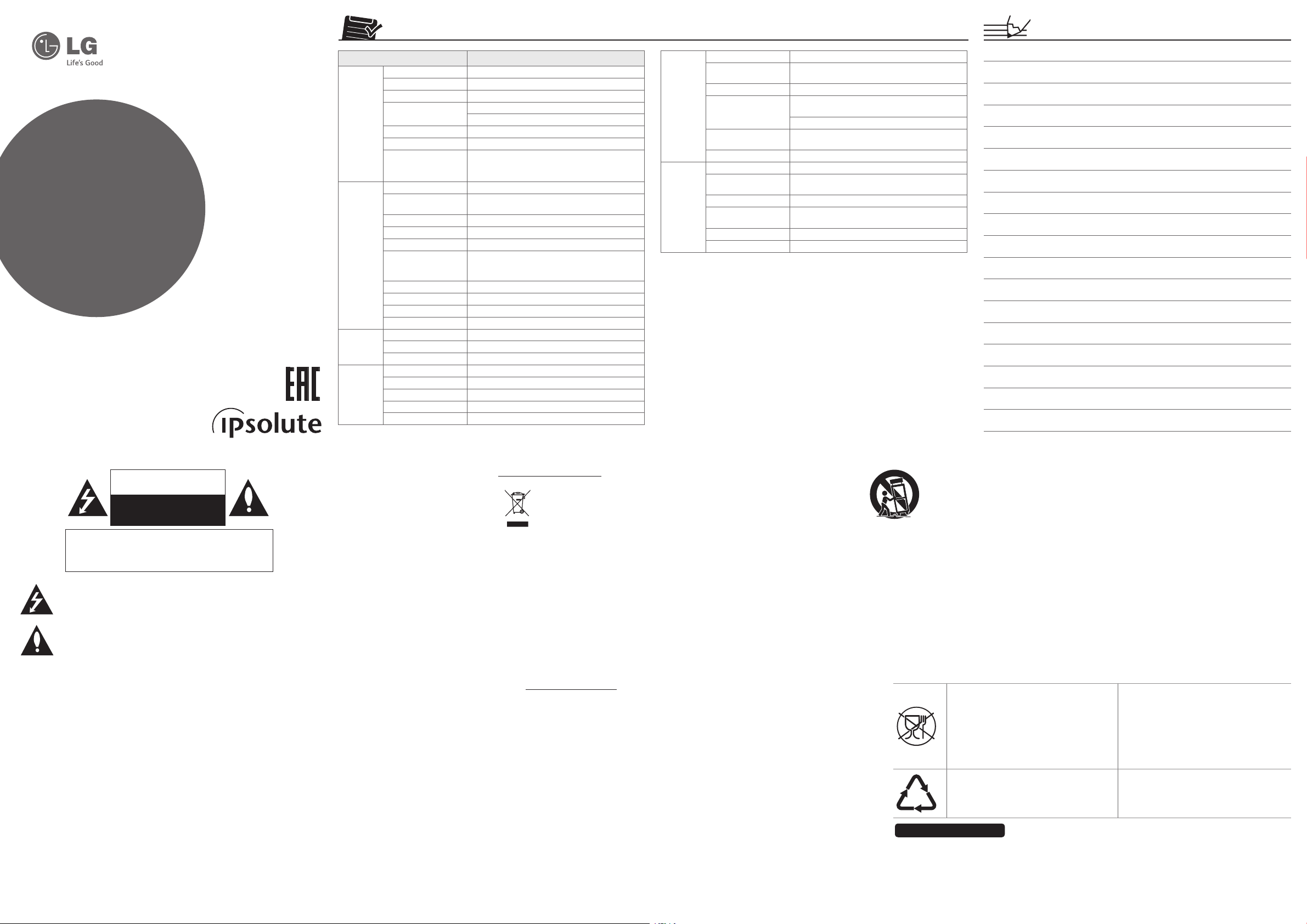
Item LNB7210 series
Image Device 6.4 mm (1/2.8 Type) CMOS
Lens Type CS mountable
Day/Night ICR (Auto / Day / Night / External / Schedule)
Minimum Illumination
WDR Support
Focus ABF
Image Enhancement
Compression H.264, H.264_High, MJPEG
Resolution
Maximum Frame Rate 60 fps @ 1920 x 1080
Multi-Streaming Up to 4
ROI (Region of Interest) Smart codec (Up to 8)
Video Analytics
Text Overlay Support
Audio Compression G.711, G.726
2-way Audio Support
Audio Detection Support
Event Trigger Video analytics, Audio detection, Alarm input
Event Notication Relay Out, Email, FTP
Pre Event Buering Support
Analog Out RCA out
Audio In/Out 1 / 1
Alarm In/Out 1 In / 1 Out
RS-485 Support
SD Slot micro SD (Up to 32 GB)
Color: 0.03 lx (F1.2, Gain : High, 1/30 sec, 50 IRE)
B/W: 0.003 lx (F1.2, Gain : High, 1/30 sec, 50 IRE)
Backlight Compensation, 2D+3D-DNR, De-fog,
Exposure Control, AGC, White Balance, Privacy Masking,
Sharpness, EIS, Pivot
1920 x 1080 / 1280 x 720 / D1 (704 x 576) /
CIF (352 x 240)
Motion detection, Tampering alarm, Face detection,
Intrusion detection, Crossing line, Object counting,
Object removal, Object desertion
Ethernet RJ-45 10 / 100 BASE-T
Security
Open Protocol ONVIF 2.2 Prole S, PSIA 1.1
Network
General
Note that design and specication of this unit may change from the manual as quality and
improvement without prior notice.
Components
Camera, CD (Software and Owner’s Manual), Installation Manual
Protocol
Integrated Software
Connections Up to 20
Power Source DC 12 V, PoE
Maximum Power
Consumption
Maximum Input Current 590 mA (DC 12 V), 150 mA (PoE)
Operation Temperature/
Humidity
Dimension (W x H x D) 69 mm x 54 mm x 136 mm
Weight 395 g
Password protection, HTTPS (SSL, TLS), IP ltering,
IEEE 802.1X
IPv4 and IPv6 : TCP/IP, UDP, HTTP, HTTPS, RTP, RTSP,
DHCP, ICMP, QoS, UPnP
IPv4 : FTP, SMTP, NTP, ARP, SNMP v1/v2c/v3, DDNS(LG)
LG Ipsolute VMS Suite / Mobile application (iPhone,
iPad, Android)
6.9 W
-10 ºC to 55 ºC / 0 % RH to 80 % RH
CAUTION
RISK OF ELECTRIC SHOCK
DO NOT OPEN
CAUTION: TO REDUCE THE RISK OF ELECTRIC SHOCK
DO NOT REMOVE COVER (OR BACK)
NO USER-SERVICEABLE PARTS INSIDE
REFER SERVICING TO QUALIFIED SERVICE PERSONNEL.
This lightning flash with arrowhead symbol within an equilateral triangle is
intended to alert the user to the presence of uninsulated dangerous voltage
within the product’s enclosure that may be of sufficient magnitude to
constitute a risk of electric shock to persons.
The exclamation point within an equilateral triangle is intended to alert the
user to the presence of important operating and maintenance (servicing)
instructions in the literature accompanying the product.
FCC WARNING: This equipment may generate or use radio frequency energy. Changes or
modifications to this equipment may cause harmful interference unless the modifications are
expressly approved in the instruction manual. The user could lose the authority to operate this
equipment if an unauthorized change or modification is made.
REGULATORY INFORMATION: FCC Part 15
This equipment has been tested and found to comply with the limits for a Class A digital device,
pursuant to Part 15 of the FCC Rules. These limits are designed to provide reasonable protection
against harmful interference when the equipment is operated in a commercial environment.
This equipment generates, uses, and can radiate radio frequency energy and, if not installed
and used in accordance with the instruction manual, may cause harmful interference to radio
communications.
Operation of this equipment in a residential area is likely to cause harmful interference in which
case the user will be required to correct the interference at his own expense.
• A suitable conduit entries, knock-outs or glands shall be provided in the cable entries of this
product in the end user.
• Holes in metal, through which insulated wires pass, shall have smooth well rounded surfaces
or shall be provided with brushings.
Warning: Do not install this equipment in a confined space such as a bookcase or similar unit.
Warning: Wiring methods shall be in accordance with the National Electric Code, ANSI/NFPA 70.
Warning: This is a class A product. In a domestic environment this product may cause radio
interference in which case the user may be required to take adequate measures.
Warning: To reduce a risk of fire or electric shock, do not expose this product to rain or moisture.
Warning: Please adopt the power adapter
which can meet the safety extra low voltage
(SELV) standard. And source with DC 12 V or
AC 24 V (depending on models) according
to the IEC60950-1 and Limited Power Source
standard.
Warning: Install the camera on a ceiling or wall
where can withstand the weight of 5 times of
the camera including mounting bracket.
Caution: This installation should be made by a
qualified service person and should conform to
all local codes.
Caution: To avoid electrical shock, do not
open the cabinet. Refer servicing to qualified
personnel only.
Caution: The apparatus shall not be exposed
to water (dripping or splashing) and no objects
filled with liquids, such as vases, shall be placed
on the apparatus.
Caution: Make sure the power supply voltage
is correct before using the camera.
Caution: Do not drop the camera or subject it
to physical shock.
Caution: The sensor may be burned out by
a laser beam, so when any laser equipment is
being used, make sure that the surface of the
sensor not be exposed to the laser beam.
Caution: While shipping, the camera should be
packed in its original packing.
Caution: It is permitted to use ancillary
equipment (e.g. A UPS) to prevent the damage
from mains supply voltage reductions.
Disposal of your old appliance
1. This crossed-out wheeled
bin symbol indicates
that waste electrical
and electronic products
(WEEE) should be disposed
of separately from the
2. Old electrical products can contain
hazardous substances so correct disposal
of your old appliance will help prevent
potential negative consequences for the
environment and human health. Your old
appliance may contain reusable parts that
could be used to repair other products,
and other valuable materials that can be
recycled to conserve limited resources.
3. You can take your appliance either to the
shop where you purchased the product,
or contact your local government waste
office for details of your nearest authorised
WEEE collection point. For the most up to
date information for your country please
see www.lg.com/global/recycling
EuSP Ltd.
Herald Way Pegasus Business Park
Castle Donington, DE74 2TZ United Kingdom
municipal waste stream.
Important Safety
Instructions
1. Read these instructions.
2. Keep these instructions.
3. Heed all warnings.
4. Follow all instructions.
5. Do not use this apparatus near water.
6. Clean only with dry cloth.
7. Do not block any ventilation openings.
Install in accordance with the
manufacturer’s instructions.
8. Do not install near any heat sources such
as radiators, heat registers, stoves, or other
apparatus (including amplifiers) that
produce heat.
9. Do not defeat the safety purpose of the
polarized or grounding-type plug. A
polarized plug has two blades with one
wider than the other. A grounding type
plug has two blades and a third grounding
prong. The wide blade or the third
prong are provided for your safety. If the
provided plug does not fit into your outlet,
consult an electrician for replacement of
the obsolete outlet.
10. Protect the power cord from being
walked on or pinched particularly at plugs,
convenience receptacles, and the point
where they exit from the apparatus.
11. Only use attachments/accessories
specified by the manufacturer.
12. Use only with the cart, stand, tripod,
bracket, or table specified by the
manufacturer, or sold with the apparatus.
When a cart is used, use caution when
moving the cart/apparatus combination
to avoid injury from tip-over.
13. Unplug this apparatus during lightning
storms or when unused for long periods
of time.
14. Refer all servicing to qualified service
personnel. Servicing is required when
the apparatus has been damaged in any
way, such as power-supply cord or plug
is damaged, liquid has been spilled or
objects have fallen into the apparatus, the
apparatus has been exposed to rain or
moisture, does not operate normally, or
has been dropped.
Российская Федерация
Импортер ООО “ЛГ Электроникс Рус”
Адрес импортера: 143160 Российская Федерация, Московская область, Рузский район, сельское поселение Дороховское,
Адрес производителя : ЛГ ЭЛЕКТРОНИКС (ХУЖОУ) ИНК., ЗАВОД ХАТАИ
Handling of the unit
Be careful not to spill water or other liquids on
the unit. Be cautious not to get combustible or
metallic material inside the body. If used with
foreign matter inside, the camera is liable to fail
or to get cause of fire or electric shock.
• Remove dust or dirt on the surface of the
lens with a blower.
• Use a soft and lint-free, dry cloth(such as
glass cleaner) to clean the body. If it is
very dirty, use a cloth dampened with a
small quantity of neutral detergent then
wipe dry.
• Avoid the use of volatile solvents such
as thinners, alcohol, benzene and
insecticides.
They may damage the surface finish and/
or impair the operation of the camera.
• This camera is designed for mounting on
the ceiling or wall. If you install this camera
upside down, it may cause malfunction.
Символ «не для пищевой продукции»
применяется в соответствие с техническим
регламентом Таможенного союза «О
безопасности упаковки» 005/2011 и указывает
на то, что упаковка данного продукта не
предназначена для повторного использования
и подлежит утилизации. Упаковку данного
продукта запрещается использовать для
хранения пищевой продукции.
Символ «петля Мебиуса» указывает на
возможность утилизации упаковки. Символ
может быть дополнен обозначением материала
упаковки в виде цифрового и/или буквенного
обозначения.
86 км. Минского шоссе, д.9
ЛГ Электроникс (Хужоу) Инк., завод Хатаи
516006, Китай, пров. ГуанДонг, г. Хужоу, Промышленная зона
Жонгкай, Индустриальный парк Хутаи, ХуФенг Донг Уи Роуд, 13.
Символ Кедендік одақтың 005/2011
техникалық регламентіне сәйкес
қолданылады және осы өнімнің қаптамасын
екінші рет пайдалануға арналмағанын және
жоюға жататынын көрсетеді. Осы өнімнің
қаптамасын азық-түлік өнімдерін сақтау үшін
пайдалануға тыйым салынады.
Символ қаптаманы жою мүмкіндігін көрсетеді.
Символ сандық код және/немесе әріп
белгілері түріндегі қаптама материалының
белгісімен толықтырылуы мүмкін.
Operating and storage
location
Avoid viewing a very bright object (such as
light fittings) during an extended period. Avoid
operating or storing the unit in the following
locations.
• Extremely hot or cold places (operating
temperature -10 °C to 55 °C, however, we
recommend that the unit be used within a
temperature range of 0 °C to 45 °C)
• Damp or dust place
• Places exposed to rain
• Places subject to strong vibration
• Close to generators of powerful
electromagnetic radiation such as radio or
TV transmitters.
• Do not use the camera in such place
where rapid temperature fluctuation by
switching an air conditioner on and off.
Сделано в Китае
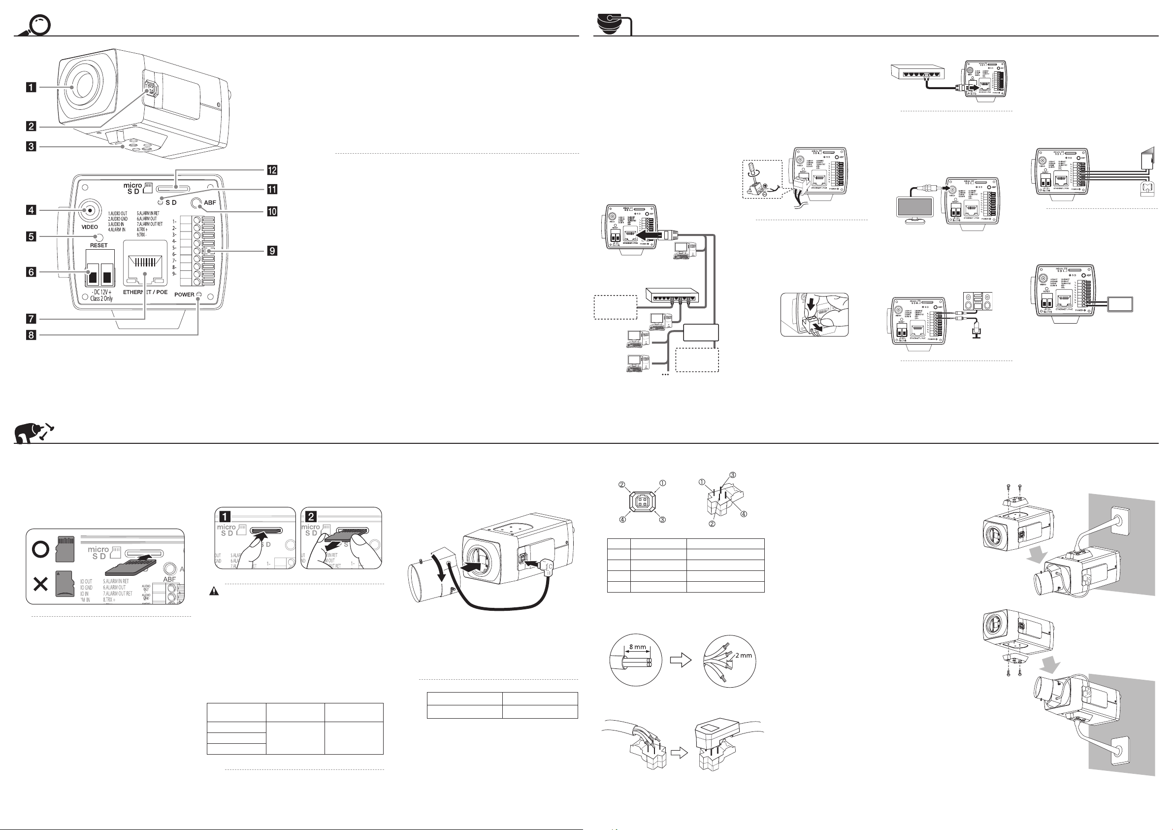
Part Names and Functions
a
b
c
d
e
f
g
h
a Cap
b Lens iris output connector (LENS)
This 4- pin connector is used to send the Iris control signal and power supply to an auto-iris
type lens.
l
k
j
i
Camera installation hole
c
d VIDEO OUT
e RESET button
Push the button more than 3 seconds, this would restore the factory default network related
settings.
Power input terminal
f
Connects to a DC 12 V power supply using proper cables. This camera must always be operated
a DC 12 V. Certied/Listed Adaptor which comply with LPS.
ETHERNET/PoE Port
g
Connects to a PC or a network via a hub with a 10 BASE-T / 100 BASE-TX cable attached RJ-45
connector.
Power over Ethernet (PoE) is a technology that integrates power into a standard LAN
,
infrastructure. It enables power to be provided to the network device, such as a network
camera, using the same cable as that used for network connection. It eliminates
the need for power outlets at the device locations and enables easier application of
uninterruptible power supplies (LPS).
h Power indicator
Lights when the camera is powered.
i External device connectors
• AUDIO OUT: Connect to an active speaker with a built-in amplier.
• AUDIO IN: Input for a mono microphone, or a line-in mono signal.
• ALARM IN/ALARM IN RET (Sensor input) Terminals: Provides physical interface for sensor.
External Day/Night fucntion is supported as using ALARM IN.
• ALARM OUT/ALARM OUT RET Terminals: Provides physical interface for Alarm/Relay.
• RS-485 (TRX+/TRX-): Connect an external PTZ device.
j
ABF Auto Back Focus
ABF Auto Back Focus is an adjustable function for the back focus automatically. Keep pressing
this button about 4 seconds to be activated the focus reset function and set the zoom and
focus of the lens approximately. If you press this button, the camera will be activated to adjust
the back focus automatically.
micro SD card condition indicator
k
Lights when the micro SD card is activated normally. Blinks when the recording is in progress
on the micro SD card.
micro SD card slot
l
Connection
Precautions
• Be sure to switch o the unit before
installation and connection.
• The installation should be made by qualied
service personnel or system installers.
• Do not expose the power and connection
cables to moisture, which may cause
damage to the unit.
Connecting Network
You can control and monitor the system via
network. With the remote control (monitoring),
you can change the system conguration
or monitor the image via network. After the
installation, check the network settings for the
remote control and monitoring work.
Connect the IP camera to your network using a
standard RJ-45 network cable as shown below.
PoE Device
(IEEE802.3af )
Broadband
Service
Router
Broadband
Service
Connecting Power Source
Connect power, using one of the methods
listed below:
To use the power adapter
Connect a DC 12 V power source to the power
input terminal as shown below.
(Recommended power adapter is DC 12 V /
1.5 A or above)
Connect a power source to the power input
terminal with 2 and 3 aligned correctly as
shown below.
• When the connecting Alarm and
,
Audio, tighten the screws as shown
above.
• To remove the connector plug,
as shown below. Put your nger
between the power connector and
the camera body to pull out the
connector.
To use the PoE (Power over Ethernet) device
Connect the PoE cable to the LAN port on the
unit. You must use the “IEEE802.3af” standard
PoE device.
PoE Device
(IEEE802.3af )
If the camera doesn’t work properly after
,
connecting PoE device, please check if
the PoE device supplies enough power.
Connecting Display Device
Connect the video signal between the IP
camera and the monitor.
Connecting Microphone and
Speaker Device
Optionally connect an active speaker and/or
external microphone with a built-in amplier.
Audio OUT
Audio IN
Keep the microphone away from the
,
speaker to avoid howling.
Connecting Alarm Device
Alarm terminals are used to connect the alarm
(relay) devices such as sensors, door switches,
etc.
ALARM IN & OUT / ALARM IN & OUT Ret
(Sensor Input / Relay Output)
Connect the sensor device to the sensor input
terminal.
Connect the alarm (relay) device to the relay
output terminal. Alarm signal is outputted at an
event occurrence.
Sensor
Device
Alarm (relay)
Device
The Photo MOS Relay is rated for
,
100 mA at DC 20 V or 100 mA at AC 28 V.
Connecting PTZ Device
You can control the Pan, Tilt, Zoom, Focus and
Preset when the PTZ device is connected.
PTZ
Device
Installation
Using the micro SD card
You can record your surveillance environment with the micro SD
card even if the network is disconnected condition.
To insert the micro SD card
Insert the micro SD card carefully as shown in the following
illustrations. Make sure the micro SD card terminal position
before insert the micro SD card. Push the back end of the micro
SD card to x it at the last step.
• Do not use the power too much when you insert the
,
micro SD card. The micro SD card may be damaged.
• If you insert the micro SD card in the wrong position,
the micro SD card may be damaged or it may cause
the malfunction of the micro SD Card Slot.
• Keep the terminal part of the micro SD card in clean.
Be careful the terminal part of the micro SD card not
to dusty.
• As the micro SD card is consumable, the micro SD
card end its days and may be not able to save data if
you use it more than over certain times. In this case,
replace micro SD card to buy a new one.
Remove the micro SD card
1. Press the back end of the micro SD card to release the lock
condition.
2. Take the micro SD card out carefully from the camera. It may
cause a malfunction of the micro SD card or the micro SD
card slot if you use the power too much at lock status.
• If you install the micro SD card on the camera
and remove with the micro SD card condition
indicator lights on, you must unmount the micro
SD card by using the [System > Storage > Device
Management > Unmount] menu. The micro SD
card data is compromised or the camera may not
operate normally, if you remove the card without use
[Unmount] function.
• LG Electronics is not responsible for deleted data
caused by user mishandling when you insert or
remove the micro SD card.
Recommended the micro SD card specication
Maker Capacity
LG
Less than 32 GB 32 kbyteSandisk
Transcend
Block Size
(FAT 32)
Mounting the Lens
1. Remove the lens mount cap from the camera.
2. Install the CS mount type lens. Carefully align the lens
mount with the camera opening, then turn the lens slowly
to install it. The proper installation is that you face each at
(non-hood) side toward the corner.
3. Connect the lens plug to the lens iris output connector
(LENS) on the side of the camera. When using lenses from
other makers, the plug shape may not correspond to the
terminal on the camera. In such a case, remove the original
plug and using a soldering iron, connect a lens iris plug
according to the diagram.
• Recommended DC-Iris Lens
,
Maker Model name
FUJINON YV2.1x2.8SR4A-SA2L
• We recommend using 6mm (1/3 type)
Lens of 2 Mega Pixel or above.
Lens iris output connector
Pin layout for the lens iris output connector.
No. DC type lenses VIDEO type lenses
1 Damping - Vcc (+9 V)
2 Damping + Not used
3 Drive + Video
4 Drive - Ground
Rewire the lens iris plug
1. Cut o the plug of the lens cable, cut o approximately 8
mm of the insulation, and then strip approximately 2 mm of
the ends of the cable sheaths.
2. Solder the ends of the cable wires to the ends of the pins,
and then attach the cover of the lens iris plug.
Focus adjustment
After installing the lens, you should adjust the focus as shown
below steps.
1. Keep pressing ABF button about 4 seconds.
2. Adjust approximate zoom and focus level of the lens
manually.
3. Press ABF button to adjust the focus automatically.
Camera Installation
Select a location that is strong enough to bear the full weight
and install the camera securely.
*MFL69458103*
Speed of reading and writing more than 10 MB/Second
,
(Class 6)
 Loading...