

LG CB777F-AA, CB777F-NA, LN777F, CB777F-EA, StudioWorks 700S Service Manual
...
COLOR MONIT OR
SER VICE MANUAL
Website:http://biz.LGservice.com
E-mail:http://www.LGEservice.com/techsup.html
CAUTION
BEFORE SERVICING THE UNIT,
READ THE SAFETY PRECAUTIONS IN THIS MANUAL.
MENU SELECT
MODEL:
StudioWorks 700S (CB777F-NA), StudioWorks 700E (CB777F-AA)
StudioWorks 700B (CB777F-EA), LN777F(LN777F)
CHASSIS NO. : CA-90
F ACTORY MODEL: CB777F
*( ) ID LABEL Model No.
1. PICTURE TUBE
Size : 17 inch (Flat Square Tube)
DefIection Angle : 90°
Neck Diameter : 29.1 mm
Dot Pitch : 0.27 mm
Face Treatment : W-ARASC (Anti-Reflection and
Anti-Static Coating),
Anti-static coating
Low Radiation : MPR II, TCO 99
2. SIGNAL
2-1. Horizontal & Vertical Sync
1) Input Voltage Level: Low=0~1.2V, High=2.5~5.5V
2) Sync Polarity : Positive or Negative
2-2. Video Input Signal
1) Voltage Level : 0 ~ 0.7 Vp-p
a) Color 0, 0 : 0 Vp-p
b) Color 7, 0 : 0.467 Vp-p
c) Color 15, 0 : 0.7 Vp-p
2) Input Impedance : 75 Ω
3) Video Color : R, G, B Analog
4) Signal Format : Refer to the Timing Chart
2-3. Signal Connector
3 row 15-pin Connector (Attached)
2-4. Scanning Frequency
Horizontal : 30 ~ 70 kHz
Vertical : 50 ~ 160 Hz
3. POWER SUPPLY
3-1. Power Range
AC 100~240V (Free Voltage), 50/60Hz, 2.0A Max.
3-2. Power Consumption
4. DISPLAY AREA
4-1. Active Video Area :
• Max Image Size - 326.7 x 245.5 mm (12.86" x 9.67")
• Preset Image Size - 310 x 230 mm (12.20" x 9.06")
4-2. Display Color : Full Colors
4-3. Display Resolution : 1280 x 1024 / 60Hz
(Non-Interlace)
4-4. Video Bandwidth : 110 MHz
5. ENVIRONMENT
5-1. Operating Temperature: 15°C ~ 30°C (59°F ~ 86°F)
(Ambient)
5-2. Relative Humidity : 8%~ 80%
(Non-condensing)
5-3. Altitude : 5,000 m
6. DIMENSIONS (with TILT/SWIVEL)
Width : 400.0 mm (15.74 inch)
Depth : 420.0 mm (16.53 inch)
Height : 395.0 mm (15.55 inch)
7. WEIGHT (with TILT/SWIVEL)
Net Weight : 14.4 kg (31.75 lbs.)
Gross Weight : 17.0 kg (37.48 lbs.)
CONTENTS
- 2 -
SPECIFICATIONS ................................................... 2
SAFETY PRECAUTIONS ........................................ 3
TIMING CHART ....................................................... 4
OPERATING INSTRUCTIONS ................................ 5
CONTROL LOCATIONS ......................................... 6
WIRING DIAGRAM ................................................. 7
DISASSEMBLY ....................................................... 8
BLOCK DIAGRAM ................................................. 11
DESCRIPTION OF BLOCK DIAGRAM...................12
ADJUSTMENT ...................................................... 14
TROUBLESHOOTING GUIDE .............................. 16
EXPLODED VIEW...................................................26
REPLACEMENT PARTS LIST ............................... 28
PIN CONFIGURATION........................................... 34
SCHEMATIC DIAGRAM......................................... 36
PRINTED CIRCUIT BOARD................................... 38
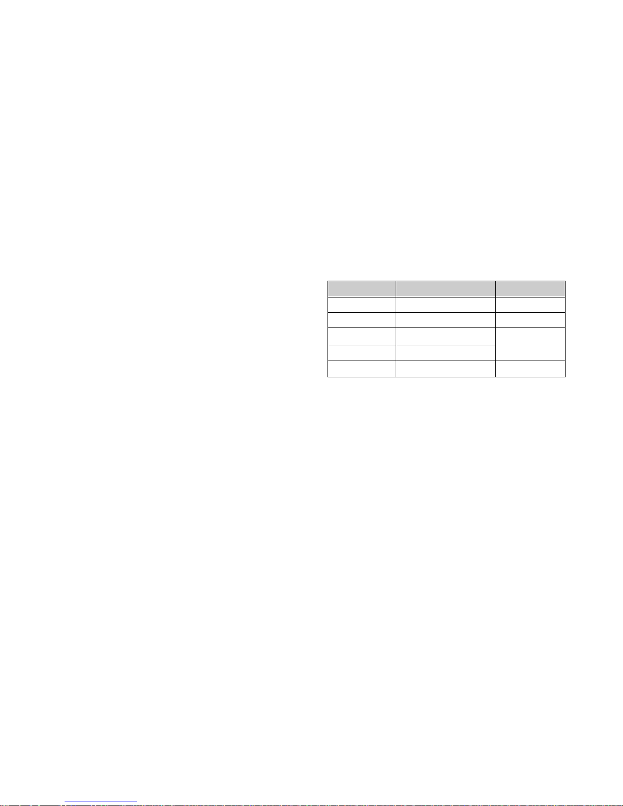
SPECIFICATIONS
MODE
MAX
NORMAL (ON)
STAND-BY
SUSPEND
OFF
POWER CONSUMPTION
100 W
74 W
less than 15 W
less than 15 W
less than 5 W
LED COLOR
GREEN
GREEN
AMBER
AMBER

SAFETY-RELATED COMPONENT WARNING!
There are special components used in this color monitor
which are important for safety. These parts are marked
on the schematic diagram and the replacement
parts list. It is essential that these critical parts should be
replaced with the manufacturer's specified parts to
prevent X-radiation, shock, fire, or other hazards. Do not
modify the original design without obtaining written
permission from LG or you will void the original parts and
labor guarantee.
CAUTION:
No modification of any circuit should be
attempted.
Service work should be performed only after
you are thoroughly familiar with all of the
following safety checks and servicing
guidelines.
SAFETY CHECK
Care should be taken while servicing this color monitor
because of the high voltage used in the deflection circuits.
These voltages are exposed in such areas as the
associated flyback and yoke circuits.
FIRE & SHOCK HAZARD
An isolation transformer must be inserted between the
color monitor and AC power line before servicing the
chassis.
• In servicing, attention must be paid to the original lead
dress specially in the high voltage circuit. If a short
circuit is found, replace all parts which have been
overheated as a result of the short circuit.
• All the protective devices must be reinstalled per the
original design.
• Soldering must be inspected for the cold solder joints,
frayed leads, damaged insulation, solder splashes, or
the sharp points. Be sure to remove all foreign
materials.
IMPLOSION PROTECTION
All used display tubes are equipped with an integral
implosion protection system, but care should be taken to
avoid damage and scratching during installation. Use only
same type display tubes.
X-RADIATION
The only potential source of X-radiation is the picture tube.
However, when the high voltage circuitry is operating
properly there is no possibility of an X-radiation problem.
The basic precaution which must be exercised is keep the
high voltage at the factory recommended level; the normal
high voltage is about 25.5kV. The following steps describe
how to measure the high voltage and how to prevent Xradiation.
Note : It is important to use an accurate high voltage
meter calibrated periodically.
• To measure the high voltage, use a high impedance
high voltage meter, connect (–) to chassis and (+) to
the CDT anode cap.
• Set the brightness control to maximum point at full
white pattern.
• Measure the high voltage. The high voltage meter
should be indicated at the factory recommended level.
• If the meter indication exceeds the maximum level,
immediate service is required to prevent the possibility
of premature component failure.
• To prevent X-radiation possibility, it is essential to use
the specified picture tube.
CAUTION:
Please use only a plastic screwdriver to protect yourself
from shock hazard during service operation.
SAFETY PRECAUTIONS
- 3 -
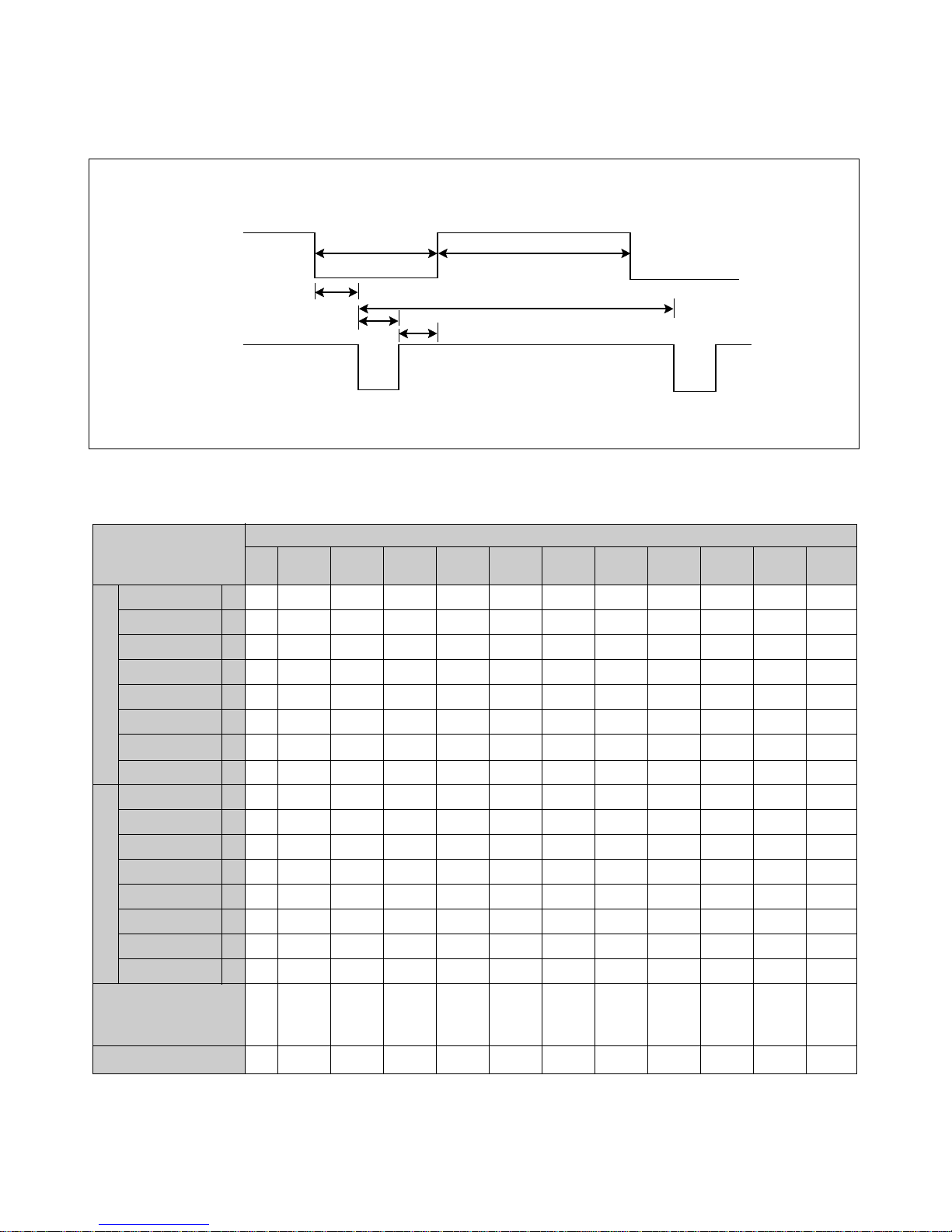
TIMING CHART
- 4 -
VIDEO
SYNC
C
E
D
F
AB
MODE
Resolution
Recall
H
O
R
I
Z
O
N
T
A
L
V
E
R
T
I
C
A
L
kHz
µs
µs
µs
µs
µs
µs
Hz
ms
ms
ms
ms
ms
ms
MODE 2
+
46.88
21.33
16.16
5.17
0.32
1.62
3.23
+
75.01
13.331
12.798
0.533
0.021
0.064
0.448
800
x
600
75Hz
Yes
MODE 1
—
37.50
26.67
20.32
6.35
0.51
2.03
3.81
—
74.99
13.335
12.802
0.533
0.026
0.080
0.427
640
x
480
75Hz
Yes
MODE 3
+
53.68
18.63
14.22
4.41
0.57
1.14
2.70
+
85.07
11.775
11.178
0.577
0.018
0.056
0.503
800
x
600
85Hz
Yes
MODE 4
+
68.677
14.561
10.836
3.725
0.508
1.016
2.201
+
85.00
11.764
11.182
0.582
0.014
0.044
0.524
1024
x
768
85Hz
Yes
MODE 5
—
31.47
31.78
25.42
6.36
0.64
3.81
1.91
+
70.08
14.269
12.712
1.557
0.414
0.063
1.080
640
x
400
70Hz
Yes
MODE 6
—
31.47
31.78
25.42
6.36
0.64
3.81
1.91
—
59.94
16.684
15.254
1.430
0.318
0.063
1.049
640
x
480
60Hz
Yes
MODE 7
+
37.88
26.40
20.00
6.40
1.00
3.20
2.20
+
60.32
16.579
15.840
0.739
0.026
0.106
0.607
800
x
600
60Hz
Yes
MODE 8
—
43.269
23.112
17.778
5.334
1.556
1.556
2.222
—
85.008
11.764
11.093
0.670
0.023
0.069
0.578
640
x
480
85Hz
Yes
MODE 9
—
49.75
20.10
14.52
5.58
0.55
1.12
3.91
—
74.95
13.407
12.542
0.865
0.021
0.060
0.784
832
x
624
75Hz
Yes
MODE 10
+
60.02
16.66
13.00
3.66
0.20
1.22
2.24
+
75.03
13.328
12.795
0.533
0.017
0.050
0.466
1024
x
768
75Hz
Yes
MODE 11
+
63.98
15.63
11.85
3.78
0.44
1.04
2.30
+
60.02
16.661
16.005
0.656
0.015
0.047
0.594
1280
x
1024
60Hz
Yes
MARK
E
A
B
C
D
F
E
A
B
C
D
F
Sync Polarity
Frequency
Total Period
Video Active Time
Blanking Time
Front Porch
Sync Duration
Back Porch
Sync Polarity
Frequency
Total Period
Video Active Time
Blanking Time
Front Porch
Sync Duration
Back Porch
FACTORY PRESET MODE
* Mode 1~Mode 4: Preset Mode (Mode 5~Mode 11: Default Mode)
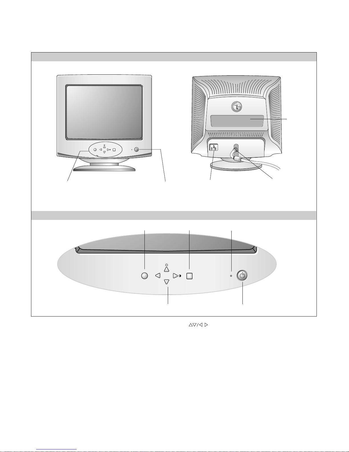
OPERATING INSTRUCTIONS
- 5 -
MENU SELECT
FRONT VIEW REAR VIEW
AC Power Socket
Signal Connector
ID Label
Power ON/OFF Button
See Front Control Panel
Front Control Panel
1. Power ON/OFF Button
Use
this button to turn the monitor ON or OFF.
2. Power Indicator
This indicator lights up green when the monitor operates
normally; in DPMS (Energy Saving) mode, - stand-by,
suspend, or power off mode - its color changes to orange,
and if abnormal or damaging circuit turns out orange blink.
3. Select Button
Use this button to enter a selection in the on screen
display.
4. Button
Use these buttons to choose or adjust items in the on
screen display.
5. MENU Button
Use this button to enter or exit the on screen display.
MENU SELECT
4
5
1
2
3
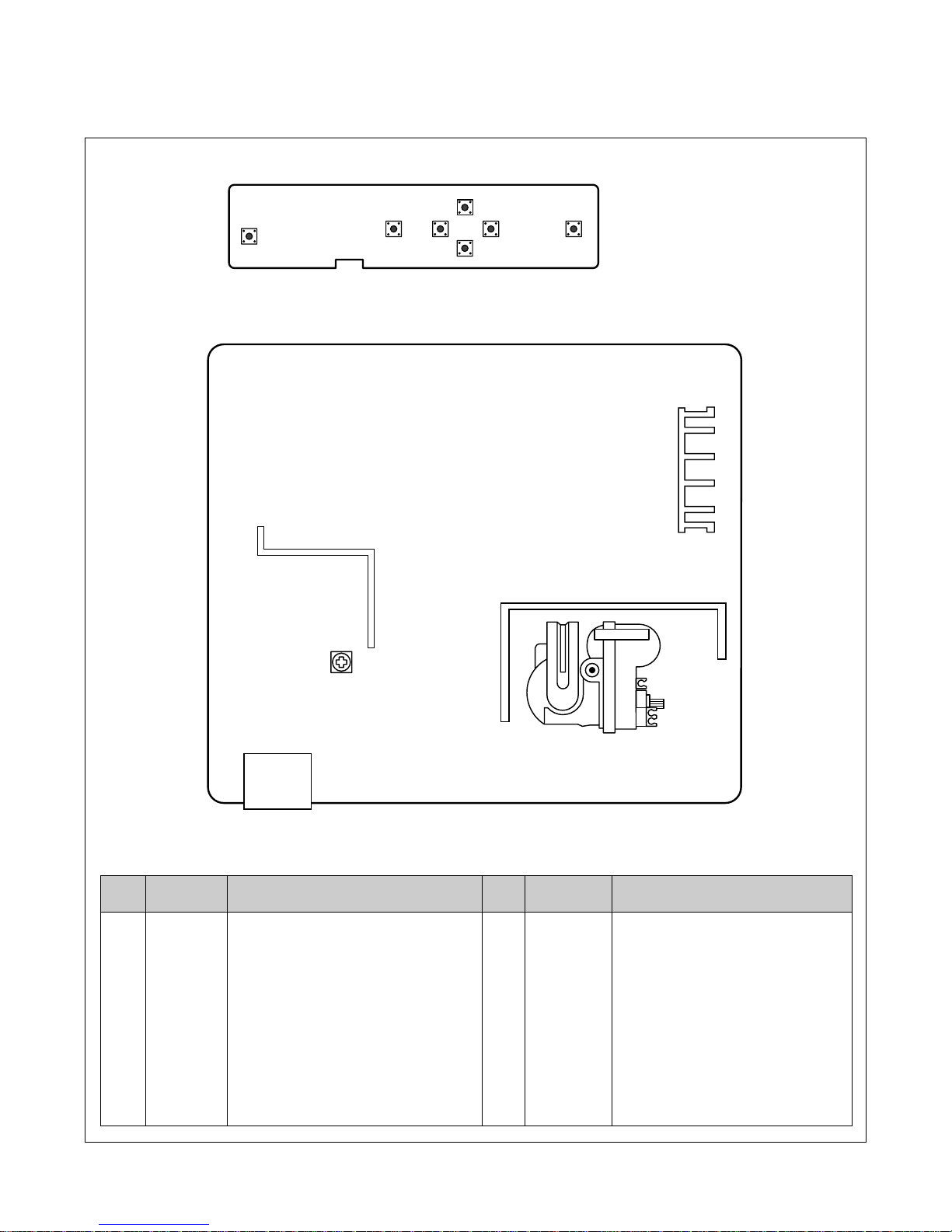
CONTROL LOCATIONS
- 6 -
MAIN
FBT
CONTROL
1
2
3
4
5
7
6
8
NO.
1
2
3
4
5
Ref. No.
SW207
SW204
SW205
SW203
SW206
NO.
6
7
8
Ref. No.
SW202
SW201
VR901
Control Function
POWER
BUTTON
OSD SELECT
OSD ADJUSTMENT(UP)
OSD ADJUSTMENT(DAUN)
OSD ADJUSTMENT(LEFT)
Control Function
OSD ADJUSTMENT(RIGHT)
MENU BUTTON
B+ ADJUSTMENT
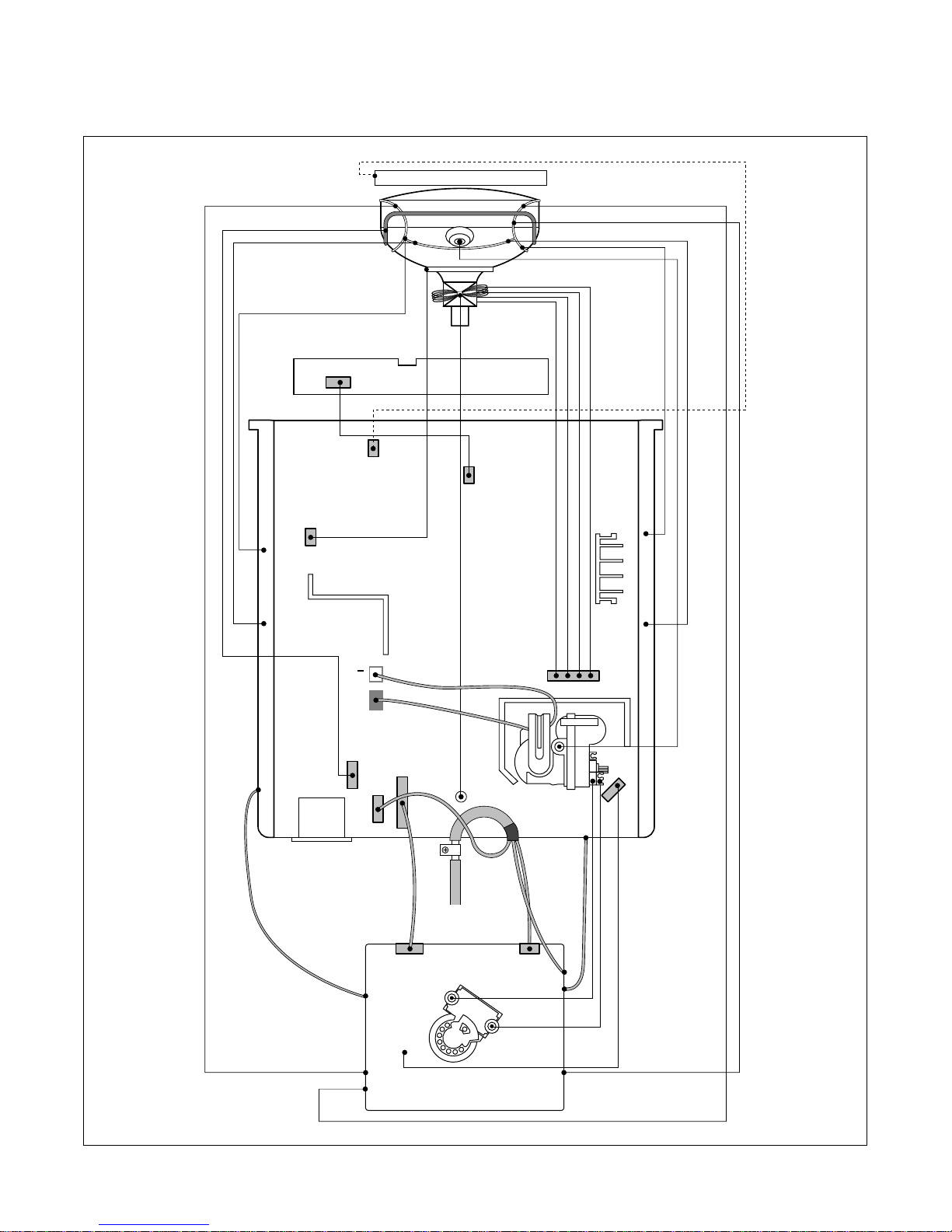
WIRING DIAGRAM
- 7 -
P501
P201
CABINET
P405
P102
P301
P302
P702
P402
P902
S
+
S
TO G2
Signal
Cable
AC
Socket
FBT
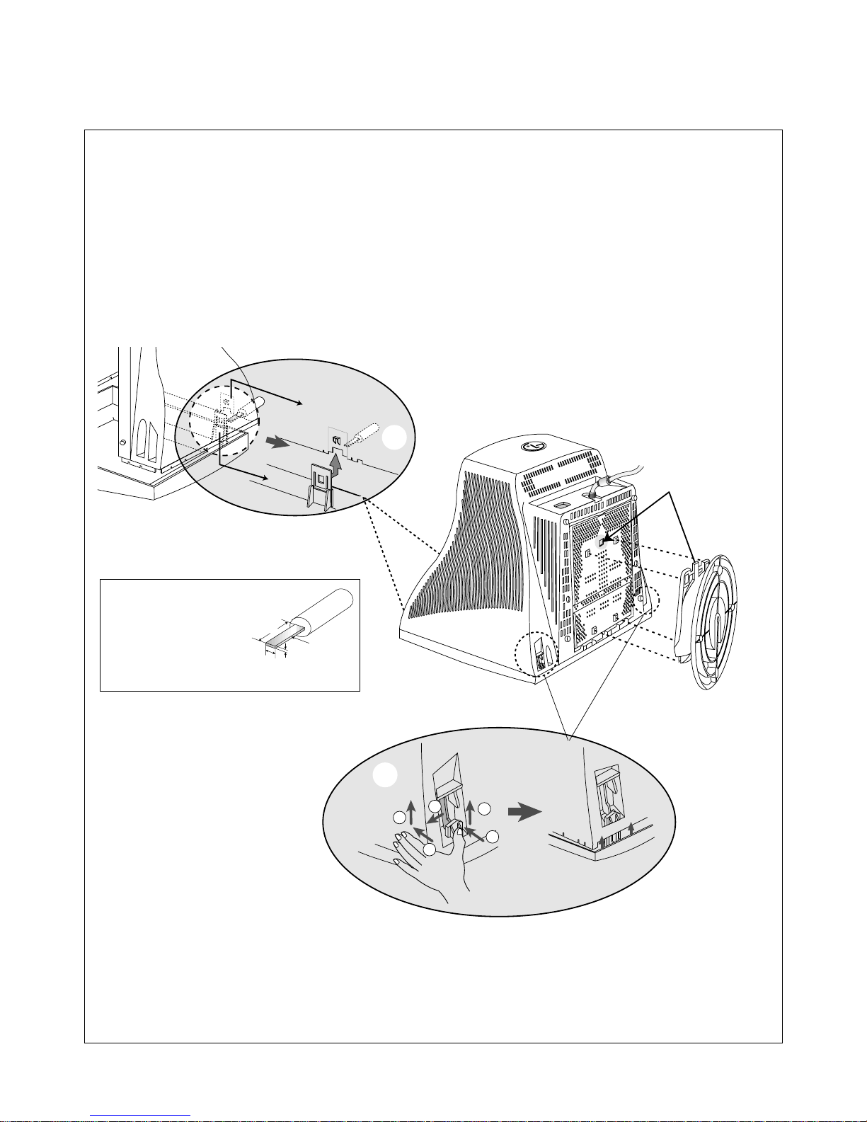
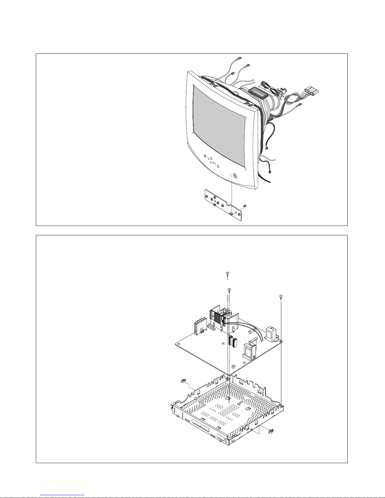
DISASSEMBLY
- 8 -
1. TILT/SWIVEL & BACK COVER REMOVAL
1) Set the monitor face downward.
2) Pressing the latch (a), carefully remove the Tilt/Swivel by pulling it upward.
3) Pressing the latch (b), Back cover by pushing it upward.
4) Release the latch (c).
5) Slide the Back Cover away from the Front Cabinet of the monitor.
Tip Spec.
A(Width) : 5.0~15.0mm
B(Depth) : 0.6~0.9mm
C(Height) : 10.0mm
Back Cover
(c)
Cabinet
(a)
C
Tip
B
A
(b)
1
3
2
3
2
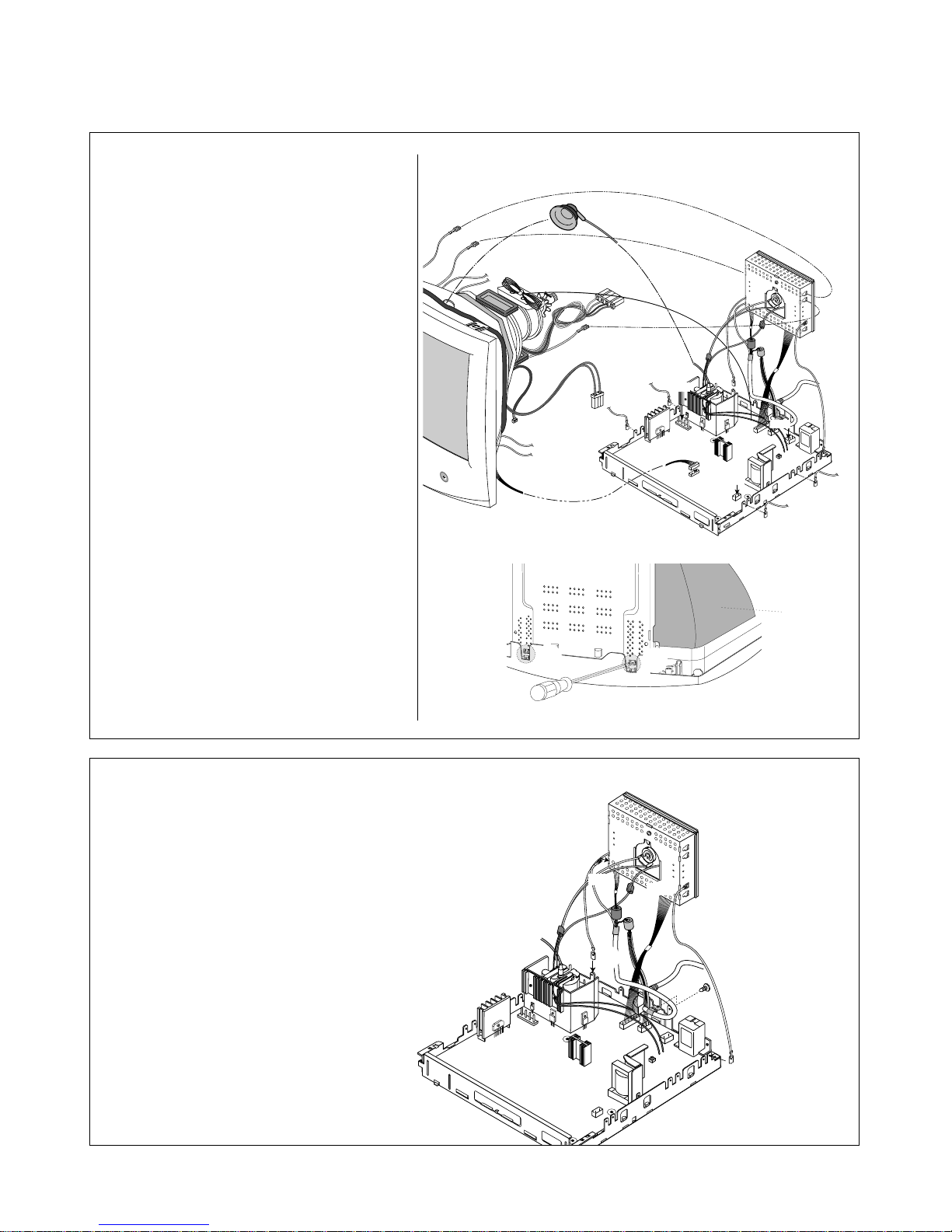
- 9 -
(b)
(a)
(a)
(a)
P302
P301
3. VIODEO PCB ASSEMBLY REMOVAL
1) Disconnect P301, P302 from the Video PCB.
2) Remove three connects (a).
3) Remove screws (b).
4) Remove the Video PCB Assembly.
2. TOTAL CHASSIS ASSEMBLY REMOVAL
(
Figure.1)
1) Carefully separate the CDT Board
Assembly from the CDT neck.
2) Discharge the remaining static electricity
by shorting between the Anode Cap and
the CDT ground.
3) Disconnect the Anode Cap from the
CDT.
4) Disconnect P902 (Degaussing pin),
P701 (DY pin), and P501, P405 from
the Main PCB.
5) Remove the Total Chassis
Assembly from the Main Frame.
(
Figure.2)
6) Set the monitor face downward.
7) Pressing the latch (a), Main Chassis
by pushing it upward.
Anode Cap
P501
to Tilt coil
(P501)
Degaussing pin
(P902)
P902
T
P701
P201
(Control PCB)
P405
(a)
(a)
CDT
Figure.1
Figure.2
- 10 -
(b)
(b)
(b)
(a)
(a)
5. BOTTOM BRACKET REMOVAL
1) Remove two holer (a).
2) Remove three screw (b).
3) Remove the Bottom Bracket.
MENU
SELECT
(a)
4. CONTROL PCB ASSEMBLY REMOVAL
1) Remove the screw (a).
2) Remove the Control PCB.
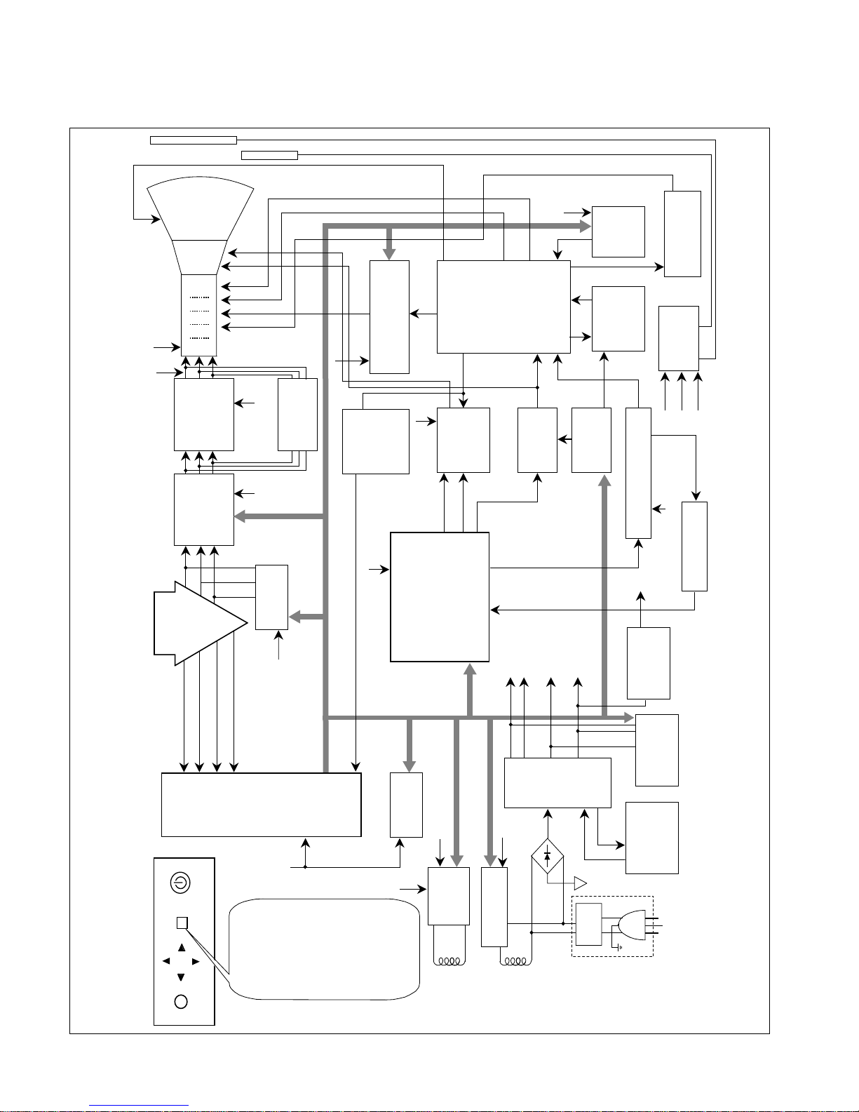
BLOCK DIAGRAM
- 11 -
OSD
ON/OFF
SELECT
POWER
POWER INPUT
100~240VAC
(50/60Hz)
Line
Filter
Degaussing
Circuit
< OSD Control >
SMPS
TRANS
(T901)
SMPS
CONTROL
(IC901)
DPM
CONTROL
CIRCUIT
5V
Voltage
Regulating
Circuit
80V
50V 15V
6.3V
TILT
Control
Circuit
6.3V
15V
E
2
PROM
(IC402)
H / V POSITION
H / V SIZE
SPCC
TRAPIZODE
PIN BALANCE
PARALLELOGRAM
ROTATION
RECALL
DEGAUSS
DDC OPTION
COLOR CURVE
MOIRE
LANGUAGE
RECALL
VIDEO LEVEL
BRIGHTNESS CONTROL
OSD POSITION
5V
OSD IC
(IC301)
H-Sync Sig
V-Sync Sig
I
2
C DATA(SDA)
I
2
C CLOCK(SCL)
VIDEO
PRE-AMP
(IC302)
Signal
Cable
R
G
B
VIDEO
CUT OFF IC
(IC304)
MAIN AMP
(IC303)
5V
5V
H/V Sync Processor
( IC701 )
TDA4841
V-OUT
( IC601)
TDA4866
H-OUT
( Q706)
H-Linearity
Correction
Screen Control
Circuit
DC/DC Converter
X-RAY
Protection
Circuit
FBT
( T701 )
Dynamic
Focus
Circuit
TCO
Auto
Beam
Limit
Vertical Blanking,
Brightness Control
- 157V
40V
300V
600V
15V
D/D Feed Back
12V
MICOM
(IC401)
SCL / SDA
H/V Sync,
PWM Control
15V
5V
15V
80V
15V
50V
DY CDT
Heater ( 6.3V )
I
2
C
I
2
C
I
2
C
H/V
Sync
G
1
Screen
Dynamic Focus
Static Focus
H.V
R/G/B
Drive/Contrast
Cut-Off
H-DRV
B-DRV
In
Out
B+
15V
TILT
COIL
DEGAUSSING
COIL
I
2
C
Vout 1
Vout 2
105V
40V
15V

DESCRIPTION OF BLOCK DIAGRAM
- 12 -
1. Line Filter & Associated Circuit.
This is used for suppressing noise of power input line
flowing into the monitor and/or some noise generated in
this monitor flowing out through the power input line.
That is to say, this circuit prevents interference between
the monitor and other electric appliances.
2. Degauss Circuit & Coil.
The degauss circuit consists of the degaussing coil, the
PTC(Positive Temperature Coefficient) thermistor(TH901),
and the relay(RL901). This circuit eliminates abnormal
color of the screen automatically by degaussing the
shadow mask in the CRT during turning on the power
switch. When you need to degauss in using the monitor,
select DEGAUSS on the OSD menu.
3. SMPS(Switching Mode Power Supply).
This circuit is working of 90~264V AC(50/60Hz).
The operation procedure is as follows:
1) AC input voltage is rectified and smoothed by the
bridge diodes (D900) and the capacitor (C908).
2) The rectified voltage(DC) is applied to the primary
coil of the transformer(T901).
3) The control IC(IC901) generates switching pulse to
turn on and off the primary coil of the transformer
(T901) repeatedly.
4) Depending on turn ratio of the transformer, the
secondary voltages appear at the secondary coils of
the transformer(T901).
5) These secondary voltages are rectified by each
diode(D941, D942, D951, D961, D962, D971) and
operate other circuit. (horizontal and vertical deflection,
video amplifier, ...etc.)
4. X-ray Protection.
I
f the high voltage of the FBT reaches up to 29kV (abnormal
state), Q807 operates and IC401(MICOM) pin 41 come to
low level. Then MICOM control IC701 (Deflection controller)
to stop Horizontal drive pulse and stop Horizontal Deflection.
5. Micom(Microprocessor) Circuit.
The operating procedure of Micom(Microprocessor) and its
associated circuit is as follows:
1) H and V sync signal is supplied from the signal cable.
2) The Micom(IC401) distinguishes polarity and
frequency of H and V sync.
3) The Micom sets operating mode and offers the
controlled data. (H-size, H-position, V-size, ... etc.)
4) The controlled data of each mode is stored in itself.
5) User can adjust screen condition by each OSD
function. The data of the adjusted condition is stored
in EEPROM(IC402).
6. Horizontal and Vertical Oscillation.
This circuit generates the horizontal pulse and the vertical
pulse by taking the H and V sync signal.
This circuit consists of the TDA4841(IC701) and the
associated circuit.
7. D/D(DC to DC) Converter.
This circuit supplies DC voltage to the horizontal deflection
output circuit by increasing DC 50V which is the
secondary voltage of the SMPS in accordance with the
input horizontal sync signal.
8. Horizontal Deflection Output Circuit.
This circuit makes the horizontal deflection by supplying
the saw-tooth current to the horizontal deflection yoke.
9. High Voltage Output & FBT(Flyback Transformer).
The high voltage output circuit is used for generating pulse
to the primary coil of the FBT(Flyback Transformer
(T701)). A boosted voltage(about 25.5kV) appears at the
secondary of the FBT and it is supplied to the anode,
focus, and screen voltage of the CRT.
10. H-Linearity Correction Circuit.
This circuit corrects the horizontal linearity for each
horizontal sync frequency.
11. Vertical Output Circuit.
This circuit inputs the vertical ramp ware from the
IC701(TDA4841) to the IC601(TDA4866) and amplifies,
supplies the saw-tooth current to the vertical deflection
yoke(V-DY).
12. Dynamic Focus Output Circuit.
This circuit amplifies the focus output ware of
IC701(TDA4841) pin 32 at the Q710 circuit, and then
superpositioning with H signal of T702, supplies it to the
FBT(T701). Therefore this circuit maintains constant focus
on center and corners in the screen.
13. H& V Blanking and Brightness Control.
Blanking circuit eliminates retrace line by supplying
negative pulse to the G1 of the CRT. And Brightness
circuit is used for control of the screen brightness by
changing DC level of the G1.
14. Image Rotation (Tilt) Circuit.
This circuit corrects the tilt of the screen by supplying the
image rotation signal to the tilt coil which is attached near
the deflection yoke of the CRT.
 Loading...