

Page 1
REFRIGERATOR
SERVICEMANUAL
CAUTION
BEFORE SERVICING THE UNIT,
READ THE SAFETY PRECAUTIONS IN THIS MANUAL.
MODEL" LMX25964** COLOR • STAINLESS
Page 2
CONTENTS
SAFETY PRECAUTIONS ....................................................................................................................................................... 2
1. SPECIFICATIONS .............................................................................................................................................................. 3
2. PARTS IDENTIFICATION .................................................................................................................................................. 4
3. DISASSEMBLY ............................................................................................................................................................. 5-14
REMOVING AND REPLACING REFRIGERATOR DOORS ............................................................................................... 5
DOOR INSTALLATION ....................................................................................................................................................... 6
DOOR .............................................................................................................................................................................. 7-8
TO REMOVE THE DISPENSER ......................................................................................................................................... 8
DOOR ALIGNMENT ........................................................................................................................................................... 8
FAN AND FAN MOTOR(Evaporator) .................................................................................................................................. 8
ICE FAN SCROLL ASSEMBLY REPLACEMENT ............................................................................................................... 9
DEFROST CONTROL ASSEMBLY .................................................................................................................................... 9
LAMP .................................................................................................................................................................................. 9
CONTROL BOX-REFRIGERATOR .................................................................................................................................... 9
MULTI DUCT .................................................................................................................................................................... 10
MAIN PWB, DISPLAY PWB REPLACEMENT, FUNNEL REPLACEMENT ..................................................................... 10
SUB PWB FOR DISPENSER, DUCT DOOR REPLACEMENT, ICE CORNER DOOR
REPLACEMENT, ICE MAKER ASSEMBLY ..................................................................................................................... 11
AUGER MOTOR COVER, AUGER MOTOR REPLACEMENT ........................................................................................ 12
DOOR ICE BIN ................................................................................................................................................................. 13
HOW TO REMOVE AND REINSTALL THE PULLOUT DRAWER .............................................................................. 14-17
4. ADJUSTMENT ............................................................................................................................................................ 18-19
COMPRESSOR ................................................................................................................................................................ 18
PTC-STARTER ................................................................................................................................................................. 18
OLP(OVERLOAD PROTECTOR) ..................................................................................................................................... 19
TO REMOVE THE COVER PTC ...................................................................................................................................... 19
5. CIRCUIT DIAGRAM ......................................................................................................................................................... 20
6. TROUBLESHOOTING ................................................................................................................................................ 21-25
COMPRESSOR AND ELECTRIC COMPONENTS .......................................................................................................... 21
OTHER ELECTRICAL COMPONENTS ............................................................................................................................ 22
SERVICE DIAGNOSIS CHART ........................................................................................................................................ 23
REFRIGERATION CYCLE .......................................................................................................................................... 24-25
7. OPERATION PRINCIPLE & REPAIR METHOD OF ICEMAKER .............................................................................. 26-28
8. DESCRIPTION OF FUNCTION, CIRCUITS & ERROR CODES ................................................................................ 29-45
9. EXPLODED VIEW & REPLACEMENT PARTS LIST ..................................................................................................... 46-
SAFETY PRECAUTIONS
Please read the following instructions before servicing your
refrigerator.
1. Unplug the power before handling any elctrical
componets.
2. Check the rated current, voltage, and capacity.
3. Take caution not to get water near any electrical
components.
4. Use exact replacement parts.
5. Remove any objects from the top prior to tilting the
product.
-2-
Page 3
1. SPECIFICATIONS
25 cu. ft
ITEMS
DOOR DESIGN
DIMENSIONS (inches)
NET WEIGHT (pounds)
COOLING SYSTEM
TEMPERATURE CONTROL
DEFROSTING SYSTEM
DOOR FINISH
HANDLETYPE
INNER CASE
INSULATION
DiMENSiONS
SPECIFICATIONS
Side Rounded
353/4X 34 ,/4X 69 3/_(WXDXH) 25cu.ft
308.65 (25cu.ft)
Fan Cooling
Micom Control
Full Automatic
Heater Defrost
Stainless
Bar
ABS Resin
Polyurethane Foam
ITEMS
VEGETABLE TRAY
COMPRESSOR
EVAPORATOR
CONDENSER
REFRIGERANT
LUBRICATING OIL
DEFROSTING DEVICE
REFRIGERATOR
LAMP
FREEZER
SPECIFICATIONS
TransparentDrawerType
Linear
Fin Tube Type
Spiral Condenser
R-134a (145 g)
FREOLa8G (180 ml)
SHEATH HEATER
LED Module(21)
Bulb Lamp
i
i! G
iii i
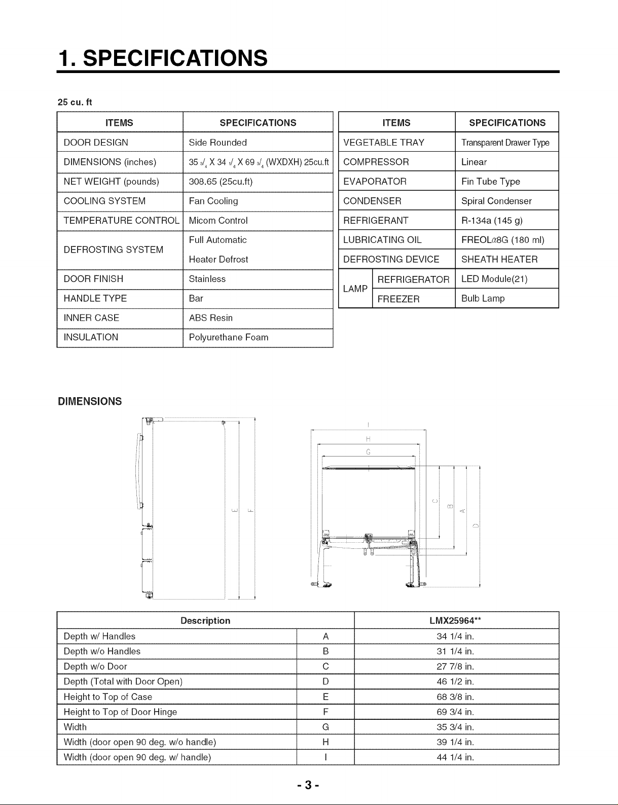
Description LMX25964**
Depth w/Handles A 34 1/4 in.
Depth w/o Handles B 31 1/4 in.
Depth w/o Door C 27 7/8 in.
Depth (Total with Door Open) D 46 1/2 in.
Height to Top of Case E 68 3/8 in.
Height to Top of Door Hinge F 69 3/4 in.
Width G 35 3/4 in.
Width (door open 90 deg. w/o handle) H 39 1/4 in.
Width (door open 90 deg. w/handle) I 44 1/4 in.
-3-
Page 4
2. PARTS IDENTIFICATION
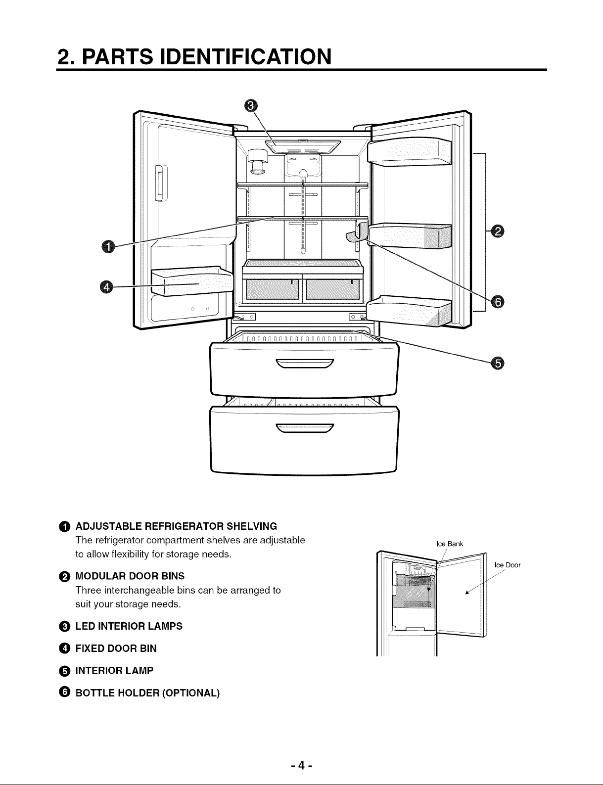
_) ADJUSTABLE REFRIGERATOR SHELVING
The refrigerator compartment shelves are adjustable
to allow flexibility for storage needs.
MODULAR DOOR BINS
O
Three interchangeable bins can be arranged to
suit your storage needs.
_) LED INTERIOR LAMPS
_) FIXED DOOR BIN
O INTERIOR LAMP
BOTTLE HOLDER (OPTIONAL)
Ice Bank
Ice Door
J
-4-
Page 5
3. DISASSEMBLY
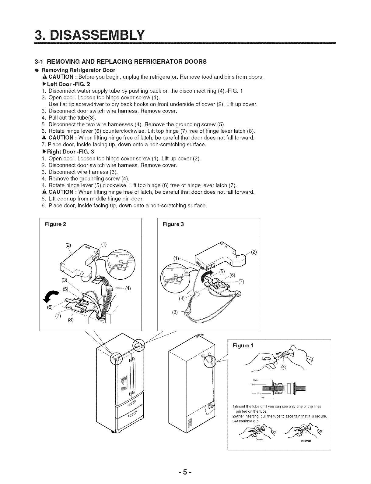
3=1 REMOVING AND REPLACING REFRIGERATOR DOORS
• Removing Refrigerator Door
-& CAUTION : Before you begin, unplug the refrigerator. Remove food and bins from doors.
1_Left Door -FIG. 2
1. Disconnect water supply tube by pushing back on the disconnect ring (4).-FIG. 1
2. Open door. Loosen top hinge cover screw (1).
Use flat tip screwdriver to pry back hooks on front underside of cover (2). Lift up cover.
3. Disconnect door switch wire harness. Remove cover.
4. Pull out the tube(3).
5. Disconnect the two wire harnesses (4). Remove the grounding screw (5).
6. Rotate hinge lever (6) counterclockwise. Lift top hinge (7) free of hinge lever latch (8).
_, CAUTION : When lifting hinge free of latch, be careful that door does not fall forward.
7. Place door, inside facing up, down onto a non-scratching surface.
Right Door -FIG. 3
1. Open door. Loosen top hinge cover screw (1). Lift up cover (2).
2. Disconnect door switch wire harness. Remove cover.
3. Disconnect wire harness (3).
4. Remove the grounding screw (4).
4. Rotate hinge lever (5) clockwise. Lift top hinge (6) free of hinge lever latch (7).
_, CAUTION : When lifting hinge free of latch, be careful that door does not fall forward.
5. Lift door up from middle hinge pin door.
6. Place door, inside facing up, down onto a non-scratching surface.
Figure 2
J
(7) /
(3).
(2)
(8)
_(1)
Figure 3
(1)_
/
/
(3)_-4_
(2)
Figure 1
-5-
1)Insert the tube until you can see only one of the lines
printed on the tube.
2)After inserting, pull the tube to ascertain that it is secure.
3)Assemble clip.
Incorr_ct
Page 6
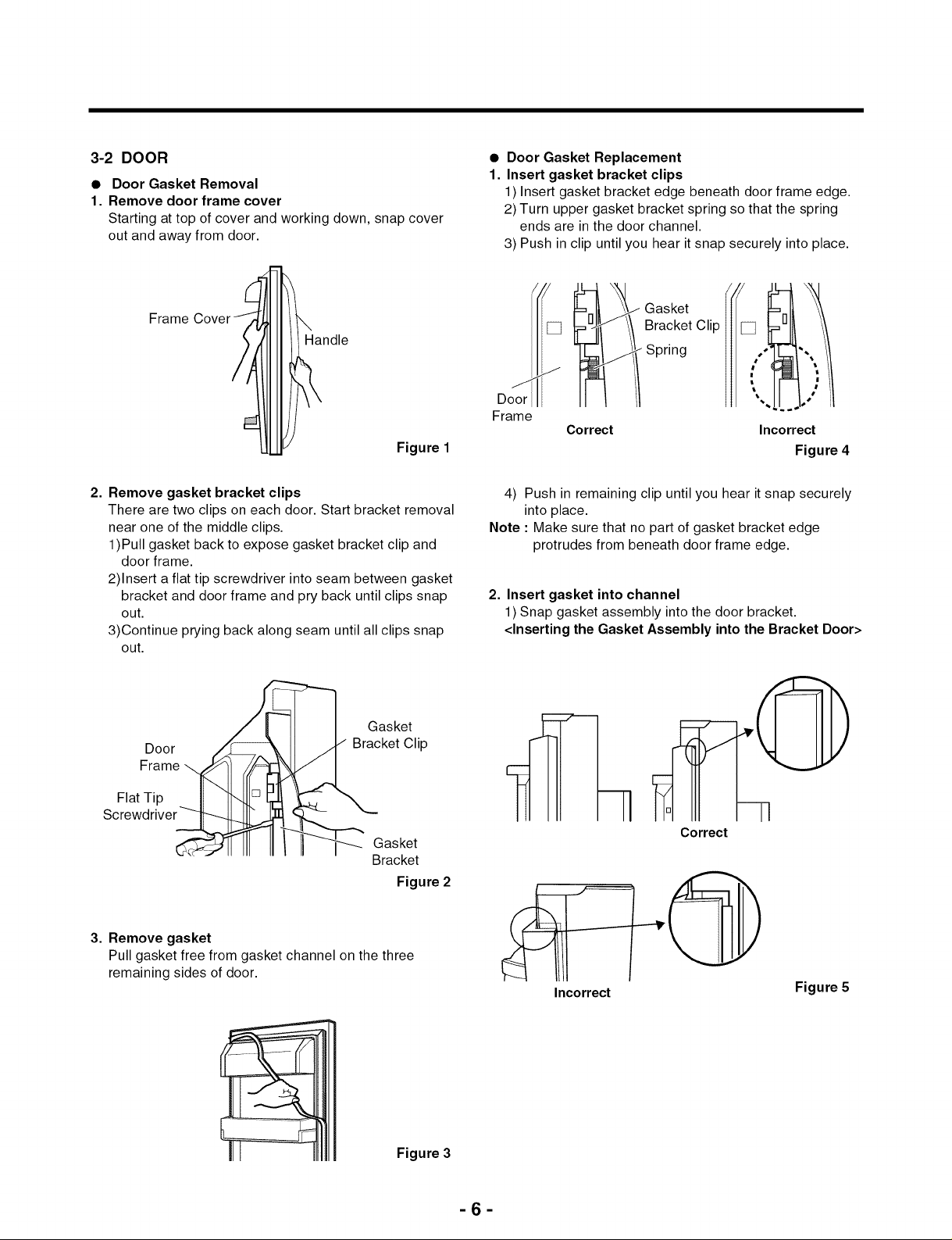
3-2 DOOR
• Door Gasket Removal
1. Remove door frame cover
Starting at top of cover and working down, snap cover
out and away from door.
Frame
Figure 1
• Door Gasket Replacement
1. Insert gasket bracket clips
1) Insert gasket bracket edge beneath door frame edge.
2) Turn upper gasket bracket spring so that the spring
ends are in the door channel.
3) Push in clip until you hear it snap securely into place.
Bracket Clip [] .
Spring
/I, il
Door -..
Frame
Correct Incorrect
Figure 4
2. Remove gasket bracket clips
There are two clips on each door. Start bracket removal
near one of the middle clips.
1)Pull gasket back to expose gasket bracket clip and
door frame.
2)Insert a flat tip screwdriver into seam between gasket
bracket and door frame and pry back until clips snap
out.
3)Continue prying back along seam until all clips snap
out.
__] Gasket
Door /_ II ,_ Bracket Clip
Frame ,_ ___"L
Flat Tip _ II \
Screwd river___l.. _..T_.._-"
Jll III Ill II W Gasket
3. Remove gasket
Pull gasket free from gasket channel on the three
remaining sides of door.
Bracket
Figure 2
4) Push in remaining clip until you hear it snap securely
into place.
Note : Make sure that no part of gasket bracket edge
protrudes from beneath door frame edge.
2. Insert gasket into channel
1) Snap gasket assembly into the door bracket.
<Inserting the Gasket Assembly into the Bracket Door>
Correct
Incorrect
Figure 5
Figure 3
6
Page 7
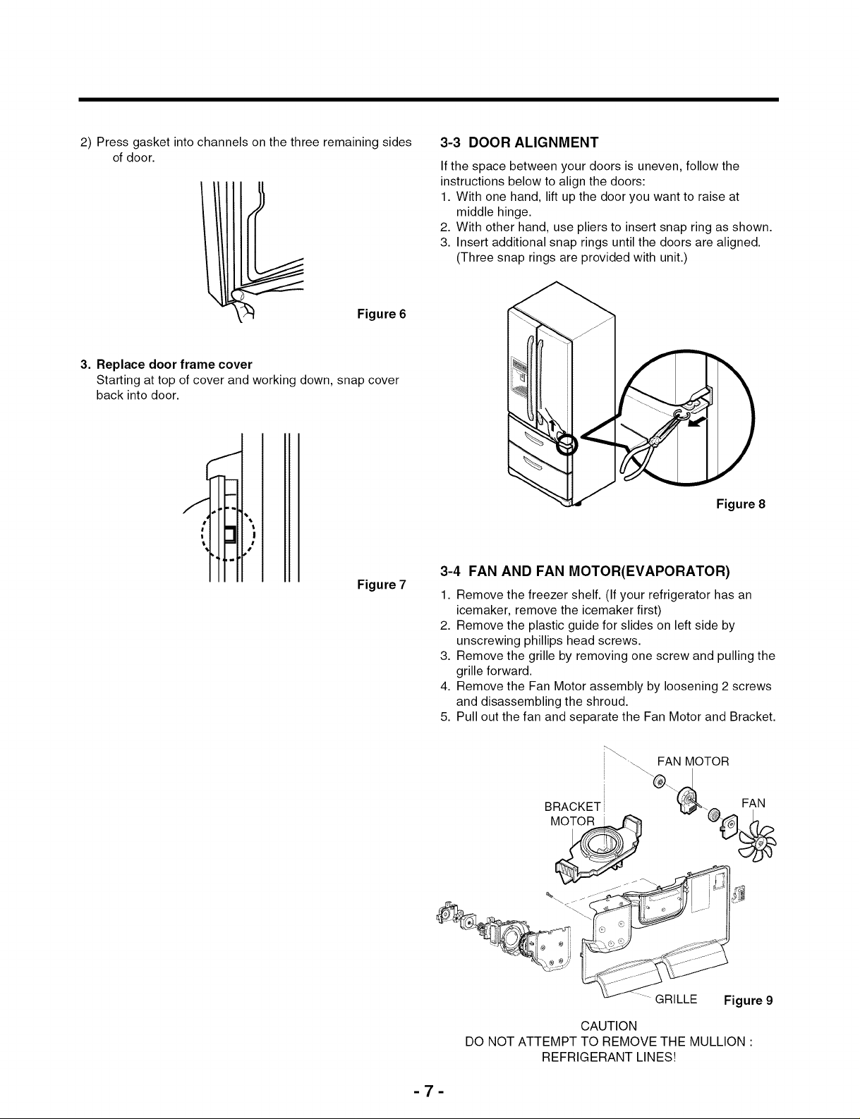
2) Press gasket into channels on the three remaining sides
of door.
Figure 6
3. Replace door frame cover
Starting at top of cover and working down, snap cover
back into door.
3-3 DOOR ALIGNMENT
If the space between your doors is uneven, follow the
instructions below to align the doors:
1. With one hand, lift up the door you want to raise at
middle hinge.
2. With other hand, use pliers to insert snap ring as shown.
3. Insert additional snap rings until the doors are aligned.
(Three snap rings are provided with unit.)
t,,f,_,
!
ttFtt:
Figure 7
Figure 8
3-4 FAN AND FAN MOTOR(EVAPORATOR)
1. Remove the freezer shelf. (If your refrigerator has an
icemaker, remove the icemaker first)
2. Remove the plastic guide for slides on left side by
unscrewing phillips head screws.
3. Remove the grille by removing one screw and pulling the
grille forward.
4. Remove the Fan Motor assembly by loosening 2 screws
and disassembling the shroud.
5. Pull out the fan and separate the Fan Motor and Bracket.
_ FAN MOTOR
BRACKET
%\
-7-
GRILLE Figure 9
CAUTION
DO NOT ATTEMPT TO REMOVE THE MULLION •
REFRIGERANT LINES!
Page 8
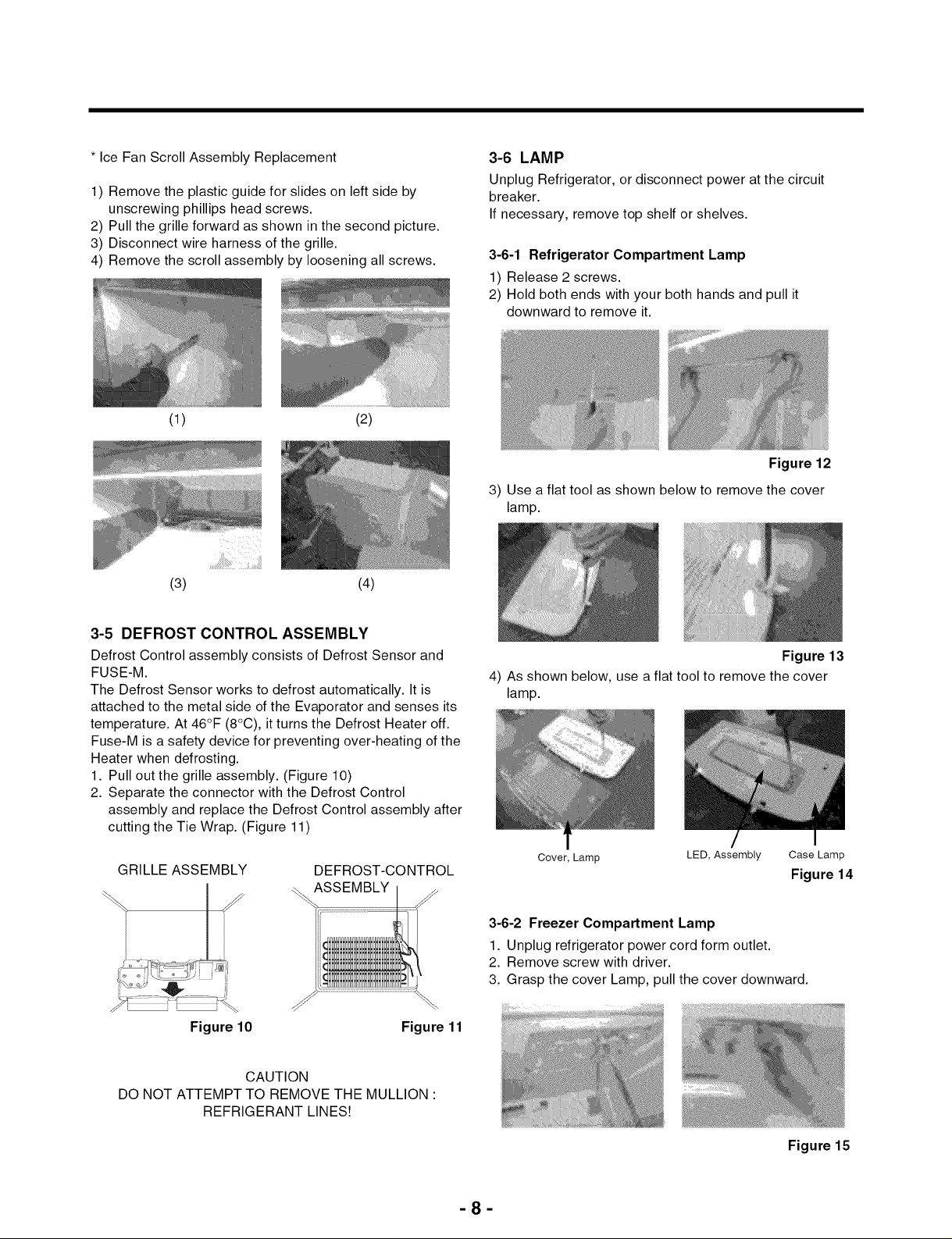
* Ice Fan Scroll Assembly Replacement
1) Remove the plastic guide for slides on left side by
unscrewing phillips head screws.
2) Pull the grille forward as shown in the second picture.
3) Disconnect wire harness of the grille.
4) Remove the scroll assembly by loosening all screws.
(1) (2)
(3) (4)
3-6 LAMP
Unplug Refrigerator, or disconnect power at the circuit
breaker.
If necessary, remove top shelf or shelves.
3-6-1 Refrigerator Compartment Lamp
1) Release 2 screws.
2) Hold both ends with your both hands and pull it
downward to remove it.
Figure 12
3) Use a flat tool as shown below to remove the cover
lamp.
3-5 DEFROST CONTROL ASSEMBLY
Defrost Control assembly consists of Defrost Sensor and
FUSE-M.
The Defrost Sensor works to defrost automatically. It is
attached to the metal side of the Evaporator and senses its
temperature. At 46°F (8°C), it turns the Defrost Heater off.
Fuse-M is a safety device for preventing over-heating of the
Heater when defrosting.
1. Pull out the grille assembly. (Figure 10)
2. Separate the connector with the Defrost Control
assembly and replace the Defrost Control assembly after
cutting the Tie Wrap. (Figure 11)
GRILLE ASSEMBLY
DEFROST-CONTROL
ASSEMBLY
Figure 10 Figure 11
CAUTION
DO NOT ATTEMPT TO REMOVE THE MULLION •
REFRIGERANT LINES!
Figure 13
4) As shown below, use a flat tool to remove the cover
lamp.
Cover, Lamp LED, Assembly Case Lamp
Figure 14
3-6-2 Freezer Compartment Lamp
1. Unplug refrigerator power cord form outlet.
2. Remove screw with driver.
3. Grasp the cover Lamp, pull the cover downward.
-8-
Figure 15
Page 9
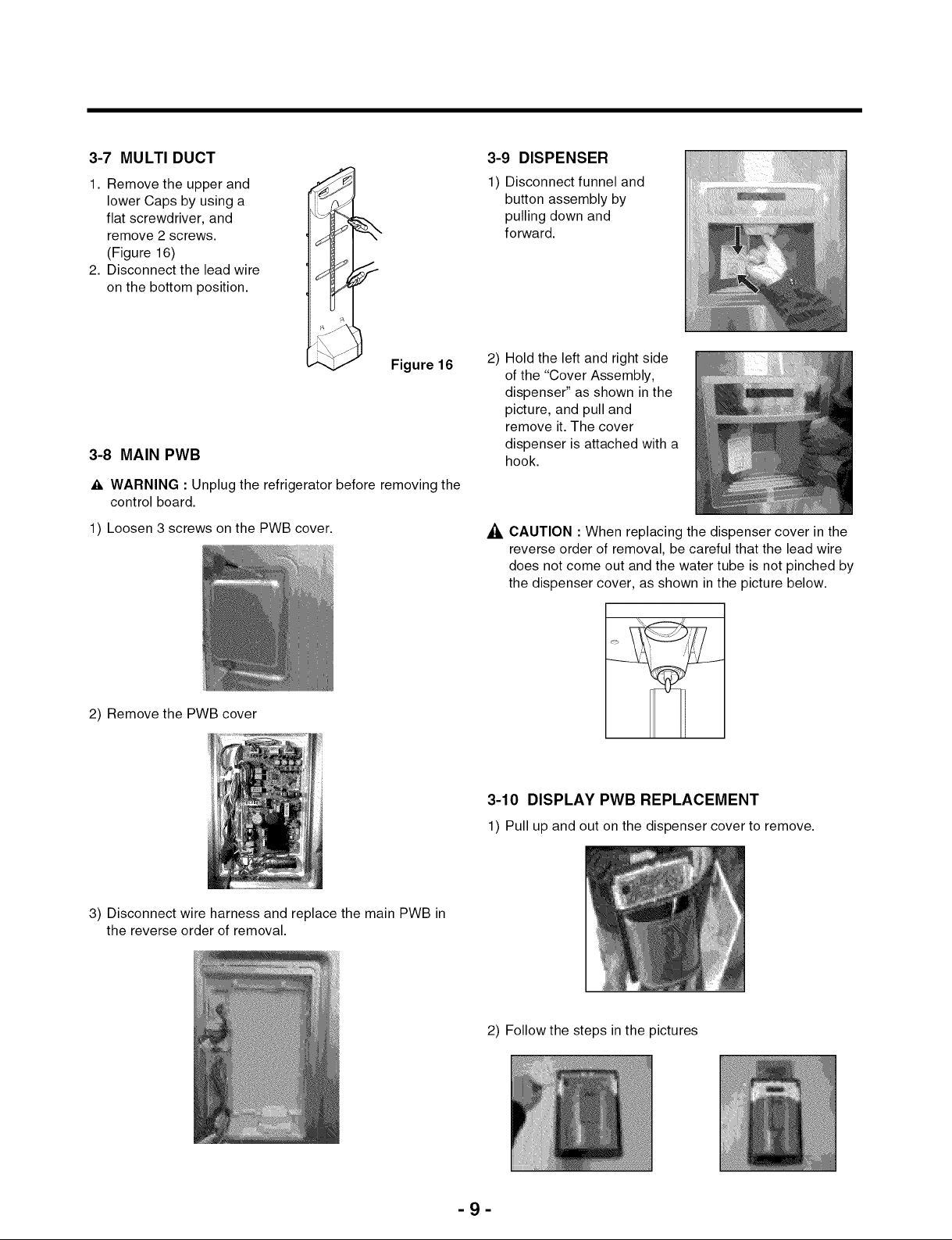
3-7 MULTI DUCT
1. Remove the upper and
lower Caps by using a
flat screwdriver, and
remove 2 screws.
(Figure 16)
2. Disconnect the lead wire
on the bottom position.
3-9 DISPENSER
1) Disconnect funnel and
button assembly by
pulling down and
forward.
Figure 16
3-8 MAIN PWB
_k WARNING : Unplug the refrigerator before removing the
control board.
1) Loosen 3 screws on the PWB cover.
2) Remove the PWB cover
2) Hold the left and right side
of the "Cover Assembly,
dispenser" as shown inthe
picture, and pull and
remove it. The cover
dispenser is attached with a
hook.
CAUTION : When replacing the dispenser cover in the
reverse order of removal, be careful that the lead wire
does not come out and the water tube is not pinched by
the dispenser cover, as shown in the picture below.
3-10 DISPLAY PWB REPLACEMENT
3) Disconnect wire harness and replace the main PWB in
the reverse order of removal.
1) Pull up and out on the dispenser cover to remove.
2) Follow the steps in the pictures
-9-
Page 10
3-11 FUNNEL REPLACEMENT
1) Pull up and out on the dispenser cover to remove.
2) Disconnect the wire harness.
3) Replace in reverse order.
3-12 SUB PWB FOR WORKING DISPENSER
1) Loosen the screw on the sub PWB.
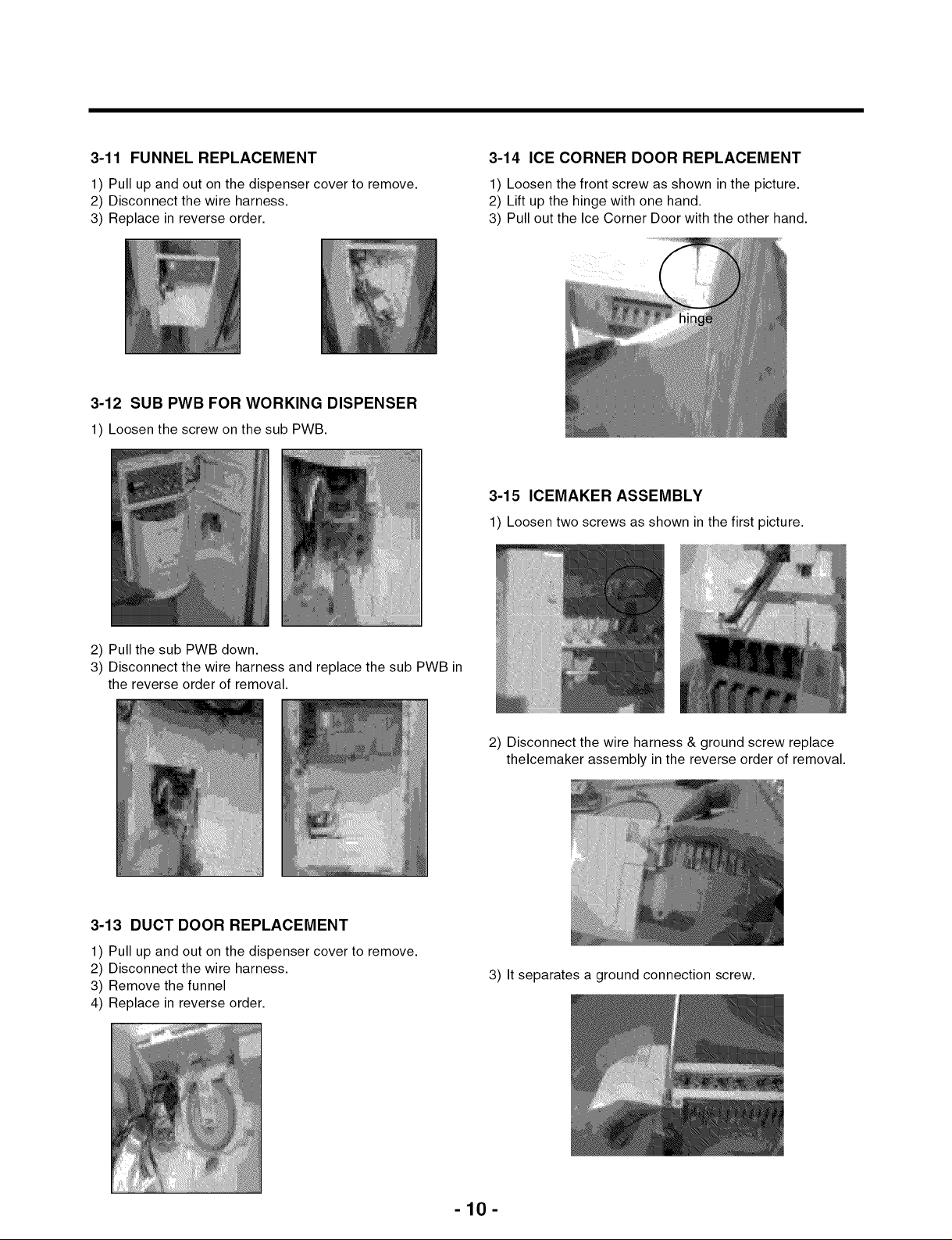
3-14 ICE CORNER DOOR REPLACEMENT
1) Loosen the front screw as shown in the picture.
2) Lift up the hinge with one hand.
3) Pull out the Ice Corner Door with the other hand.
3-15 ICEMAKER ASSEMBLY
1) Loosen twoscrews as shown in the first picture.
2) Pull the sub PWB down.
3) Disconnect the wire harness and replace the sub PWB in
the reverse order of removal.
3-13 DUCT DOOR REPLACEMENT
1) Pull up and out on the dispenser cover to remove.
2) Disconnect the wire harness.
3) Remove the funnel
4) Replace in reverse order.
2) Disconnect the wire harness & ground screw replace
thelcemaker assembly in the reverse order of removal.
3) It separates a ground connection screw.
-10-
Page 11
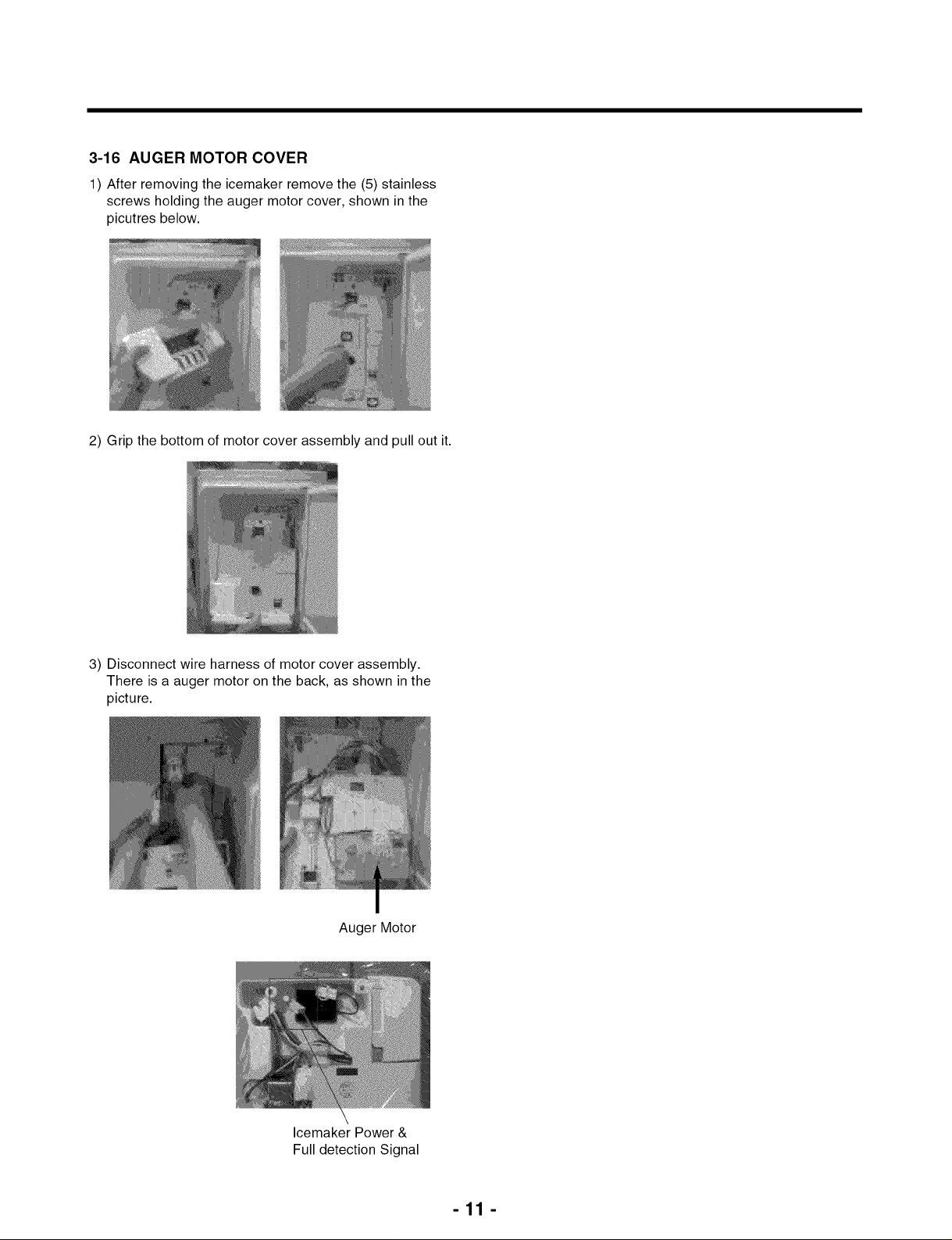
3-16 AUGER MOTOR COVER
1) After removing the icemaker remove the (5) stainless
screws holding the auger motor cover, shown in the
picutres below.
2) Grip the bottom of motor cover assembly and pull out it.
3) Disconnect wire harness of motor cover assembly.
There is a auger motor on the back, as shown in the
picture.
Auger Motor
Icemaker Power &
Full detection Signal
-11 -
Page 12
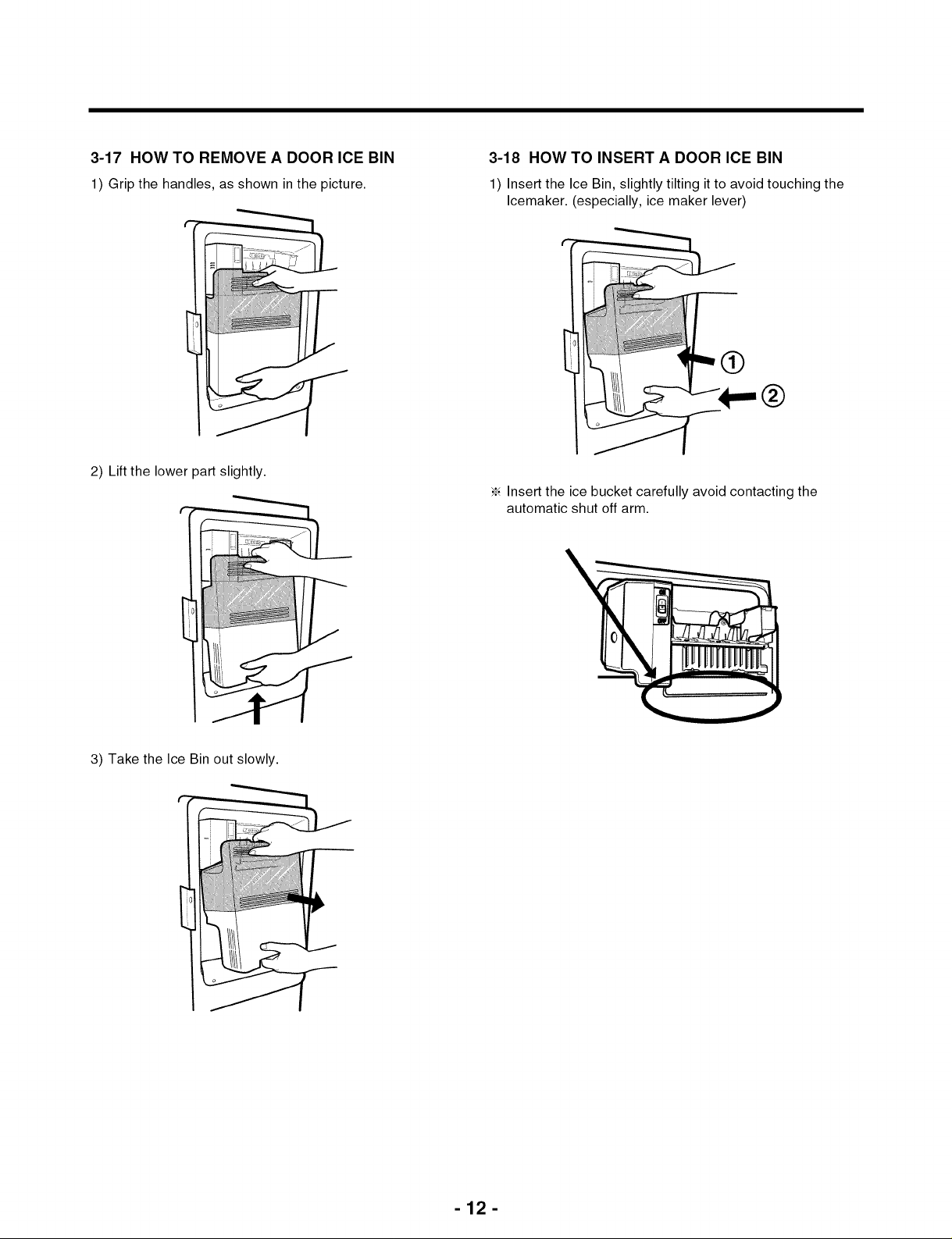
3-17 HOW TO REMOVE A DOOR ICE BIN
1) Grip the handles, as shown in the picture.
2) Lift the lower part slightly.
3-18 HOW TO INSERT A DOOR ICE BIN
1) Insert the Ice Bin, slightly tilting it to avoid touching the
Icemaker. (especially, ice maker lever)
•_ Insert the ice bucket carefully avoid contacting the
automatic shut off arm.
3) Take the Ice Bin out slowly.
-12-
Page 13
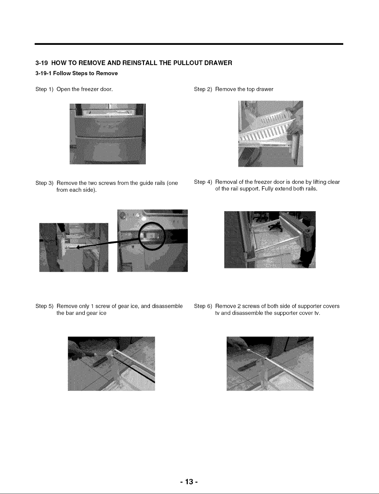
3-19 HOW TO REMOVE AND REINSTALL THE PULLOUT DRAWER
3-19-1 Follow Steps to Remove
Step 1) Open the freezer door. Step 2) Remove the top drawer
Step 3) Remove the two screws from the guide rails (one
from each side).
Step 5) Remove only 1 screw of gear ice, and disassemble
the bar and gear ice
Step 4) Removal of the freezer door is done by lifting clear
of the rail support. Fully extend both rails.
Step 6) Remove 2 screws of both side of supporter covers
tv and disassemble the supporter cover tv.
-13-
Page 14
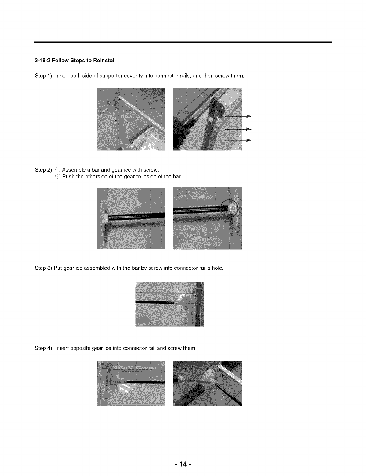
3-19-2 Follow Steps to Reinstall
Step 1) Insert both side of supporter cover tv into connector rails, and then screw them.
Step 2) (_ Assemble a bar and gear ice with screw.
2_ Push the otherside of the gear to inside of the bar.
Step 3) Put gear ice assembled with the bar by screw into connector rail's hole.
Step 4) Insert opposite gear ice into connector rail and screw them
-14-
Page 15
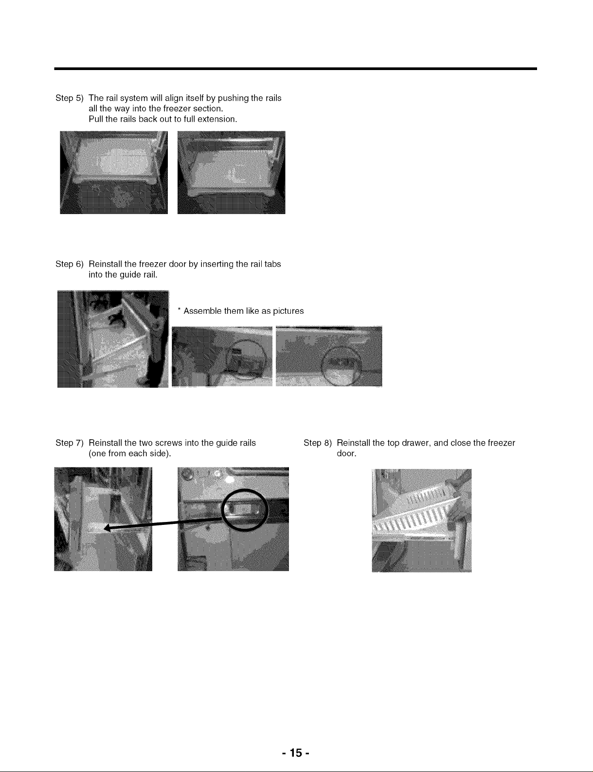
Step 5) The rail system will align itself by pushing the rails
all the way into the freezer section.
Pull the rails back out to full extension.
Step 6) Reinstall the freezer door by inserting the rail tabs
into the guide rail.
* Assemble them like as pictures
Step 7) Reinstall the two screws into the guide rails
(one from each side).
Step 8) Reinstall the top drawer, and close the freezer
door.
-15-
Page 16
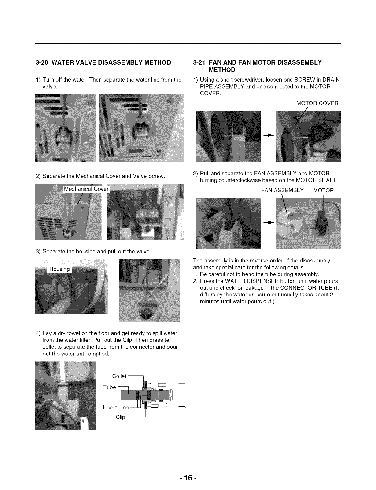
3-20 WATER VALVE DISASSEMBLY METHOD
1 Turn off the water. Then separate the water line from the
valve.
3-21 FAN AND FAN MOTOR DISASSEMBLY
METHOD
1) Using a short screwdriver, loosen one SCREW in DRAIN
PIPE ASSEMBLY and one connected to the MOTOR
COVER.
MOTOR COVER
2) Separate the Mechanical Cover and Valve Screw.
3) Separate the housing and pull out the valve.
Housing
4) Lay a dry towel on the floor and get ready to spill water
from the water filter. Pull out the Cilp. Then press te
collet to separate the tube from the connector and pour
out the water until emptied.
2) Pull and separate the FAN ASSEMBLY and MOTOR
turning counterclockwise based on the MOTOR SHAFT.
FAN ASSEMBLY MOTOR
The assembly is in the reverse order of the disassembly
and take special care for the following details.
1. Be careful not to bend the tube during assembly.
2. Press the WATER DISPENSER button until water pours
out and check for leakage in the CONNECTOR TUBE (It
differs by the water pressure but usually takes about 2
minutes until water pours out.)
Collet --
Tube --
Insert Line
Clip --
-16-
Page 17
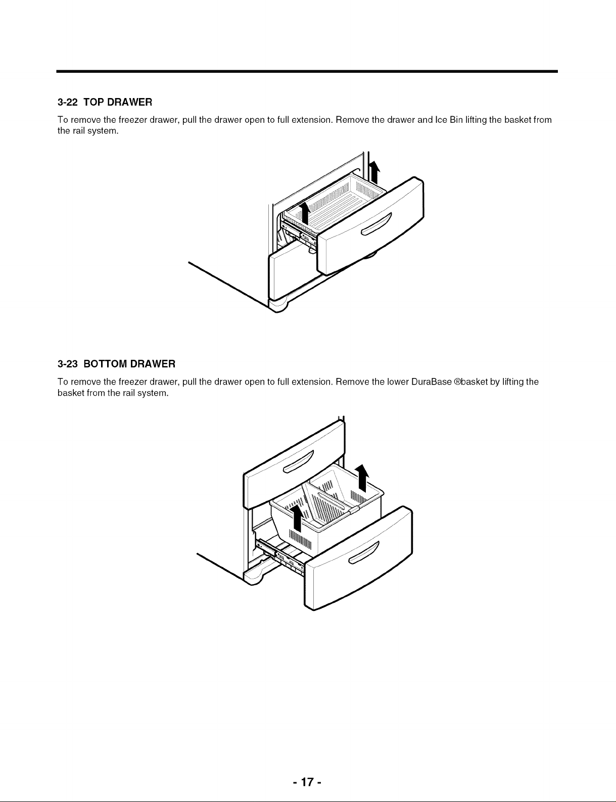
3-22 TOP DRAWER
To remove the freezer drawer, pull the drawer open to full extension. Remove the drawer and Ice Bin lifting the basket from
the rail system.
3-23 BOTTOM DRAWER
To remove the freezer drawer, pull the drawer open to full extension. Remove the lower DuraBase @basket by lifting the
basket from the rail system.
-17-
Page 18
4. ADJUSTMENT
4-1 COMPRESSOR
4-1-1 Role
The compressor intakes low temperature and low pressure
gas from the evaporator of the refrigerator and compresses
this gas to high-temperature and high-pressure gas. It then
delivers the gas to the condenser.
4-1-2 Note for Usage
(1) Be careful not to allow over-voltage and over-current.
(2) Do not drop or handle carelessly.
(3) Keep away from any liquid.
If liquid such as oil or water enters the Cover PTC
Compressor may fail due to breakdown of their
insulating capabilities.
(4) Always use the Parts designed for the compressor and
make sure it is properly attached to the compressor.
Parts may appear physically identical but could have
different electrical ratings. Replace parts by part number
and model number. Use only approved substitute parts.
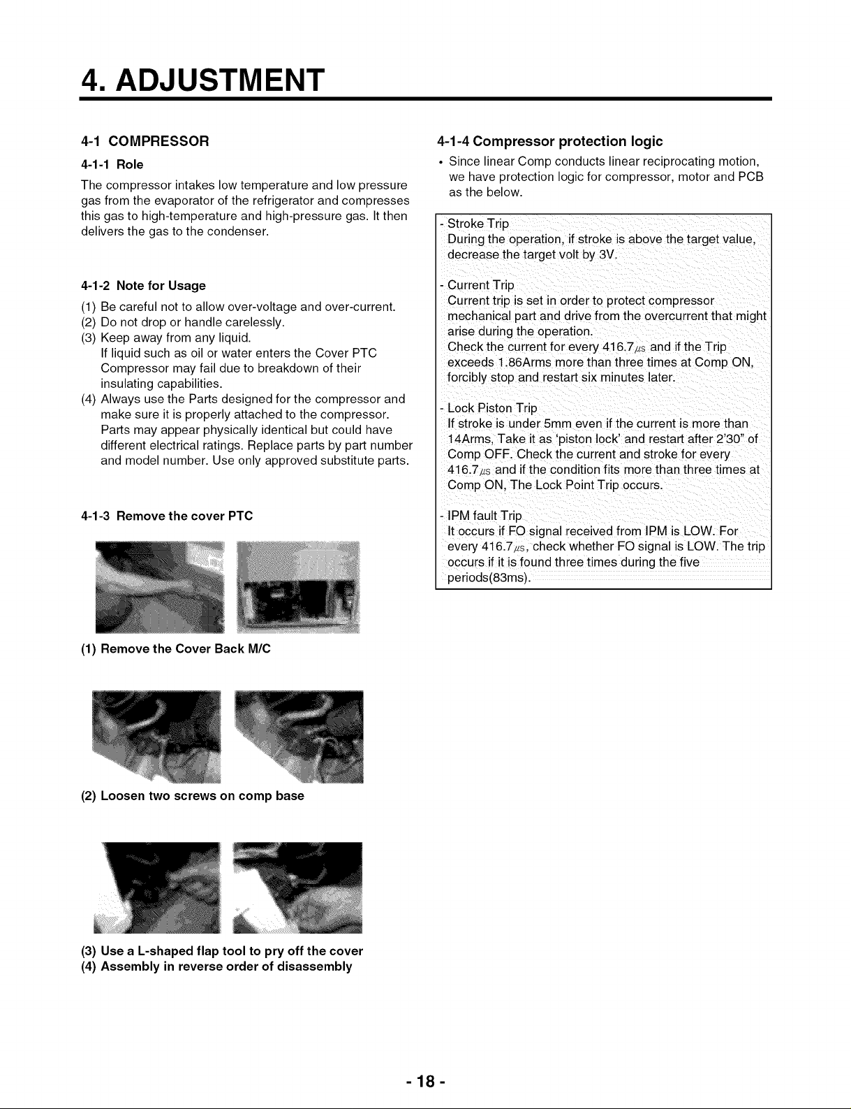
4-1-3 Remove the cover PTC
4-1-4 Compressor protection logic
• Since linear Comp conducts linear reciprocating motion,
we have protection logic for compressor, motor and PCB
as the below.
- Stroke Trip
During the operation, if stroke is above the target vaJue,
decrease the target volt by 3V.
- Current Trip
Current trip is set in order to protect compressor
mechanical part and drive from the overcu rrent that might
arise during the operation.
Check the current for every 416.7,s and if the Trip
exceeds 1.86Arms more than three times at Comp ON,
forcibly stop and restart six minutes later.
- Lock Piston Trip
If stroke is under 5mm even if the current is more than
14Arms, Take it as 'piston lock' and restart after 2'30" of
Comp OFF. Check the current and stroke for every
416.7,s and if the condition fits more than three times at
Comp ON, The Lock Point Trip occurs.
- IPM fault Trip
It occurs if FO signal received from IPM is LOW. For
every 416.7_s, check whether FO signal is LOW. The trip
occurs if it is found three times during the five
periods(83ms).
(1) Remove the Cover Back M/C
(2) Loosen two screws on comp base
(3) Use a L-shapedflap tool to pry off the cover
(4) Assembly in reverse order of disassembly
-18-
Page 19
01
0
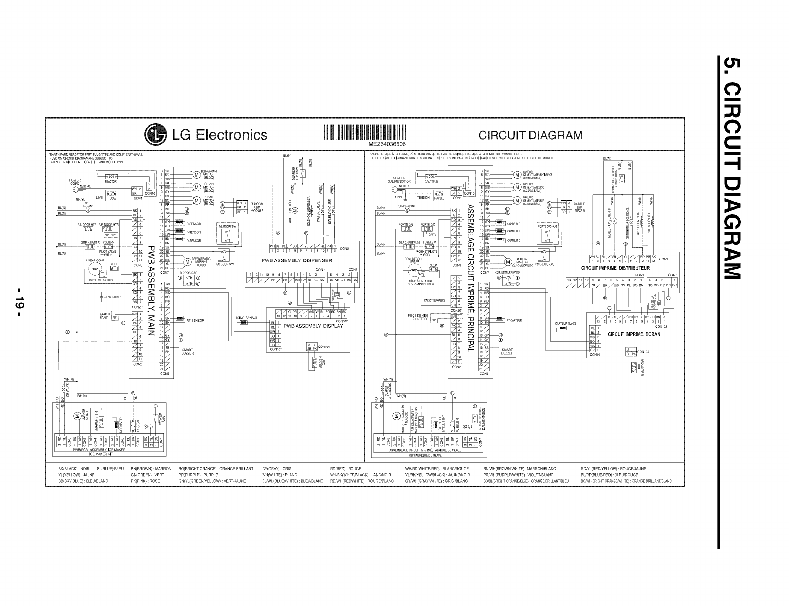
LG Electronics IIIIlllllllllllIIIIIIll C_RCUUTD_AGRAM
MEZ64036506
*pIECE DE M_E A LA TERRE REACTEIJR _ARTI E WP DE PRISE ET OE MIS A _ TERRE DU CO_pRESSEUR
]
0
C
-!
Q
I
€0
I
_W(N)
ICEMAKERKI-
BK(BLACK):NOIR B_(BLUE):BLEU BN(BROWN): MARRON BO(BRIG_TORANGE): ORANGEBRILLANT GY(GRAY):GRIS RD(RED): ROUGE WH/RD(W_ITE/RED): BLANC/ROUGE BNtWH(BROWN/WHITE}: MARRON/BLANC R_YL(RED/YELLOW): ROUGE_AUNE
YL(YELLOW):JAUNE GN(GREEN}: VERT PR(PURPLE):PURPLE WH(WHITE):BLANC WH/BK(WHITE!BLACK):LANC!NOIR YUBK(YELLOW/BLACK}:JAUNE/NOIR P_WH(PURPLE_HITE): VlOLE_BLANC BL/RD(BLUEiRED}:BLEU!ROUGE
SB(SKYBLUE): BLEU/BLANC PK(PINK): ROSE GN/YL(GREEN/YELLOW): VERT!JAUNE BL_H(BLUE_HITE) : BLEU/BLANC RDANH(RED_HITE):ROUGE/BLANC GY/W_(GRAY/WHITE): GRIS/BLANC BOIBL(BRIGHTO_NG_LUE} :ORANGEBRILLAN_BLEU BOeVH(BRIGHTORAN6E_HITE):ORANGEBRILLANT_BLANC
Page 20
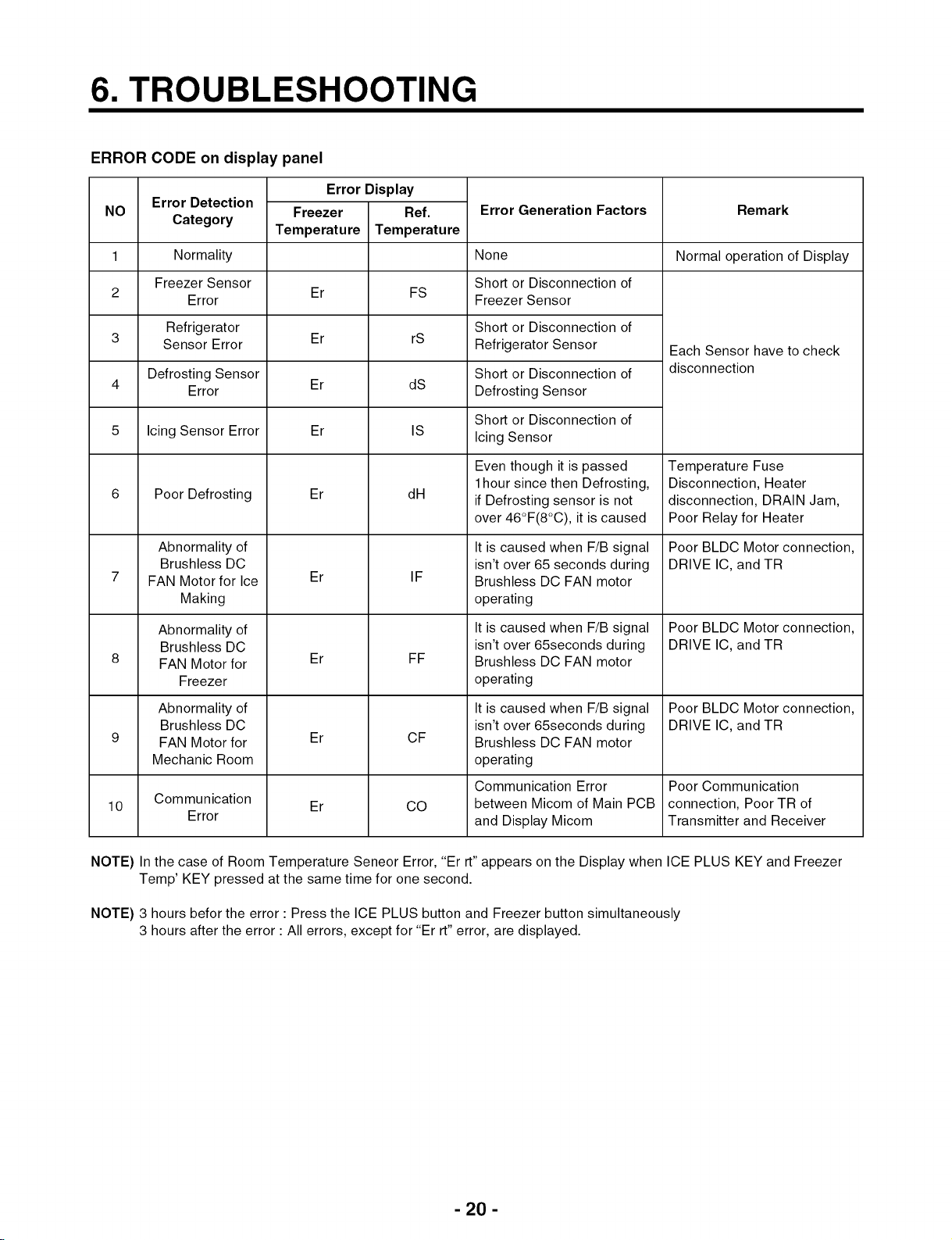
6. TROUBLESHOOTING
ERROR CODE on display panel
Error Detection
NO
1
2
3 Er rS Refrigerator Sensor
4 Er dS Defrosting Sensor
5 Icing Sensor Error Er IS
Category
Normality
Freezer Sensor
Error
Refrigerator
Sensor Error
Defrosting Sensor
Error
Poor Defrosting
Abnormality of
Brushless DC
FAN Motor for Ice
Making
Abnormality of
Brushless DC
FAN Motor for
Freezer
Temperature
Error Display
Freezer
Temperature
Er FS
Er
Er
Er
Ref.
dH
IF
FF
Error Generation Factors Remark
None Normal operation of Display
Short or Disconnection of
Freezer Sensor
Short or Disconnection of
Short or Disconnection of
Short or Disconnection of
Icing Sensor
Even though it is passed
1hour since then Defrosting,
if Defrosting sensor is not
over 46°F(8°C), it is caused
It is caused when F/B signal
isn't over 65 seconds during
Brushless DC FAN motor
operating
It is caused when F/B signal
isn't over 65seconds during
Brushless DC FAN motor
operating
Each Sensor have to check
disconnection
Temperature Fuse
Disconnection, Heater
disconnection, DRAIN Jam,
Poor Relay for Heater
Poor BLDC Motor connection,
DRIVE IC, and TR
Poor BLDC Motor connection,
DRIVE IC, and TR
Abnormality of
Brushless DC
FAN Motor for
Mechanic Room
Communication
10
NOTE) In the case of Room Temperature Seneor Error, "Er rt" appears on the Display when ICE PLUS KEY and Freezer
Temp' KEY pressed at the same time for one second.
NOTE) 3 hours befor the error : Press the ICE PLUS button and Freezer button simultaneously
3 hours after the error : All errors, except for "Er rt" error, are displayed.
Error
Er
Er
CF
CO
It is caused when F/B signal
isn't over 65seconds during
Brushless DC FAN motor
operating
Communication Error
between Micom of Main PCB
and Display Micom
Poor BLDC Motor connection,
DRIVE IC, and TR
Poor Communication
connection, Poor TR of
Transmitter and Receiver
- 20 -
Page 21
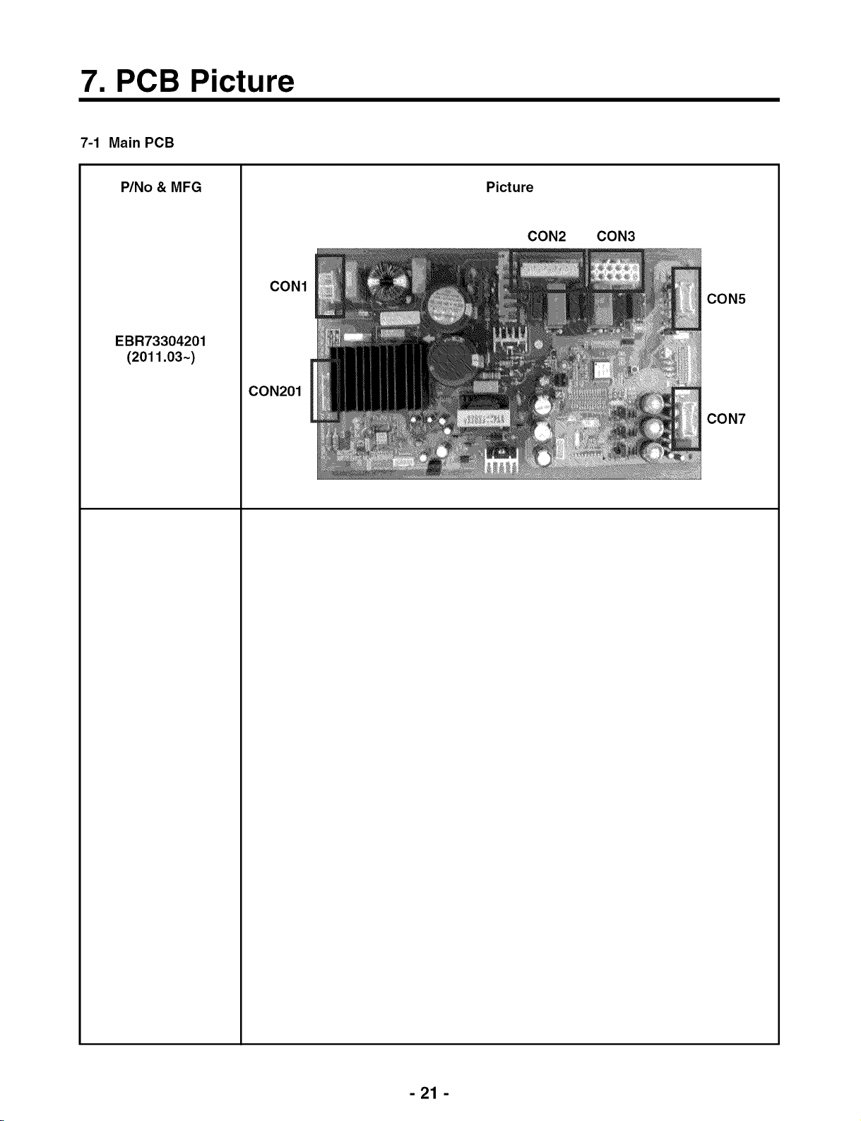
7. PCB Picture
7-1 Main PCB
P/No & MFG
EBR73304201
(2011.03~)
Picture
CON2 CON3
CON1
CON5
CON201
CON7
-21 -
Page 22
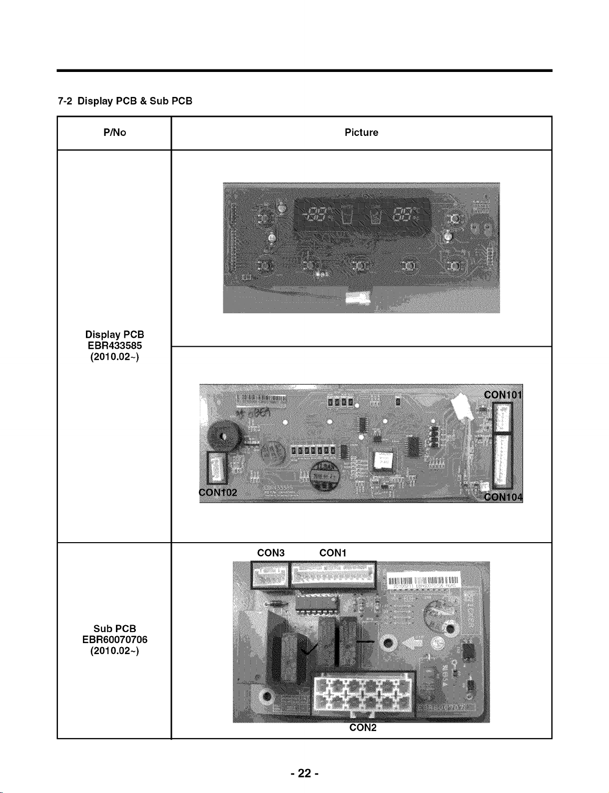
7-2 Display PCB & Sub PCB
P/No Picture
Display PCB
EBR433585
(2010.02~)
Sub PCB
EBR60070706
(2010.02~)
CON3 CON1
CON2
- 22 -
Page 23
8. Troubleshootin laWith Error Dis
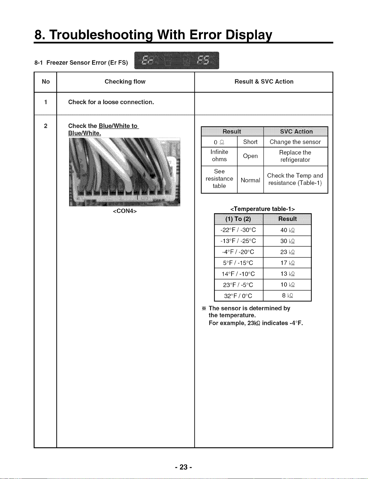
84 Freezer Sensor Error (Er FS)
No Checking flow Result & SVC Action
1 Check for a loose connection.
2 Check the Blue/White to
Blue/White.
iiiiiiiiiiiiiiiiiiiiiiiiiiiiiiiiiiiiiiiiiiiiiiiiiiiiiiiiiiiiiiiiiiiiiiiiiiiiiiiiiiiiiiii_i_;!_;!_i_!!_i_!iii_!_i!_i!_i!_i!_i!_i!_i!_i!_i!_i!_i!_i!_i!_i!_i!_i!_i!_i!_i!_i!_i!_i!_i!_i!_i!_i!_i!_i!_i!_i!_i!_i!_i!_i!_i!_i!_i!_i!_i!_i!_i!_i!_i!_!_i!_!_!iiiiiiiiiiiiiiiiiiiiiiiiiiiiiiiiiiiiiiiiiiiiiiiiiiiiiiiiiiiiiiiiii_i_i!_!_i!_i!_i!_!_!i_i!_!_i_i_i_i_i_i_i_i_i_i_i_i_i_i_i_i_i_i_i_i_i_i_i_i_i_i_i_i_i_i_i_i_i_i_
0 S Short Change the sensor
Infinite Replace the
ohms Open refrigerator
<CON4>
See
resistance Normal resistance (Table-I)
table
<Temperature table-l>
-22°F / -30°C 40 k_
-13°F / -25°C 30 k_
-4°F / -20°C 23 k_
5°F/-15°C 17 k_
14°F/-10°C 13 k_
23°F / -5°C 10 k_
32OF/ OoC 8 k_
The sensor is determined by
the temperature.
For example, 23k£ indicates =4°F.
Check the Temp and
- 23 -
Page 24
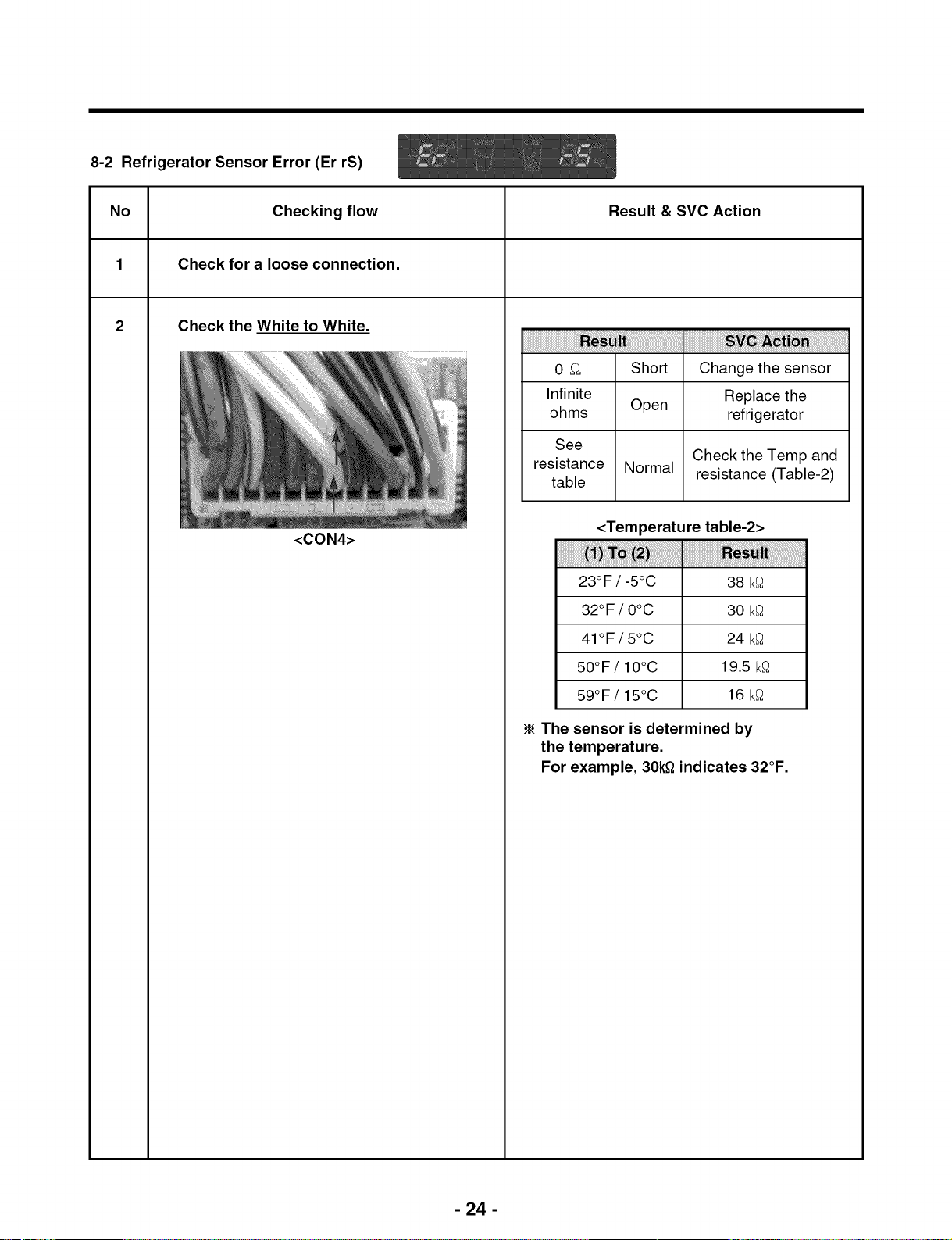
8-2 Refrigerator Sensor Error (Er rS)
No Checking flow Result & SVC Action
1 Check for a loose connection.
2 Check the White to White.
0 _ Short Change the sensor
Infinite Replace the
ohms Open refrigerator
<CON4>
See
resistance Normal resistance (Table-2)
table
<Temperature table-2>
23°F / -5°C 38 k_
32°F / O°C 30 k_
41°F / 5°C 24 k_
50°F/10°C 19.5 k_
59°F/15°C 16 k_
The sensor is determined by
the temperature.
For example, 30k£ indicates 32°F.
Check the Temp and
- 24 -
Page 25

8-3 Icing Sensor Error (Er IS)
No Checking flow Result & SVC Action
1 Check for a loose connection.
2 Check the Blue to Blue.
<Display>
<CON101>
1>
0 _ Short Change the sensor
Check the resistance
of the defrost sensor
wires back to the
main PCB. If they are
Infinite Open open between the
ohms Main PCB and the
connector for the
icemaker it will be
necessary to replace
the refrigerator.
See
Check the Temp and
resistance Normal resistance (Table-I)
table
<Temperature table-l>
-22°F / -30°C 40 k_
-13°F / -25°C 30 k_
-4°F / -20°C 23 k_
- 25 -
5°F/-15°C 17 k_
14°F/-10°C 13 k_
23OF/ -5oc 10 k_
32OF/ OoC 8 k_
The sensor is determined by
the temperature.
For example, 23k£ indicates -4°F.
Page 26

8-4 Defrost Sensor Error (F dS)
No Checking flow Result & SVC Action
1 Check for a loose connection.
2
Check the Orange to Orange.
iiiiiiiiiiiiiiiiiiiiiiiiiiiiiiiiiiiiiiiiiiiiiiiiiiiiiiiiiiiiiiiiiiiiiiiiiiiiiiiiiiiiiiiiiiiiiii i i ! ! l i i i i i i i i i i i i i i i i i i i i i i i i i i i i i i i i i i i i i i i i i i i i i i iiiiiiiiiiiiiiiiiiiiiiiiiiiiiiiiiiiiiiiiiiiiiiiiiiiiiiiiiiiiiiiiii i ;! ! ! ! ! i i ii i i ! i! i! i! i! i! i! i! i! i! i! i! i! i! i! i! i! i! i! i! i! i! i! i! i! i! !i !i !i !i !ii i
0 _ Short Change the sensor
Infinite Replace the
ohms Open refrigerator
Check the Brown to Brown.
<CON4>
See
resistance Normal resistance (Table-3)
table
<Temperature table-3>
-22°F / -30°C 40 k_
-13°F / -25°C 30 k_
-4°F / -20°C 23 k_
5°F/-15°C 17 k_
14°F/-10°C 13 k_
23°F / -5°C 10 k_
32OF/ OoC 8 k_
Check the Temp and
- 26 -
The sensor is determined by
the temperature.
For example, 23k£ indicates -4°F.
Page 27

8-5 Defrost Heater Error (Er dH)
No Checking flow Result & SVC Action
1 Check the Door gasket.
2
Check the Defrost control part.
Defrost Heater
Fuse-M
Defrost 34~42 _ Goto the 3
Heater Other Change Fuse-M
Defrost
Sensor
0_
Other Change Fuse-M
0 _ Go to the 3
Check the resistance of
the defrost sensor wires
back to the main PCB.
Infinite
ohms
between the Main PCB
and the connector for
the icemaker it will be
necessary to replace
Go to the 3
If they are open
the refrigerator.
3
4
5
6
Input Test 3 Mode.
(Push the button 3 times)
Check the Blue(Pin4) to Orange(PinD) at
CON3 on the main PCB
112 ~ 116V Go to the 5
0 V Replace Main PCB
<CON3>
Release the test mode.
Push the button 1 times. (Normal)
Check the Blue(Pin4) to Orange(PinD) at
CON3 on the main PCB
<CON3>
0 V Normal
112 ~ 116 V Replace Main PCB
- 27 -
Page 28

8-6 Freezer Fan Error (Er FF)
Checking flow
Reset the unit and
Input Test I Mode.
(Push the button 1 time)
Open the freezer door and Check the air
flow.
While an error code is displayed,
the fan is not working.
Check the Fan motor.
Result & SVC Action
!i!i!i!i!i!i!i!i!iiiiiiiiii ! ii ii ilililililililililiiiii !i ii i!,i!i!i!i!iiii ii'il
No airflow Go to 3
Airflow Go to 4
Rotate fan using your hand.
It feel stuck or locked up, change the motor.
(Cause of ice or rust inside of motor)
(1)Pin8, (2)Pin10, (3)Pin12
<CON7>
iiiiiiiiiiiiiiiiiiiiiiiiii ! ! ii ii ! {i i i i i i i i i i i i i i
(1) ~ (2)
(2) ~ (3)
iiiiiiiiiiiiiiiiiiiiiiiiiiiiiiiiiiiiiiii i 'ii i! 'i! ii i iiiiiiiiiiiiiiiiiiiiiiiiiiiiiiiiiiiiiiiiiiiiiiiiiiiiiiiiiiiiii
Below 12 V Change the PCB
0 or 5 V Change the motor
- 28 -
Page 29

8-7 Icing Fan Error (Er IF)
No Checking flow Result & SVC Action
1
2
3
4
Reset the unit and
Input Test 1 Mode.
(Push the button 1 time)
Open the refrigerator door and Check the
air flow.
While an error code is displayed,
the fan is not working.
Check the Connector.
(Frozen caused the PCB short)
Check the Fan motor.
(Frozen, Lock, ect.)
iiiiiiiiii ii'ii !i !iv !i !i !i ii i ii!iii i i 'ii ii'ii ii ii !ii!,!i!i
No airflow Go to the 3,4
Airflow Go to the 5
Tip
To protect ice short, add wire seal in
connector. We developed new type
connector, so order the new type.
Wire seal (Silicon)
5
Check the Fan motor voltaqe.
(1)Pin1, (2)Pin3, (3)Pin5
<CON7>
iiiiiiiiiiiiiiiiiiiiiiiiiiiiiiiiiiiiiiiiiiiiiiiiiiiiiiiiiiiiiiiiiiiiiiiiiiiiiiiiiiiiiiiiiiiiiiiiiiiiiiiiiiiiiiiiiiiiiiiiiiiiiiiii i i!!i!i!! iiiiiiiiiiiiiiiiiiiiiiiiiiiiiiiiiiiiiiiiiiii i ! i iI ! i! i! i! i! i! i! i! i! i! i! i! i! i! ! ;! ;! ;! ;! ! !i!
(1) ~ (2) Below 9 V Change the PCB
(2) ~ (3) 0 or 5 V Change the motor
- 29 -
Page 30

8-8 Condenser Fan Error (Er CF)
No Checking flow Result & SVC Action
1
2
3
4
Reset the unit and
Input Test I Mode.
(Push the button 1 time)
Check the fan rotating.
While an error code is displayed,
the fan is not working.
Check the Fan motor and surrounding.
Check the Fan motor voltage.
!i!i!i!i!i!i!i!i!iiiiiiiiii ! ii ii ilililililililililiiiii !iiii!,i!i!i!i!iiiiiiil
No airflow Check motor
Airflow Go to the 4
Rotate fan using your hand.
It feel stuck or locked up, change the motor.
(1)Pin2, (2)Pin4, (3)Pin6
<CON7>
(1) ~ (2) Below 10 V Change the PCB
(2) ~ (3) 0 or 5 V Change the motor
- 30 -
Page 31

8-9 Communication Error (Er CO)
No Checking flow Result & SVC Action
1 Check the loose connection.
2
3
4
Check the Red to White/Red.
1
<Display> <CON101>
Check the Orange to White/Red.
1
<Display> <CON101>
Check the White/Black to White/Red.
1
<Display>
<C0N101>
12 V Go to the 3
Check the Hinge
Other (loose connection)
Change the Main PCB
iiiiiiiiiiiiiiiiiiiiiiiiiiiiiiiiii_i'_,_i_i_i'ii_i!_i!_i!_i!_i!_i!_i!_i!_i!_i!_i!_i!_i!_ii_!i_!_iiiiiiiiiiiiiiiiiiiiiiiiiiiiiiiiiiiiiiiiiiiiiiiiiiiiiiiiiiiiiiiiiiiiiiiiiiiiiiiiii_i_i_ii'ii_!i_!_i_ii_i_i_i_iii__i,_i_'ii'ii'ii'ii'ii'ii'ii'ii'ii'ii'ii'ii'ii'ii'ii'ii'ii'ii'ii'ii'ii'ii'ii'ii'ii'ii'ii'ii'ii'ii'ii'ii'ii'ii'ii'ii'ii'ii'ii,i!_i!_!
0 V or 5 V Change the Display PCB
Other Go to the 4
0 V or 5 V Change the Main PCB
Other Go to the 5
5
6
Check the White/Red to Orange.
0 V or 5 V Change the Display PCB
Other Go to the 6
<CON5>
Check the White/Red to White/Black.
!i!i!i!i!i!i!i!i!i!i!i!i!i!i!i!i!i_!i!_!_ii_!i!!i!!i!!i!!i!!i!!i!!i!!i!!i!!i!!i!!i!!i!!_!!i`i!i!i!i!i!i!i!i!i!i!i!i!i!i!i!i!i!i!i!i!i!i!i!i!i!i!i!i!i!i!i!i!i!i!i!i!i!i!i!i!i!i!i!i!ii_ii_i_!_!!_!_!!_!_!i_j_!_i_!_!_!_!_!_!_!_!_!_!_!_!_!_!_!_!_!_!_!_!_!_!_!_!_!_!_!_!_!_!_!_!_!_!_!_!_!_!_!_!_!_!!_i_
0 V or 5 V Change the Main PCB
Other Normal
<CON5>
- 31 -
Page 32

9. laTroubleshootin Without Error Dis
9-1 Cube mode doesn't work
No Checking flow Result & SVC Action
1 Check the loose connection.
2
3
4
Check the Black to Blue.
(While pushing the lever S/W)
<CON2>
Check the Red to Blue.
(While pushing the lever S/W)
<CON2>
Check the resistance value.
iiiiiiiiiiiiiiiiiiiiiiiiiiiiiiiiiiiiiii_ii_!_ivi!_ii!i_!i_ii_i_i_i!_i_!;!;!;!;!;!;!;!_!;!;!;!;!;!;!;!_!;!;!
Activated
Not
activated
112~115V
Other
0~2V
Other
Go to the 3
Change PCB
Go to the 3
Change PCB
iiiiiiiiiiiiiiiiiiiiiiiiiiiiiiiiiiiiiii_ii_!_ivi!_ii!i_!i_ii_i_i_i!_i_!;!;!;!;!;!;!;!_!;!;!;!;!;!;!;!_!;!;!
Activated
Not
activated
9~12V
Other
0~2V
Other
Go to the 4
Change PCB
Go to the 4
Change PCB
iiiiiiiiiiiiiiiiiiiiiiiiiiiiiiiiii_!ii_!i_i_i_i_i_i_i_i_i_i_i_i_i_i_iiiiiiiiiiiiiiiiiiiiiiiiiiiiiiiiiiiiiiiiiiiiiiiiiiiiiii_!_i_i!_ii_i!_iiiiiiiiiiiiiiiiiiiii_i_;!_!_!_!_!_i_!_ii_i_i_i_i!_ii_ii_ii_ii_ii_ii_ii_ii_ii_ii_ii_ii_ii_ii_ii_ii_ii_ii_
31.1 ~ 42.1 _ Normal
(1) to (2) Replace
Other
Geared Motor
<Ice Maker>
<Geared Motor>
44~54 _ Normal
(3) to (4) Other Replace
Dispenser Solenoid
(3) (4)
<Dispenser Solenoid>
- 32 -
Page 33

9-2 Water mode doesn't work
No Checking flow Result & SVC Action
1 Check the loose connection.
2
3
Check the Purple to Blue.
(While pushing the lever S/W)
<CON2>
Check the Blue to Gray on the Dispenser
PCB (While pushing the Water Button)
<CON3>
Activated
Not
activated
Activated
Not
activated
iiiiiiiiiiiiiiiiiiiiiiiiiiiiiiiiiiiiiiiiiiii_i!_iii_iJ_ii_ii_ii_ii_il_ii_ii_ii_ii_ii_ii_ii_il_ii_ii_ii_ii_ii_ii_ii_il_iiiiiiiiiiiiiiiiiiiiiiiiiiiiiiiiiiiiii_ii_!_i_i_ii_i_!i_i!i_i_!i_!!_!!_!!_!!_!!_!!_!!_!!_!!_!!_!!_!!_!!_!!_!_!_!_i
112 ~ 115V
Other
0~2V
Other
Go to the 3
Change PCB
Go to the 3
Change PCB
iiiiiiiiiiiiiiiiiiiiiiiiiiiiiiiiiiiiiiiiiiii_i!_iii_iJ_ii_ii_ii_ii_il_ii_ii_ii_ii_ii_ii_ii_il_ii_ii_ii_ii_ii_ii_ii_il_iiiiiiiiiiiiiiiiiiiiiiiiiiiiiiiiiiiiii_ii_!_i_i_ii_i_!i_i!i_i_!i_!!_!!_!!_!!_!!_!!_!!_!!_!!_!!_!!_!!_!!_!!_!_!_!_i
112 ~ 115V
Other
0~2V
Other
Go to the 4
Change PCB
Go to the 4
Change PCB
4
Check the resistance value.
(1) (2) (3) (4)
II I
Dispenser Ice Maker
<Pilot Valve>
Machine Room
<Water Valve>
iiiiiiiiiiiiiiiiiiiiiiiiiiiiiii#_i_!_i_!i_!i_!i_!i_!i_!i_!i_!i_!i_!i_!i_!i_!i_iiiiiiiiiiiiiiiiiiiiiiiiiiiiiiiiiiiiiiiiiiiiiiiiiiiiiii_i_i!ii!_i_!_ii_i!ii_!_!_!_!_!_!_!_!_!_!_!_!_!_!_!_!_!_!_!_!_!_!_!_!_!_!_!_iiiiiiiiiiiiiiiiiiiiiiiiiiiiiiiii_i_i_!i!_i!_i!_i!_i!_iiiii_i_i_i_ii_ii_ii_ii_ii_ii_ii_ii_ii_ii_ii_ii_ii
360 ~ 420 _ Normal
(1)to (2)
Other Replace
Water Valve
360 ~ 420 _ Normal
(3) to (4) Other Replace
Water Valve
In door
- 33 -
Page 34

9-3 Freezer room AC Bulb Lamp doesn't work
No Checking flow Result & SVC Action
1 Check the Freezer door switch. If feel sticky, Change the door s/w.
2
3
4
Check the door S/W resistance.
Check the Yellow Blue to Sky blue.
<CON4>
Check the Blue to Black.
iiiiiiiiiiiiiiiiiill!_ili_aii_i!i!!i!!i!!i!!i!!i!!i!!i!!i!!i!iliiiiiiiiiiiiiiiiiiiiiiiiiiiiiiiiiiiiiiiiiiiiiiiiiiiiiiiiiiiiiiiiiiiiiiiiiiiiiiii!_i_iiiililii_!_ii!_!_i_ii_iiiiiiii_iiiiiiii_iiiiiiii_iiiiiiii_ii_i
0_ Go to the 3
Normal
Other Change door S/W
Push Infinity Go to the 3
S/W Change door S/W
5 V Go to the 4
Closed
Other Change the Door S/W
0 V Go to the 4
Open
Other Change the Door S/W
0 ~ 2 V Normal
Closed
Other Change the Main PCB
<CON3>
- 34 -
Open
115 V Change the F Lamp
Other Change the PCB
Page 35

9-4 Refrigerator room lamp doesn't work
No Checking flow Result & SVC Action
1 If feel sticky, Change the door s/w.
2
3
Check the Refrigerator door switch.
Check the door S/W resistance.
Check the Black to Gray White.
iiiiiiiiiiiiiiiiiiiii ! i ii ii iii!i!i!i!iii!!i
0 _ Go to the 3
Normal
Other Change door S/W
Push Infinity Go to the 3
S/W Other Change door S/W
iiiiiiiiiiiiiiiiiiiiiiiii i ' ! iliiiii i !ii!ii!ii!ii!i!i;i! ;i!iiiiiiiiiiiiiiiiiiiiiiiiiiiiiiiiiiiiiiiiiiiiiiiiiiiiiiiiiiiiiiiiiiiiiiiiiii i i i i i! i ! i i i i i i i i i i i i i i i i i i i i i i i i i i i i i i i i ii
12 V Go to the 4
Normal
Other Change the PCB
<CON7>
4
5
Check the Red to Black.
Check the Black to White.
iiiiiiiiiiiiiiiiiiiiiiiii ii ii iili i i i i i i i i i i iiiiiiiiiiiiiiiiiiiiiiiiiiiiiiiiiiiiiiiiiiiiiiiiiiiiiiiiiiiiiiiiiiiiiiiiiii i i ! i i i i i iii ! i i i i i i i i i i i i i i i i i i i i i i i i i i i i i i i i i
12 V Go to the 5
Other Change the LED Lamp
0 ~ 2 V Normal
Closed
Other Change the Door S/W
12 V Normal
Open
Other Change the LED Lamp
- 35 -
Page 36

9-5 Poor cooling in Fresh food section
No Checking flow Result & SVC Action
1 Check R-Sensor resistance.
23°F / -5°C 38 k;2
32°F / 0°C 30 k_2
41 °F / 5°C 24 k_2
50°F/10°C 19.5 k_2
<CON7>
R-Sensor is determined by
the temperature.
For example, 30k_ indicates 32°F.
59°F/15°C 16 k_2
2
3
4
Reset the unit and
Input Test I Mode.
(Push the button 1 time)
Open the fresh food door and
Check the air flow.
Check the air temperature.
Cold or not?
i!i!i!i!i!i!i!i!i!i!i!i! _i i_ii_!i!!!!!!!!!!!!!!!!!!!!!!!!!!!!!!!!!!!!!!!!!!!!!!!!!!!!!!!!!!!!!!!!!!!!!!!!!!!!!!!i!iii'ii_ii_ii_i_i_!_i_ii_i,ii_i!i!i!i!i!i!i!i!i!i!i!i!i!i!i!i!i!i!i!i!i!i!i!i!i!i!i!i!i!i!i!i!i!i!i!i!i!i!i!'!!'!!_i!
Airflow Go to the 4
Check the R Fan motor
No airflow Check the damper
(Go to the 6)
_!_!_!_!_!_!_!_!_!_!_!_!_!_!_!_!_i_i_i_i_!_i!_i!_i!Ii!ii_ii_ii_ii_ii_ii_ii_ii_ii_ii_ii_ii_ii_!!!!!!!!!!!!!!!!!!!!!!!!!!!!!!!!!!!!!!!!!!!!!!!!!!!!!!!!!!!!!!!!!!!!!!!!!!!!!!!!!!!!!!_i_ii_!i_!i_ii_!i_!_i_i_i_i_!i_i_ii_!i'!i'!i'!i'!i'!i'!i'!i'!i'!i'!i'!i'!i'!i'!i'!i'!i'!i'!i'!i'!i'!i'!i'!i'!i'!i'!i'!i'!i'!i'!i'!i'!i'!i'!i'!i'!i'!i'!i'!i!i_!i
Cold Normal
Check the Compressor
Not cold And sealed system
- 36 -
Page 37

Checking flow Result & SVC Action
Damper checking method.
Inputting TEST Mode,
Check the damper and PCB.
1 Mode
2 Mode
Open
Closed
Damper is normal.
(Check the Damper)
(4)
Check the Fan motor.
Rotate fan using your hand.
It feel stuck or locked up, change the
motor.
(Cause of ice or rust inside of motor)
1,2
mode
(1)to (2)
(3) to (4)
Not
working Change the damper
270 ~330_
Other
270 ~330_
Other
Normal
Change damper
Normal
Change damper
Check the F Fan motor voltage.
(1)Pin8, (2)Pin10, (3)Pin12
<CON7>
- 37 -
(1) ~ (2)
(2) ~ (3)
Below 12 V Change the PCB
0 or 5 V Change the motor
Page 38

9-6 Poor cooling in Freezer compratment
No Checking flow Result & SVC Action
1 Check the F Sensor resistance
iiiiiiiiiiiiiiiiiiiiiiiiiiiiiiiiiiiiiiiii_iiiiiii_i!i!iiiiiiiiiillili_iilliiililiii_iiilliiiiiiiiiiiiiiiiiiiiiiiiiiiiiiiiiiiii,iiiiiiiiiiiiiiiiiiiiiiiiiiiiiiiiiiiiiiiiiiiiiiiiiiiiiiiiiiiiiiiiii iiii_iiiii_iililiiilililili_iililiiilililili_iililiiililiiili_iilil.....
-22°F / -30°C 40 k_2
-13°F / -25°C 30 k_2
-4°F / -20°C 23 k_2
5°F/-15°C 17 k;2
<CON7>
The F Sensor is determined by
the temperature.
For example, 23k_ indicate -4°F.
14°F/-10°C 13 k_2
23°F / -5°C 10 k_2
32°F / 0°C 8 k_2
2
3
4
Reset the unit and
Input Test I Mode.
(Push the button 1 time)
Open the freezer door and check the air
flow.
Check the air temperature.
Cold or not ?
i!i!i!i!i!i!i!i!i!i!i!i!i!i!i!i!_!_i_!_!_!_!_!_!_!_!_!_!_!_!_!_!_!_!_!.!!!!!!!!!!!!!!!!!!!!!!!!!!!!!!!!!!!!!!!!!!!!!!!!!!!!!!!!!!!!!!!!!!!!!!!!!!!!!!!!!!!!!!_!_i!_i_i!_!_i_!_!_i!
Airflow Go to the 4
No airflow Check the F Fan motor
_!_!_!_!_!_!_!_!_!_!_!_!_!_!_!_!_i_i_i_i_i_i_I_I_I_I_I_I_I_I_I_I_I_!!!!!!!!!!!!!!!!!!!!!!!!!!!!!!!!!!!!!!!!!!!!!!!!!!!!!!!!!!!!!!!!!!!!!!!!!!!!!!!!!!!!!!_i_!i_!_i_!_!_i__!_!_!_!_!_!_!_!_!_!_!_!_!_!_!_!_!_!_!_!_!_!_!_!_!_!_!_!_!_!_!_!_!_!_!_!_!_!_!_!i_!i'!i_i
Cold Normal
Check the Compressor
Not cold And sealed system
- 38 -
Page 39

9-7 Over cooling in Fresh food compartment
No Checking flow Result & SVC Action
1 Check the R Sensor resistance.
23°F / -5°C 38 k_
32°F / 0°C 30 k_
41°F / 5°C 24 k_
50°F/10°C 19.5 k_
<CON7>
The R Sensor is determined by
the temperature.
For example, 30k_ indicates 32°F.
59°F/15°C 16 k_
2
3
4
Reset the unit and
Input Test 1 Mode.
(Push the button 1 time)
Open the refrigerator door and
Check the air flow.
Airflow Go to the 4
Check the R Fan
No airflow Check the damper
(Go to the 5)
Input Test 2 Mode and
Check the air flow.
(Push the button 1 time)
Airflow Go to the 5
No airflow Normal
5
Check the damper resistance.
_(4)
(1)
270 ~330_ Normal
(1) to (2)
Other Change damper
270 ~330_ Normal
(3)to (4)
Other Change damper
- 39 -
Page 40

10. Reference
10=1TEST MODE and Removing TPA
1. How to enter the TEST MODE
If you push the test button on the Main PCB, the refrigerator will be enter the TEST MODE.
* 1 time : Comp / Damper / All FAN on
(All things displayed)
* 2 times :Damper closed
(22 22 displayed)
Main PWB
2. How to remove Terminal Position Assurance (TPA)
<AC TPA> <DC TPA>
After measure the values, you should put in the TPA again.
* 3 times :Forced defrost mode
(33 33 displayed)
- 40 -
Page 41

10-2 TEMPERATURE CHART - FREEZER AND ICING SENSOR
-39°F (-40°C) 73,29 k_ 4,09 V
-30°F (-35°C) 53,63 k_ 3,84 V
-21OF(=30°C) 39,66 k_ 3,55 V
-13°F (=25°C) 29,62 k_ 3,23 V
-4°F (-20°0) 22.33 k_ 2.89 V
5°F (-15°C) 16.99 k_ 2.56 V
14°F (-10°0) 13.05 k_ 2.23 V
23°F (-500) 10,10 k_ 1.92 V
32°F (O°C) 7.88 k_ 1.63 V
41°F (500) 6.19 k_ 1.38 V
50°F (10°0) 4.91 k_ 1.16 V
59°F (15°0) 3.91 k_ 0.97 V
68°F (2000) 3.14 k_ 0.81 V
77°F (2500) 2.54 k_ 0.67 V
86°F (3000) 2.07 k_ 0.56 V
95°F (3500) 1.69 k_ 0.47 V
104°F (4000) 1.39 k_ 0.39 V
- 41 -
Page 42

10-3 TEMPERATURE CHART - REFRIGERATOR AND DEFROST SENSOR
-39°F (-40°C)
-30°F (-35°C)
-21°F (-30°C)
-13°F (-25°C)
-4°F (-20°C)
5°F (-15°C)
14°F (-10°C)
23°F (-5°C)
32°F (O°C)
41 °F (5°C)
50°F (10°C)
225.1 k_
169.8 k_
129.3 k_
99.30 k_
76.96 k_
60.13 k_
47.34 k_
37.55 k_
30 k_
24.13 k_
19.53 k_
4.48 V
4.33 V
4.16V
3.95 V
3.734 V
3.487 V
3.22 V
2.95 V
2.67 V
2.40 V
2.14V
59°F (15°C)
68°F (20°C)
77°F (25°C)
86°F (30°C)
95°F (35°C)
104°F (40°C)
15.91 k_
13.03 k_
10.74 k_
8.89 k_
7.40 k_
6.20 k_
1.89 V
1.64 V
1.45 V
1.27 V
1.10V
0.96 V
- 42 -
Page 43

10-4 How to check the Fan-Error
(1) EBR733042
After sending a signal to the fan, the MICOM checks the BLDC fan
motor s lock status. If there is no feedback signal from the BLDC fan,
the fan motor stops for 10 seconds and then is powered again for 15
seconds. To determine that there is afan motor malfunction,
this process is repeated 3 times. Ifthe fan motor is determined to be
defective, the error code will be shown in the display for 30 minutes.
At this point, the process will be repeated until the fan motor operates
normally. If normal operation is achieved, the error display is erased and
the MICOM is reset automatically.
No signal Error Display
;15s 15s 15s;
N°rmal drive I........ __
No signal
Pause 30min _
;20s 15s 15s;
Repeat
20s
Pause 30min
- 43 -
Page 44

11. COMPONENT TESTING INFORMATION
11-1 Defrost Controller Assembly
Function
How to
Measure
(Fuse-M)
How to
Measure
(Sensor)
Controller assembly is consist of 2 kinds of part those are fuse-m and sensor, we can
decide part is defect or not when we check the resistance.
Fuse-M can cut off the source when defrost heater operate the unusual high temperature.
Sensor give temperature information to Micom
Measure the 2 pin connected to Fuse-M.
If the ohmmeter indicate below O.1ohm
Fuse-M is good. If Fuse-M measures infinite
ohms, it is open and needs to be replaced.
Measure the 2 pin connected to Sensor.
If the ohmmeter indicate 11k;2(at room
temperature) It is normal.
Checking the resistance at other
temperatures, check the sensor resistance
chart.
Standard
Fuse-M (at all temperature)
Test Point Ressult
(1) to (2) 0 ~ 0.1
Sensor (at room temperature)
Test Point Ressult
(1) to (2) 11
- 44 -
Page 45

11-2 Sheath Heater
Function
How to
Measure
Sheath heater is a part for defrost.
(1) (2)
Measure the 2 pin connected to Sheath Heater.
If resistance is between 34 ~ 42 ohms, the heater is normal.
If it measures infinite ohms the heater is open and needs to be replaced.
Standard
Sheath heater (at all temperature)
Test Point Ressult
(1) to (2) 34 ~ 42_
- 45 -
Page 46

11-3 Door Heater Assembly
Function
How to
Measure
The heater is designed to prevent the exterior moisture on the door.
GY BL
BN YL I
i i
Standard
Test Point Ressult
(1) to (2) 2.3 ~ 2.9_
- 46 -
Page 47

11-4 Door Switch
Function Senses when the door is opened or closed by sending a signal to the Main PCB.
How to
Measure
<Switch, Freezer> <Switch, Refrigerator>
Button
(Plunger)
Standard
Beep Beep
Check the resistance between connectors 1,2 and 3, 4.
Multimeter beep - Switch F,R
Nomal Push the button(Plunger)
O_ None (_ _)
- 47 -
Page 48

11-5 Solenoid
Function
How to
Measure
- Dispenser solenoid : When customer push the dispenser button, Pull duct door and
abstract from ice bank.
Dispenser Solenoid
Standard
Dispenser Solenoid
Test Points Result
(1) to (2) 44 ~ 54_
- 48 -
Page 49

11-6 AC Motor ASSEMBLY (Geared Motor & Solenoid)
Function
How to
Measure
The Geared Motor of ac motor assembly advances forward the ice by rotating the ice and
The solenoid of ac motor assembly selects one of the cube mode or crush mode.
- Cube solenoid • Pulling the stir lip for moving the ice in icemaker system.
< Geared Motor >
Take out the male
housing from
female housing
Measure the
resistance between
(1) and (2)
< Geared Motor >
Remove the female
housing from
terminal.
istance between
(3) and (4)
) Measure the res
Standard
Check the resistance between connectors (Geared motor 1,2) and (solenoid 3, 4). It
means check whether or not applying an Electric current. If there is resistance, it means
the geared motor or solenoid is not inferiority
Geared Motor
Test Points Result
(1) to (2) 2.38 ~ 4.02&&
Test Points Result
Cube Solenoid
(1) to (3) 32 ~ 40S&
- 49 -
Page 50

11-7 Damper
Function
How to
Measure
The damper supplies the cold air from the freezer to the refrigerator section.
F ................................. r ....................................... 1
i
Table(I)-" 2L_-- r'er'ing)
I
I
I
Red o
I
I
I
I
i
I
I
I
L ................................. L ....................................... i
_A4E W
Table(2): 2-2{ _0]XF_£](CWRotation}
I
Housln_ No. & Step
I
L/Wire Color I 2 3 4
I
I
t- Blue (A) + +
i
I
2- Red (B} + +
I
3- White(AT + +
I
I
4- Yellow(E_) - + +
I
I
< Damper Circuit >
Blue
Blue
Red
White
i
I
I
I
I
I
I
I
i
I
I
I
Standard
White
Yellow
Check the @ ,@
Check the resistance between connectors 1,3 and 2,4.
Damper
Test Points Result
Red and Yellow 373 ~ 456_
Blue and White 373 ~ 456_
Check the @, @
< extension >
Check the @, @
Test Points Result
- 50 -
Page 51

11-8 Light Bulb Socket
Function
How to
Measure
Make sure the light bulb is screwed in tight to the light socket.
Standard
Check the resistance between connector of housing and connector of lamp socket.
Test Points Result
(1) to (2) and (3) to (4) O_
- 51 -
Page 52

12. TROUBLESHOOTING
PCB Check (Simplify)
A-inverter
Power Off
[
Test Mode
TEST1
oon2o1Disconnect
Ref.
Forced Starting
Power On
Comp
FC75(A-Inverter)
TDC (Full Stroke)
TEST 1 Mode
Protection Logic
PCB OK ]
Display & sound
Display ON, Buzz 1 time
Check Voltage about 200V
past 30second after turn on
Refer
Troubleshooting
= " Y N
LED blink2
LED blink6
- 52 -
Page 53

12-1 Check A
There is PC Board located in the PCB case.
The control driver is PC board for the compressor.
This step shows the source voltage of the driver PC board.
Step1. Open PCB Cover Step2. Check Driver PCB
* Driver PCB located in machine room.
- 53 -
Page 54

12-2 Check B
B1. LED blinks once, then repeats (FCT0 Fault:A-Inverter)
Blink OFF Blink OFF
- Purpose: Detecting motor current and voltage error
- Check voltage at point A (Motor Voltage), point B (Motor Current) and Point C (Capacitor
Voltage) when compressor is off.
- Spec: Points A, B, & C 2.5V +- 0.3V
Protection
logic
i
Check B
(FCT 0) Check B1
b[ Blink I time
Replace Driver PCB ]
Protection Logic
:" GND
0 Voltage
B2. LED blinks two times, then repeats (Stroke Trip: A & E Inverters)
Blink Blink OFF Blink Blink OFF
- Purpose: Prevent abnormally long piston strokes.
- Case 1. If compressor doesn't work and LED blinks - Cause: Possibly harness from compressor to PCB might be
defective.
- Case 2. If compressor works intermittently and LED blinks - Cause: Condenser Fan or Freezer Fan is not running. Sealed
system problem such as moisture restriction, restriction at capillary tube or refrigerant leak.
- Logic: Compressor is forced to off and then tries to restart after 1 minute.
[ Protection I _1 Blink 2 times I
logic
Check B FI (Stroke Trip)Check B2 I N _.[
L_J _ ' J/ i
Driver PCB N .._ompressor_Y
I Check Procedure ]
Fix Harness I
.,, _ _ Compressor ,_,, N_j
"_ Damage _ Replace
Protection Logic
Capacitor
Replace ]
,_ ,,- _ Compressor
,, _,Check C ,- _
1
- 54 -
Page 55

B3. LED blinks five times, then repeats (Locked Piston: A & E Inverters)
Blink Blink Blink Blink Blink OFF
Purpose: To detect locked piston
Cause: Lack of oil to the cylinder, cylinder or piston damaged and or restricted discharge.
A Locked Piston can also be caused by foreign materials inside the compressor.
Logic: Compressor is forced off and tries to restart within 2.5 minutes.
Protection
logic
Check B
B,lnkStlmesI I ReplaceI
(Lock Piston Trip) Check B3 I I Compressor j
[ CheckRprPoeca:dur_-_ _ 1< N
Protection Logic
B4. LED blinks six times, then repeats (Current Trip: A & E=lnverters)
Blink Blink Blink Blink Blink Blink OFF
Purpose: Prevent over-current (overload protect)
Cause: Ambient temperature is high (over 43°C) and/or refrigerator's condenser air movement is restricted.
Condenser Fan is stopped, restricted discharge line, compressor is damaged, or IPM device is defective.
Logic: Compressor is forced off and tries to restart after 6 minutes.
Protection y NG
.' ] .i Blink 6 time _v. _NG_[ Rep,acei
CIhOgclkB [_ (Current Trip) Check B4 _ Capacitor
[ Repeat ] N _ _ ........... t tri n-'"_"'-_._ _/., ..... _ , [ Replace
| Check Procedure _ _ uccurr _ I Power I '" _.CheckC3 _ _ _ _ _ Compressor
_ -_ ._ _ _. I ,,. Damage _l
,. _dom sop-- .. NG
Protection Logic
/
!
]
J
- 55 -
Page 56

B5. LED blinks seven times, then repeats (IPM Fault: A & E Inverters)
Blink Blink Blink Blink Blink Blink Blink OFF
- Purpose: Prevent high current due to IPM Short
- Cause: Damaged IPM (Dead Short)
- Test for a dead short at Point A with a VOM.
- Logic: Compressor is forced off and tries to restart in 20 minutes.
logic
I Protection _[
Check B
Protection Logic
- 56 -
Page 57

12-3 Check C
01. Harness Connection Check
02. Capacitor Specifications
C3. Compressor Check
Step 1. Power off. Step 2. Check capacitor spec. (table1). Step& Check resistance of point A
Step 4. Check wire harness (INF ohm). Step 5. Check resistance at point B. Step 6. Point D.
Compressor
._[ Replace
Check Process
Connecting
Harness 1
OK
Caution Turn off power during checkC 1
m
]
Measure the resistance at each point except point C
Dead short check: measure the resistance between power line in compressor and earth ground in refrigerator (Inf. Ohm)
Multi
Tester
"J ,
A
B
Co
c
Po: Power
Co: Common
N/C: Open terminal
L
l 1
Because of ambient temperature or operating
situations, the values shown can have a slight
!!iii_i
- 57 -
Hermetic terminal
Page 58

12-4 Check D
DI. Activate Protection logic Cycle check with protection logic
- We have to check Condenser fan and Freezer fan before performing Check D
- Locked Piston, Current trip and stroke trip can be activated by other problems then the driver or compressor.
I Locked piston
I Stroke trip
I Current trip
High Pressure
Side
Restricted
Side
Low
Restriction
Refrigerant
Over charging ]_I
Refrigeration
Low side ]_
leak
Refrigerant leak _
_-_When process tine on compressor is opened, and refrigerant is not expetled
because it has accumulated in condenser.
_-_ If fauk is corrected after refrigerant is recaptured from sealed system, change
dryer.
_-_Low side restriction can cause a stroke trip.
_-_ If fault is corrected after refrigerant is recaptured, perform a sealed
system evacuation and dryer replacement.
--_ Check Suction Line
---* If refrigerant is overcharged and suction line temperature is lower
than ambient temperature (about 5-10 degrees) or frost is present
150mm from where the suction line enters the compressor..
Temp. of compressor and discharge line is normal to stightly higher.
High side pressure is normal to slightly higher than normal
conditions. This is because condenser cannot condense the air
that is trapped in the condenser. The high side pressure and
temperature will not mimic the low side pressures and
temperatures.
-_ Customer complains of longer run times and poor cooling performance.
--_ Lack of refrigerant can, in some incidents, cause piston over travet.
--_ Pressure of refrigerant cycle is usually higher than ambient pressure,
therefore oit will flow out with the refrigerant at teak point.
D2. sealed system diagnosis
- Check as follows;
i Check Temp of
Discharge line I
and Condenser I
) No
I Sealed System t
i
Repair leak
at point where _____
/
N using heat gun.
_ Heaw repair i
Sealed system
In/Out Leakage
Evaporator !--_
Leakage
Check frost status Evaporat
Of Evaporator Heat Inlet tubing
o_ Frost onl_ 1
IsealedSystemI
Welding point
1. Comp process stub,
2. Comp discharge
3. Hot Line inlet
4. Drier inlet
5. Drier outlet
6. Evaporator inlet
7. Evaporator outlet
8. suction pipe
- 58 -
Page 59

Step 1) Open PWB cover Step 2) Check for blinking frequency of LED, PWB
If compressor is normal, it does not blink
: Refer to the next page to find out what actions to take according to how many times LED blink
- 59 -
Page 60

No LED operating condition Service guideline
LED two - time repetiton (Stroke Trip)
•.on - on - off - on - on - off - on - on - off .. repeating
Cause
PCB Parts
defect or
Compress
or
Connector
miss
connecting
(Piston
over run)
1.
Please check, Whether
connector of
compressor is attached
rightly or not. after
power off
2,
After the first action,
You check on normal
operation of
compressor.
3,
Ifthe same symptom
arises after the second
action, replace PCB
After resetting power,
check if it is running
LED five - time repetiton (Piston Lock Trip)
Piston
constraint
•.on - on - on - on - on - off- on - on - on - on - on - off .. repeating 3.
normal
2,
Ifthe same symptom
arises after the first
action
Ifthe same symptom
arises after the second
action, replace
compressor
1.
After resetting power,
check if it is running
LED six - time repetiton (Current Trip) Circuit
over 2.
current
error
•.on - on - on - on - on - on - off - on - on - on - on - on - on - off • •repeating Or cycle 3.
error
normal
Ifthe same symptom
arises after the first
action
Ifthe same symptom
arises after the second
action, replace
compressor
LED seven- time repetiton (IPM Fault Trip)
•.on - on - on -on - on - on - on -off - on - on -on - on - on - on- on - off ,,repeating
- 60 -
PCB parts
defect
(IPM)
1. After resetting power,
check if it is running
normal
2. If the same symptom
arises after the first
action, replace PCB
Page 61

12-2 SERVICE DIAGNOSIS CHART
COMPLAINT POINTS TO BE CHECKED REMEDY
No Cooling. • Is the power cord unplugged from the outlet? • Plug into the outlet.
• Check if the power switch is set to OFF. • Set the switch to ON.
• Check if the fuse of the power switch is shorted. • Replace the fuse.
• Measure the voltage of the power outlet. • If the voltage is low, correct the wiring.
Cools poorly. • • Place the unit about 4 inches (10 cm) from the wall.
Food in the
Refrigerator is
frozen.
Condensation or ice
forms inside the unit.
Condensation forms
in the Exterior Case.
There is abnormal
noise.
Door does not
close well.
Ice and foods
smell unpleasant.
Check if the unit is placed too close to the wall.
• • Place the unit away from these heat sources.
Check if the unit is placed too close to the stove,
gas cooker, or in direct sunlight.
Is the ambient temperature too high or the room
door closed?
Check if food put in the refrigerator is hot.
Did you open the door of the unit too often or check
if the door is sealed properly?
Check if the Control is set to Warm position.
Is food placed in the cooling air outlet?
• Check if the control is set to colder position.
• Is the ambient temperature below 41°F(5°C)?
Is liquid food sealed?
Check if food put in the refrigerator is hot.
Did you open the door of the unit too often or check
if the door is sealed properly?
Check if the ambient temperature and humidity of
the surrounding air are high.
Is there a gap in the door gasket?
Is the unit positioned in a firm and even place?
Are any unnecessary objects placed in the back
side of the unit?
Check if the Drip Tray is not firmly fixed.
Check if the cover of the compressor enclosure in
the lower front side is taken out.
Check if the door gasket is dirty with an item like
juice.
Is the refrigerator level?
Is there too much food in the refrigerator?
• Check if the inside of the unit is dirty.
• Are foods with a strong odor unwrapped?
• The unit smells of plastic.
Lower the ambient temperature.
• Put in foods after they have cooled down.
• Don't open the door too often and close it firmly.
Set the control to Recommended position,
• Place foods in the high-temperature section.
(front part)
• Set the control to Recommended position.
• Set the control to Warm position.
• Seal liquid foods with wrap.
• Put in foods after they have cooled down.
• Don't open the door too often and close it firmly.
Wipe moisture with a dry cloth. It will disappear in
low temperature and humidity.
Fill up the gap.
Adjust the Leveling Screw, and position the
refrigerator in a firm place.
Remove the objects.
Fix the Drip Tray firmly in the original position.
Place the cover in its original position.
Clean the door gasket.
Position in a firm place and level the Leveling
Screw.
Make sure food stored in shelves does not prevent
the door from closing.
• Clean the inside of the unit.
• Wrap foods that have a strong odor.
• New products smell of plastic, but this will go away
after 1-2 weeks.
• Other possible problems:
Check if frost forms in
the freezer.
Check the
refrigeration system.
Check the Thermistor.
_- Not defrosting
is faulty.
The system
the Thermistor is
,_ The operation of
incorrect.
- 61 -
defrosting circuit.
Check Components of the
system repair.
_, Perform sealed
J, Replace the Thermistor.
Page 62

12-3 REFRIGERATION CYCLE
T Troubleshooting Chart
CAUSE
PARTIAL
LEAKAGE
m
COMPLETE
m LEAKAGE
© PARTIAL
_ CLOG
if)
©
m
t2J
._ WHOLE
_ CLOG
c
o9
-t
MOISTURE CLOG
STATE OF
THE UNIT
Freezer
compartment and
Refrigerator don't
cool normally.
Freezer
compartment and
Refrigerator don't
cool normally.
Freezer
compartment and
Refrigerator don't
cool normally.
Freezer
compartment and
Refrigerator don't
cool.
Cooling operation
stops periodically.
STATE OF THE
EVAPORATOR
Low flowing sound of
Refrigerant is heard
and frost forms in
inlet only.
Flowing sound of
refrigerant is not
heard and frost isn't
formed.
Flowing sound of
refrigerant is heard
and frost forms in
inlet only.
Flowing sound of
refrigerant is not
heard and frost isn't
formed.
Flowing sound of
refrigerant is not
heard and frost melts.
TEMPERATURE
OFTHE
COMPRESSOR
A little higher than
ambient
temperature.
Equal to ambient
temperature.
A little higher than
ambient
temperature.
Equal to ambient
temperature.
Lower than ambient
temperature.
REMARKS
o
Refrigerant level is low due
to a leak.
o
Normal cooling is possible by
restoring the normal amount
of refrigerant and repairing
the leak.
o
No discharging of
Refrigerant.
o
Normal cooling is possible by
restoring the normal amount
of refrigerant and repairing
the leak.
• Normal discharging of the
refrigerant.
• The capillary tube is faulty.
• Normal discharging of the
Refrigerant.
• Cooling operation restarts
when heating the inlet of the
capillary tube.
COMP-
© RESSION
2°
m
"_J -rl
Mmo
o_ -_ NO COMP-
_ m_ RESSION
z
Freezer and
Refrigerator don't
cool.
No compressing
operation.
Low flowing sound of
refrigerant is heard
and frost forms in
inlet only.
Flowing sound of
refrigerant is not
heard and there is
no frost.
A little higher than
ambient
temperature.
Equal to ambient
temperature.
• Low pressure at high side of
compressor due to low
refrigerant level.
• No pressure in the high
pressure part of the
compressor.
- 62 -
Page 63

12-3-1 SEALED SYSTEM DIAGNOSIS
All components operating, No airflow problems, Not frosted up as a defrost problem
"Not Cooling" Complaint
problem has been isolated to sealed system area
__ None
Test
Very Slow "_
r Very Fast
Hotter than Normal
1
Room Temperature I r
Trace of Oil
Yes
g--a:m
_ soCapTube
und
Faint "%1
_' None to Weak
(The equalization test is trying to restart a compressor using a start kit after it has been operating.)
- 63 -
Page 64

13.OPERATIONPRINCIPLEANDREPAIRMETHODOFICEMAKER
13-1 OPERATION PRINCIPLE
13-1-1 Operation Principle of IceMaker
• Adjusts EJECTOR to Start Position with power on.
• Waits until water becomes ICE after starting the
icemaking operation.
• Runs MOTOR to drop ice from the tray into the ICE BIN.
(During harvest mode, check if the ice bin is full)
• Reaches Start Position
• Performs Ice Making Mode after supplying water by
operating the SOLENOID in ICE VALVE.
• To operate LINE and SERVICE, press and hold the
Fill Key for 3 seconds. The icemaker will run through
3 stages: Harvest _ Fill _ Icemaking.
1. Turning the Icemaker stop switch off (O) stops the ice making function.
2. Setting the Icemaker switch to OFF and then turning it back on will reset the icemaker control.
Switch
jector
Cube Size
Indicator Light
Test Button
Hole(use tool
like pin end of tool have to smooth) pin,
Shutoff Arm
- 64 -
Page 65

13-2 ICE MAKER FUNCTIONS
13-2-1 Icemaking Mode
1. Icemaking refers to the freezing of supplied water in the ice tray. Complete freezing is assured by measuring the
temperature of the Tray with Icemaking SENSOR.
2. Icemaking starts after completion of the water fill operation.
3. The Ice Making function is completed when the sensor reaches 19°F (-7°C), 55 minutes after starting.
NOTE : After Icemaker Power is ON, the Icemaker heater will be on for test for 6 sec.
13-2-2 Harvest Mode
1. Harvest (Ice removing) refers to the operation of dropping ices into the ice bin from the tray when icemaking has
completed.
2. Harvest mode:
(1)The Heater is ON for 30 seconds, then the motor starts.
(2)The feeler arm senses the quantity of ice in the ice storage bin while rotating with the EJECTOR.
A. Ice storage bin is full : The EJECTOR stops (heater off).
B. Ice storage bin is not full : The EJECTOR rotates twice to open for ice.
•_ If the EJECTOR does not rotate once within 5 minutes in B mode, separate heater control mode starts operating to
prevent the EJECTOR from being constrained. (It is recommended that the user open for ice to return to normal mode.
13-2-3 Fill/Park Position
1. Once a normal harvest mode has been completed, the water solenoid will be activated.
2. The amount of water is adjusted by pressing the Fill Key repeatedly. This changes the time allowed for fill as illustrated in
the table below.
Water supply amount TABLE
STAGE TIME TO SUPPLY
5 sec.
2
5.5 sec.
(FIRST STAGE)
6 sec.
INDICATIONS REMARKS
The water amount will vary
depending on the water control
Switch setting, as well as the
water pressure of the connected
water line.
- 65 -
Page 66

13-2-5 Function TEST
1. This is a forced operation for TEST, Service, cleaning, etc. It is operated by pressing and holding the Fill Key for
3seconds.
2. The test works only in the Icemaking Mode. It cannot be entered from the Harvest or Fill mode.
3. Caution! If the test is performed before water in the icemaker is frozen, the ejector will pass through the water. When the
Fill mode begins (Stage 4), unless the water supply has been shut off, added water will overflow into the ice bin. If the
control doesn't operate normally in the TEST mode, check and repair as needed.
4. After water is supplied, the normal CYCLE is followed : icemaking _ Harvest _ Park Position _ Fill.
5. Five seconds after Stage 5 is completed, the Ice Maker returns to MICOM control. The time needed to supply water
resets to the pre- test setting.
Diagnosis TABLE
STAGE ITEMS
HEATER
MOTOR
HALL IC I
HALL IC II
VALVE
Reset
INDICATOR
Return to Status prior to
TEST MODE
REMARKS
Five seconds after heater starts, a heater
will go off if the temperature by sensor is
higher than 10°C
Five seconds after heater starts, you can
confirm that a motor is moving.
Check if Ice Bin is full or not.
If Ice bin is full, the motor and heater are
off and on stand by until Ice bin is empty.
You can confirm HALL IC detection of
start position.
Two seconds after detection of start
position, you can confirm that valve is on.
Five seconds after fifth stage is
completed, The icemaker resets to initial
status.
13-3 DEFECT DIAGNOSIS FUNCTION
13-3-1 ERROR CODES shownon Ice Maker water supply control panel
NO DIVISION INDICATOR CONTENTS REMARKS
1 Normal Mark time to supply None Display switch operates
properly
Icemaking _ Make sure that the wire on
2 Sensor _ Open or short-circuited wire each sensor is connected.
malfunction
- 66 -
Page 67

14.DESCRIPTIONOF FUNCTION & CIRCUITOF MICOM
14-1 FUNCTION
14-1-1 Function
1. When the appliance is plugged in, it is set to 37°F for Refrigerator and O°F for freezer.
You can adjust the Refrigerator and the Freezer control temperature by pressing the ADJUST button.
2. When the power is initially applied or restored after a power failure, it is set to Control temperature Previously.
14-1-2 How to Toggle the Display between °F & °C
1. The initial setting is °F and the display temperature mode can be changed from °F to °C or °C to °F by pressing and
holding the Freezer Temp and the Fridge Temp keys at the same time for over 5 seconds.
14-1-3 Lock function (dispenser and display button lock)
1. When the refrigerator is first turned on, the buttons are not locked.
The display panel shows the padlock unlocked icon.
2. To lock the display, the dispenser, and the control panel, press and
hold the LOCK button for 3 seconds. The locked pad lock icon is
displayed.
3. The LOCK button is the only control feature that remains active in the
locked state. The buzzer sound, other control buttons, and the
dispenser are deactivated.
4. To release from the locked state, press and hold the LOCK button
again for 3 seconds.
14-1-4 Filter condition display function
1. There is a replacement indicator light for the filter
cartridge on the dispenser.
2. Water filter needs replacement once six months or of
using water filter.
3. Water Filter icon turn on to tell you need to replace the
filter soon.
4. After replacing the filter, press and hold the lock button
more than 3 seconds.
Water Filter icon turn off with reset status.
Classification
Filter Status
Display
Ex) Inselecting Ex) Inselecting
"LOCK.... LOCK"again
In initial Power On Replace indicator
/ Filter RESET light on
_!ii_!i_:_!_iiii_iiiiiiiii_ii_iii!!_ii!_!ii!i!_!iiiiii_ii_iiiiii_ii_iiiiiiii_!!_ii_iii_iiiiiiiiiii
;;;;;;;;;; iL7
- 67 -
Page 68

14-1-5 ICE PLUS selection
Please select this function for quick freezing.
• Function is repeat ICE PLUS Icon whenever pressing ICE PLUS button.
• ICE PLUS function automatically turns off after a fixed time passes.
14-1-6 Dispenser use selection
You can select water or ice.
;_ Select water or ice cubes by cycling through the selections when pressing the
DISPENSER button,
;_ Hold your cup in the dispenser for a few seconds after dispensing ice or water to allow the
last pieces of ice or drops of water to fall into the cup.
;_ When after initially establishing the water comes out, the water tank inside fills and until at
the time of quality the hour is caught.
14-1-7 CONTROL OF FREEZER FAN MOTOR
1. Freezer fan motor has high and standard speeds.
2. High speed is used at power-up, for ICE PLUS, and when refrigerator is overloaded.
Standard speeds is used for general purposes.
3. To improve cooling speed, the RPM of the freezer fan motor change from normal speed to high.
4. High speed (2700RPM) : Initial power on or load corresponding operation, ICE PLUS.
Normal speed (2400RPM) : General working conditions.
5. Fan motor stops when refrigerator or freezer door opens.
P_eStcSing[I I
14-1-8 Cooling Fan Motor
1. The cooling fan is switched ON and OFF in conjunction with the compressor.
2. The cooling fan Motor has high and standard speeds. (When room temper rapture more high then 38°C speed is high)
3. The Failure sensing method is the same as in the fan motor of the freezing fan motor(refer to failure diagnosis function
table for failure display).
14-1-9 Ice Compartment Fan
1. The Icing Fan is controlled by the the sensor on the top of the ice compartment.
2. The Failure sensing method is the same as in the fan motor of the freezer
(refer to failure diagnosis function table for failure display)
- 68 -
Page 69

14-1-10 ICE PLUS
1. The purpose of this function is to intensify the cooling speed of freezer and to increase the amount of ice.
2. Whenever selection switch is pressed, selection/release, the LCD will turn ON or OFF.
3. If there is a power outage and the refrigerator is powered on again, ICE PLUS will be canceled.
4. To activate this function, press the ICE PLUS key and the LCD will turn ON. This function will remain activated for 24 hrs.
The first three hours the compressor and Freezer Fan will be ON. The next 21 hours the freezer will be controlled at the
lowest temperature. After 24 hours or if the ICE PLUS key is pressed again, the freezer will return to its previous
temperature.
5. During the first 3 hours:
(1) Compressor and freezer fan (HIGH RPM) run continuously.
(2) If a defrost cycle begins during the first 90 minutes of ICE PLUS, the ICE PLUS cycle will complete its cycle after
defrosting has ended.
If the defrost cycle begins when ICE PLUS has run for more than 90 minutes, ICE PLUS will run for two hours after
the defrost is completed.
(3) If ICE PLUS is pressed during defrost, ICE PLUS LCD is on but this function will start seven minutes after defrost is
completed and it shall operate for three hours.
(4) If ICE PLUS is selected within seven minutes after compressor has stopped, the compressor (compressor delays
seven minutes) shall start after the balance of the delay time.
(5) The fan motor in the freezer compartment runs at high speed during ICE PLUS.
6. For the rest of the 21 hours, the freezer will be controlled at the lowest temperature.
14-1-11 Alarm for Open Door
1. This feature sounds a buzzer when the freezer or refrigerator door is not closed within 1 minute after it is opened.
2. One minute after the door is opened, the buzzer sounds three times each for 1/2 seconds. These tones repeat every
30seconds.
3. The alarm is cancelled when the freezer or the refrigerator is closed while the buzzer sounds.
Freezer Door
or Refrigerator
Door
Buzzer
Closed
Open
Within 1 min. 1 min.
Closed
Open
Closed
3 Times 3 Ti::mes 3 Times 3 Times
30sec ' 30sec 30sec '
14-1-12 How to set the display mode and cancel It
1. With the refrigerator door open, keep pressing the Refrigerator Temp Button and ICE PLUS Button more than 5
seconds, then it goes to the display mode with Special Beep Sound.
2. Perform the same way agin to cancel the display mode.
3. All freezing units do not work at the display mode. (Exceptions : Display, Lamp)
- 69 -
Page 70

14-1-13 Defrosting (removing frost)
1. Defrosting starts each time the COMPRESSOR running time Betwee 7-50 hours.
2. For initial power on or for restoring power, defrosting starts when the compressor running time reaches 4 hours.
3. Defrosting stops if the sensor temperature reaches 46.4°F(8°C) or more. If the sensor doesn't reach 46.4°F(8°C) in
1hours, the defrost mode is malfunctioning. (Refer to the defect diagnosis function, 8-1-15.)
4. Defrosting won't function if its sensor is defective (wires are cut or short circuited)
14-1-14 Defect Diagnosis Function
1. Automatic diagnosis makes servicing the refrigerator easy.
2. When a defect occurs, the buttons will not operate; but the tones, such as ding. will sound.
3. When the defect CODE removes the sign, it returns to normal operation (RESET).
4. The defect CODE shows on the Refrigerator and Freezer Display.
;_ LED check function: If simultaneously pressing ICE PLUS button and freezing temperature adjustment button for a
second, display LED graphics on. If releasing the button, the LED graphic displays the previous
status.
- 70 -
Page 71

13. EXPLODED VIEW & REPLACEMENT PARTS LIST
CASE PARTS
CAUTION " Use the part number to order part, not the position number.
!
I
i
(310B;,
i
1
-1-
Page 72

FREEZER PARTS
CAUTION • Use the part number to order part, not the position number.
-2-
Page 73

REFRIGERATOR PARTS
CAUTION • Use the part number to order part, not the position number.
-3-
Page 74

DOOR PARTS
CAUTION • Use the part number to order part, not the position number.
,230B
,231B
/24i
244A ;
$25 )
/ •
/
_:i!iii!i!i}!!!::,
250A
-4-
_201Bt
249J
Page 75

DISPENSER PARTS
CAUTION • Use the part number to order part, not the position number.
I"
I
I
@ ""
I
I
I
I
I
I
I
I
I
I
I
I
I
I
I
I
I
-5-
Page 76

ICE & MAKER PARTS
CAUTION • Use the part number to order part, not the position number.
623B
16J:
616D
6
Page 77

ICE BANK PARTS
CAUTION • Use the part number to order part, not the position number.
//
.f
-7-
Page 78

LG El÷ n_cs into
P/No. MFL48178836 MAY., 2011 Printed in Korea
 Loading...