

LG LMVM1945 Service Manual
IMPORTANT NOTES:
UNIT MUST BE DISCONNECTED FROM ELECTRICAL OUTLET WHEN MAKING REPAIRS, REPLACEMENTS, ADJUSTMENTS AND CONTINUITY CHECKS.
WHEN RECONNECTING THE WIRE LEADS TO
ANY PART, MAKE SURE THE WIRING CONNECTIONS AND LEAD COLORS ARE CORRECTLY
MATCHED ACCORDING TO THE OVERALL CIRCUIT DIAGRAM. (ESPECIALLY SWITCHES AND
HIGH VOLTAGE CIRCUIT.)
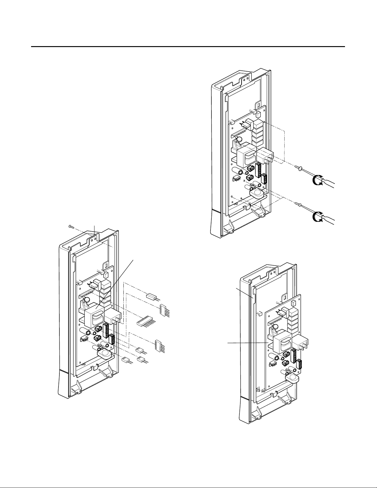
A. REMOVING POWER AND CONTROL
CIRCUIT BOARD (Figures 1, 2 and 3)
(1) Remove a screw securing the control panel
assembly to the oven cavity.
(2) Remove the control panel with pushing it upward.
(3) Remove the connector (CN1) and wire leads
(Relay2) from the circuit board.
(4) Remove 3 screws securing the circuit board.
(5) Remove the circuit board from the control bracket
carefully.
7-4
Figure 2
Control Bracket
Figure 3
Circuit Board
DISASSEMBLY INSTRUCTIONS
Figure 1
Control Panel
Screw
(CN2)
(CN4)
(CN5)
(RY2)
(CN1)
(CN6)
(CN7)
Power
Transformer
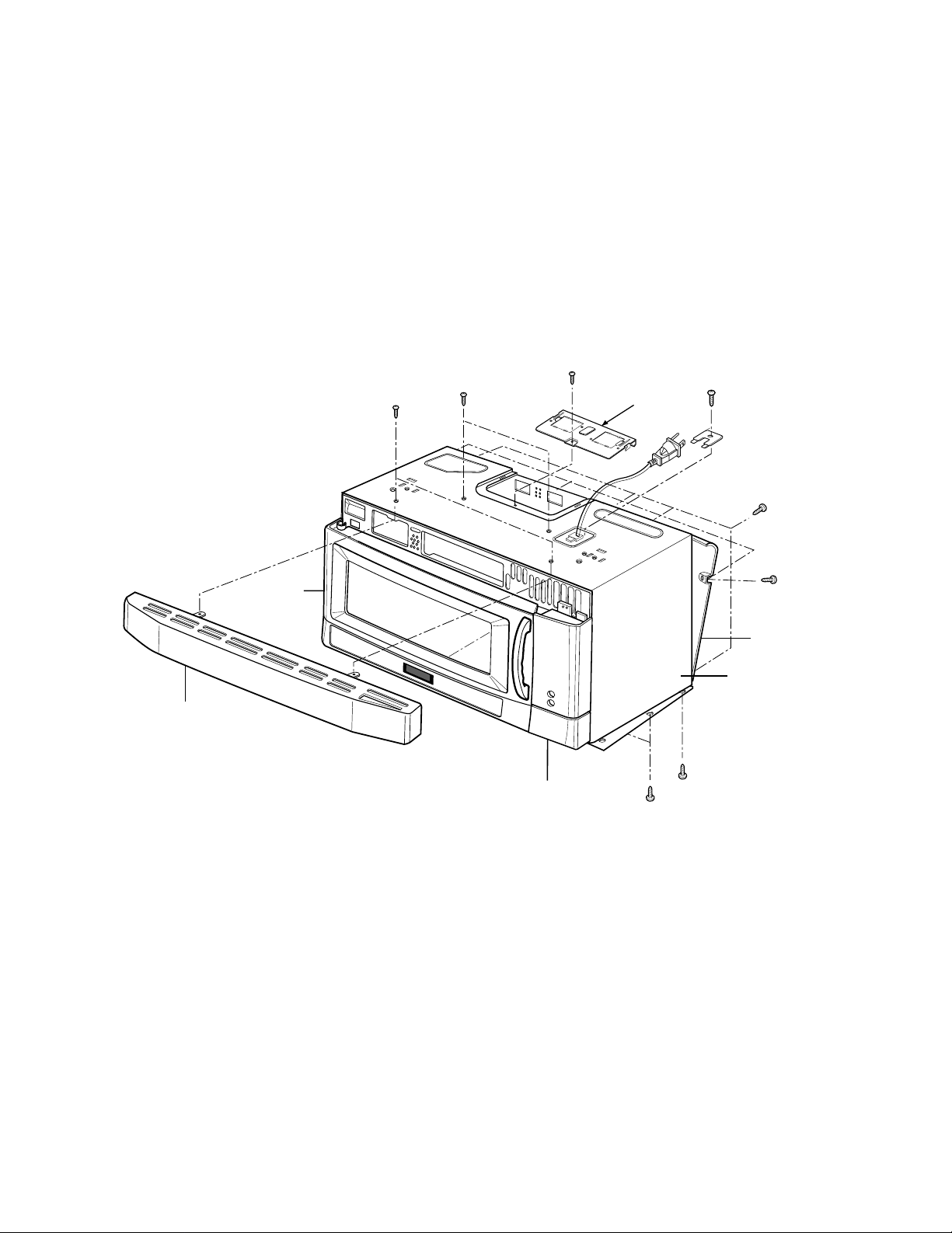
B. REMOVING THE OUT CASE(Figure 4)
(1) Remove the vent grille by removing two screws
securing it to the out case.
(2) Remove two screws securing it to the air duct.
(3) Remove the mounting plate by turning the screws
(1 or 2 screws) securing it to the out case.
(4) Remove two screws on the left central edge and
two screws on the right central edge of Base plate.
Remove the Mount, All from the out case by
removing one screw securing it to the out case.
(5) Remove the outcase with disconnecting power
cord connector.
Vent Grille
Controller
Door
Mounting
Plate
(1 or 2 screws)
Out Case
Mount,All
Figure 4
7-5
7-6
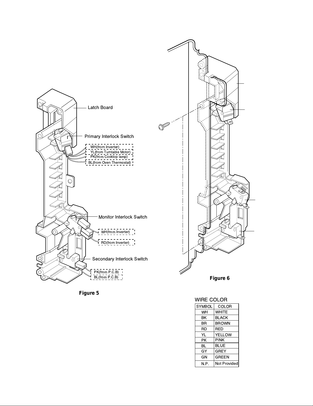
C REMOVING THE DOOR INTERLOCK
SWITCHES (Figures 5, 6)
(1) Disconnect the wire leads from the interlock
switches.
(2) Remove two screws securing the Latch Board.
(3) Make necessary replacements and check
microwave energy leakage according to
“ADJUSTMENT PROCEDURES” on page 7-11.
Latch Board
Secondary
Interlock Switch
Interlock
Monitor Switch
Interlock Switch
Primary
Latch Board
WH
(from Inverter)
YL(from Turntable Motor)
PK(from Cooktop lamp)
BL(from Oven Thermostat)
Secondary Interlock Switch
Monitor Interlock Switch
Primary Interlock Switch
PK(from P.C.B)
BL(from P.C.B)
WH(from Inverter)
RD(
from Inverter)
Figure 5
Figure 6
WIRE COLOR
SYMBOL COLOR
WH
BK
BR
RD
BL
PK
GY
N.P.
WHITE
BLACK
BROWN
RED
YL
YELLOW
BLUE
PINK
GREY
GN
GREEN
Not Provided
 Loading...