

LG LMVH1750, LMVM2055, LMV2053 User Manual

http://us.lgservice.com
MICROWAVE OVEN
INSTALLATION INSTRUCTIONS
PLEASE READ AND SAVE THESE INSTALLATION INSTRUCTIONS.
P/NO.: 3828W5U0492
삼 흥
정 판
– 2 –
YOUR SAFETY FIRST
BEFORE YOU START
• Proper installation is the installer's responsibility!
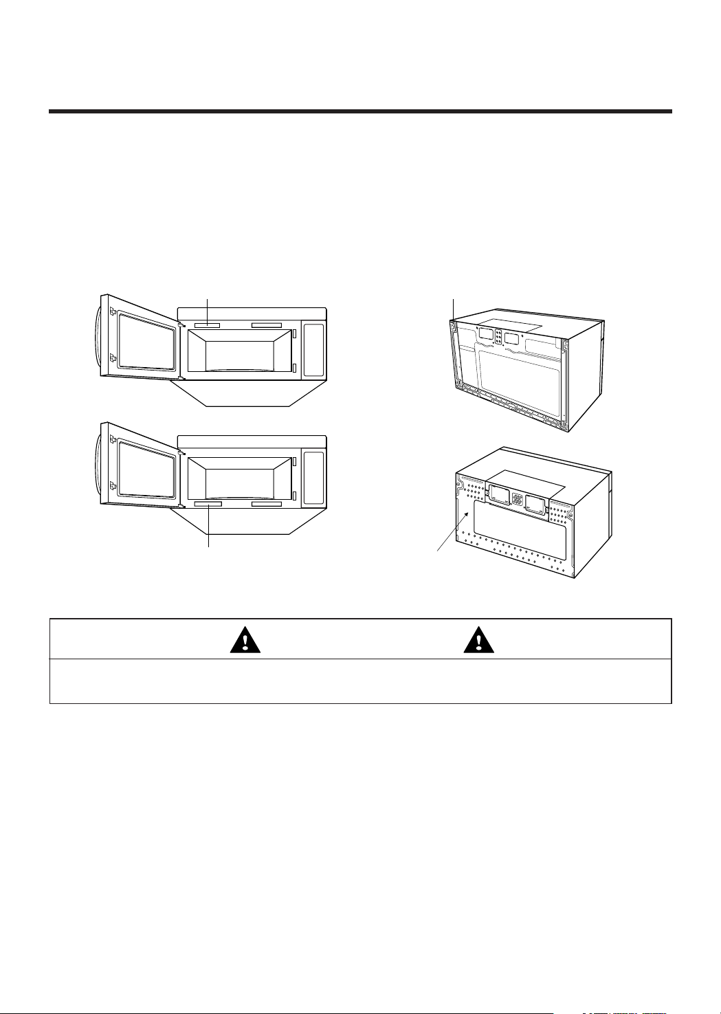
– Read the entire manual before you begin. The Model number label is located on the front of oven,
behind doon See Figure 1. Mounting plate is located on back side of microwave oven.
See Figure 2.
BE SURE TO READ THE FOLLOWING SAFETY INSTRUCTIONS:
• You will need TWO people to install this oven. It is heavy and could cause personal injury if not handled
properly.
• Avoid Electrical Shock!
– Before you drill into the wall, note where electrical outlets are and where electrical wires might be behind
concealed in the wall, YOU COULD RECEIVE AN ELECTRICAL SHOCK if you contact electrical wires with
your
drill bit.
– Locate and disconnect the power of any electrical circuits that could be affected by installing this oven.
IF YOU DO NOT DISCONNECT THE POWER, YOU RECEIVE AN ELECTRICAL SHOCK.
• ELECTRICAL RATING OF THIS OVEN : 120V AC. 60Hz.
– You need a 120V, 60Hz, AC only, 15A or 20A, fused electrical supply (located in the cabinet above the
microwave as close as possible to the microwave circuit) serving only the microwave.
Mounting Plate
Model Number Plate
Model Number Plate
Mounting Plate
Figure 1 Figure 2
For Your Safety
WARNING
– 3 –
YOUR SAFETY FIRST
• THIS APPLIANCE MUST BE GROUNDED!
– If there is an electrical short circuit, grounding reduces the risk of electrical shock by providing an escape
wire for the electric current. This appliance is equipped with a cord having a grounding wire with a grounding
plug.
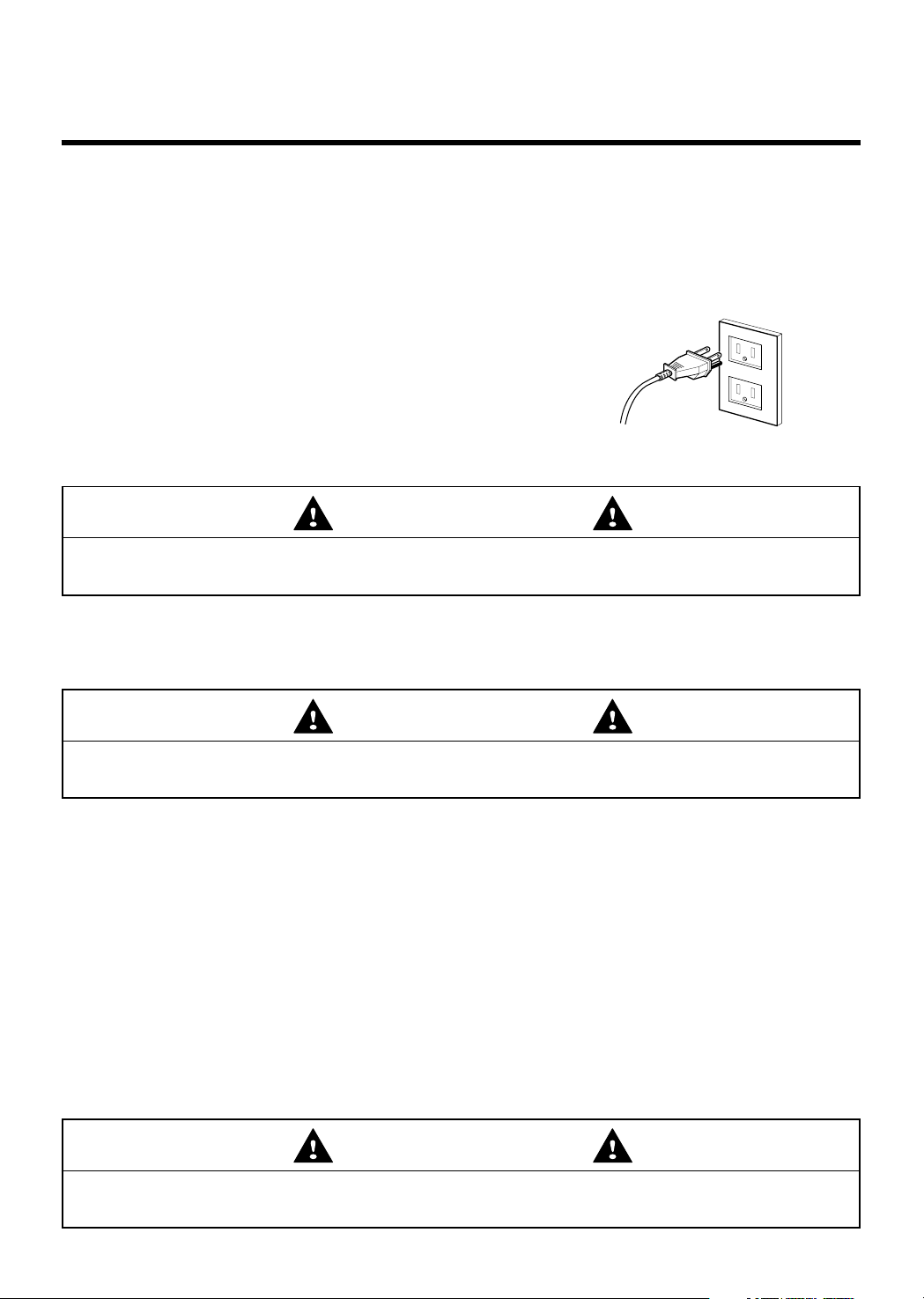
• Place the plug into a properly installed and grounded outlet. See Figure 3.
• Do not use an extension cord.
• Keep the power cord dry and do not pinch or crush it.
• DO NOT, UNDER ANY CIRCUMSTANCES, REMOVE THE
POWER SUPPLY CORD GROUNDING PRONG!
This appliance MUST be grounded!
Check with a qualified electrician if you are not sure whether the oven is properly grounded or if you do not
completely understand the grounding instructions.
DO NOT USE A FUSE IN THE NEUTRAL OR GROUNDING CIRCUIT.
SAVE THESE INSTRUCTIONS FOR THE LOCAL ELECTRICAL INSPECTOR'S USE.
• DO NOT EXPOSE YOURSELF TO EXCESSIVE MICROWAVE ENERGY!
– DO NOT try to operate the microwave oven with the door open.
– DO NOT tamper with or defeat the safety interlocks.
– DO NOT place objects between the microwave oven front face and the door.
– DO NOT allow soil or cleaner residue to build up on the flat surfaces around the microwave oven door.
– DO NOT operate the microwave oven if it is damaged.
– The microwave oven door must close properly to operate safely.
– DO NOT USE THE MICROWAVE OVEN:
• If the door is bent.
• If the hinges or latches are broken or loose.
• If the door seals, sealing surfaces or glass is broken.
– DO NOT ATTEMPT TO ADJUST OR REPAIR THE OVEN YOURSELF!
It should be adjusted and repaired by a qualified technician who can check for microwave leakage after
repairing the oven.
PROPERLY POLARIZED AND
GROUNDED OUTLET
Three-Pronged (Grounding) Plug
Figure 3
If you use the grounding plug improperly, you risk electric shock and or fire!
WARNING
Improper grounding could result in electric shock, fire or other personal injury.
WARNING
If you do not use the microwave oven as instructed,
you could be exposed to excessive microwave energy.
WARNING
– 4 –
YOUR SAFETY FIRST
• MAKE SURE YOU HAVE ENOUGH SPACE AND SUPPORT.
– Mount the oven against a flat, vertical wall, so that it is supported by the wall. The wall should be
constructed of minimum 2" x 4" wood studding and 3/8" thick drywall or plaster/lath.
– ATTACH AT LEAST ONE of the two lag screws supporting the oven to a vertical, 2" x 4" wall stud.
– DO NOT mount the microwave oven to an island or peninsula cabinet.
– BE SURE the upper cabinet and rear wall structures are able to support 150 lbs., plus the weight of any
items you place inside the oven or upper cabinet.
– Locate the oven away from strong draft areas, such as windows, doors, and strong heating vents.
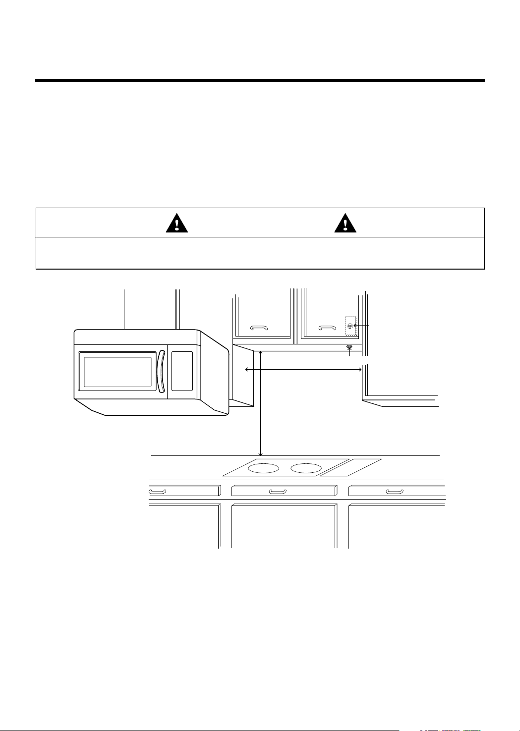
– BE SURE you have enough space. See Figure 4 below for minimum vertical and horizontal clearance.
CAUTION
• Before you begin installing the oven, PLACE A PIECE OF THE CARTON OR OTHER HEAVY
MATERIAL (a blanket) over the countertop or cooktop to protect it. Do not use a plastic cover.
Failure to protect these surfaces could result in property damage.
30" min. cabinet opening width
30" min. clearance from bottom
of cabinet to cooking surface
or countertop before installation.
Grounded Outlet
(inside upper cabinet)
Power Supply Cord Hole
(Use templates included
with installation instructions)
Figure 4
If you do not mount the oven as instructed,
you risk personal injury and/or property damage.
WARNING
– 5 –
PARTS, TOOLS, MATERIALS
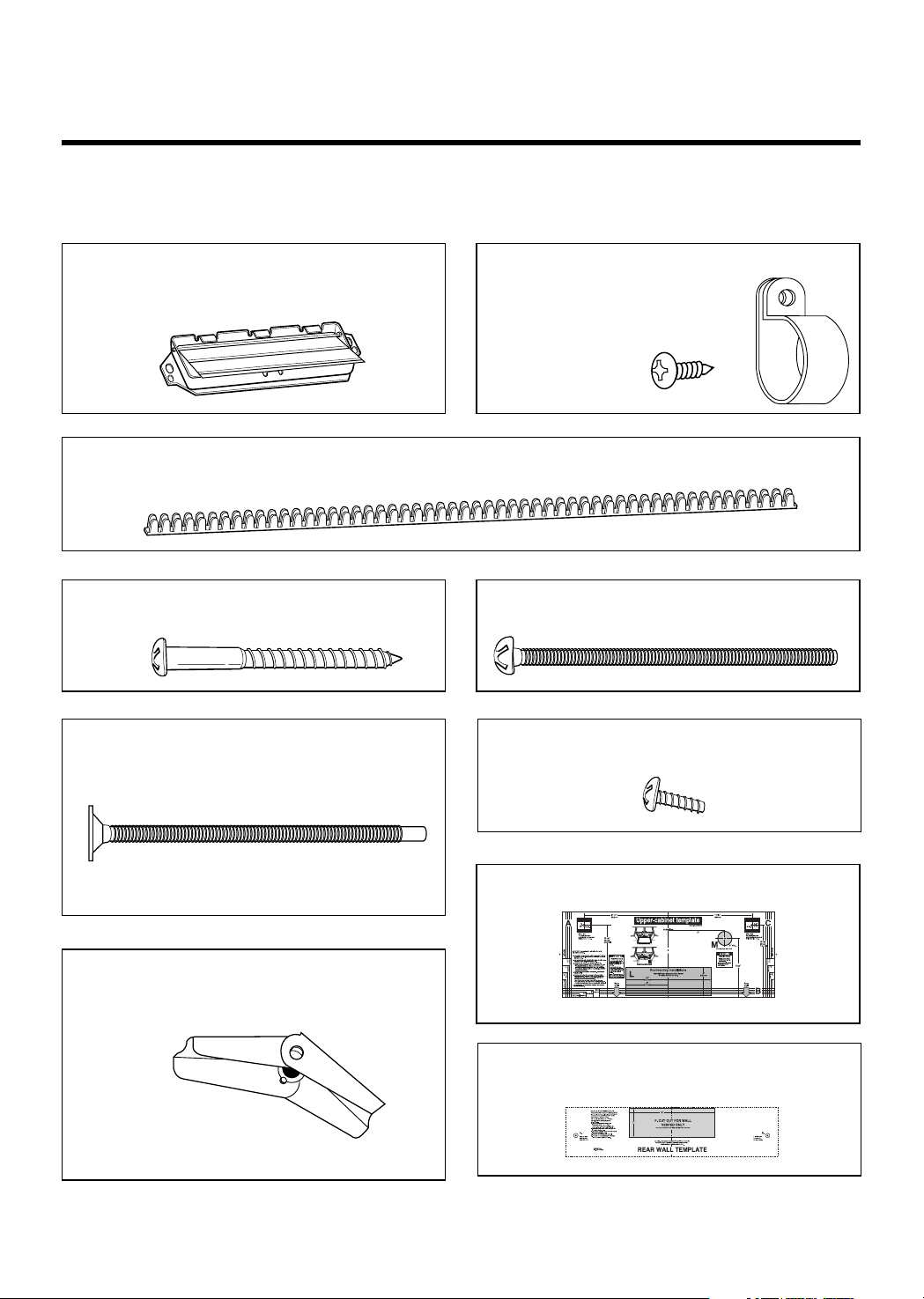
THE FOLLOWING PARTS ARE SUPPLIED WITH THE OVEN:
NOTE: Depending on your ventilation requirements, you may not use all of these parts.
Damper/duct connector
(for roof venting or wall venting installation)
Not Actual Size (2 pieces must be assembled as
shown)
One power cord clamp and
One dark-colored mounting screw
(to hold the power cord)
Actual Size
Two tapping screws - Actual Size
(for attaching the damper duct connector)
One power cord clamp bushing - Actual Size (for the cord hole in a metal upper cabinet)
NOTE: You need to install at least two lag screws into a 2" x 4" stud and four anchor bolts into the wall.
and the mounting area must meet the 150 lbs. weight requirement.
Four 1/4" x 2" lag screws - Actual Size
(for wall stud holes)
Four 1/4" x 3" toggle bolts - Actual Size
(for drywall holes)
Two 1/4" x 3" bolts - Actual Size
(for securing to the upper cabinet)
Four spring toggle heads - Actual Size
(for the toggle bolts)
One upper cabinet template- Not Actual Size
One rear wall template- Not Actual Size
(3 pieces mounting plate only)
– 6 –
PARTS, TOOLS, MATERIALS
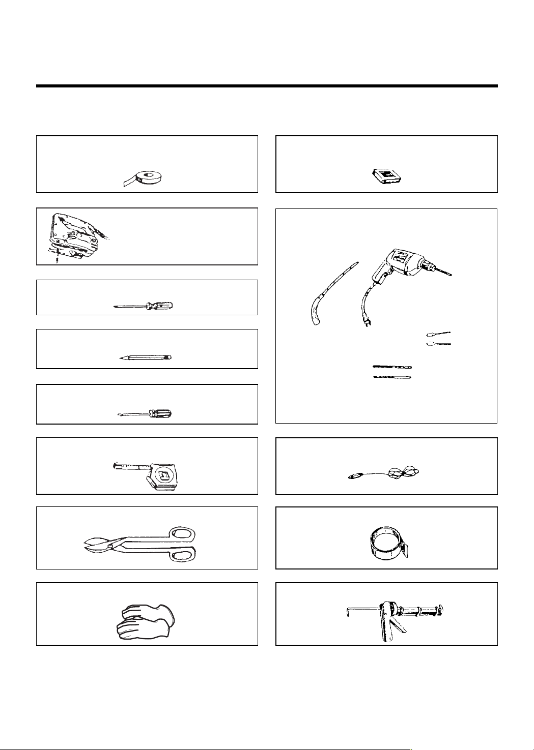
You will need the following tools and materials for the installation:
Carton or other heavy material for covering the counter top.
Clear Tape
(for taping the templates to the wall)
Stud Finder
Phillips Screwdriver
Pencil
Flat Blade Screwdriver
Measuring Tape
Small Side Cutters or Tin Snips
Gloves
Keyhole Saw (for the power cord hole)
3/8" and 3/4" wood drill bits
1/2" and 3/16"
drill bits
Plumb Line
Duct Tape
Caulking Gun
Electric Drill
●
If you have brick or masonry walls, you will need special hardware and tools.
●
The ductwork you need for the installation is not included. All wall and roof caps must have a back-draft damper.
(Shown on page 5).
Saber Saw
(for cutting vent holes for roof
or wall venting)
 Loading...