

Lg Lmv1813sw, Lmv1813sb, Lmv1813st Installation Guide

삼 흥
정 판
Internal Use Only
Website: http://biz.lgservice.com
MICROWAVE OVEN
SERVICE MANUAL
MODEL: LMV1813SW
CAUTION
BEFORE SERVICING THE UNIT, READ THE
SAFETY PRECAUTIONS IN THIS MANUAL.
P/NO : MFL06272514
LMV1813SB
LMV1813ST
February, 2010
Printed in China

CAUTION
WARNING TO SERVICE TECHNICIANS
PRECAUTIONS TO BE OBSERVED BEFORE AND
DURING SERVICING TO AVOID POSSIBLE EXPOSURE
TO EXCESSIVE MICROWAVE ENERGY
a. Do not operate or allow the oven to be operated with the door open.
b. Make the following safety checks on all ovens to be serviced before activating the
magnetron or other microwave source, and make repairs as necessary; (1) Interlock
operation, (2) proper door closing, (3) seal and sealing surfaces (arcing, wear, and
other damage), (4) damage to or loosening of hinges and latches, (5) evidence of
dropping or abuse.
c. Before turning on microwave power for any service test or inspection within the
microwave generating compartments, check the magnetron, wave guide or
transmission line, and cavity for proper alignment, integrity, and connections.
d. Any defective or misadjusted components in the interlock, monitor, door seal, and
microwave generation and transmission systems shall be repaired, replaced, or
adjusted by procedures described in this manual before the oven is released to the
owner.
e. A Microwave leakage check to verify compliance with the Federal performance
standard should be performed on each oven prior to release to the owner.
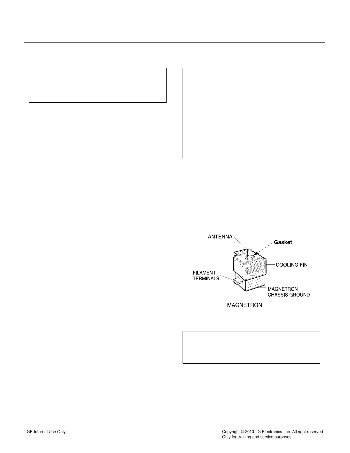
• Proper operation of the microwave ovens requires that the magnetron be assembled to the wave guide and
cavity.Never operate the magnetron unless it is properly installed.
• Be sure that the magnetron gasket is properly installed around the dome of the tube whenever installing the
magnetron.
• Routine service safety procedures should be exercised at all times.
• Untrained personnel should not attempt service without a thorough review of the test procedures and safety
information contained in this manual.
-2-

FOREWORD
Read this Manual carefully. Failure to adhere to or observe the information in this Manual may result in exposing
yourself to the Microwave Energy normally contained within the oven cavity.
CONTENTS
(Page)
Safety Precautions .............................................................................................................................................. 2
1. Specification .................................................................................................................................................... 4
2. Cautions ........................................................................................................................................................... 5
3. Installation ....................................................................................................................................................... 6
4. Operation ......................................................................................................................................................... 7
4-1. Control Panel Features .............................................................................................................................. 7
4-2. Explanation of Control Panel...................................................................................................................... 8
5. Wiring Diagram / Key Matrix........................................................................................................................... 9
5-1. Wiring Diagram .......................................................................................................................................... 9
5-2. Key Matrix ............................................................................................................................................... 10
6. Troubleshooting ............................................................................................................................................ 11
6-1. General Information for Service ............................................................................................................... 11
6-2. Safety Caution.......................................................................................................................................... 12
6-3. Basic Check Summary............................................................................................................................. 13
6-4. Troubleshooting ....................................................................................................................................... 14
7. Microwave Leakage Test .............................................................................................................................. 25
8. Power Output Measurement......................................................................................................................... 27
9. Interlock System............................................................................................................................................ 28
9-1. Interlock Mechanism ................................................................................................................................ 28
9-2. Interlock Continuity Test........................................................................................................................... 30
10. Component Testing Information................................................................................................................ 31
11. Disassembly Instructions........................................................................................................................... 35
12. Exploded View ............................................................................................................................................. 43
-3-

1. SPECIFICATIONS
Rated Power Consumption ................................1815W maximum
(Microwave oven+Cook top lamps+Ventilation fan)
Microwave Output ...............................................1100W (IEC60705)
Frequency ..........................................................2450 MHz ±50 MHz
Power Supply .....................................................120 VAC, 60 Hz
Rated Current ....................................................14 Amp. (Microwave oven+Cook top lamps+Ventilation fan)
Magnetron Cooling .............................................Forced Air Cooling
Rectification .......................................................Rectification Voltage Double Half-Wave
Door Sealing ......................................................Choke System
Safety Devices ...................................................Magnetron Thermostat: Open at 150 °C ±5 °C
Close at 0 °C ±5 °C
............................................................................Oven Thermostat: Open at 145 °C ±5 °C
Close at 0 °C ±5 °C
............................................................................Fuse (20A)
............................................................................Primary Interlock Switch
............................................................................Secondary Interlock Switch
............................................................................Interlock Monitor Switch
Magnetron ..........................................................2M246 (LG)
Cook top Lamp ...................................................125V, 30W (Incandescent)
Warming Lamp ...................................................125V, 30W
Timer ..................................................................Digital,up to 99 min.(in each cooking stage)
Tray ....................................................................Tempered Safety Glass
Overall Dimensions ............................................2915/16
6
Oven Cavity Size ...............................................21
/8
” (W) x 16
” (W) x 10
7
/16
” (H) x 15
5
/8
”(H) x 14
5
/8
5
/8
” (D)
” (D)
Effective Capacity of Oven Cavity ......................1.8 Cu.ft.
Accessories ........................................................Owner ’s Manual &Cooking Guide, Installation Manual,
............................................................................Exhaust Adapter, Exhaust Damper, Mounting Kit and Filter,
............................................................................Rotating Ring Assembly, Glass Tray, Metal Rack, Defrost Plate.
SWITCH CHART
PRIMARY
SWITCH MODE
CONDITIONS
DOOR OPEN
DOOR CLOSED
NOTE: Use the above switch chart with circuit diagram on page 9.
INTERLOCK
SWITCH
COM
NO
OPEN OPEN CLOSE
CLOSE CLOSE OPEN
-4-
SECONDARY
INTERLOCK
SWITCH
COM
NO
INTERLOCK
MONITOR
SWITCH
COM
NC
2. CAUTIONS
Unlike other appliances,the microwave oven is
high-voltage and high-current equipment.
Though it is free from danger in ordinary use,
extreme care should be taken during repair.
• DO NOT operate on a 2-wire extension cord during repair
and use.
• NEVER TOUCH any oven components or wiring during
operation.
• BEFORE TOUCHING any parts of the oven, always
remove the power plug from the outlet.
• Remove your watches whenever working close to or
replacing the magnetron.
• DO NOT touch any parts of the control panel circuit. A
resulting static electric discharge may damage this
P.C.B.
• NEVER operate the oven with no load.
• NEVER injure the door seal and front plate of the oven
cavity.
• NEVER put iron tools on the magnetron.
• NEVER put anything into the latch hole and the interlock
switches area.
MICROWAVE RADIATION
Personnel should not be exposed to the
microwave energy which may radiate from the
magnetron or other microwave generating
device if it is improperly used or connection.
All input and output microwave connections,
waveguide,flange,and gasket must be secure
never operate the device without a microwave
energy absorbing load attached.
Never look into an open waveguide or antenna
while the device is energized.
• Proper operation of the microwave oven requires that
the magnetron be assembled to the waveguide and
cavity. Never operate the magnetron unless it is
properly installed.
• Be sure that the magnetron gasket is properly
installed around the dome of the tube whenever
installing the magnetron.
-5-
THE OVEN IS TO BE SERVICED ONLY
BY PROPERLY QUALIFIED SERVICE
PERSONNEL.
3. INSTALLATION
BEFORE YOU BEGIN, READ THE FOLLOWING INSTRUCTIONS COMPLETELY AND CAREFULLY.
PRECAUTIONS ON INSTALLATION
A. Plug the power supply cord into a 120V AC, 60Hz,
single-phase power source with a capacity of at
least 20 amperes.
B. Avoid placing the unit in a location where there is
direct heat or splashing water.
C. Install the unit on the mounting plate firmly.
D. Place the unit as far away as possible from TV,
radio, etc. to prevent interference.
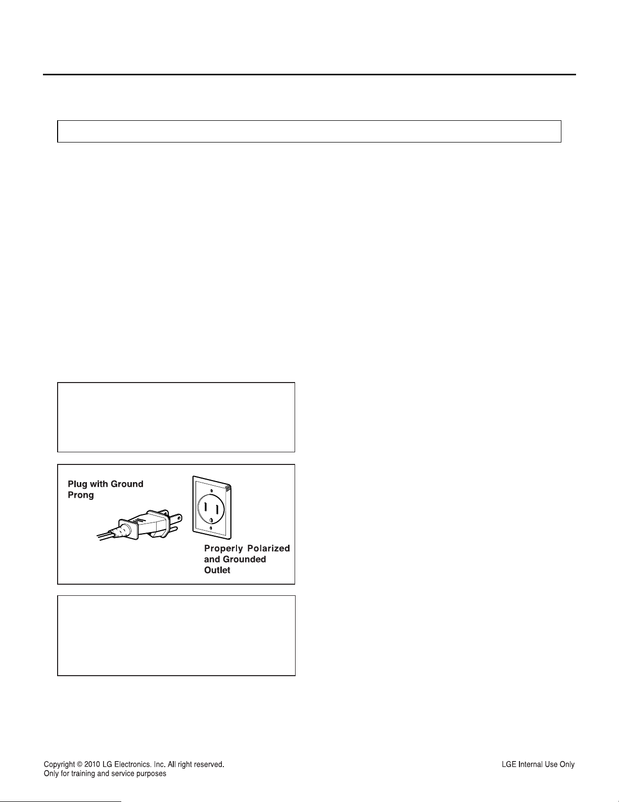
GROUNDING INSTRUCTIONS
For personal safety, this appliance must be fully
grounded at all times.
In the event of an electrical short circuit, grounding
reduces the risk of electrical shock.
The plug must be plugged into an outlet that is
properly installed and grounded.
CAUTION
This unit is equipped with a 3-prong plug for your
safety.If the wall outlet is a grounded 3-hole type,
the unit will be grounded automatically.
WARNING
Improper use of the grounding plug can result in a
risk of electric shock.
Do not, under any circumstances, cut or remove the
third ground prong from the power cord plug.
-6-
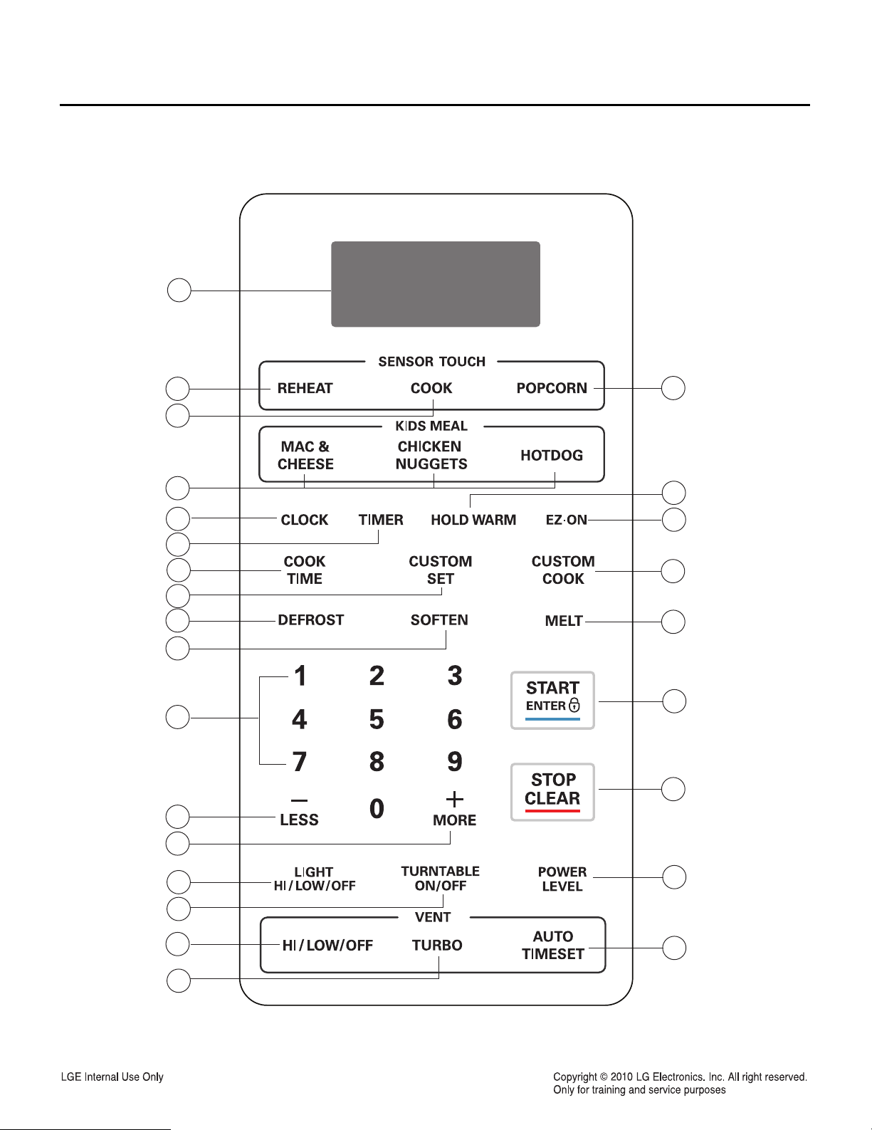
4. OPERATION
Control Panel Features
1
2
3
5
6
7
10
11
13
14
16
4
8
9
12
15
17
18
19
20
21
22
24
25
23
26
-7-

4-2. Explanation of Control Panel
NOTE: Styling and features vary by model.
1. DISPLAY The Display includes a clock and indicators to tell
you time of day, cooking time setting, and cooking functions
selected.
2. REHEAT Touch this pad to reheat Pizza Slice, Dinner
Plate, Soup/Sauce, and Casserole. The oven’s sensor will
tell the oven how long to cook depending on the amount of
humidity coming from the food
3. COOK Touch this pad to cook Baked Potato, Vegetable,
Casserole, Rice, and Frozen Entree. The oven’s sensor will
tell the oven how long to cook depending on the amount of
humidity coming from the food.
4. POPCORN Touch this pad when popping popcorn in your
microwave oven. The oven’s sensor will tell the oven how
long to cook depending on the amount of humidity it detects
from the popcorn.
5. KIDS MEAL Select type of dish to reheat HOT DOG, MAC
& CHEESE or CHICKEN NUGGETS.
6. CLOCK Touch this pad to enter the time of day.
7. TIMER Touch this pad to set the kitchen timer.
8. HOLD WARM Touch this pad to keep hot, cooked foods
warm in your microwave oven for up to 90 minutes.
9. EZ-ON Touch this pad to set and start quickly at
100%power level.
10. COOK TIME Touch this pad to to set a cooking time.
11. CUSTOM SET Touch this pad to change the oven’s default
setting for sound, clock, disply speed, and defrost weight.
12. CUSTOM COOK Touch this pad to recall one cooking
instruction previously programmed into memory.
14. SOFTEN Touch this pad to soften Butter, Ice Cream,
Cream Cheese, and Frozen Juice.
15. MELT Touch this pad to melt Butter / Margarine,
Chocolate, Cheese, and Marshmallows.
16. NUMBER Touch number pads to enter cooking time,
power level, quantities, or weights.
17. START/ENTER Touch this pad to start a function. If you
open the door after oven begins to cook, touch
START/ENTER again.
18. STOP/CLEAR Touch this pad to stop the oven or to clear
all entries.
19. LESS Touch this pad to subtract ten seconds of cooking
time each time you press it.
20. MORE Touch this pad to add ten seconds of cooking time
each time you press it.
21. LIGHT HI/LOW/OFF Touch this pad to turn the light on
high, low, or off.
22. TURNTABLE ON/OFF Touch this pad to turn on/off the
turntable. This option is not available in sensor cook and
detrost modes.
23. POWER LEVEL Touch this pad to select a cooking power
level.
24. VENT HI/LOW/OFF Touch this pad to turn the fan on high,
low, or off.
25. VENT TURBO Touch this pad to choose the most powerful
fan speed.
26. VENT AUTO TIME SET Touch this pad when setting
ventilation time. (1, 3, 5, 10, and 30 minutes.)
13. DEFROST Touch this key to defrost food by entering
weight, cook time or Quickly.
Touch this key 2 times to Quick Defrost Cook.
Touch this key 3 times to Time Defrost Cook.
-8-
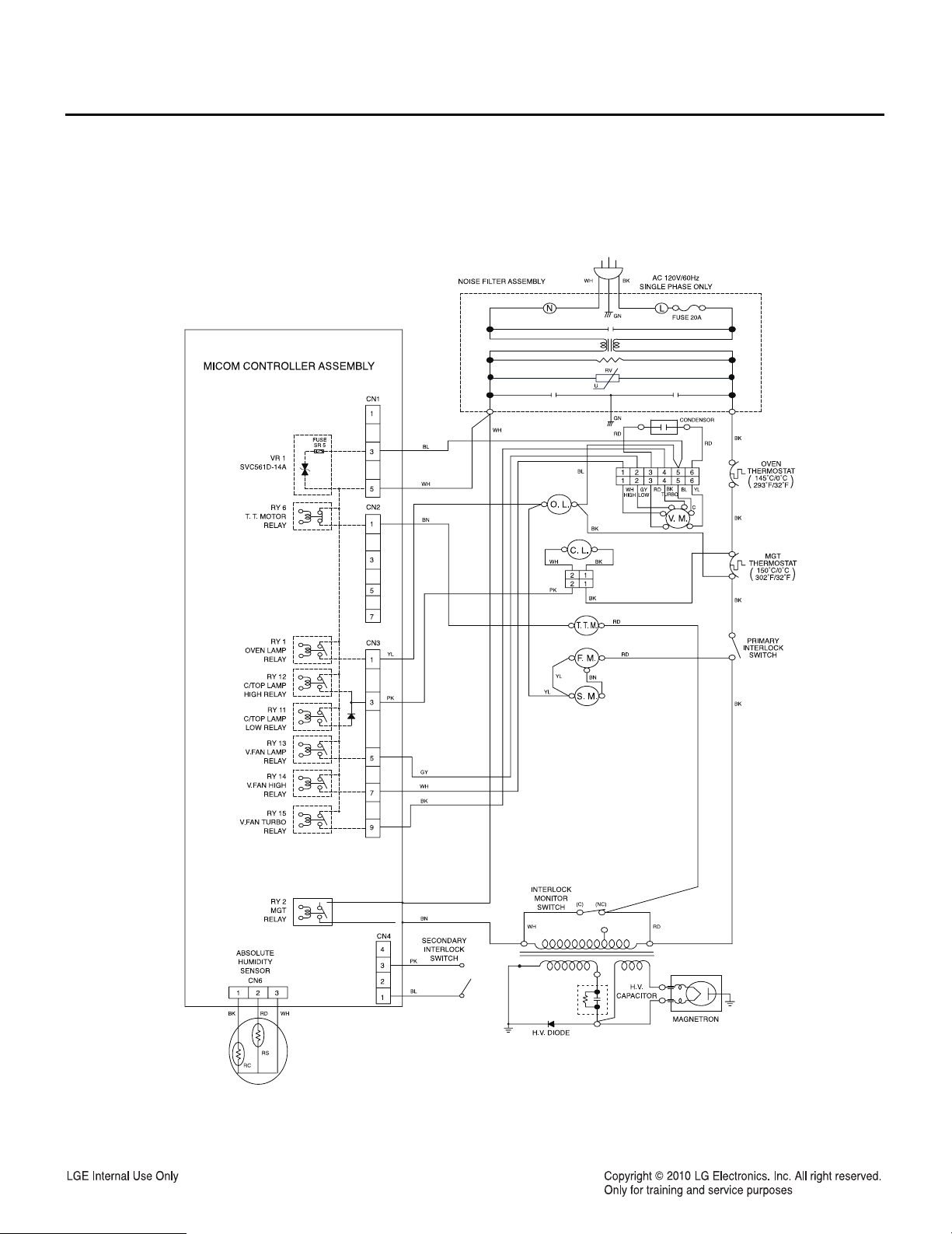
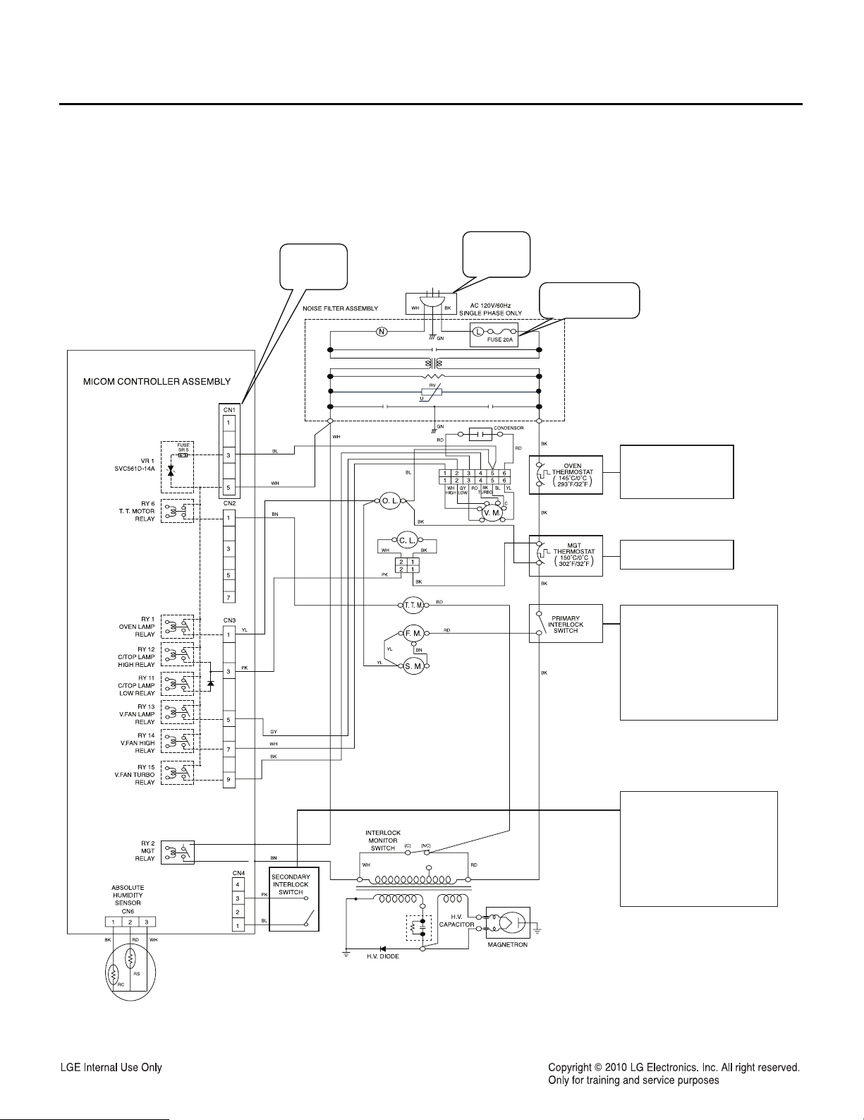
5. WIRING DIAGRAM / KEY MATRIX
5-1. Wiring Diagram
-9-

5-2. Key Matrix
KEY MATRIX
1
2
Hi / Low / OFF
3
(Vent On / Off)
4
56789101112913
1234 5678
CUSTOM
SET
VENT
SENSOR
POPCORN
TIME
COOK
TURBO
(Vent Speed)
SENSOR
COOK
POWER
LEVEL
LIGHT SOFTEN
SENSOR
REHEAT
WARMING
(Hold Warm)
MAC &
CHEESE
DEFROST
(Auto Defrost)
T/T ABLE
ON/OFF
STOP /
CLEAR
EZ-ON
(ADD30SEC)
Timer CLOCK NA
HOT DOG
ENTER /
START
MELT MORE
CHICKEN
NUGGETS
LESS
AUTO
Time Set
NA
NA
14
0
NA
NA
-10-

6. TROUBLESHOOTING
6-1. General Information for Service
GENERAL PRECAUTIONS IN USE
A. Never operate the unit when it is empty.
Operating the oven with no load may shorten the
life of the magnetron. Whenever cooking dry
foods (dried fish, bread, etc.) or a small amount of
food, be sure to put a glass of water into the
cooking compartment. The glass turntable may
become hot after operating, be careful when
touching it.
B. Aluminum foil should be avoided because it will
disrupt cooking and may cause arcing. However,
small pieces may be used to cover some parts of
food to slow the cooking. Any aluminum foil used
should never be closer than 2.5 cm to any side
wall of the oven.
TRIAL OPERATION
After installation, the following sequences and
results should be checked carefully.
A. Put a container filled with water (about 1 liter)into
the oven, and close the door tightly.
B. Set cooking time for 10 minutes.
C. Press the START pad to start.
Make sure the cavity light comes on. The unit will
begin cooking and the display window will show the
time counting down by seconds.
D. After about 5 minutes, make sure the primary
interlock switch, the secondary interlock switch
and the interlock monitor switch operate properly
by opening and closing the door several times.
Press the Press the START pad each time the
door is closed.
E. Continue operating the unit. For long beep sound
signal is heard when the time is up. The unit will
shut off automatically.
F. Confirm the water is hot.
G. Finally, measure the output power according to
POWER OUTPUT MEASUREMENT on
page 8.
FEATURES AND SPECIFICATIONS
FEATURES
A. The safety systems incorporated in this model
are:
(1) Primary interlock switch
(2) Secondary interlock switch
(3) Interlock monitor switch
(4) Choke system
(5) Oven cavity thermostat
(Note: This thermostat located on the oven
cavity will open and stop the unit from
operation only if a high temperature is
reached, such as, a fire created by
overcooking food.)
B. Any one of 10 power output levels ranging 0 W to
1,100 W can be selected by the touch control and
electronic computer system.
-11-

6-2. Safety Caution
A. SINCE NEARLY 4,000 VOLTS EXISTS IN
SOME CIRCUITS OF THIS UNIT REPAIRS
SHOULD BECARRIED OUT WITH GREAT
CARE.
The filament leads of magnetron carry High
Voltage with respect to ground. Extreme caution
must be exercised. Never plug the unit into a
power source to determine which component is
defective in high voltage section.
B. TO AVOID POSSIBLE EXPOSURE TO
MICROWAVE ENERGY LEAKAGE, THE
FOLLOWING PRECAUTIONS MUST BE TAKEN
BEFORE SERVICING.
(1) Before the power is applied:
(a) Make sure the primary interlock switch, the
secondary interlock switch and the interlock
monitor switch operate properly by opening
and closing the door several by opening and
closing the door several times.
(b) Make sure the perforated screen and the
dielectric choke of the door are correctly and
firmly mounted.
(2) After power is applied:
(a) Make sure the interlock switch mechanism
is operating properly by opening and closing
the door.
(b)
Check microwave energy leakage must be
below
the limit of 5 mW/cm2.
(All service adjustments should be made for
minimum microwave energy leakage
readings).
(3) Do not operate the unit until it is completely
repaired, if any of the following conditions exist.
The unit must not be operated.
(a) The door does not close firmly.
(b) The hinge is broken.
(c) The door seal is damaged.
(d) The door is bent or warped, or there is any
other visible damage on the unit that may
cause microwave energy leakage.
NOTE: Always keep the seal clean.
(e) Make sure that there are no defective parts
in the interlock mechanism.
(f) Make sure that there are no detective parts
in the microwave generating and
transmission assembly (especially
waveguide).
(4) The following items should be checked after the
unit is repaired:
(a) The interlock monitor switch is connected
correctly and firmly.
(b) The magnetron gasket is properly positioned
and mounted.
(c) The waveguide and the oven cavity are
intact.
(no microwave energy leakage)
(d) The door can be properly closed and the
safety switches work properly.
(e) The unit must stop when the door is opened
or the time is up.
The unit must not be operated with any of the above
components removed or bypassed.
-12-
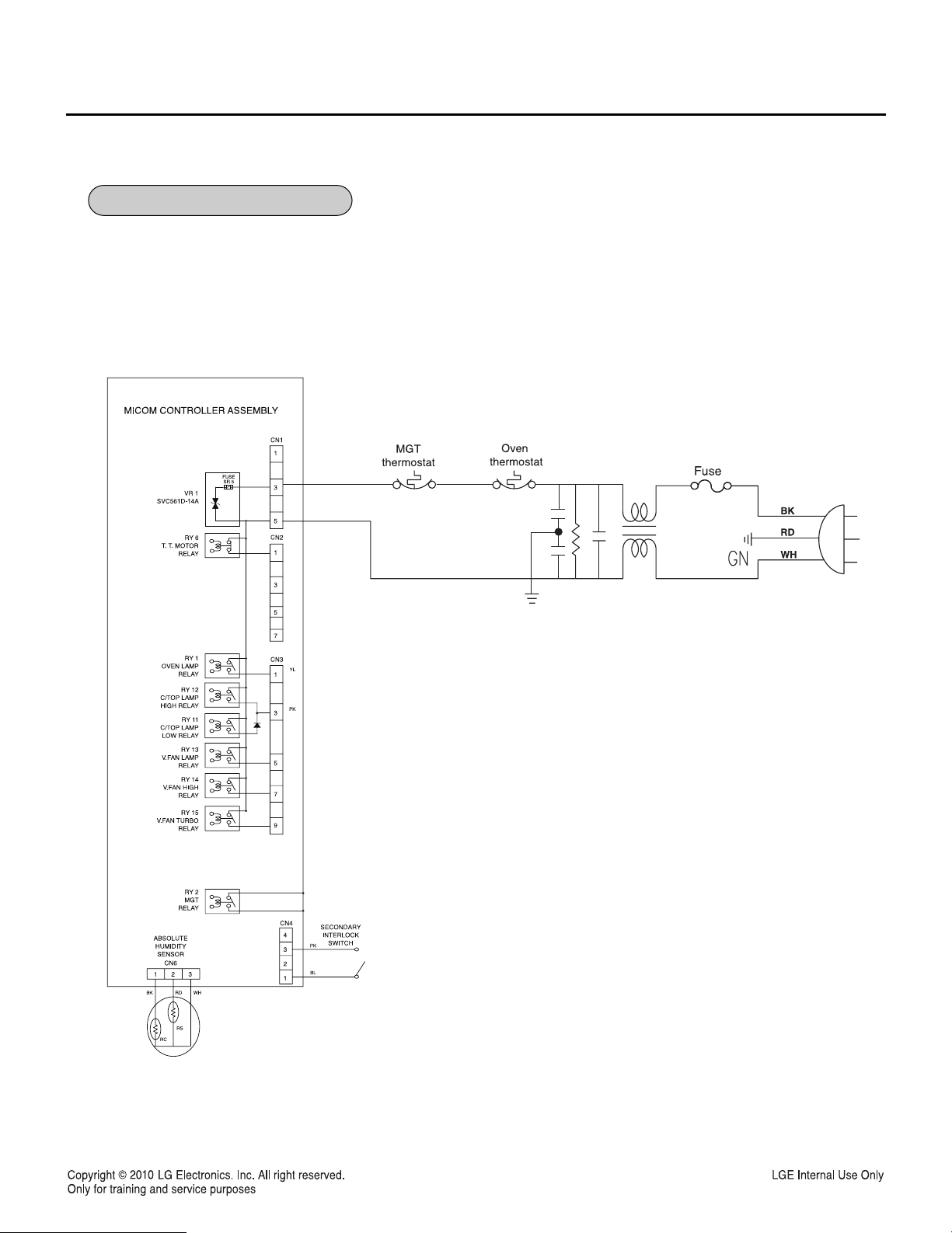
6-3. Basic Check Summary
120V Ac
BK-CN1-3
WH-CN1-5
120 V Ac
BK-L
WH-N
Symptom : Dead
Check : Open/Short
Symptom: Dead
Check : Open/Short
(It is normally recovered
if the set is cooled down)
Symptom: Dead
Check :Open/Short
Symptom #1(Door is closed): No
cook, Operate F.M, S.M, T.T.M.
automatically
Check: Open/Short when the door
is closed. (Switch)
Symptom #2(Door is open):
Not operate F.M, S.M, T.T.M.
Check: Open/Short when the door
is open. (Switch)
Symptom #1(Door is closed): No
key, Not start, Operating O.L, F.M,
S.M, T.T.M.
Check: Open/Short when the door
is closed. (Switch)
Symptom #2(Door is open): Not
turn on O.L
Check: Open/Short when the door
is open. (Switch)
-13-
6-4. Troubleshooting
No Display or Dead
-14-
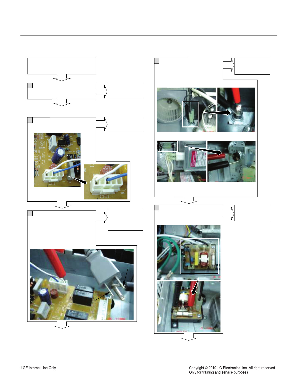
Does the display operate?
No
1
When you push the any key,
is there any beep sound
No
Power Off
2
Is the connector connected
to PCB?
Yes
Yes
Go to No.8 of
this flow chart.
Go to No.8 of
this flow chart.
4
Is there any beep sound in
continuity test between the
ends of thermostats? (Oven ,
Magnetron)
Oven Thermostat
Magnetron Thermostat
No
Replace the
thermostats.
No
3
Is there any beep sound in
continuity test between the
power code and connector?
Code “L” to Pin3
Code “N” to Pin5
No
Yes
5
Is there any beep sound in
Check PCB
Yes
Go to No.8 of
this flow chart.
NNN
N
N
N
N
N
N
N
N
N
N
N
N
N
N
N
N
N
N
N
LLL
L
L
L
L
L
L
L
L
L
L
L
L
L
L
L
L
L
L
L
continuity test between the
ends of the Fuse?
Yes
No
Replace the
Fuse.
-15-
 Loading...