

LG L3UH482FA0, L4UH602FA0, L3UC482NA1, L4UC602FA0, LMNC122LRL0 Service Manual
...
LG
Multi Type Air Conditioner
SERVICE MANUAL
LG
CAUTION
website http://www.lgservice.com
e-mail http://www.lgeservice.com/techsup.html
• BEFORE SERVICING THE UNIT, READ THE SAFETY
PRECAUTIONS IN THIS MANUAL.
• ONLY FOR AUTHORIZED SERVICE PERSONNEL.
MODEL Cooling Model Heating Model
• Outdoor Unit: L3UC482FA0 L3UH482FA0
L3UC482NA1
L4UC602FA0 L4UH602FA0
• Indoor Unit: LMNC122LRL0 LMNH122LRL0
LMNC182LTL0 LMNH182LTL0
LMNC242LTL0 LMNH242LTL0
LMNC122LRA0 LMNH122LRA0
LMNC182LTA0 LMNG182LTA0
LMNC242LTA0 LMNH242LTA0
LMNC122BTG0 LMNH122BTG0
LMNC182BTG0 LMNH182BTG0
LMNC242BHA0 LMNH242BHA0
L3NC122NRA1
L3NC242NRA1

2 Multi Type Air Conditioner
Multi Type Air Conditioner Service Manual
TABLE OF CONTENTS
Safety Precautions......................................................................................................................................3
Details of LG Model Name..........................................................................................................................7
Product Specifications...............................................................................................................................8
Combination Table....................................................................................................................................12
Dimensions................................................................................................................................................15
Refrigeration Cycle Diagram....................................................................................................................17
Schematic Diagram...................................................................................................................................19
Functions...................................................................................................................................................24
Operation Details ......................................................................................................................................31
2-way, 3-way V alve....................................................................................................................................38
Cycle Troubleshooting Guide ..................................................................................................................42
Electronic Parts Troubleshooting Guide.................................................................................................44
Disassembly of the parts (Indoor unit) ...................................................................................................50
Exploded View & Replacement Parts List ..............................................................................................53
Service Manual 3
Safety Precautions
Safety Precautions
To prevent injury to the user or other people and property damage, the following instructions must
be followed.
■ Incorrect operation due to ignoring instruction will cause harm or damage. The seriousness is
classified by the following indications.
■ Meanings of symbol used in this manual are as shown below.
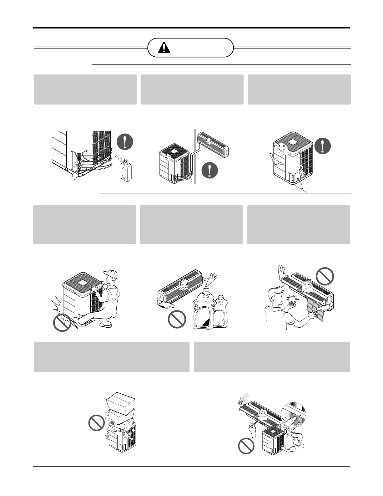
WARNING
CAUTION
This symbol indicates the possibility of death or serious injury.
This symbol indicates the possibility of injury or damage.
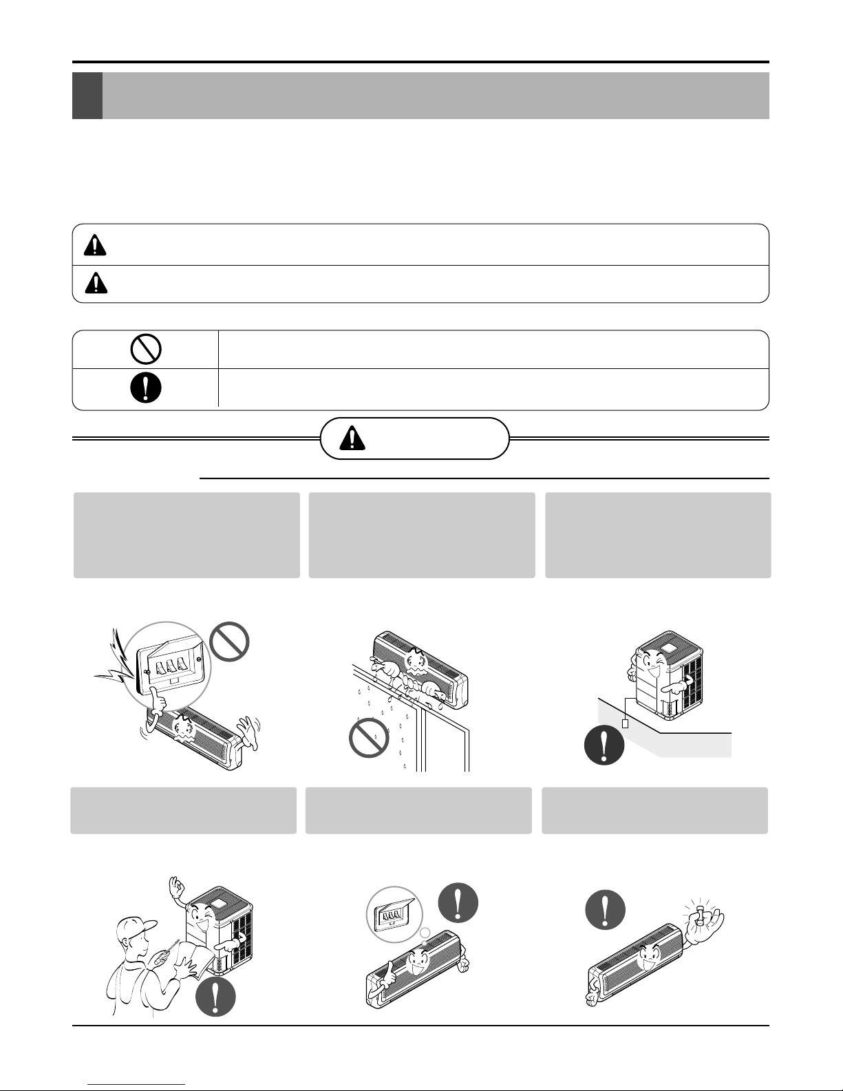
WARNING
■ Installation
Be sure not to do.
Be sure to follow the instruction.
Do not use a defective or
underrated circuit breaker.
Use this appliance on a dedicated circuit.
• There is risk of fire or electric shock.
Do not let the air conditioner
run for a long time when the
humidity is very high and a
door or a window is left open.
• Moisture may condense and wet or
damage furniture.
Always ground the product.
• There is risk of fire or electric shock.
Install the panel and the cover
of control box securely.
• There is risk of fire or electric shock.
Always install a dedicated circuit and breaker.
• Improper wiring or installation may
cause fire or electric shock
Use the correctly rated breaker or fuse.
• There is risk of fire or electric shock.
4 Multi Type Air Conditioner
Safety Precautions
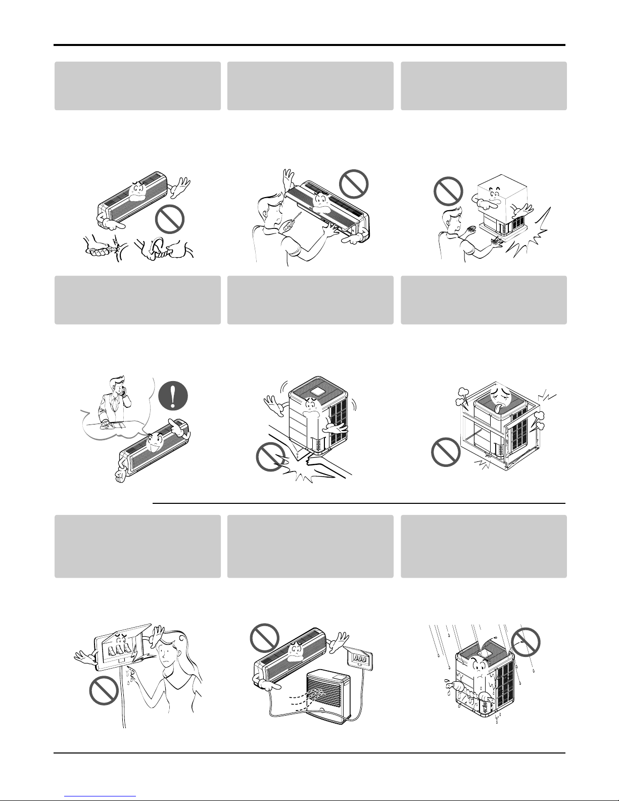
■ Operational
Do not modify or extend the
power cable.
• There is risk of fire or electric shock.
Do not install, remove, or reinstall the unit by yourself
(customer).
• There is risk of fire, electric shock,
explosion, or injury.
Be cautious when unpacking
and installing the product.
• Sharp edges could cause injury. Be
especially careful of the case edges
and the fins on the condenser and
evaporator.
For installation, always contact the dealer or an
Authorized Service Center.
• There is risk of fire, electric shock,
explosion, or injury.
Do not install the product on a
defective installation stand.
• It may cause injury, accident, or damage to the product.
Be sure the installation area
does not deteriorate with age.
• If the base collapses, the air conditioner could fall with it, causing property
damage, product failure, and personal
injury.
Do not touch(operate) the
product with wet hands.
• There is risk of fire or electrical shock.
Do not place a heater or other
appliances near the power
cable.
• There is risk of fire and electric shock.
Do allow water to run into
electric parts.
• It may cause There is risk of fire, failure of the product, or electric shock.
Service Manual 5
Safety Precautions
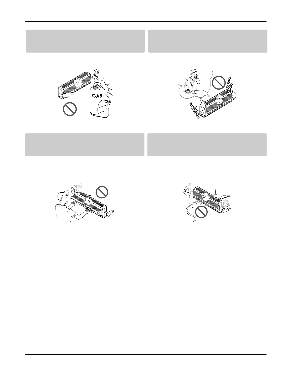
Do not open the inlet grille of the product during operation. (Do not touch the electrostatic
filter, if the unit is so equipped.)
• There is risk of physical injury, electric shock, or product failure.
Be cautious that water could not enter the
product.
• There is risk of fire, electric shock, or product damage.
Do not store or use flammable gas or combustibles near the product.
• There is risk of fire or failure of product.
If strange sounds, or smell or smoke comes
from product. Turn the breaker off or disconnect the power supply cable.
• There is risk of electric shock or fire.
Gasolin
6 Multi Type Air Conditioner
■ Operational
Safety Precautions
Use two or more people to lift
and transport the product.
• Avoid personal injury.
Use a soft cloth to clean. Do
not use harsh detergents, solvents, etc.
• There is risk of fire, electric shock, or
damage to the plastic parts of the product.
Do not touch the metal parts
of the product when removing
the air filter. They are very
sharp!
• There is risk of personal injury.
Do not step on or put anyting on the product.
(outdoor units)
• There is risk of personal injury and failure of product.
Do not insert hands or other objects through
the air inlet or outlet while the product is operated.
• There are sharp and moving parts that could cause personal
injury.
CAUTION
■ Installation
Wax
Thinner
check for gas (refrigerant)
leakage after installation or
repair of product.
• Low refrigerant levels may cause failure of product.
Install the drain hose to
ensure that water is drained
away properly.
• A bad connection may cause water
leakage.
Keep level even when
installing the product.
• To avoid vibration or water leakage.
90°
Details of LG Model Name
Details of LG Model Name
Outdoor Unit
L4UH602FA0
A: Basic
4: One outdoor unit can connect with four indoor
units(Reference to combination table)
Max. No. of indoor units
Development Sequence
Function
F: Free joint multi
Multi Type
48: 48,000 Btu/h 60: 60,000 Btu/h
Capacity
C: Cooling only H: Heat pump
Model Type
U: Outdoor N: Indoor
Outdoor / Indoor
L: Changwon of korea / R22
Making place / Refrigerant
2: 220V / 60Hz / 1Ø
Electric Standard (Volts / Freq. / Phase)
LMNH242LTL0
Development Sequence
A: Basic L: Plasma
Function
L: Changwon of korea / R22
Making place / Refrigerant
Indoor Unit
T: ST chassis R: SR chassis
Chassis Type
L: SR/ST chassis L look
Type
2: 220V / 60Hz / 1Ø
Electric standard (Volts / Freq. /Phase)
12: 12,000 Btu/h 24: 24,000 Btu/h
Capacity
C: Cooling only H: Heat pump
Model Type
U: Outdoor N: Indoor
Outdoor / Indoor
M: Multi
Multi Type
Service Manual 7
8 Multi Type Air Conditioner
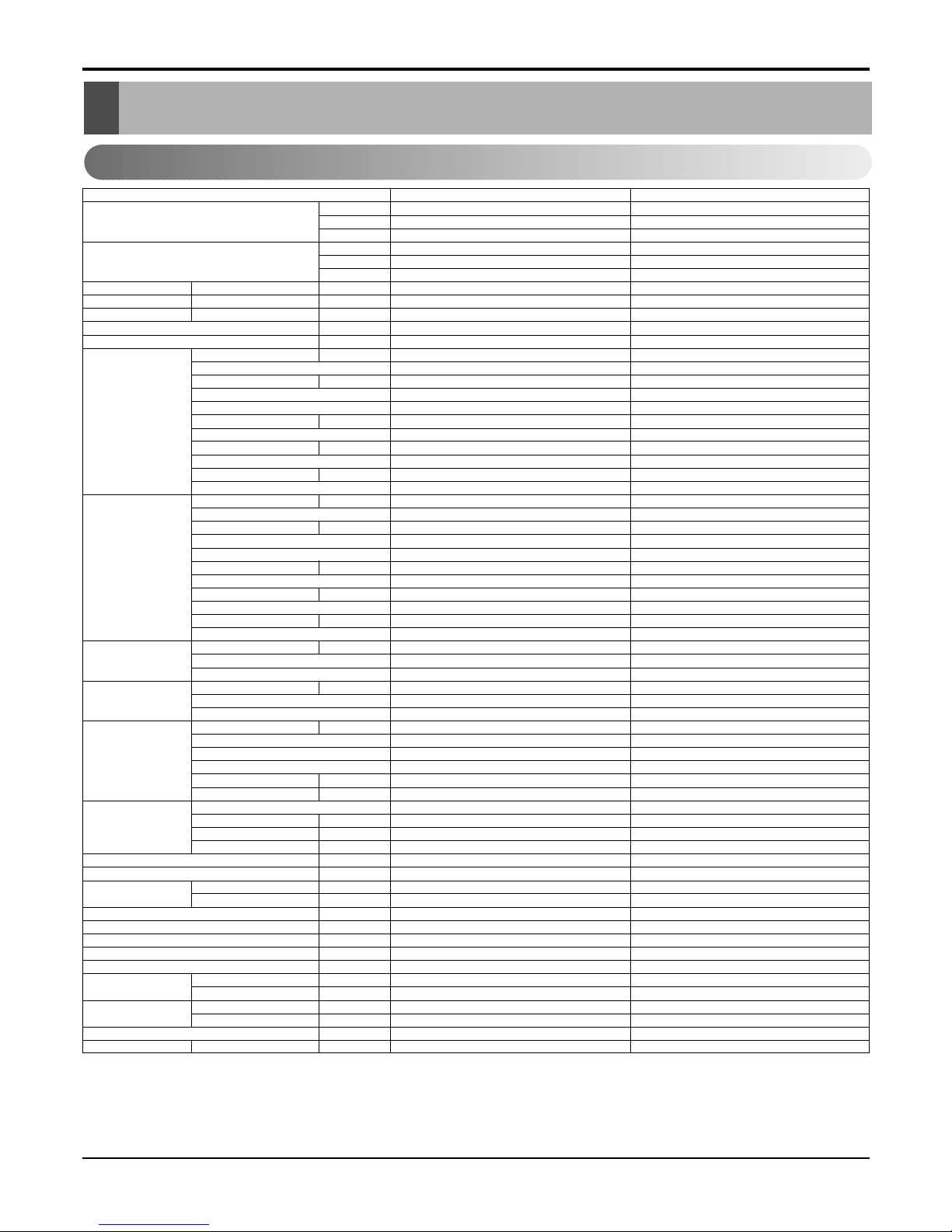
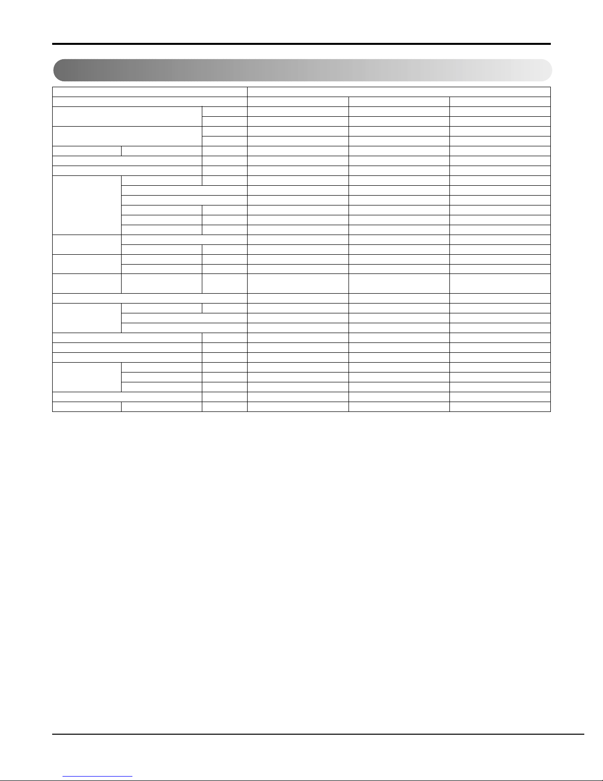
Product Specifications
Product Specifications
1. Outdoor
Notes:
1. Capacities are based on the following conditions:
Cooling: - Indoor Temperature 27°C(80.6°F) DB /19°C(66.2°F) WB
- Outdoor Temperature 35°C(95°F) DB /24°C(75.2°F) WB
- Interconnecting Piping Length 7.5m
- Level Difference of Zero.
2. Capacities are Net Capacities.
3. * : See Page "Combination Table"
Model
Cooling Capacity * kcal/h
W
Btu/h
Heating Capacity * kcal/h
W
Btu/h
Input * Cooling/Heating W
Running Current * Cooling/Heating A
Starting Current Cooling/Heating A
Power Supply Ø,V,Hz
Power Factor %
Compressor A Locked Rotor Amp. A
(TPS Cycle) Type
Quantity No
Model
Maker
Capacity kcal/h(Btu/h)
Motor Type
Motor Input W
Oil Type
Oil Charge cc
O.L.P Type(model name)
Compressor B Locked Rotor Amp. A
(Single Cycle) Type
Quantity No
Model
Maker
Capacity kcal/h(Btu/h)
Motor Type/Starting Type
Motor Input W
Oil Type
Oil Charge cc
O.L.P Type(model name)
Refrigerant Charge g(oz), type
Type
Control
Coil Tube Size (OD) inch(mm)
Fins per inch
No. of Rows & Column/No.
Fan Motor Output W
Model
No. of Poles
Input
Running Current A
Capacitor µF/Vac
Fan Type
No. Used / Diameter EA/inch(mm)
Discharge Side / Top
Speed rpm
Air Circulation CMM(CFM)
Noise Level(Sound Press,1m) dBA
SVC Valve Liquid inch(mm)
Gas inch(mm)
Drain(ID Ø)mm
Dimensions (W*H*D) inch(mm)
Net Weight kg(lbs)
Power Supply Cable No.* mm
2
Interunit Cable No.* mm
2
Max. Interunit Piping Total of Each Room m
Length For One Room m
Max. Installation Indoor Unit~Outdoor Unit m
Height Difference Indoor Unit~Indoor Unit m
Packing Dimension (W*H*D) inch(mm)
Stuffing Quantity Without S/Parts 20/40ft
L3UC482FA0 L3UH482FA0
3024~12096 3024~12096
3515~14067 3515~14067
12000~48000 12000~48000
- 3024~12096
- 3515~14067
- 12000~48000
1,460~5,360 1,460~5,360 / 1,540~5,640
6.8~24.7 6.8~24.7/ 7.1~26
--
1Ø, 220V, 60Hz 1Ø, 220V, 60Hz
98 98
35/26 35/26
Rotary Rotary
1/1 1/1
QJ208KAB/QK185KAF QJ208KAB/QK185KAF
LG/LG LG/LG
14650/12900 14650/12900
Single Phase Induction Motor / PSC Single Phase Induction Motor / PSC
1356/1205 1356/1205
ATMOS M60 or SUNISO 4GSI ATMOS M60 or SUNISO 4GSI
450/350 450/350
MRA98704~12026/MRA12070~12027 MRA98704~12026/MRA12070~12027
68 68
Rotary Rotary
11
QP348KD24B QP348KD24B
LG LG
25700 25700
Single Phase Induction Motor / PSC Single Phase Induction Motor / PSC
2424 2424
ATMOS M60 or SUNISO 4GSI ATMOS M60 or SUNISO 4GSI
700 700
Internal Internal
TPS Cycle : 1980(69.8) at 7.5m Single Cycle : 2140(75.5) at 7.5m TPS Cycle : 1980(69.8) at 7.5m Single Cycle : 2140(75.5) at 7.5m
R22 R22
L.E.V L.E.V
0.276(7.0) 0.276(7.0)
18 18
2R,36C 2R,36C
207 207
IC-13670 LG39F IC-13670 LG39F
66
340 340
1.5 1.5
6/400 6/400
Axial FAN Axial FAN
1/Ø20.7(526) 1/Ø20.7(526)
Top Discharge Top Discharge
1000 1000
80(2967) 80(2967)
60 60
1/4(6.35)*3EA 1/4(6.35)*3EA
1/2(12.7)*3EA 1/2(12.7)*3EA
--
28.0*32.6*27 (711 x 828 x 686) 28.0*32.6*27 (711 x 828 x 686)
120(264.5) 120(264.5)
3*4.5(Includes earth) 3*4.5(Includes earth)
4*0.75(Includes earth) 4*0.75(Includes earth)
50(TPS Cycle)+20(Single Cycle) 50(TPS Cycle)+20(Single Cycle)
30(TPS Cycle) 30(TPS Cycle)
30 15
7.5 7.5
33.5*35.0*30.1 (850 x 890 x 765) 33.5*35.0*30.1 (850 x 890 x 765)
40/84 40/84
Service Manual 9
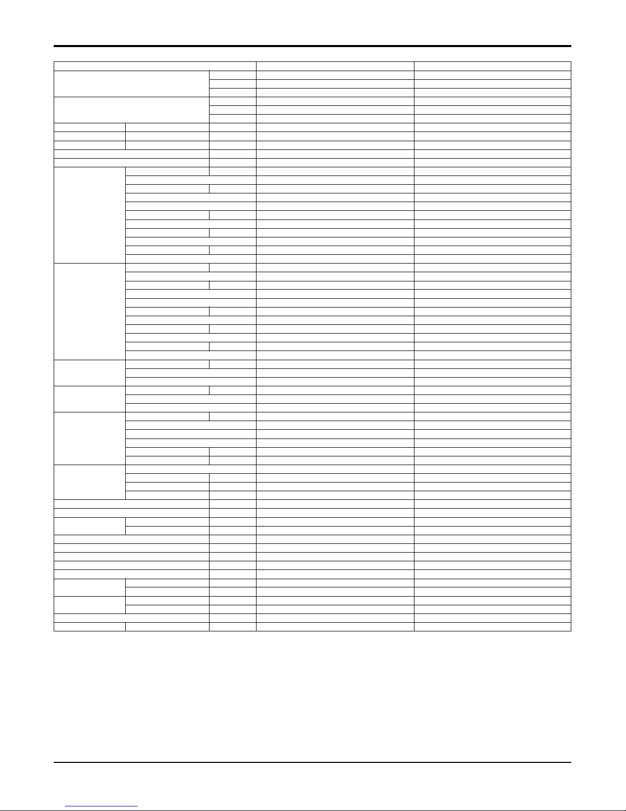
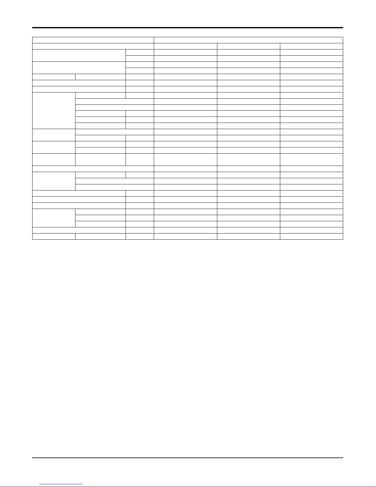
Product Specifications
Model
Cooling Capacity * kcal/h
W
Btu/h
Heating Capacity * kcal/h
W
Btu/h
Input * Cooling/Heating W
Running Current * Cooling/Heating A
Starting Current Cooling/Heating A
Power Supply Ø,V,Hz
Power Factor %
Compressor A Locked Rotor Amp. A
(TPS Cycle) Type
Quantity No
Model
Maker
Capacity kcal/h(Btu/h)
Motor Type
Motor Input W
Oil Type
Oil Charge cc
O.L.P Type(model name)
Compressor B Locked Rotor Amp. A
(Single Cycle) Type
Quantity No
Model
Maker
Capacity kcal/h(Btu/h)
Motor Type/Starting Type
Motor Input W
Oil Type
Oil Charge cc
O.L.P Type(model name)
Refrigerant Charge g(oz), type
Type
Control
Coil Tube Size (OD) inch(mm)
Fins per inch
No. of Rows & Column/No.
Fan Motor Output W
Model
No. of Poles
Input
Running Current A
Capacitor µF/Vac
Fan Type
No. Used / Diameter EA/inch(mm)
Discharge Side / Top
Speed rpm
Air Circulation CMM(CFM)
Noise Level(Sound Press,1m) dBA
SVC Valve Liquid inch(mm)
Gas inch(mm)
Drain(ID Ø)mm
Dimensions (W*H*D) inch(mm)
Net Weight kg(lbs)
Power Supply Cable No.* mm
2
Interunit Cable No.* mm
2
Max. Interunit Piping Total of Each Room m
Length For One Room m
Max. Installation Indoor Unit~Outdoor Unit m
Height Difference Indoor Unit~Indoor Unit m
Packing Dimension (W*H*D) inch(mm)
Stuffing Quantity Without S/Parts 20/40ft
L4UC602FA0 L4UH602FA0
3024~15120 3024~15120
3515~17584 3515~17584
12000~60000 12000~60000
- 3024~15120
- 3515~17584
- 12000~60000
1350~6000 1350~6000/1500~6400
6.5~28.0 6.5~28.0/7.0~30.0
--
1Ø, 220V, 60Hz 1Ø, 220V, 60Hz
95 95
68/26 68/26
Rotary Rotary
1/1 1/1
QP348KCC/QK185KAF QP348KCC/QK185KAF
LG/LG LG/LG
25700/12900 25700/12900
Single Phase Induction Motor / PSC Single Phase Induction Motor / PSC
2424/1205 2424/1205
ATMOS M60 or SUNISO 4GSI ATMOS M60 or SUNISO 4GSI
700/350 700/350
Internal/External Internal/External
68 68
Rotary Rotary
11
QP348KCE QP348KCE
LG LG
25700 25700
Single Phase Induction Motor / PSC Single Phase Induction Motor / PSC
2424 2424
ATMOS M60 or SUNISO 4GSI ATMOS M60 or SUNISO 4GSI
1130 1130
Internal Internal
TPS Cycle : 2500(88.2) at 7.5m Single Cycle : 1900(67.0) at 7.5m TPS Cycle : 2500(88.2) at 7.5m Single Cycle : 1900(67.0) at 7.5m
R22 R22
L.E.V L.E.V
0.276(7.0) 0.276(7.0)
18 18
2R,36C 2R,36C
260 260
IC-13670 LG39G IC-13670 LG39G
66
143 143
0.77 0.77
6/400 6/400
Axial FAN Axial FAN
1/Ø20.7(526) 1/Ø20.7(526)
Top Discharge Top Discharge
1040/840 1040/840
85(3002) 85(3002)
65 65
1/4(6.35)*4EA 1/4(6.35)*4EA
1/2(12.7)*4EA 1/2(12.7)*4EA
--
28.0*32.6*27 (711 x 828 x 686) 28.0*32.6*27 (711 x 828 x 686)
130(286.6) 130(286.6)
3*8.4(Includes earth) 3*8.4(Includes earth)
4*0.75(Includes earth) 4*0.75(Includes earth)
50(TPS Cycle)+20(Single Cycle) 50(TPS Cycle)+20(Single Cycle)
20(TPS Cycle) 20(TPS Cycle)
30 15
7.5 7.5
33.5*35.0*30.1 (850 x 890 x 765) 33.5*35.0*30.1 (850 x 890 x 765)
40/84 40/84
Notes:
1. Capacities are based on the following conditions:
Cooling: - Indoor Temperature 27°C(80.6°F) DB /19°C(66.2°F) WB
- Outdoor Temperature 35°C(95°F) DB /24°C(75.2°F) WB
- Interconnecting Piping Length 7.5m
- Level Difference of Zero.
2. Capacities are Net Capacities.
3. * : See Page "Combination Table"
10 Multi Type Air Conditioner
Product Specifications
2. Indoor
Indoor Unit Type
Model
Nominal Cooling Capacity* kcal/h(W)
Btu/h
Nominal Heating Capacity* kcal/h(W)
Btu/h
Air Circulation H/M/L CMM(CFM)
External Static Pressure mmAq
Setting temperature range(cool/heat) °C
Fan motor Output W
Model
No. of Poles
Input W
Running Current A
Capacitor µF/Vac
Fan Type
No. Used / Diameter EA/inch(mm)
Fan RPM Cooling(H/M/L) rpm
Heating(H/M/L) rpm
Noise Level
H/M/L dBA
(Sound Press,1m)
Temperature controller
Coil Tube Size (OD) inch(mm)
Fins per inch
No. of Rows & Column
Dehumidification Rate l/h
Dimensions (W*H*D) mm
Net Weight kg(lbs)
Piping Connection Liquid inch(mm)
Gas inch(mm)
Drain hose (ID Ø)mm
Packing Dimension (W*H*D) inch(mm)
Stuffing Quantity Without S/Parts 20/40ft
Wall Mounted
LMNC(H)122LRA0 LMNC(H)182LTA0 LMNC(H)242LTA0
3024(3516) 4536(5275) 6048/7032
12000 18000 24000
3024(3516) 4536(5275) 6048(7032)
12000 18000 24000
8.1(286) 12.3(435) 14.9(526)
---
18~30 / 16~30 18~30 / 16~30 18~30 / 16~30
10 15.7 35
IC8420LG*** IC8428LGB IC8420LG***
444
37 54 65.5
0.17 0.25 0.3
0.9 / 400 1.5/370 2.0 / 400
Cross Flow Fan Cross Flow Fan Cross Flow Fan
1/Ø43(87) 1/Ø43(87) 1/Ø43(87)
---
---
39/35/31 42/39/36 45/41/39
Thermistor Thermistor Thermistor
0.275(7) 0.275(7) 0.275(7)
20 20 20
2R,12C 2R,13C 2R,13C
1.4 2.2 2.9
35.4*11.2*6.1(900*285*156) 42.9*12.4*6.8 (1090*314*172) 42.9*12.4*6.8 (1090*314*172)
8(17.6) 12(26.5) 12(26.5)
1/4(6.35) 3/8(9.52) 3/8(9.52)
1/2(12.7) 5/8(15.88) 5/8(15.88)
16 16 16
38.4*14.6*9.2 (976 x 372 x 233) 45.9*15.3*10.0 (1165 x 388 x 255) 45.9*15.3*10.0 (1165 x 388 x 255)
340/720 270/540 270/540
1. * : See Page "Combination Table"
2. Due to our policy of innovation some specifications may be changed without notification.
Service Manual 11
Product Specifications
Indoor Unit Type
Model
Nominal Cooling Capacity* kcal/h(W)
Btu/h
Nominal Heating Capacity* kcal/h(W)
Btu/h
Air Circulation H/M/L CMM(CFM)
External Static Pressure mmAq
Setting temperature range(cool/heat) °C
Fan motor Output W
Model
No. of Poles
Input W
Running Current A
Capacitor µF/Vac
Fan Type
No. Used / Diameter EA/inch(mm)
Fan RPM Cooling(H/M/L) rpm
Heating(H/M/L) rpm
Noise Level
H/M/L dBA
(Sound Press,1m)
Temperature controller
Coil Tube Size (OD) inch(mm)
Fins per inch
No. of Rows & Column
Dehumidification Rate l/h
Dimensions (W*H*D) mm
Net Weight kg(lbs)
Piping Connection Liquid inch(mm)
Gas inch(mm)
Drain hose (ID Ø)mm
Packing Dimension (W*H*D) inch(mm)
Stuffing Quantity Without S/Parts 20/40ft
Ceiling Duct
LMNC(H)122BTG0 LMNC(H)182BTG0 LMNC(H)242BHA0
3024(3516) 4536(5274) 6048(7032)
12000 18000 24000
3024(3516) 4516(5274) 6048(7032)
12000 18000 24000
10/9/8(352/317/282) 13.5/12/10(477/424/353) 20/18/16(706/636/565)
228
18~30 / 16~30 18~30 / 16~30 18~30 / 16~30
35 126 60
YDK110*** YSK110**** IC-13450LG**
444
68 126 140
0.31 0.58 0.8
2.5 / 400 2.5/370 6 / 370
Sirocco Fan Sirocco Fan Sirocco Fan
1/7.8(197) 2/7.8(197) 2/7.0(177)
- 1130/1030/960
- 1130/1030/960
37/34/31 38/36/34 37/35/33
Thermistor Thermistor Thermistor
0.276(7.0) 0.276(7.0) 0.276(7.0)
18 18 21
3R,12C 2R,12C 3R,10C
1.2 2 3
25.6*9.0*21.1(650*230*535) 39.4*11.8*21.1(1000*230*535) 34.6*10.2*17.7(880*260*450)
22(48.5) 29(63.9) 35(77.2)
1/4 (6.35) 1/4(6.35) 1/4(6.35)
3/8 (9.52) 1/2(12.7) 5/8(15.88)
22.6 25.4 22.6
29.9*24.9*11.8(760*626*300) 49.5*11.8*24.6(1258*300*625) 44.7*13.4*23.0(1135*340*585)
172/356 123/251 48/101
1. * : See Page "Combination Table"
2. Due to our policy of innovation some specifications may be changed without notification.
1 UNIT 12(S-RAC) 12 13000 13000 1460 6.8
12(DUCT) 12 12000 12000 1460 6.8
18(S-RAC) 18 18000 18000 2190 10.2
18(DUCT) 18 18000 18000 2190 10.2
24(S-RAC) 24 22000 22000 2600 12.1
24(DUCT) 24 24000 24000 2600 12.1
24(S-RAC) 24 22000 22000 2600 12.1
24(DUCT) 24 24000 24000 2600 12.1
2 UNIT 12(S-RAC) 12(S-RAC) 24 12500 12500 25000 2760 12.6
12(DUCT) 12(DUCT) 24 12000 12000 24000 2760 12.6
12(S-RAC) 24(S-RAC) 36 13000 22000 35000 4060 18.9
12(DUCT) 24(DUCT) 36 12000 24000 36000 4060 18.9
18(S-RAC) 24(S-RAC) 42 18000 22000 40000 4740 22.1
18(DUCT) 24(DUCT) 42 18000 24000 42000 4740 22.1
24(S-RAC) 24(S-RAC) 48 22000 22000 44000 5360 24.7
24(DUCT) 24(DUCT) 48 24000 24000 48000 5360 24.7
3 UNIT 12(S-RAC) 12(S-RAC) 24(S-RAC) 48 12500 12500 22000 47000 5360 24.7
12(DUCT) 12(DUCT) 24(DUCT) 48 12000 12000 24000 48000 5360 24.7
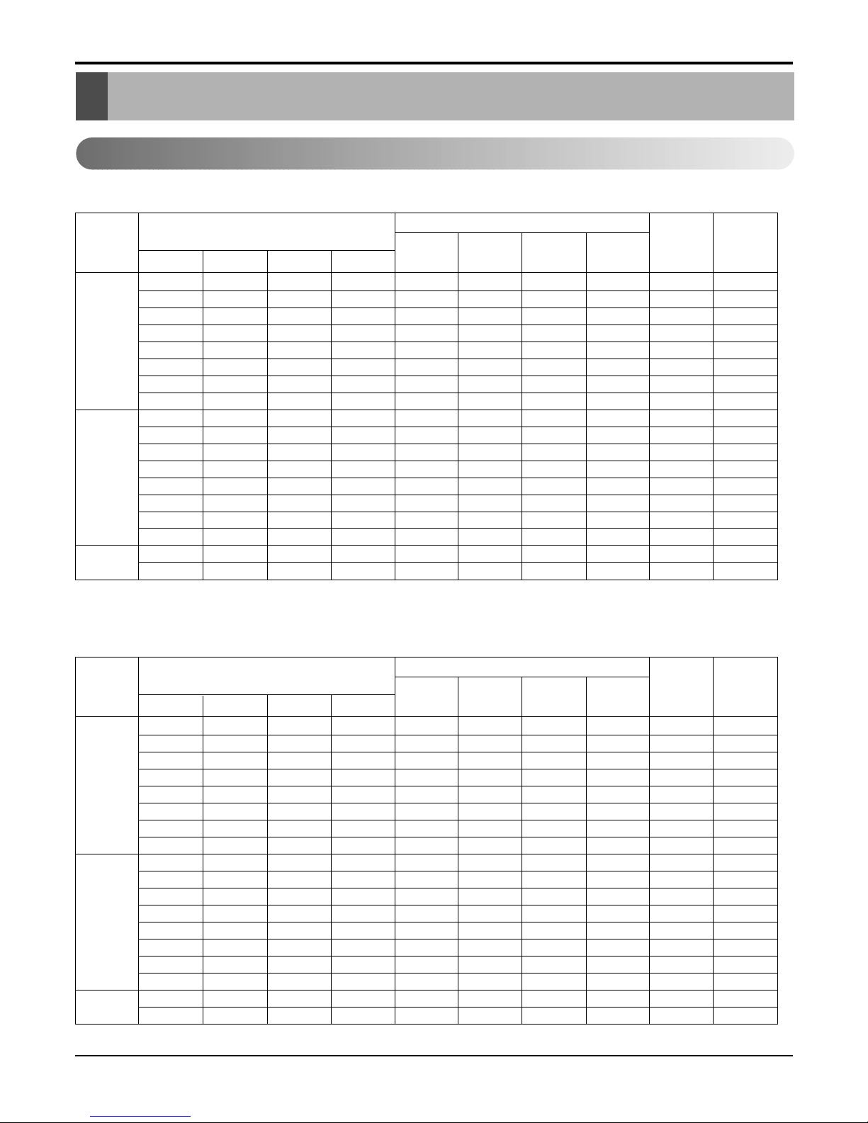
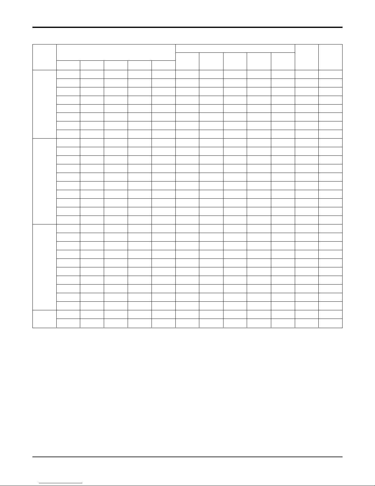
Indoor Unit Combination
Index(k Btu/h)
Capacity (Btu/h)
Input
(W)
Current
(A)
Unit-A Unit-B Unit-C Total
A B C Total
Operation
1 UNIT 12(S-RAC) 12 13000 13000 1460 6.8
12(DUCT) 12 12000 12000 1460 6.8
18(S-RAC) 18 18000 18000 2190 10.2
18(DUCT) 18 18000 18000 2190 10.2
24(S-RAC) 24 22000 22000 2600 12.1
24(DUCT) 24 24000 24000 2600 12.1
24(S-RAC) 24 22000 22000 2600 12.1
24(DUCT) 24 24000 24000 2600 12.1
2 UNIT 12(S-RAC) 12(S-RAC) 24 12500 12500 25000 2760 12.6
12(DUCT) 12(DUCT) 24 12000 12000 24000 2760 12.6
12(S-RAC) 24(S-RAC) 36 13000 22000 35000 4060 18.9
12(DUCT) 24(DUCT) 36 12000 24000 36000 4060 18.9
18(S-RAC) 24(S-RAC) 42 18000 22000 40000 4740 22.1
18(DUCT) 24(DUCT) 42 18000 24000 42000 4740 22.1
24(S-RAC) 24(S-RAC) 48 22000 22000 44000 5360 24.7
24(DUCT) 24(DUCT) 48 24000 24000 48000 5360 24.7
3 UNIT 12(S-RAC) 12(S-RAC) 24(S-RAC) 48 12500 12500 22000 47000 5360 24.7
12(DUCT) 12(DUCT) 24(DUCT) 48 12000 12000 24000 48000 5360 24.7
Indoor Unit Combination
Index(k Btu/h)
Capacity (Btu/h)
Input
(W)
Current
(A)
Unit-A Unit-B Unit-C Total
A B C Total
Operation
12 Multi Type Air Conditioner
Combination Table
Combination Table
1. L3UC(H)482FA0
Cooling
Heating
Service Manual 13
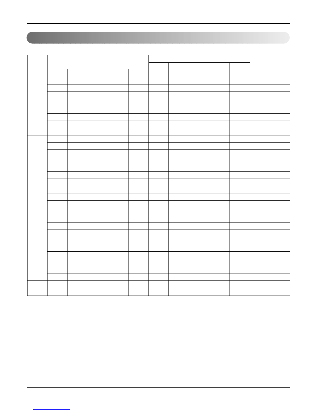
Combination Table
2. L3UC(H)602FA0
1 UNIT 12(S-RAC) 12 13000 13000 1460 6.8
12(DUCT) 12 12000 12000 1460 6.8
18(S-RAC) 18 18000 18000 2190 10.2
18(DUCT) 18 18000 18000 2190 10.2
24(S-RAC) 24 22000 22000 2600 12.1
24(DUCT) 24 24000 24000 2600 12.1
24(S-RAC) 24 22000 22000 2600 12.1
24(DUCT) 24 24000 24000 2600 12.1
2 UNIT 12(S-RAC) 12(S-RAC) 24 12500 12500 25000 2760 12.6
12(DUCT) 12(DUCT) 24 12000 12000 24000 2760 12.6
12(S-RAC) 24(S-RAC) 36 13000 22000 35000 4060 18.9
12(DUCT) 24(DUCT) 36 12000 24000 36000 4060 18.9
18(S-RAC) 18(S-RAC) 36 18000 18000 36000 4060 18.9
18(DUCT) 18(DUCT) 36 18000 18000 36000 4060 18.9
18(S-RAC) 24(S-RAC) 42 18000 22000 40000 4740 22.1
18(DUCT) 24(DUCT) 42 18000 24000 42000 4740 22.1
24(S-RAC) 24(S-RAC) 48 22000 22000 44000 5360 24.7
24(DUCT) 24(DUCT) 48 24000 24000 48000 5360 24.7
3 UNIT 12(S-RAC) 12(S-RAC) 12(S-RAC) 36 12500 12500 12500 37500 4060 18.9
12(DUCT) 12(DUCT) 12(DUCT) 36 12000 12000 12000 36000 4060 18.9
12(S-RAC) 12(S-RAC) 24(S-RAC) 48 12500 12500 22000 47000 5360 24.7
12(DUCT) 12(DUCT) 24(DUCT) 48 12000 12000 24000 48000 5360 24.7
12(S-RAC) 18(S-RAC) 24(S-RAC) 54 12500 18000 22000 52500 6030 27.8
12(DUCT) 18(DUCT) 24(DUCT) 54 12000 18000 24000 54000 6030 27.8
18(S-RAC) 18(S-RAC) 24(S-RAC) 60 18000 18000 22000 58000 6700 30.9
18(DUCT) 18(DUCT) 24(DUCT) 60 18000 18000 24000 60000 6700 30.9
12(S-RAC) 24(S-RAC) 24(S-RAC) 60 12500 22000 22000 56500 6700 30.9
12(DUCT) 24(DUCT) 24(DUCT) 60 12000 24000 24000 60000 6700 30.9
4 UNIT 12(S-RAC) 12(S-RAC) 12(S-RAC) 24(S-RAC) 60 12500 12500 13000 22000 60000 6700 30.9
12(DUCT) 12(DUCT) 12(DUCT) 24(DUCT) 60 12000 12000 12000 24000 60000 6700 30.9
Indoor Unit Combination
Index(k Btu/h)
Capacity (Btu/h)
Input
(W)
Current
(A)
Unit-A Unit-B Unit-C Unit-D Total
ABCDTotal
Operation
Cooling
Combination Table
14 Multi Type Air Conditioner
Heating
1 UNIT 12(S-RAC) 12 13000 13000 1460 6.8
12(DUCT) 12 12000 12000 1460 6.8
18(S-RAC) 18 18000 18000 2190 10.2
18(DUCT) 18 18000 18000 2190 10.2
24(S-RAC) 24 22000 22000 2600 12.1
24(DUCT) 24 24000 24000 2600 12.1
24(S-RAC) 24 22000 22000 2600 12.1
24(DUCT) 24 24000 24000 2600 12.1
2 UNIT 12(S-RAC) 12(S-RAC) 24 12500 12500 25000 2760 12.6
12(DUCT) 12(DUCT) 24 12000 12000 24000 2760 12.6
12(S-RAC) 24(S-RAC) 36 13000 22000 35000 4060 18.9
12(DUCT) 24(DUCT) 36 12000 24000 36000 4060 18.9
18(S-RAC) 18(S-RAC) 36 18000 18000 36000 4060 18.9
18(DUCT) 18(DUCT) 36 18000 18000 36000 4060 18.9
18(S-RAC) 24(S-RAC) 42 18000 22000 40000 4740 22.1
18(DUCT) 24(DUCT) 42 18000 24000 42000 4740 22.1
24(S-RAC) 24(S-RAC) 48 22000 22000 44000 5360 24.7
24(DUCT) 24(DUCT) 48 24000 24000 48000 5360 24.7
3 UNIT 12(S-RAC) 12(S-RAC) 12(S-RAC) 36 12500 12500 12500 37500 4060 18.9
12(DUCT) 12(DUCT) 12(DUCT) 36 12000 12000 12000 36000 4060 18.9
12(S-RAC) 12(S-RAC) 24(S-RAC) 48 12500 12500 22000 47000 5360 24.7
12(DUCT) 12(DUCT) 24(DUCT) 48 12000 12000 24000 48000 5360 24.7
12(S-RAC) 18(S-RAC) 24(S-RAC) 54 12500 18000 22000 52500 6030 27.8
12(DUCT) 18(DUCT) 24(DUCT) 54 12000 18000 24000 54000 6030 27.8
18(S-RAC) 18(S-RAC) 24(S-RAC) 60 18000 18000 22000 58000 6700 30.9
18(DUCT) 18(DUCT) 24(DUCT) 60 18000 18000 24000 60000 6700 30.9
12(S-RAC) 24(S-RAC) 24(S-RAC) 60 12500 22000 22000 56500 6700 30.9
12(DUCT) 24(DUCT) 24(DUCT) 60 12000 24000 24000 60000 6700 30.9
4 UNIT 12(S-RAC) 12(S-RAC) 12(S-RAC) 24(S-RAC) 60 12500 12500 13000 22000 60000 6700 30.9
12(DUCT) 12(DUCT) 12(DUCT) 24(DUCT) 60 12000 12000 12000 24000 60000 6700 30.9
Indoor Unit Combination
Index(k Btu/h)
Capacity (Btu/h)
Input
(W)
Current
(A)
Unit-A Unit-B Unit-C Unit-D Total
ABCDTotal
Operation
Service Manual 15
Dimensions
Dimensions
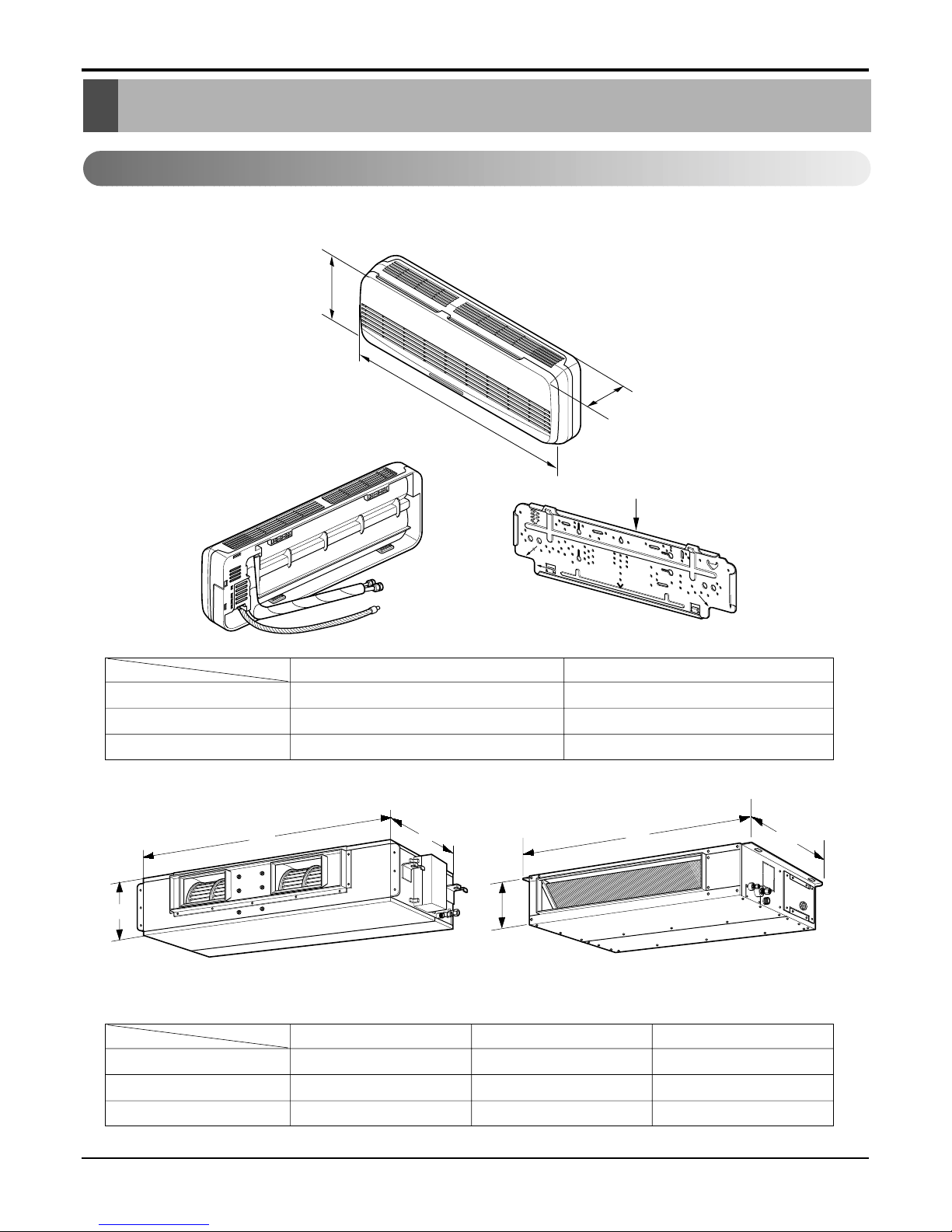
1. Indoor Unit
1. Split Type
2. Duct Type
Installation plate
D
H
W
W
H
D
BH BT/BT1
H
W
D
MODEL
DIM
W(mm) 708 1060 880
H(mm) 230 230 260
D(mm) 357 357 450
BT 12K BT1 18K BH 24K
MODEL
DIM
W(mm) 900 1080
H(mm) 285 314
D(mm) 156 182
SR 12K ST 18K/24K
16 Multi Type Air Conditioner
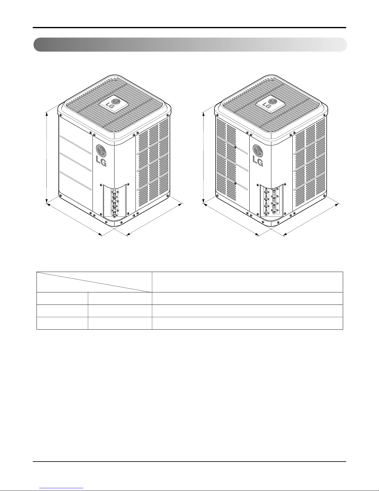
W mm 711
H mm 828
D mm 687
48K/60K Btu/h
MODEL
DIM
Dimensions
2. Outdoor Unit
H
W
D
H
W
D
48K 60K
Service Manual 17
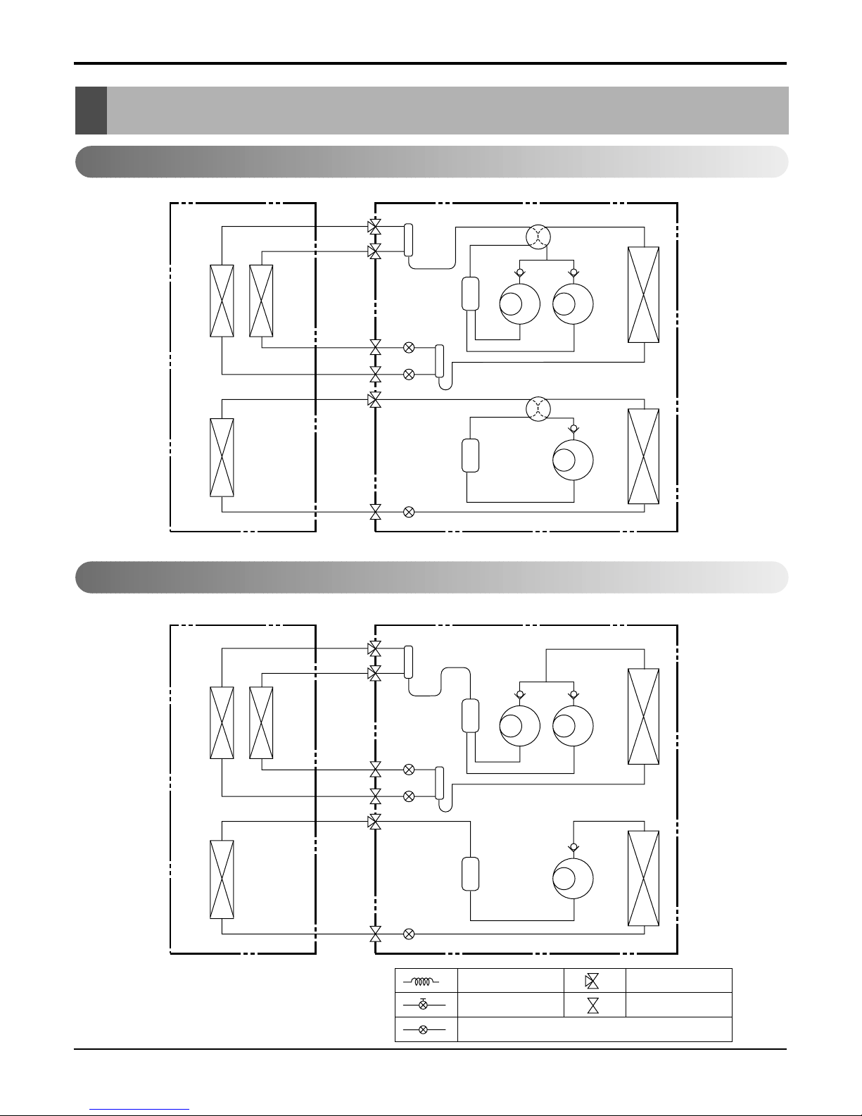
Refrigeration Cycle Diagram
ex)
Solenoid Valve
L.E.V
Capillary
3-Way Valve
2-Way Valve
Indoor Side Outdoor Side
B
A
4- WAY Valve
COMP
B
COMP
A
Accum.
C
4- WAY Valve
COMP
C
Accum.
Indoor Side Outdoor Side
B
A
COMP
B
COMP
A
Accum.
C
COMP
C
Accum.
Refrigeration Cycle Diagram
1. L3UH482FA0
2. L3UC482FA0
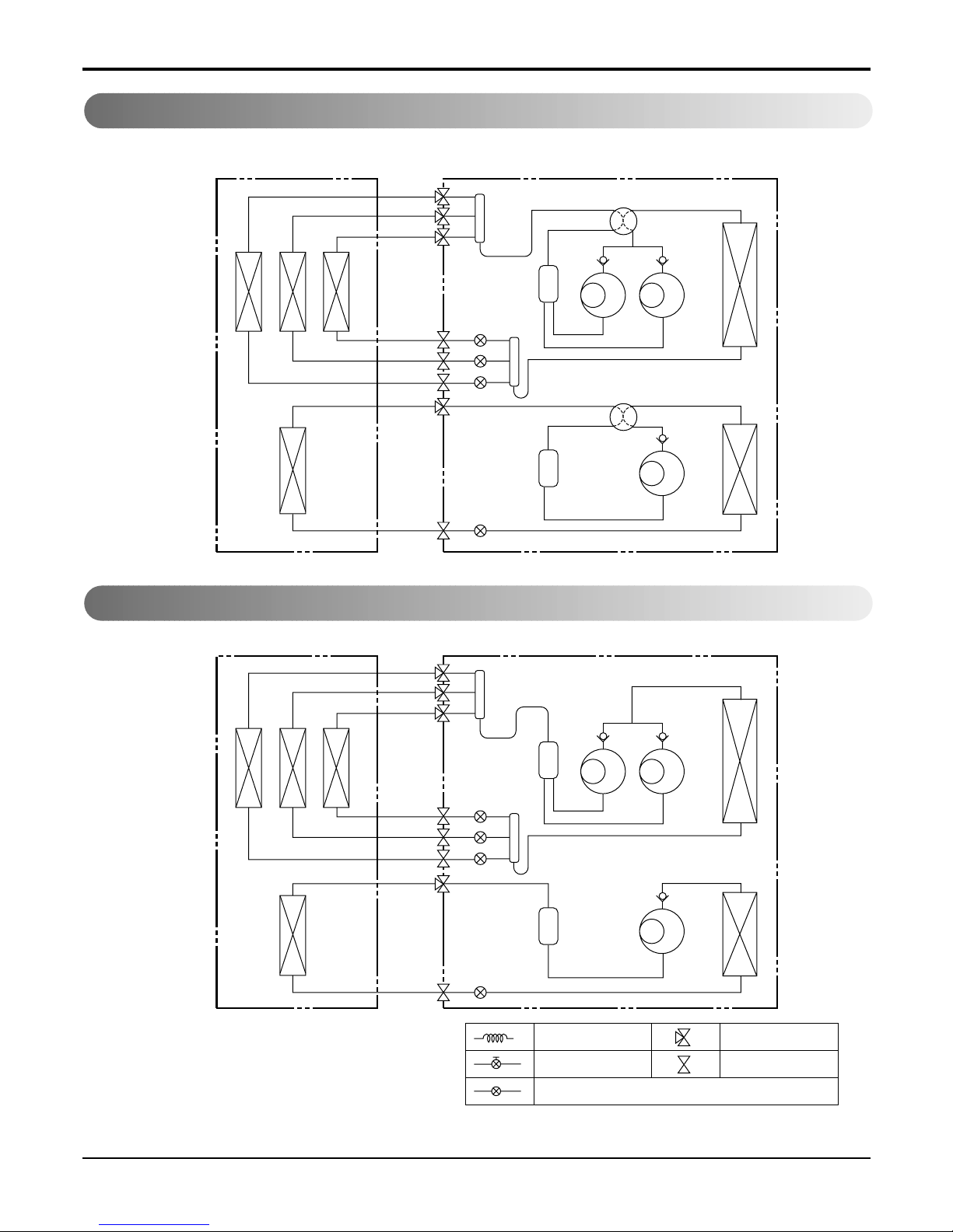
18 Multi Type Air Conditioner
Refrigeration Cycle Diagram
3. A4UH602FA0
4. A4UC602FA0
ex)
Solenoid Valve
L.E.V
Capillary
3-Way Valve
2-Way Valve
Indoor Side Outdoor Side
B
A
4- WAY Valve
COMP
B
COMP
A
Accum.
C
D
4- WAY Valve
COMP
C
Accum.
Indoor Side Outdoor Side
B
A
COMP
B
COMP
A
Accum.
C
D
COMP
C
Accum.
Service Manual 19
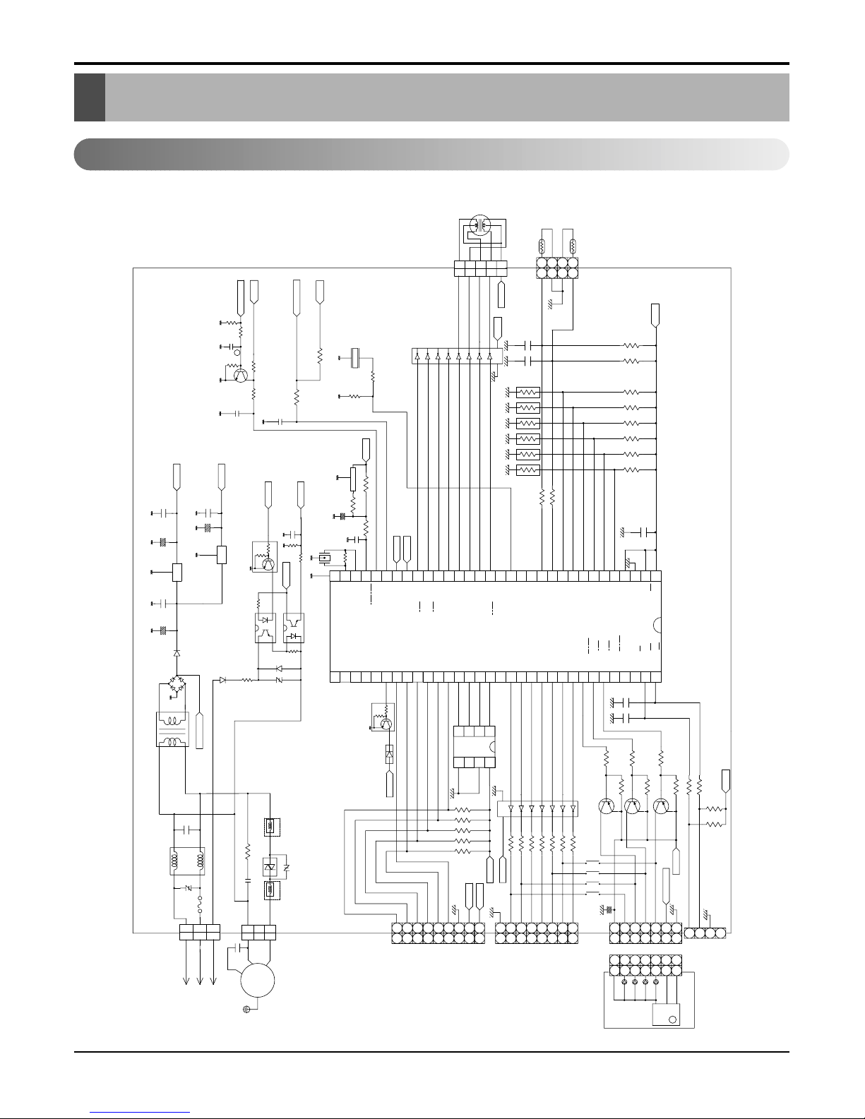
Schematic Diagram
Schematic Diagram
Electronic Control Device
FREQUENCY
6171AQ3124C
POWER TRANS
R02A,4.7K
10uF/50V
R05C
4.7K
R04C,10K
FREQUENCY
R03C,20K
M
C02C
50V
0.015
KTC3198Y
Q01C
25V
C01C
0.01
DC 12V
DC 5V
R02E,20
R02C,4.7K
REMOCON
5V
5V
R02L,10K
BZ01E
18
17
KID65084AP
1
IC01M
2
C01L
50V
680pF
R01C,1K
R01L,1K
TX
RX
R01E,1K
IC01A
5V
KIA7036P
R05K
680
Q01K
0.1
0.01
25V 25V
50V
IC02D
7805
470uF
KRC102M
C03D
0.01
C04D
25V 16V
+
C06D
+
O
C05D
IC01D
470uF
O
7812
I
C02D
I
35V
C01D
2200uF
1SR139-600
+
D01D
1SR139-600
D02D-05D
D02K
25K,3W,1%
1SR139-600
R44/EC0
R45/EC2
R42/INT2
R41/INT1
R40/INT0
R43/INT3
R04K
10K
R01K
0.001
25V
CST-8.00MTW
OSC01B
C01K
DC 5V
32
R02K,1K
VSS
R03A,100
C02A
+
C01A
0.01
50V
R01A,1K
TX
RX
27
293028
31
R01B,1M
XIN
RESET'
XOUT
252623
24
R27
1SR139-600
D01K
R03K
IC02K(TLP627)
241
1K
314
IC01K(TLP621)
3 2
A16
14D271
ZNR01K
33
R20
R17
R16
R24
R25
R23
R22
R26
A11
A13
A14
A12
A15
R21
A7
A6
A10
A8
38
363537
34
Q01M
KRC107M
403941
42
YL
RD
OR
BL
PK
UP/DOWN
STEP MOTOR
ROOM-TH
PIPE-TH
R03H,1K
R01H,1K
0.01
5
44
5
DC 12V
CN-U/D
223311
161514
13
345
6
12
10
11
DC12V
50V
798
224433
11
CN-TH
C01H C02H
OP5
XXXK
OP6
XXXK
OP4
XXXK
OP2
XXXK
OP3
XXXK
OP1
XXXK
5V
R02H
12.1K
1%
R04H1%6.2K
R13H
12.1K
R15H
12.1K
R16H
12.1K
R14H
12.1K
R11H
12.1K
R12H
12.1K
C01F,0.01/50V
C02F,0.01/50V
R34
60
SYNC
5
R67/AN7
R66/AN6
R57/PWM1
R55/BUZ
R54/WDTO
R52/Sclk
R53/Srdy
R56/PWM0
R46/T10
R47/T30
R51/Sout
R62/AN2
R60/AN0
R61/AN1
R63/AN3
R64/AN4
R65/AN5
14
212220
19
R50/Sin
171816
1510131211
6 9 8
7
R05
51
D5
R10
R07
R06
R14
R15
R13
R12
A4A5A3
A2
R11A1
D7D6A0
444345
46
Q
D
484749
50
S
C
R35
R00
R37
R04
R03
R02
R36
R01D1
D4D3D2
HALT
BRKD0BRQ
555253
5459565758
MICOM
GMS81516
C01M
50V
0.01
1
2 4 3
Vdd
MP
AVref
AVss
R30
R33
R32
R/W
R31Wt
C
RD
64
636162
NEUTRAL
0.1, AC275V
C01J
ZNR01J
FUSE
INR14D471K
250V/T2A
SVC561D-14A
NF01J
LIVE
2
1
2
CN-POWER
1
1
3
1
COM
3
R01M,120,1/2W
NF01M
DC 12V
SSR-MOTOR
INR14D471K
C01M,0.1,AC275V
SSR-MOTOR
NF01M
ZNR01M
3
2
3
CN-FAN
2
CN-SUB
897
6
897
6
MOTOR
INDOOR
FAN
4
177
Q11G
R07G,220
R01G,220
R06G,220
R03G,220
R05G,220
R04G,220
R02G,220
11
6
4
3
5
Vss6ORG
EEPROM
1
2
8
VCC7DU
R01T,10K
R03T,10K
R02T,10K
8
7
9
10
R11G,,6.8K
254
3
151213
14
KRA1270Y
IC02M
KID65004AP
1
16
66
DC 12V
DC 5V
R05T,10K
R04T,10K
DC 5V
DC 5V
453
2
453
2
187
187
254
3
2
543
1
220uF
10V
CN-DISP1
1
CN-DISP2
R02F,10K
R03F,1K
R01F,1K
R14G,6.8K
R16G,6.8K
R12G,6.8K
R13G,6.8K
R15G,6.8K
KTA1270Y
Q12G
KTA1270Y
Q13G
5V
R04F,10K
C02L
DC 5V
REMOCON
3
4653
2
53
4
6
5
4
3
2
17
62
1
SLIDE S/W
1
2
REMO
1
PRE AMP
TFMS-
LED4
LED1
LED3
LED2
324
5
2380B
Vcc
ASSY
DISPLAY
7
6
GND
Vout
1. Indoor Unit
1) Split Type
20 Multi Type Air Conditioner
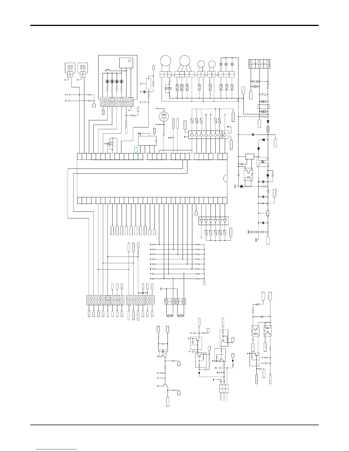
Schematic Diagram
2) Duct Type
11
4423
2
3
P12(INT2/TC1)
P20(INT5/STOP)
223311
11
SW
Force
P32
LOUVER
FLOAT
LED4
P35
P34
P33
8.00MHZ
OSC01B
5
VSS
XIN
LED3
LED2
LED1
XOUT
P31
P30
VSS
XOUT
XIN
NC
RESET
NC
S
Q
4
GND
P21(XTIN)
RESET
P22(XTOUT)
TEST
KIA7036P
1
22
33
11
2
3
1
3
1
3
1
3
1
3
33
55
11
REMO
FREQ
PHASE
876
VCC
DU
ORG
EERROM
1
QCD
C
2
S
D
3
P15(TC2)
P16
P17
P14(PPG)
P13(DVO)
P10(INT0)
P11(INT1)
P07
P06
P05
LOW
HIGH
STEP M5
MED
LOUVER
D/PUMP
STEP M2
STEP M3
P04
P03
P01
P00
P02
P76
P77
NC
CSO
CSI
NC
NC
NC
SB1
SB2
SO1/PLC
SB0
CC RX
CC TX
SI1/MULTI TX
SCK1/MULTI RX
(SO1)/P44
(SCK2)/P45
(SI2)/P46
(SCK)/P42
(SI1)/P43
(PWM/PDO)/P52
(SO2)/P47
(INT3/TC3)/P50
(INT4/TC4)/P51
P53
유선_RX
(AIN7)/P67
OPTION5
OPTION4
OPTION3
OPTION2
PIPE TH
ROOM TH
OPTION 1
SB3
(AIN2)/P62
VASS
VARF
(AIN0)/P60
(AIN1)/P61
P54
(AIN3)/P63
(AIN5)/P65
(AIN6)/P66
(AIN4)/P64
OUTFAN
4WAY
HEATER
A/C
COMP
STEP M4
OPTION6
P71
VDD
P70
P72
P73
P75
P74
유선_TX
CN-REMO
123
123
Multi_TX
Multi_RX
681
C05D
IC02D(TLP521)
470uF/35V
103/250VA
C04D
5V
DISPLAY
PRE AMP
TFMS-2380B
LED4
LED3
LED2
Vcc
GND
Vout
LED1
77
6
5
4
6
5
4
11
3
2
3
2
5V
29
323130
REMO
26282725242123
221920
3,7,8
NF01M
5V
+
ZNR01M
NF01M
SSR
8
5V
DC 12V
REMO
50/60Hz
13
16
1718151412
11
9
10
DC 12V
STEP M
STEP M
STEP M
DC 12V
IC02M
KID65004AF
5
6
7
3
4
103
1
2
100nF
C02J
275V
3
1
3
1
2 2
M_RTX
275V
AC_L
C03J
10nF
275V
3
100nF
C01J
NF
4
ZNR01J
INR14D561K
T3.15A,3A
250V/
22mH/3A
1
NF01J
2
DC310V
ZD01D
P6KE200A
NTC01D
10D-9
C01D
10uF/
400V
AC_N
1N4007
1M,1/2W
R01J
D01D
D03D
C03D
UF4005
TNY255P
IC01D
5
TNY
255P
2
S
1
4
D02D
3
D
BP
EN
4,5
UF5402
S/Trans
1
6,7
GND
3
GND
3
CN_ZONE
36
33343539373840
4144424345
46
7
8
Multi_RX
Multi_TX
5V
12V
5V
6
5
2
4
3
GND
6
1
4
5
CS0
7
8
CS1
6
5
SCK1
SI1
2
4
3
SO1
12V
5V
PLC_SEL
Multi_RX
Multi_TX
6
1
GND
4
5
CN-PIPE
CN-ROOM
CN_M C
ZD02D
57
52
484947
5051535455
5660585961
62
11V
64
63
STEP M
KID65004AF
IC02M
DC 12V
12V
5V
1
2
1 3 1 3
82K/3W
R15K
104
C08D
3.3uH
R04D
R03D
150
C06D
39
330uF/35V
C07D
12V
L01D
103/1KV
223/1KV
G
C12D
C11D
103
C10D
220uF/50V
C09D
IC03D
7805
KID78L05BP
I O
5V
M_RTX
1SR139-400
D12K
M_RTX
1SR139-400
D11K
1.5K
R13K
DC 5V
1
2
12V
5V
1 31 3
R14K
1K
IC12K(TLP627)
14
3
4
1
2
IC11K(TLP621)
23
DC 5V
R12K,1K
C11K
102
R11K
10K
DC 5V
10K
R16K
IC01M
KID65004AF
3.6V
C01A
CN-DISP
5V
CN-LOUVER
CN-FLOAT
103
C02F
R02F
1K
103
C01F
R01F
1K
1K
R04L
R05L
R06L
1K
1K
102
R03L
1K
3.3uF
/50V
1.0M
R01B
1K
R02L
R01L
10K
R02A
IC01A
FAN
MOTOR
CN-MOTOR2
FAN
壤
MOTOR
R01A 1K
C02A
10K
RY-M
RY-H
RY-L
CN-D/PUMP
Drain
Motor
Louver
Motor
CN-LOUVER
CN-MOTOR1
RY-OUTFAN
RY-4WAY
RY-HEATER
CN-OUT
RY-LOUV
RY-D/PUMP
RY-4WAY
RY-HEATER
RY-OUTFAN
C02L
BZ01E
1K
R01E
R02E
20
681
RY-COMP
NEUTRAL
SIGNAL
CN-POWER
LIVE
유선_TX
유선_RX
S_B0
중앙_RX
중앙_TX
S_B2
S_B1
R01U
10K
103
C02U
1K
AC_N
200K/2W
R01C
AC_L
R02C
C01K
102
5V
1K
R01K
R05C
C01C
103
1K
C03K
102
DAN212K
KRC104M
R03C
10K
IC01C
5V
R04C
4.7K
C02K
Q02K
102
12V
Q04K
KRA104M
Q01C
10K
R06C
5V
50/60Hz
D02K
5V
GND
S_B3
5V
OR1OR4OR6 OR5 OR2OR3
103
C01H
103
C02H
103
C01U
12.1K
R03H
1%
12.1K
R08H
1%
12.1K
R07H
1%
12.1K
R06H
1%
12.1K
R04H
1%
12.1K
R05H
1%
5V
6.2K
R02H
1%
1%
12.1K
R01H
Q11K
KRA104M
Q01K
5V
KRC104M
C05K
C06K
103
DAN212K 100nH
Q03K
KRC104M
12V
4.7K
104
C04K
R02K
D01K
L01K
L02K
L03K
GND
DC12V
Signal
TX
RX
 Loading...