

Lg Lmh1017cvw, Lmh1017cvst Service Manual

Website: http://us.lgservice.com
MICROWAVE OVEN
SERVICE MANUAL
MODEL: LMH1017CVW
CAUTION
BEFORE SERVICING THE UNIT, READ THE SAFETY PRECAUTIONS IN THIS MANUAL.
P/NO : 3828W5S6006
LMH1017CVST
May, 2004
Printed in Korea

SAFETY PRECAUTIONS
This device is to be serviced only by properly qualified service personnel.
Consult the service manual for proper service procedures to assure continued safety operation and for precautions to be
taken to avoid possible exposure to excessive microwave energy.
PRECAUTIONS TO BE OBSERVED BEFORE AND
DURING SERVICING TO AVOID POSSIBLE
EXPOSURE TO EXCESSIVE MICROWAVE ENERGY
A) Do not operate or allow the oven to be operated with the door open.
B) Make the following safety checks on all ovens to be serviced before activating the magnetron or other
microwave source, and make repairs as necessary; (1) interlock operation, (2) proper door closing, (3)
seal and sealing surfaces (arcing, wear, and other damage), (4) damage to or loosening of hinges and
latches, (5) evidence of dropping or abuse.
C) Before turning on microwave power for any service test or inspection within the microwave generating
compartments, check the magnetron, wave guide or transmission line, and cavity for proper alignment,
integrity, and connections.
D) Any defective or misadjusted components in the interlock, monitor, door seal, and microwave generation
and transmission systems shall be repaired, replaced, or adjusted by procedures described in this manual
before the oven is released to the owner.
E) A microwave leakage check to verify compliance with the Federal Performance Standard should be
performed on each oven prior to release to the owner.
CAUTION
MICROWAVE RADIATION
DO NOT BECOME EXPOSED TO RADIATION FROM THE MICROWAVE GENERATOR
OR OTHER PARTS CONDUCTING MICROWAVE ENERGY.

CONTENTS
(Page)
SAFETY PRECAUTIONS
SPECIFICATIONS
CAUTIONS
--------------------------------------------------------------------------------------------------------------
INSTALLATION
-----------------------------------------------------------------------------------------------------
--------------------------------------------------------------------------------------------------------
OPERATING INSTRUCTIONS
FEATURES
CONTROL PANEL
OPERATING SEQUENCE
SCHEMATIC DIAGRAM (I)
SCHEMATIC DIAGRAM (II)
CIRCUIT DESCRIPTION
-----------------------------------------------------------------------------------------------------------------------
SERVICE INFORMATION
TOOLS AND MEASURING INSTRUMENTS
MICROWAVE LEAKAGE TEST
---------------------------------------------------------------------
------------------------------------------------------------------------------------
-------------------------------------------------------------------------------------------------------------
---------------------------------------------------------------------------------------------------
--------------------------------------------------------------------------------------------------
-------------------------------------------------------------------------------------------------
-----------------------------------------------------------------------------------------------------
------------------------------------------------------------------------------------------
--------------------------------------------------------------------------------------------
Inside front cover
1-1
2-1
3-1
4-1
4-1
4-1
4-2
4-4
4-5
4-6
5-1
--------------------------------------------------------------------------
5-1
5-1
MEASUREMENT OF MICROWAVE POWER OUTPUT
DISASSEMBLY AND ADJUSTMENT
INTERLOCK CONTINUITY TEST
COMPONENT TEST PROCEDURE
TROUBLE SHOOTING
EXPLODED VIEW
-----------------------------------------------------------------------------------------------------
----------------------------------------------------------------------------------------------------
REPLACEMENT PARTS LIST
------------------------------------------------------------------------------------
-----------------------------------------------------------------------------------------
--------------------------------------------------------------------------------------
------------------------------------------------------------------------------------
-----------------------------------------------------------
5-3
5-3
5-8
5-9
5-13
6-1
7-1
SPECIFICATIONS
ITEM
MODEL
Power Requiremen
Power Output
Microwave Frequency
Magnetron
Timer
Outside Dimensions
Cavity Dimensions
Net Weight
Shipping weight
Control Complement
DESCRIPTION
LMH1017CVW / LMH1017CVST
120 V AC, 60 Hz
Single phase, 3 wire grounded
Microwave 1,400W
Convection 1,350W
Combination 1,500W
1,000 Watts full microwave power (IEC60705)
2,450 MHz
2M246-050GF
0 ~ 99 min. 99 sec.
201/
8”(W) x 12
14”(W) x 8
1
/
4”(H) x 19
1
/
2”(H) x 13
42 lbs (approx.)
46 lbs (approx.)
Touch Control System
Clock : 1:00 - 12:59
13
/
5
/
16”(D)
16”(D)
Microwave Power for Variable Cooking
Power level
HIGH .................................... Full power throughout the cooking time
9 (Saute)
7 (Med.-High)
5 (Med.-Low)
3 (Low)
1 (Warm)
...............................
.......................
........................
.................................
..............................
approx. 90% of Full power, 8 (Reheat)
approx. 70%, 6 (Medium)
approx. 50%, 4 (Defrost)
approx. 30%, 2 (Simmer)
approx. 10%
• Convection - 100°F and 225°F to 450°F
• Combination
Accessories
Owner's manual
Glass Tray
Rotating Ring
Metal Rack
Metal Tray
This microwave oven is designed for household use only.
It is not recommended for commercial purposes.
..........
approx. 80%
.........
approx. 60%
..........
approx. 40%
.........
approx. 20%
1-1
CAUTIONS
Unlike other appliances, the microwave oven is
high-voltage and high-current equipment.
Though it is free from danger in ordinary use,
extreme care should be taken during repair.
• DO NOT operate on a 2-wire extension cord during
repair and use.
• NEVER TOUCH any oven components or wiring during
operation.
• BEFORE TOUCHING any parts of the oven, always
remove the power plug from the outlet.
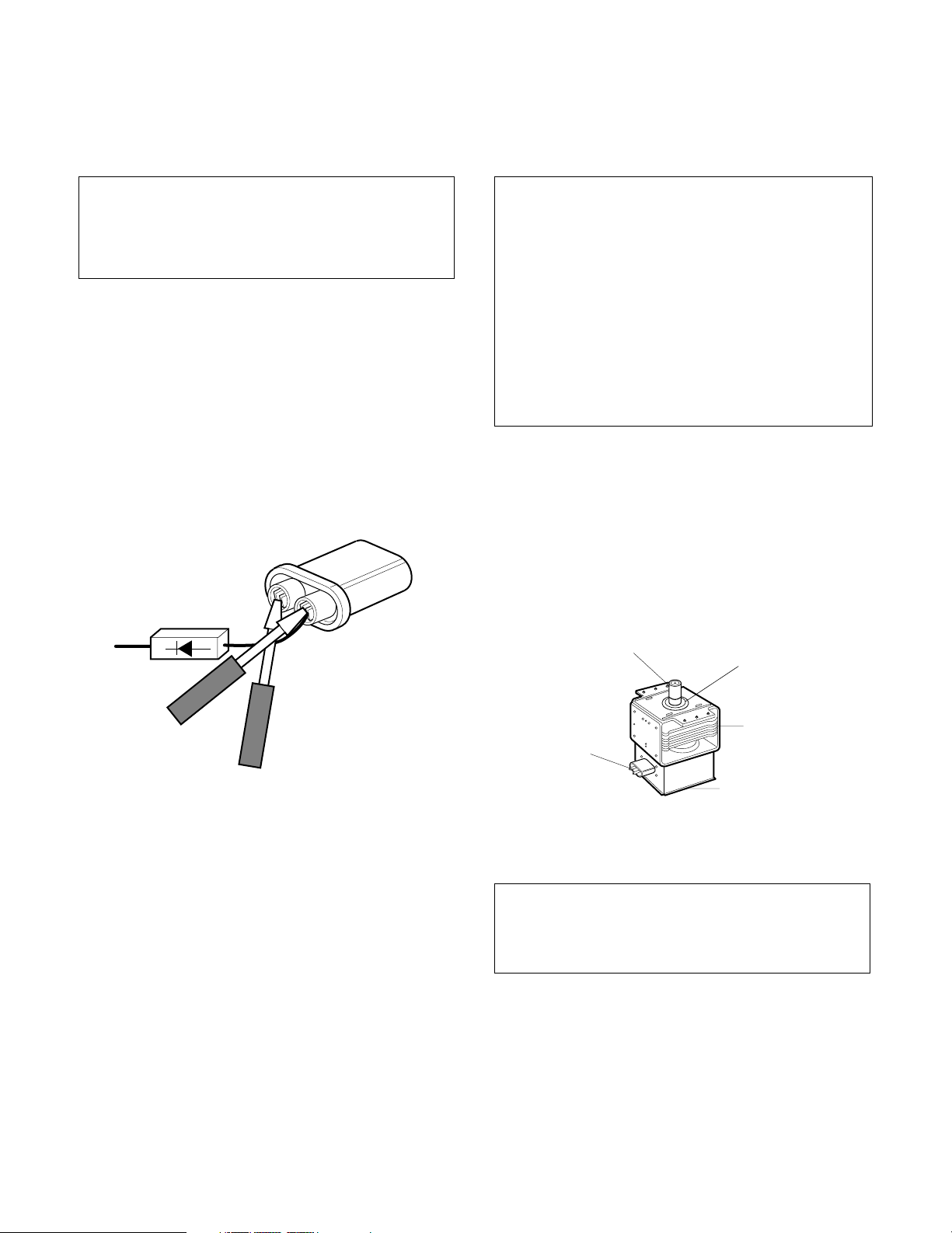
• For about 30 seconds after the oven stops, an electric
charge remains in the high voltage capacitor. When
replacing or checking, you must discharge the high
voltage capacitor by shorting across the two terminals
with an insulated screwdriver.
MICROWAVE RADIATION
Personnel should not be exposed to the
microwave energy which may radiate from the
magnetron or other microwave generating
device if it is improperly used or connected.
All input and output microwave connections,
waveguide, flange, and gasket must be
secured never operate the device without a
microwave energy absorbing load attached.
Never look into an open waveguide or antenna
while the device is energized.
• Proper operation of the microwave oven requires that
the magnetron be assembled to the waveguide and
cavity. Never operate the magnetron unless it is
properly installed.
• Be sure that the magnetron gasket is properly
installed around the dome of the tube whenever
installing the magnetron.
• Remove your watches whenever working close to or
replacing the Magnetron.
• DO NOT touch any parts of the control panel circuit. A
resulting static electric discharge may damage this
P.C.B.
• NEVER operate the oven with no load.
• NEVER injure the door seal and front plate of the oven
cavity.
• NEVER put iron tools on the magnetron.
• NEVER put anything into the latch hole and the
interlock switches area.
ANTENNA
GASKET
COOLING FIN
FILAMENT
TERMINALS
MAGNETRON
CHASSIS GROUND
MAGNETRON
THE OVEN IS TO BE SERVICED ONLY
BY PROPERLY QUALIFIED SERVICE
PERSONNEL.
2-1
INSTALLATION
BEFORE YOU BEGIN, READ THE FOLLOWING INSTRUCTIONS COMPLETELY AND CAREFULLY.
INSTALLING
1. Empty the microwave oven and clean inside it with
a soft, damp cloth. Check for damage such as
misaligned door, damage around the door, dents
inside the cavity, or on the exterior.
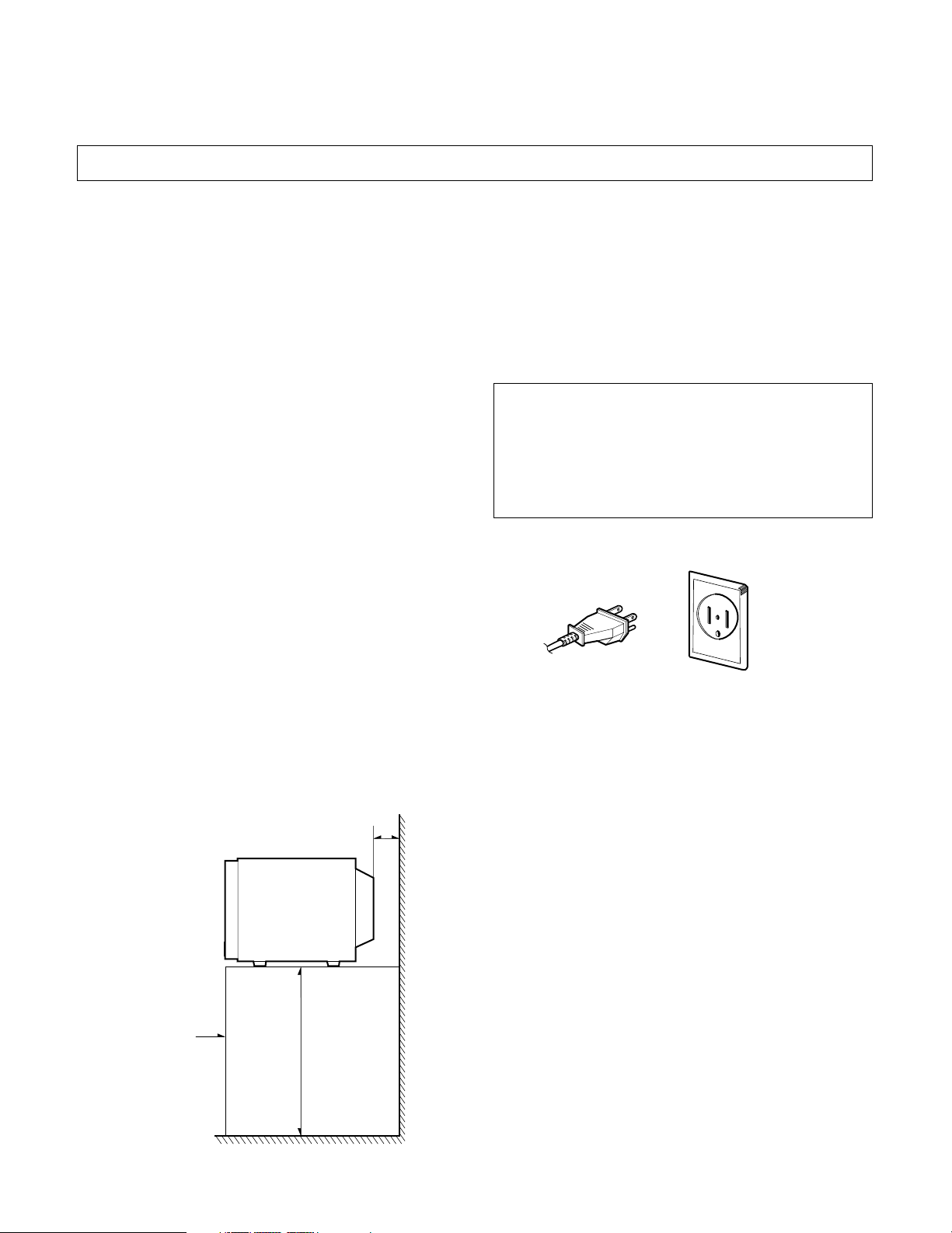
2. Put the oven on a counter, table, or shelf at least
100cm (39.4 inches) from floor that is strong
enough to hold the oven and the food and utensils
you put in it. (The control panel side of the oven is
the heavy side. Use care when handling.)
3. Do not block the vent and the air intake openings.
Blocking vent or air intake openings can cause
damage to the oven and poor cooking results.
Make sure the microwave oven legs are in place to
ensure proper air flow.
4. The oven should not be installed in any area where
heat and steam are generated, because they may
damage the electronic or mechanical parts of the unit.
Do not install the oven next to a conventional
surface unit or above a conventional wall oven.
5. Use microwave oven in an ambient temperature
less than 104°F(40°C).
6. Place the microwave oven on a sturdy and flat
surface at least 5 cm(2 inches) from the wall.
GROUNDING INSTRUCTIONS
For personal safety, this appliance must be fully
grounded at all times.
In the event of an electrical short circuit, grounding
reduces the risk of electrical shock.
The plug must be plugged into an outlet that is
properly installed and grounded.
WARNING
Improper use of the grounding plug can result in a
risk of electric shock.
Do not, under any circumstances, cut or remove
the third ground prong from the power cord plug.
PREFERRED METHOD
ENSURE PROPER GROUND
EXISTS BEFORE USE
7. Place the microwave oven as far away as possible
from TV, RADIO, COMPUTER, etc., to prevent
interference.
5cm
Counter,
100cm
table, shelf
3-1
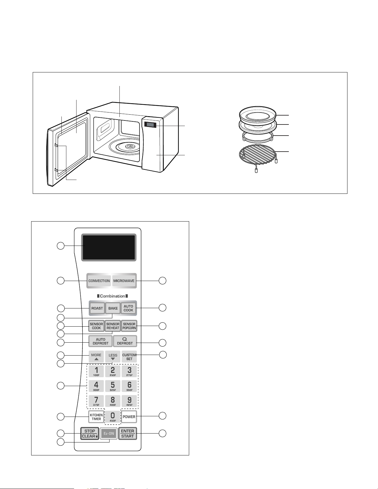
FEATURES
Oven Front Plate
Window Door Screen
Door Seal
Safety Interlock
System
Control Panel
Display Window
Metal Tray
Glass Turntable
Rotating Ring
Metal Rack
CONTROL PANEL
1
2
4
5
7
8
10
12
13
15
16
18
19
OPERATING INSTRUCTIONS
1. DISPLAY. The display includes a clock and indicators that tell you
time of day, cooking time settings, and cooking functions selected.
2. CONVECTION. Touch this button to cook foods on convection
mode.
3. MICROWAVE. Touch this button to cook foods on microwave
mode, and to set cooking time and power level.
4. ROAST. Touch this button to roast foods on combination mode.
5. BAKE. Touch this button to bake foods on combination mode.
6. AUTO COOK. Touch this pad to cook foods automatically on
3
6
9
11
14
17
20
combination mode.
7. SENSOR COOK. Touch this button to cook most of your favorite
foods without entering cooking time or power level.
8. SENSOR REHEAT. Touch this button to reheat foods without
entering cooking time and power level.
9. SENSOR POPCORN. Touch this button to cook popcorn
automatically.
10. AUTO DEFROST. Meat, Poultry, Fish, Bread. Touch this pad to
select food type and defrost food by weight.
11. Q DEFROST. This pad provides you with the rapid defrosting
method for 1.0 pounds frozen foods.
12. MORE. Touch this pad to add ten seconds of cooking time each
time you press it.
13. LESS. Touch this pad to subtract ten seconds of cooking time each
time you press it.
14. CUSTOM SET. Touch this button to change the oven's default
settings for sound, clock, scroll speed, and Lbs/kg.
15. NUMBER. Touch number pads to enter cooking time, power level,
quantities, or weights.
16. KITCHEN TIMER. Touch this button to use as a kitchen timer
without operating the oven.
17. POWER. Touch this pad to set a cook power.
18. STOP/CLEAR: Touch this button to stop the oven or to clear
entries and to engage or disengage the child lock. See page 12.
19. Ez-ON: You can extend cooking time in multiples of 30 seconds by
repeatedly touching this pad during cooking.
20. ENTER/START. Touch this button to start entries.
4-1
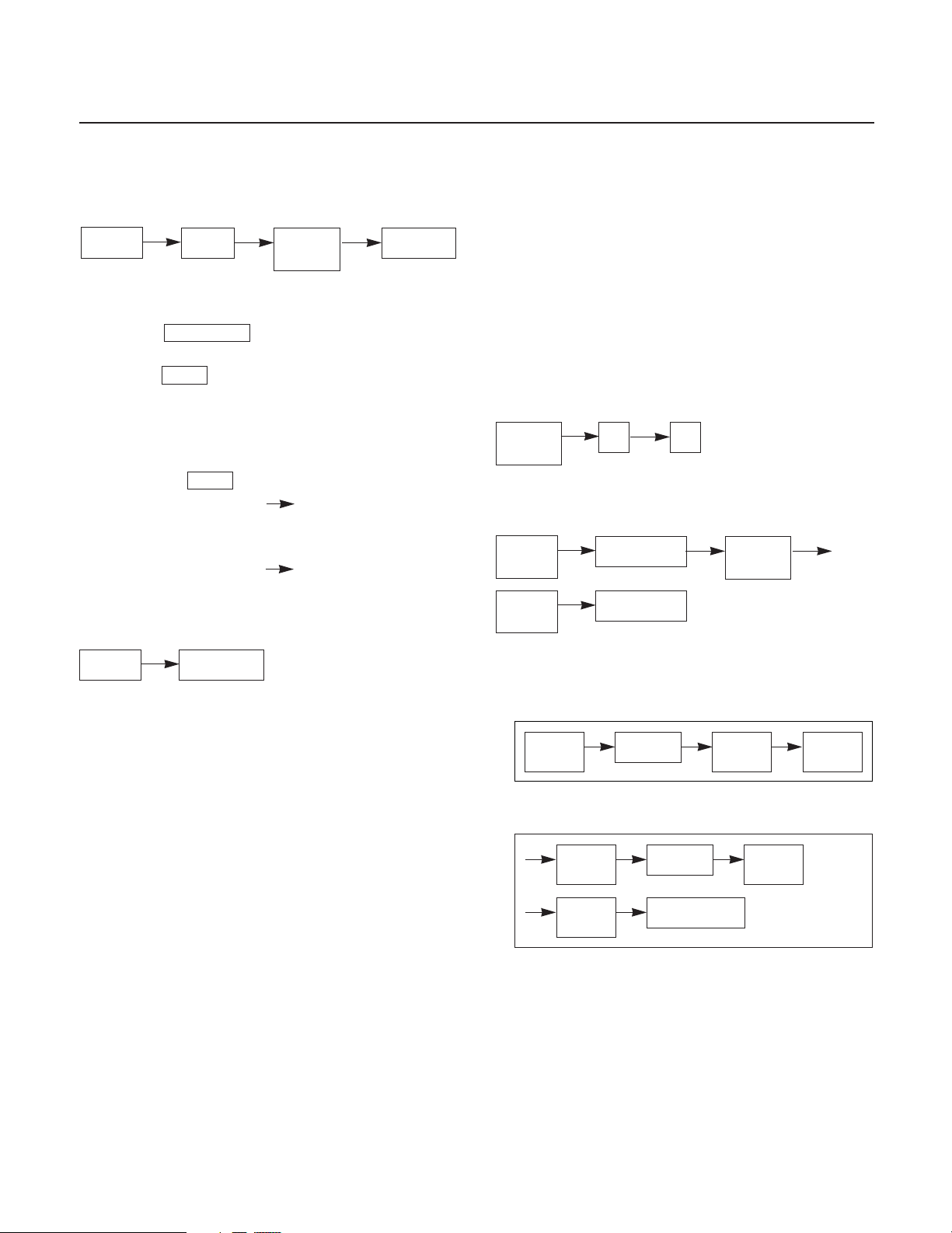
OPERATING SEQUENCE
The following is a description of component functions
during oven operation.
1. SETTING THE CLOCK
Clear
Clock
Desired
clock
Start/Pause
2. CANCEL FUNCTION
1) Touch Start/Pause pad to start oven or pause the
oven temporarily during cooking.
2) Touch Clear pad to cancel a program during
cooking or Erase during programming.
3. CHILD LOCK
TO SET CHILD LOCK
• Touch the Clear pad
• Touch and hold 0 pad LOCKED appear on
the display.
TO CANCEL CHILD LOCK
• Touch and hold 0 pad LOCKED disappear
in the display.
4. EZ ON
5. MORE / LESS
This pad is to be used as a temperature selection
pad in convection mode and cook time adjustment
pad in the microwave mode.
6. CUSTOM SET
You can select Sound Control, Clock On/Off,
Scroll, Speed, LBS°F/KG°C, Demo On/Off, and
English/Spanish.
• To turn off the clock.
Custom
Set
2 2
7. TIMED COOKING
Cook
Time
Power
Level
Number
Start/Pause
Cook
Power
Clear
EZ On
8. MULTI-STAGE COOKING
1ST STAGE
Cook
Time
2ND STAGE
Cook
Time
Power
Level
Number
Number
Start/Pause
Cook
Power
Power
Level
Cook
Power
4-2
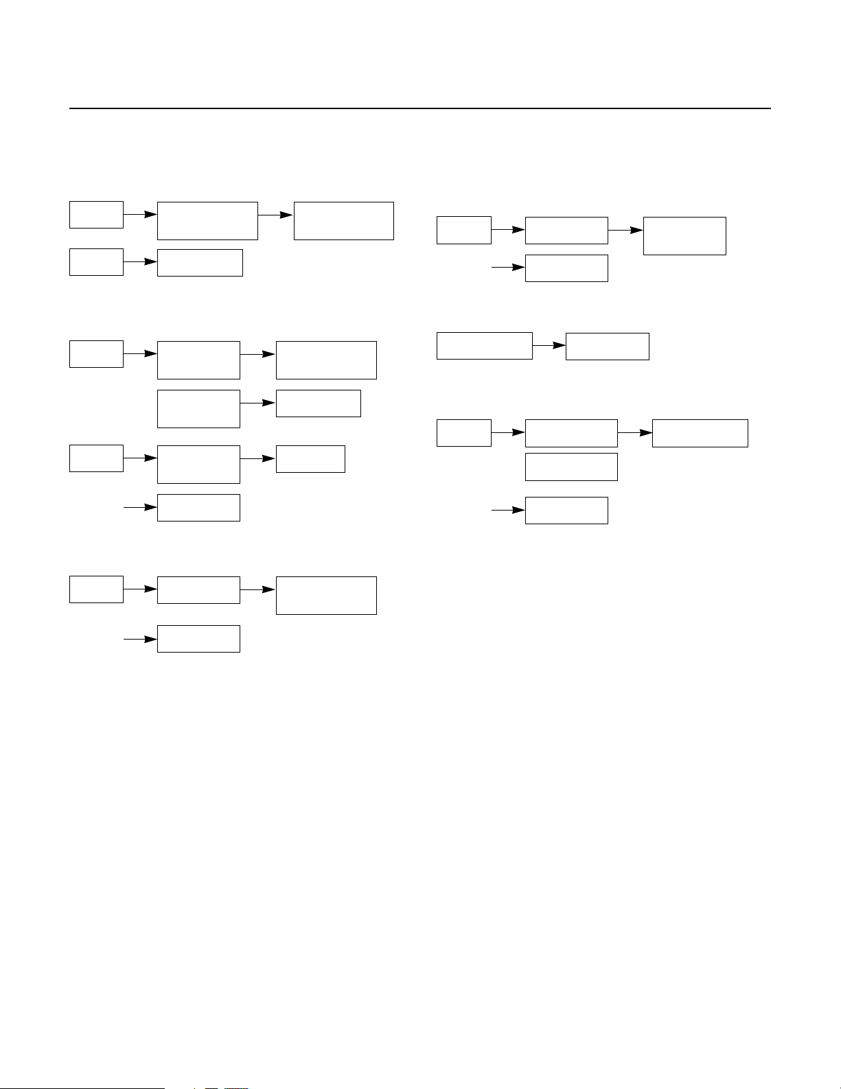
OPERATING SEQUENCE
9. SENSOR TOUCH
Clear
Clear
10. DEFROST AUTO/TIME
Clear
Clear
11. Q-DEFROST
Sensor Cook/
Reheat
Popcorn
Auto/Time
Defrost
Enter the
Weight
Auto/Time
Defrost
Start/Pause
Select Recipe
Categories
Select Recipe
Categories
Start/Pause
Number
12. CONVECTION
TO PREHEAT
Clear
TO COOK(After preheating)
Cooking Time
Convection
Start/Pause
Start/Pause
13. COMBINATION
Clear
Combi-Roast
Combi-Bake
Start/Pause
Select
Temperature
Cooking Time
Clear
Q-Defrost
Start/Pause
Select Recipe
Categories
4-3
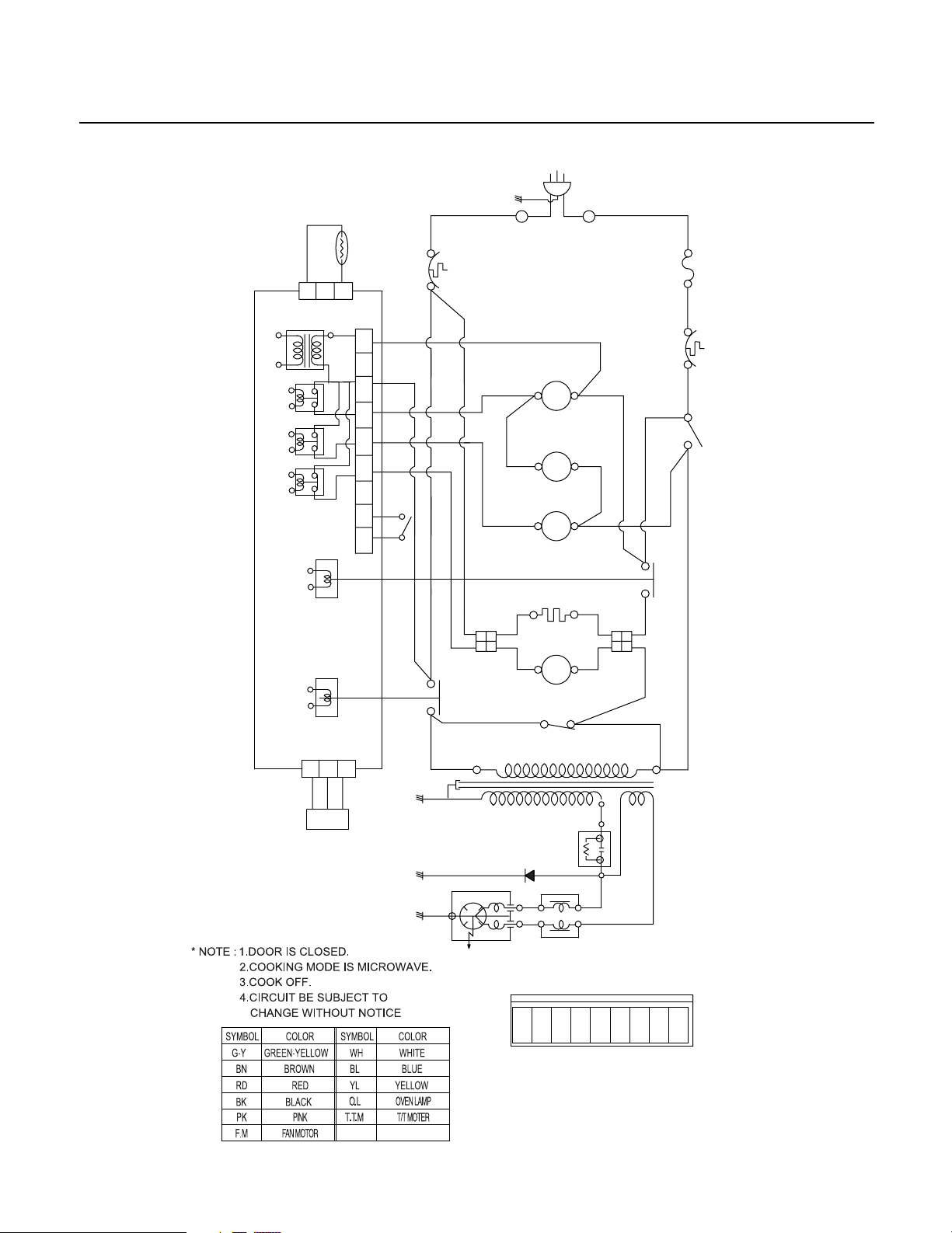
SCHEMATIC DIAGRAM (I) *Check the Model No.
H.V
FUSE
OVEN
THERMOSTAT
TRANSFORMER
O.L
T.T.M
TURN
AC 120V/60Hz
SINGLE PHASE ONLY
MOTOR
L.V.TRANSFORMER
F.M
OVEN
LAMP
FAN
MOTOR
TABLE
RELAY
RELAY
MONITOR
SWITCH
(NC)(C)
RD
BK
WH
BL
BL
BK
BN
WH
CONTROL MODULE
(9 PIN )
CONNECTOR
BK BL BN
CHOKE FILTER(Optional)
CAPACITOR
H.V.DIODE
MAGNETRON
H.V.
N
L
FAN
YL
RELAY
MOTOR
HEATER
POWER
RELAY
MAIN
WH
THERMISTOR
C.M
BK
PRIMARY
SWITCH
MGT
THERMOSTAT
BN
CIRC.
MOTOR
RELAY
BK
RD
BN
BK
CONVECTION
HEATER
CONVECTION
MOTOR
YLBL
BK
WH
YLWH PK PK
(RY5)
(RY2)
(RY1)
(RY4)
(RY6)
1
3
8
(CN1)
MAIN PCB
5
1
3
3
12
(CN2)
(CN4)
9
4
6
PK
PK
BNWHRD
SENSOR
1756
9
43
8
4-4
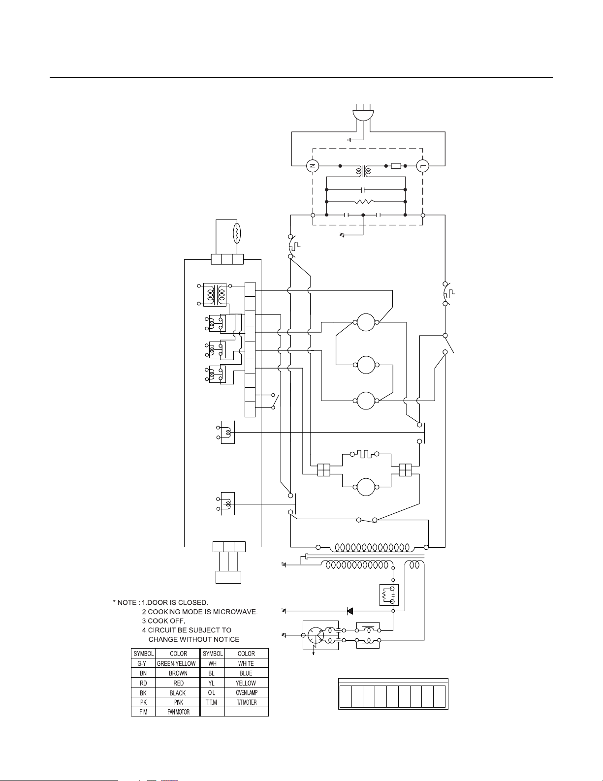
SCHEMATIC DIAGRAM (II) *Check the Model No. (ADD Noise filter)
H.V
OVEN
THERMOSTAT
TRANSFORMER
O.L
T.T.M
TURN
MOTOR
L.V.TRANSFORMER
F.M
OVEN
LAMP
FAN
MOTOR
TABLE
RELAY
RELAY
MONITOR
SWITCH
(NC)(C)
RD
BK
WH
BL
BL
BK
BN
WH
CONTROL MODULE
(9 PIN )
CONNECTOR
BK BL BN
CHOKE FILTER(Optional)
CAPACITOR
H.V.DIODE
MAGNETRON
H.V.
FAN
YL
RELAY
MOTOR
HEATER
POWER
RELAY
MAIN
WH
THERMISTOR
C.M
BK
PRIMARY
SWITCH
MGT
THERMOSTAT
BN
CIRC.
MOTOR
RELAY
BK
RD
BN
BK
CONVECTION
HEATER
CONVECTION
MOTOR
YLBL
BK
WH
YLWH PK PK
(RY5)
(RY2)
(RY1)
(RY4)
(RY6)
1
3
8
(CN1)
MAIN PCB
5
1
3
3
12
(CN2)
(CN4)
9
4
6
PK
PK
BNWHRD
SENSOR
1756
9
43
8
FUSE
WH
G-Y
WH
NOISE
FILTER
INPUT
POWER
BK
BK
4-5
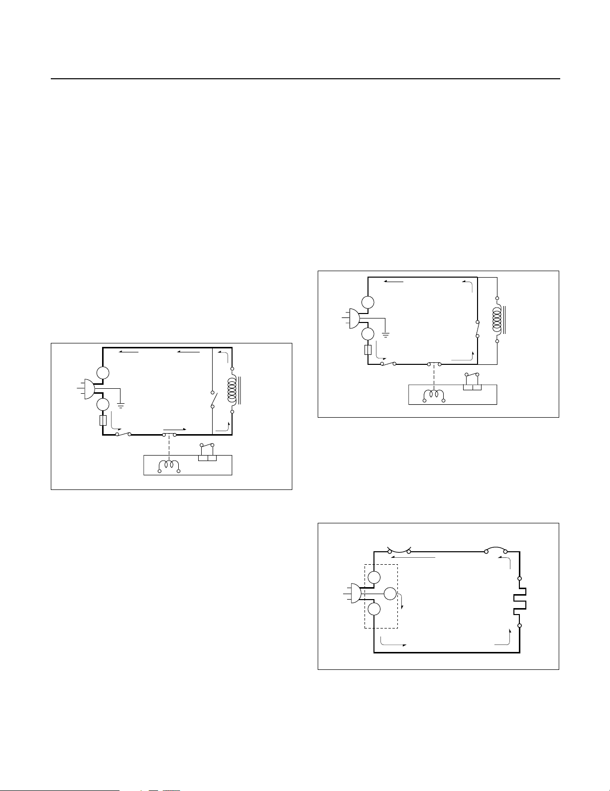
CIRCUIT DESCRIPTION
L
FUSE
H.V.
TRANS-
FORMER
RELAY 2
MICOM CONTROLLER
SECONDARY
SWITCH
PRIMARY
SWITCH
MONITOR
SWITCH
N
L
GENERAL DETAILS
• The low voltage transformer supplies the necessary
voltage to the micom controller when power cord is
plugged in.
• When the door is closed, the primary switch is ON, the
secondary switch is ON, and the monitor switch opens
(contact COM and NO).
WHEN SELECTING COOKING POWER
LEVEL AND TIME
• The micom controller memorizes the function you set.
• The time you set appears in the display window.
• Each indicator light turns on to indicate that the stage
has been set.
WHEN TOUCHING THE START PAD
• The coil of the relay is energized by the micom
controller.
• Power input is supplied to the high voltage transformer
through the fuse to the primary switch and relay 2.
• Turntable rotates.
WHEN THE DOOR IS OPENED DURING
COOKING
• Both the primary switch and relay 2 cut off the primary
winding voltage of the high voltage transformer.
• ON-OFF of relay 2 is coupled electrically with opening
and closing of the secondary switch.
• When the door is opened, the secondary switch is
opened and when the door is closed, the secondary
switch is closed.
• The cooking time stops counting down.
• Relay stops functioning.
• As the door is opened, if the contact of primary switch
and relay 2 and/or secondary switch fail to open, the
fuse opens due to the large current surge caused by the
monitor switch activation, which in turn stops magnetron
oscillation.
N
H.V.
TRANS-
FORMER
SECONDARY
SWITCH
FUSE
L
L
PRIMARY
SWITCH
RELAY 2
MONITOR
SWITCH
• The fan motor rotates and cools the magnetron by
blowing the air.
• The air is also directed into the oven to exhaust the
vapor in the oven through the upper plate.
• Cooking time starts counting down.
• 3.15 volts AC is generated from the filament winding of
the high voltage transformer. This 3.15 volts is applied
to the magnetron to heat the magnetron filament
through two noise-preventing choke coils.
• A high voltage of approximately 2,210 volts AC is
generated in the secondary of the high voltage
transformer which is increased by the action of the high
voltage diode and charging of the high voltage
capacitor.
• The negative 4,000 Volts DC is applied to the filament
of the magnetron.
WHEN THE OVEN IS SET AT ANY LEVEL
EXCEPT MAXIMUM.
• The micom controller controls the ON-OFF time of relay
2 by the applied signal to vary the average output power
of microwave oven as POWER LEVEL. (refer to page 1-1)
• One complete cycle of relay 2 is 22 seconds.
MICOM CONTROLLER
WHEN TOUCHING THE START KEY
WITH THE CONVECTION COOKING.
• The contacts of the primary switch and the secondary
switch close the circuit.
• Damper close.
• Turntable rotate.
• Fan Motor, Circulation Motor rotate.
4-6
OVEN THERMOSTAT
N
G-Y
E
L
L
RELAY 4
CONVECTION
HEATER
 Loading...