

LG LM6200, LM9600, EM9600, LM3400, LS5650 Owner's Manual
...
www.lg.com
OWNER’S MANUAL
EXTERNAL CONTROL
DEVICE SETUP
Please read this manual carefully before operating the
set and retain it for future reference.
EM9600 LM7600 G2 LM6200 LM3400 LS5600/5650
LM9600 LM6700 LS4600 LS5700/5750 CS570 LM4700
LM9500 LM6450 LS4000 LM5800/5850 CM565 LM4600
LM8600 LM6400 LM3700
Available series
IR CODES (USIng ExtERnal IR BlaStER)
(Depending on model)
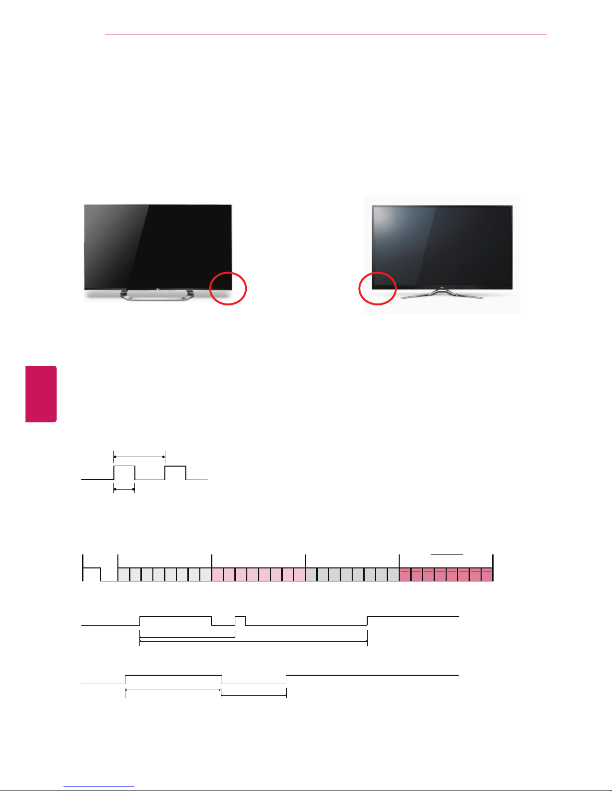
Position of Receiver on the TV
Remote Control IR Codes
Output waveform
Single pulse, modulated with 37.917kHz signal at 455kHz
T1
Tc
Frame configuration
1st frame
C0 C1 C2 C3 C4 C5 C6 C7 C0 C1 C2 C3 C4 C5 C6 C7 D0 D1 D2 D3 D4 D5 D6 D7 D0 D1 D2 D3 D4 D5 D6 D7
Lead code Low custom code High custom code Data code Data code
Repeat frame
Repeat code
Tf
Lead code
4.5 ms
9 ms
LCD PDP
2
Eng
EnglISH
IR CODES
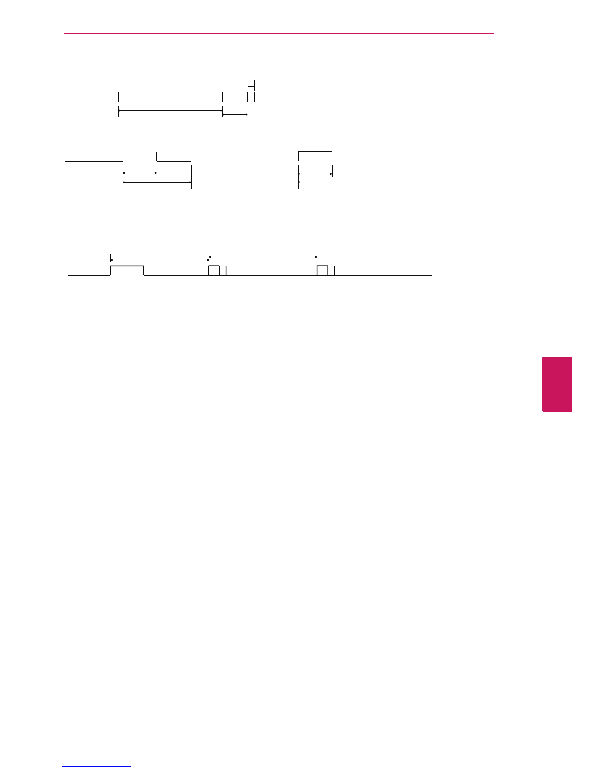
Repeat code
2.25 ms
9 ms
0.55 ms
Bit description
0.56 ms
1.12 ms
0.56 ms
2.24 ms
Bit “0” Bit “1”
Frame interval: Tf
The waveform is transmitted as long as a key is depressed.
Tf Tf
Tf=108ms @455KHz
3
Eng
EnglISH
IR CODES

Code
(Hexa)
Function Note
Code
(Hexa)
Function Note
08 POWER Remote control Button
(Power On/Off)
0F TV Remote control Button
DC 3D Remote control Button
45
Q.MENU
Remote control Button 5B EXIT Remote control Button
43 Home Remote control Button D6 TV Discrete IR Code
(TV Input Selection)
0B INPUT Remote control Button
10 - 19 Number Key 0-9 Remote control Button C4 POWER ON Discrete IR Code
(Only Power Off)
4C - (Dash)/LIST Remote control Button
1A FLASHBK Remote control Button C5 POWER OFF Discrete IR Code
(Only Power Off)
09 MUTE/DELETE Remote control Button
02 VOL + Remote control Button 5A AV1 Discrete IR Code
(AV1 Input Selection)
03 VOL - Remote control Button
00
CH
^
Remote control Button D0 AV2 Discrete IR Code
(AV2 Input Selection)
01
CH
v
Remote control Button
1E FAV/MARK Remote control Button BF COMPONENT1 Discrete IR Code
(Component1 Input
Selection)
40
^
Remote control Button
41
v
Remote control Button D4 COMPONENT2 Discrete IR Code
(Component2 Input
Selection)
07
<
Remote control Button
06
>
Remote control Button D5 RGB-PC Discrete IR Code
(RGB-PC Input Selection)
44 ENTER Remote control Button
28 BACK Remote control Button CE HDMI1 Discrete IR Code
(HDMI1 Input Selection)
79 RATIO Remote control Button
BA (
Plasma
)
FREEZE Remote control Button CC HDMI2 Discrete IR Code
(HDMI2 Input Selection)
95
ENERGY SAVING
Remote control Button
7E SIMPLINK Remote control Button E9 HDMI3 Discrete IR Code
(HDMI3 Input Selection)
AA INFO Remote control Button
30 AV MODE Remote control Button DA HDMI4 Discrete IR Code
(HDMI4 Input Selection)
72 RED Remote control Button
71 GREEN Remote control Button 76 Ratio 4:3 Discrete IR Code
(Only 4:3 Mode)
63 YELLOW Remote control Button
61 BLUE Remote control Button 77 Ratio 16:9 Discrete IR Code
(Only 16:9 Mode)
B1
n
Remote control Button
B0
Remote control Button AF Ratio Cinema
Zoom
Discrete IR Code
(Only Cinema Zoom Mode)
BA
yy
Remote control Button
8E
Remote control Button
8F
Remote control Button
Use the feature depending on your model.
4
Eng
EnglISH
IR CODES
ExtERnal COntROl DEVICE SEtUP
RS-232C Setup
Connect the RS-232C (serial port) input jack to
an external control device (such as a computer or
an A/V control system) to control the product’s
functions externally.
Connect the serial port of the control device to the
USB jack on the product back panel.
NOTE
RS-232C on this TV is intended to be used
with third party RS-232C control hardware
and software. The instructions below
are provided to help with programming
software or to test functionality using telenet
software. RS-232C connection cables are not
supplied with the product.
It is not able to control the multiple TVs
connected to the one external control
box(Such as A/V control system) individually.
Basically, this function works when TV is
power on.
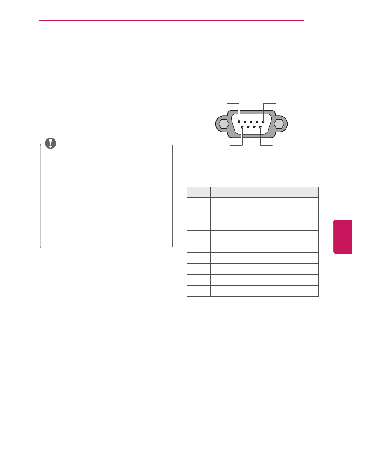
Type of connector;
RS232C to USB cable
1 5
6 9
RS-232C IN
(CONTROL & SERVICE)
No. Pin name
1 No connection
2 RXD (Receive data)
3 TXD (Transmit data)
4 DTR (DTE side ready)
5 GND
6 DSR (DCE side ready)
7 RTS (Ready to send)
8 CTS (Clear to send)
9 No Connection
5
Eng
EnglISH
EXTERNAL CONTROL DEVICE SETUP

Recommanded cable
- Model name: UC232-A
- Manufacturer : DataPro
(URL: http://www.datapro.net/products/usb-tors232-serial-convertor.html)
6
Eng
EnglISH
EXTERNAL CONTROL DEVICE SETUP
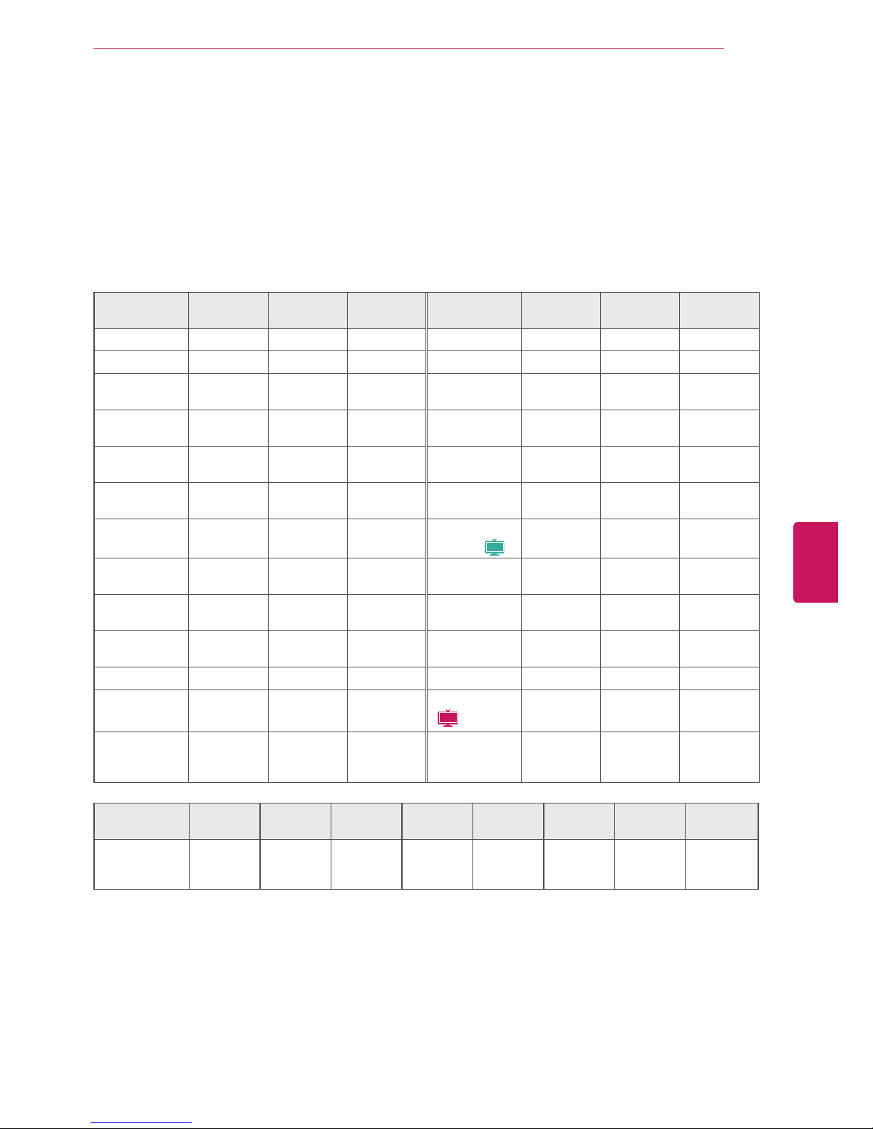
Command reference list
Communication Parameters
Baud rate: 9600 bps (UART)
Data length: 8 bits
Parity : None
Stop bit: 1 bit
Communication code: ASCII code
Use a crossed (reverse) cable.
COMMAND1 COMMAND2
DATA
(Hexadecimal)
COMMAND1 COMMAND2
DATA
(Hexadecimal)
01. Power Off k a 00 14. Treble k r 00 - 64
02. Input Select x b (See p.9) 15. Bass k s 00 - 64
03. Aspect
Ratio
k c (See p.9) 16. Balance k t 00 - 64
04. Screen
Mute
k d 00 - 01
17. 3D (For 3D
TV)
x t (See p.10)
05. Volume
Mute
k e 00 - 01
18. Color
Temperature
x u 00 - 64
06. Volume
Control
k f 00 - 64
19.Extended
3D (For 3D TV)
x v (See p.10)
07. Contrast k g 00 - 64
20. ISM
Method (
Plasma
)
j p (See p.11)
08. Brightness k h 00 - 64
21. Energy
Saving
j q (See p.11)
09. Color k i 00 - 64
22. Auto
Configuration
j u (See p.11)
10. Tint k j 00 - 64
24. Channel
Add/Del
m b 00 - 01
11. Sharpness k k 00 - 64 25. Key m c (See p.11)
12. OSD Select k l 00 - 01
26. Backlight
(
LCD
)
m g 00 - 64
13. Remote
Control Lock
Mode
k m 00 - 01
COMMAND1 COMMAND2
DATA00
(Hexadecimal)
DATA01
(Hexadecimal)
DATA02
(Hexadecimal)
DATA03
(Hexadecimal)
DATA04
(Hexadecimal)
DATA05
(Hexadecimal)
23. Channel
Tuning
m a
physical
program
high
major
program
low
major low minor high minor low attribute
7
Eng
EnglISH
EXTERNAL CONTROL DEVICE SETUP

Transmission / Receiving protocol
Transmission
[Command1][Command2][ ][0][ ][Data][Cr]
[Command 1] : First command to control the set.(j, k, m or x)
[Command 2] : Second command to control the set.
[DATA] : To transmit the command data.
Transmit the ‘FF’ data to read status of command.
[Cr] : Carriage Return
ASCII code ‘0x0D’
[ ] : ASCII code ‘space (0x20)’
* In this model, set will not send the status during the standby mode.
OK Acknowledgement
[Command2][ ][0][ ][OK][Data][x]
The set transmits ACK (acknowledgement) based on this format when receiving normal data. At this time,
if the data is data read mode, it indicates present status data. If the data is data write mode, it returns the
data of the PC computer.
* In this model, set will not send the status during the standby mode.
* Data Format
[Command 2] : Use as command.
[DATA] : Use the small character, if data is 0 x ab, it will send the ‘a’, ‘b’.
[OK] : Use the large character.
Error Acknowledgement
[Command2][ ][0][ ][NG][Data][x]
The set transmits ACK (acknowledgement) based on this format when receiving abnormal data from nonviable functions or communication errors.
Data1: Illegal Code
Data2: Not supported function
Data3: Wait more time
* In this model, set will not send the status during the standby mode.
* Data Format
[Command 2] : Use as command.
[DATA] : Use the small character, if data is 0 x ab, it will send the ‘a’, ‘b’.
[NG] : Use the large character
8
Eng
EnglISH
EXTERNAL CONTROL DEVICE SETUP

01. Power off (Command: k a)
To control Power Off of the set.
Transmission [k][a][ ][0][ ][Data][Cr]
Data 00: Power Off
Acknowledgement [a][ ][0][ ][OK/NG][Data][x]
* In a like manner, if other functions transmit ‘FF’
data based on this format, Acknowledgement data
feedback presents status about each function.
* Note: In this model, set will send the Acknowledge
after power on processing completion.
There might be a time delay between command and
acknowledge.
02. Input Select (Command: x b)
To select input source for set.
Transmission [x][b][ ][0][ ][Data][Cr]
Data 00: DTV (Antenna) Data 01: DTV (Cable)
Data 10: Analog (Antenna) Data 11: Analog (Cable)
Data 20: AV or AV1 Data 21: AV2
Data 40: Component1 Data 41: Component2
Data 42: Component3 Data 60: RGB-PC
Data 90: HDMI1 Data 91: HDMI2
Data 92: HDMI3 Data 93: HDMI4
Acknowledgement [b][ ][0][ ][OK/NG][Data][x]
* Use the feature depending on your model.
03. Aspect Ratio (Command: k c)
To adjust the screen format.
Transmission [k][c][ ][0][ ][Data][Cr]
Data 01: 4:3 Data 09: Just scan
Data 02: 16:9 Data 10: Cinema Zoom 1
Data 06: Set by program
…
Data 1F: Cinema Zoom16
Acknowledgement [c][ ][0][ ][OK/NG][Data][x]
04. Screen Mute (Command: k d)
To select screen mute on/off.
Transmission [k][d][ ][0][ ][Data][Cr]
Data 00:
Screen mute off (Picture on), Video-out
Mute off
Data 01: Screen mute on (Picture off)
Data 10: Video-out Mute on
Acknowledgement [d][ ][0][ ][OK/NG][Data][x]
* In case of Video-out Mute on only,
TV will display On
Screen Display (OSD). But, in case of screen mute on,
TV will not display On Screen Display (OSD).
05. Volume Mute (Command: k e)
To control volume mute on/off.
You can also adjust mute using the MUTE button on
remote control.
Transmission [k][e][ ][0][ ][Data][Cr]
Data 00: Volume mute on (Volume off)
Data 01: Volume mute off (Volume on)
Acknowledgement [e][ ][0][ ][OK/NG][Data][x]
06. Volume Control (Command: k f)
To adjust volume.
You can also adjust volume with the volume buttons
on remote control.
Transmission [k][f][ ][0][ ][Data][Cr]
Data Min: 00 ~ Max: 64 (*transmit by Hexadecimal
code)
*Refer to “Real data mapping”.
Acknowledgement [f][ ][0][ ][OK/NG][Data][x]
07. Contrast (Command: k g)
To adjust screen contrast.
You can also adjust contrast in the PICTURE menu.
Transmission [k][g][ ][0][ ][Data][Cr]
Data Min: 00 ~ Max: 64 (*transmit by Hexadecimal
code)
*Refer to “Real data mapping”.
Acknowledgement [g][ ][0][ ][OK/NG][Data][x]
08. Brightness (Command: k h)
To adjust screen brightness.
You can als o adjust brightness in the PICTURE
menu.
Transmission [k][h][ ][0][ ][Data][Cr]
Data Min: 00 ~ Max: 64 (*transmit by Hexadecimal
code)
*Refer to “Real data mapping”.
Acknowledgement [h][ ][0][ ][OK/NG][Data][x]
09. Color (Command: k i)
To adjust screen color.
You can also adjust color in the PICTURE menu.
Transmission [k][i][ ][0][ ][Data][Cr]
Data Min: 00 ~ Max: 64 (*transmit by Hexadecimal
code)
*Refer to “Real data mapping”.
Acknowledgement [i][ ][0][ ][OK/NG][Data][x]
10. Tint (Command: k j)
To adjust screen tint.
You can also adjust tint in the PICTURE menu.
Transmission [k][j][ ][0][ ][Data][Cr]
Data Red: 00 ~ Green: 64 (*transmit by Hexadecimal
code)
*Refer to “Real data mapping”.
Acknowledgement [ j ][ ][0][ ][OK/NG][Data][x]
11. Sharpness (Command: k k)
To adjust screen sharpness.
You can also adjust sharpness in the PICTURE menu.
Transmission [k][k][ ][0][ ][Data][Cr]
Data Min: 00 ~ Max: 64 (*transmit by Hexadecimal
code)
*Refer to “Real data mapping”.
Acknowledgement [k][ ][0][ ][OK/NG][Data][x]
9
Eng
EnglISH
EXTERNAL CONTROL DEVICE SETUP

12. OSD Select (Command: k l)
To select OSD (On Screen Display) on/off.
Transmission [k][l][ ][0][ ][Data][Cr]
Data 00: OSD off Data 01: OSD on
Acknowledgement [l][ ][0][ ][OK/NG][Data][x]
13. Remote Control Lock Mode (Command: k m)
To lock the remote contr ol and the front panel
controls on the set.
Transmission [k][m][ ][0][ ][Data][Cr]
Data 00: Lock off Data 01: Lock on
Acknowledgement [m][ ][0][ ][OK/NG][Data][x]
If you’re not using the remote control and front panel
controls on the Monitor set, use this mode. When
main power is on/off, remote control lock is released.
If Key Lock is on in the standby mode, TV will not
turn on by POWER button of remote control and on
the TV.
14. Treble (Command: k r)
To adjust treble.
You can also adjust treble in the AUDIO menu.
Transmission [k][r][ ][0][ ][Data][Cr]
Data Min: 00 ~ Max: 64 (*transmit by Hexadecimal
code)
*Refer to “Real data mapping”.
Acknowledgement [r][ ][0][ ][OK/NG][Data][x]
15. Bass (Command: k s)
To adjust bass.
You can also adjust bass in the AUDIO menu.
Transmission [k][s][ ][0][ ][Data][Cr]
Data Min: 00 ~ Max: 64 (*transmit by Hexadecimal
code)
*Refer to “Real data mapping”.
Acknowledgement [s][ ][0][ ][OK/NG][Data][x]
16. Balance (Command: k t)
To adjust balance.
You can also adjust balance in the AUDIO menu.
Transmission [k][t][ ][0][ ][Data][Cr]
Data Min: 00 ~ Max: 64 (*transmit by Hexadecimal
code)
*Refer to “Real data mapping”.
Acknowledgement [t][ ][0][ ][OK/NG][Data][x]
17. 3D (Command: x t) (For 3D TV)
To change 3D mode for TV.
Transmission [x][t][ ][0][ ][Data01]
[ ][Data02][ ][Data03][ ][Data04][Cr]
Data1
00: 3D On 01: 3D Off
02: 3D to 2D 03: 2D to 3D
Data2
00: Top and Bottom 01: Side by Side
02: Check Board 03: Frame Sequential
Data3
00: Right to Left 01: Left to Right
Data4
3D Depth: Min : 00 ~ Max : 14
(*transmit by Hexadecimal code)
* If data1 is 00 (3D On), data4 has no meaning.
* If data1 is 01 (3D off) or 02 (3D to 2D), data2, data3
and data4 have no meaning.
* If data1 is 03 (2D to 3D), data2 and data3 have no
meaning.
Data 1 Data 2 Data 3 Data 4
00 o o x
01 x x x
02 x x x
03 x x o
x : Don’t care
Acknowledgement [t][ ][OK][Data01][Data02]
[Data03][Data04][x][t][ ][NG][Data01][x]
18. Color Temperature (Command: x u)
To adjust color temperature.
You ca n also adjust co l o r temperature in th e
PICTURE menu.
Transmission [x][u][ ][0][ ][Data][Cr]
Data Min: 00 ~ Max: 64 (*transmit by Hexadecimal
code)
*Refer to “Real data mapping”.
Acknowledgement [u][ ][0][ ][OK/NG][Data][x]
19. Extended 3D (Command: x v) (For 3D TV)
To change 3D option for TV.
Transmission [x][v][ ][0][ ][Data01][ ][Data02][Cr]
Data1: 3D option
00: 3D Picture Correction
01: 3D Depth (2D to 3D Only)
02: 3D Viewpoint
03: 3D Picture Size
04: 3D Picture Balance
05: 3D Optimization
Data2: It has own range for each 3D option
determined by Data1.
1) When Data1 is 00
00: Right to Left 01: Left to Right
2) When Data1 is 01
Data Min: 00 ~ Max: 14 (*transmit by Hexadecimal code)
3) When Data1 is 02
Data Min: 00 ~ Max: 14 (*transmit by Hexadecimal code)
4) When Data1 is 03
00: Just Scan 01: 16:9
5) When Data1 is 04
00: Off 01: On
6) When Data1 is 05
Data Min: 00 ~ Max: 02 (*transmit by Hexadecimal code)
Acknowledgement [v][ ][OK][Data01][Data02][x]
[v][ ][NG][Data01][x]
* Use the feature depending on your model.
10
Eng
EnglISH
EXTERNAL CONTROL DEVICE SETUP

20. ISM Method (Command: j p) (
Plasma
)
To avoid having a fixed image remain on screen.
Transmission [j][p][ ][0][ ][Data][Cr]
Data 02: Orbiter
04: White Wash
08: Normal
20: Color Wash
Acknowledgement [p][ ][0][ ][OK/NG][Data][x]
21. Energy Saving (Command: j q)
To control the energy saving function.
Transmission [ j ][q][ ][0][ ][Data][Cr]
Data 00: off
01: Minimum
02: Medium
03: Maximum
04: Auto (Depending on model)
05: Screen off
Acknowledgement [q][ ][0][ ][OK/NG][Data][x]
22. Auto Configuration (Command: j u)
To ad just picture positio n and minimi ze image
shaking automatically. Auto configuration only works
in RGB-PC mode.
Transmission [ j ][u][ ][0][ ][Data][Cr]
Data 01: To set
Acknowledgement [u][ ][0][ ][OK/NG][Data][x]
23. Channel Tuning (Command: m a)
To tune channel to following physical/major/minor
number.
(This feature is not available for all models.)
Transmission [m][a][ ][0][ ][Data00][ ][Data01]
[ ][Data02][ ][Data03][ ][Data04][ ][Data05][Cr]
Digital channels have a Physical, Major, and Minor
channel number. The Physical number is the actual
digital channel number, the Major is the number that
the channel should be mapped to, and the Minor is
the sub-channel. Since the ATSC tuner automatically
maps the channel to the Major number, the Physical
number is not required when sending a command.
Data 00: Physical Channel Number
NTSC air: 02~45, NTSC cable: 01, 0E~7D
ATSC air: 01~45, ATSC cable: 01~87
Data 01 & 02: Major Channel Number
Data 01: High byte Data 02: Low byte
Two bytes are available for the Major and Minor,
normally only the second byte is used.
Data 03 & 04: Minor Channel Number
Not needed for NTSC.
The table lists the bi nary code which must be
converted to He xade cima l before se ndin g. For
example:
The binary code to tune the sub source to an NTSC
cable channel is “1000 0001”, which translates to
“81” in Hex.
* 7th bit : For which source do you want to change
the channel.
* 6th bit: Use a two part or one part channel. Most
cases just use 0 since it’s ignored when using
NTSC.
* 5th bit: Use 0 with NTSC since it can only use
the physical channel number. Normally use 1 for
ATSC since most times it doesn’t matter what the
physical number is.
* 4th bit: Set to 0.
* 3-0 bits: Choose signal type.
* Tune Command Examples:
1. Tune to the analog (NTSC) cable channel 35.
Data 00 = Physical of 35 = 23
Data 01 & 02 = No Major = 00 00
Data 03 & 04 = No Minor = 00 00
Data 05 = 0000 0001 in binary = 01
Total = ma 00 23 00 00 00 00 01
2. Tune to the digital (ATSC) local channel 30-3.
Data 00 = Don’t know Physical = 00
Data 01 & 02 = Major is 30 = 00 1E
Data 03 & 04 = Minor is 3 = 00 03
Data 05 = 0010 0010 in binary = 22
Total = ma 00 00 00 1E 00 03 22
24. Channel Add/Del (Command: m b)
To add and delete the channels.
Transmission [m][b][ ][0][ ][Data][Cr]
Data 00: Channel Delete Data 01: Channel Add
Acknowledgement [b][ ][0][ ][OK/NG][Data][x]
25. Key (Command: m c)
To send IR remote key code.
Transmission [m][c][ ][0][ ][Data][Cr]
See page 131.
Acknowledgement [c][ ][0][ ][OK/NG][Data][x]
When TV is in the standby mode, TV will turn on by
POWER button of remote control only.
26. Backlight (Command: m g) (
LCD
)
To adjust screen backlight.
Transmission [m][g][ ][0][ ][Data][Cr]
Data Min:00 ~ Max:64 (*transmit by Hexadecimal
code)
*Refer to “Real data mapping”.
Acknowledgement [g][ ][0][ ][OK/NG][Data][x]
11
Eng
EnglISH
EXTERNAL CONTROL DEVICE SETUP
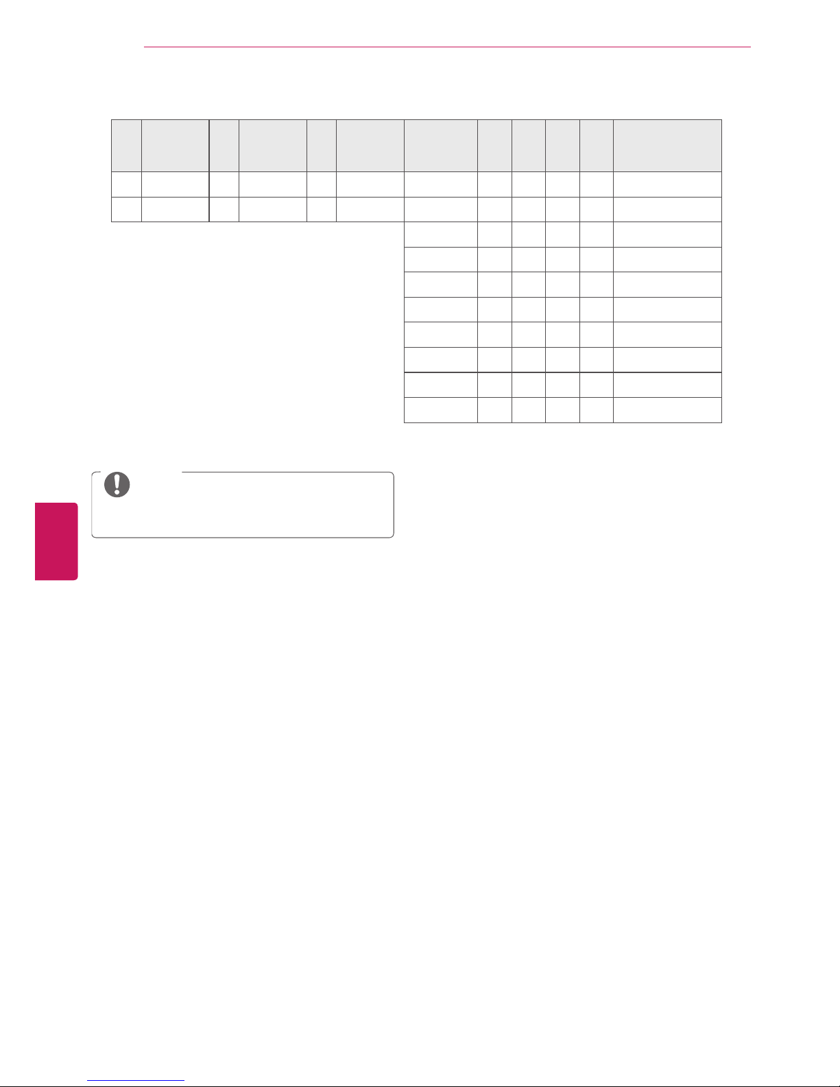
* Table List (Channel Tuning)
7
Main/Sub
Picture
6
Two/One
Part
Channel
5
Using
Physical
Channel
4
Reserved
3 2 1 0 Step
0 Main 0 Two 0 Use x 0 0 0 0 NTSC Air
1 Sub 1 One 1 No Use x 0 0 0 1 NTSC Cable
x 0 0 1 0 ATSC Air
x 0 0 1 1 ATSC Cable_std
x 0 1 0 0 ATSC Cable_hrc
x 0 1 0 1 ATSC Cable_irc
x 0 1 1 0 ATSC cable_auto
x 0 1 1 1 Reserved
x x x x x ...
x 1 1 1 1 Reserved
NOTE
Some features can not be available depeding
on models.
12
Eng
EnglISH
EXTERNAL CONTROL DEVICE SETUP

 Loading...