

Page 1

COLOR MONIT OR
SER VICE MANUAL
CAUTION
BEFORE SERVICING THE UNIT,
READ THE SAFETY PRECAUTIONS IN THIS MANUAL.
CHASSIS NO. : CL-38
F ACTORY MODEL: LM505J
MODEL: L1510M (LM505J-GL)
*( ) ID LABEL MODEL No.
Page 2
CONTENTS
SPECIFICATIONS
- 2 -
1. LCD CHARACTERISTICS
Type : TFT XGA LCD Module
Size : 352.0(H) x 263.5(V) x 14.0(T)
Pixel Pitch : 0.297mm x 0.297mm
Color Depth : 8Bits/ 16M colors
Active Video Area : 15.0 inch
(304.128 x 228.096)
Surface Treatment : Anti-Glare
Backlight Unit : Top/Bottom edge side 2CCFL
Electrical Interface : LVDS/TTL interface
2. OPTICAL CHARACTERISTICS
2-1. Viewing Angle by Contrast Ratio
≥
10
Left : 60° min.
Right : 60° min.
Top : 45° min.
Bottom : 45° min.
2-2. Luminance : 200(min.), 250(typ.) at Center point
2-3. Contrast Ratio :250(min.), 350(typ.)
3. SIGNAL (Refer to the Timing Chart)
3-1. Sync Signal
1) Type : Separate Sync. (Horizontal & Vertical)
2) Input Voltage Level: Low=0~0.8V, High=2.1~5.5V
3) Sync Polarity : Positive or Negative
3-2. Video Input Signal
1) Type : R, G, B Analog
2) Voltage Level : 0~0.714 V
a) Color 0, 0 : 0 Vp-p
b) Color 7, 0 : 0.467 Vp-p
c) Color 15, 0 : 0.714 Vp-p
3) Input Impedance : 75 Ω
3-3. Operating Frequency
Horizontal : 31 ~ 63kHz(Automatic)
Vertical : 56 ~ 75Hz(Automatic)
4. POWER SUPPLY
4-1. Power
100~240V, 50/60Hz 0.6A
4-2. Power Consumption
5. ENVIRONMENT
5-1. Operating Temperature: 10°C~35°C (50°F~95°F)
(Ambient)
5-2. Relative Humidity : 10%~80%
(Non-condensing)
5-3. MTBF : 50,000 Hours (min.)
Lamp Life : 30,000 Hours (min.)
6. DIMENSIONS (with TILT/SWIVEL)
Width : 360.0mm (14.17'')
Depth : 153.0mm (6.02'')
Height : 359.8mm (14.16'')
7. WEIGHT (with TILT/SWIVEL)
Net. Weight : 4.15kg (9.15 lbs)
Gross Weight : 5.5kg (12.13 lbs)
8. Audio
RMS Audio Output : 1W + 1W(R+L)
Input Sensitivity : 0.7Vrms
Speaker Impedance : 4
Ω
SPECIFICATIONS ................................................... 2
PRECAUTIONS ....................................................... 3
TIMING CHART ....................................................... 4
OPERATING INSTRUCTIONS ................................ 5
WIRING DIAGRAM ................................................. 7
BLOCK DIAGRAM ................................................... 8
DESCRIPTION OF BLOCK DIAGRAM.................... 9
ADJUSTMENT ...................................................... 10
TROUBLESHOOTING GUIDE .............................. 11
PRINTED CIRCUIT BOARD................................... 15
EXPLODED VIEW...................................................17
REPLACEMENT PARTS LIST ...............................19
PIN CONFIGURATION............................................23
SCHEMATIC DIAGRAM ........................................ 28
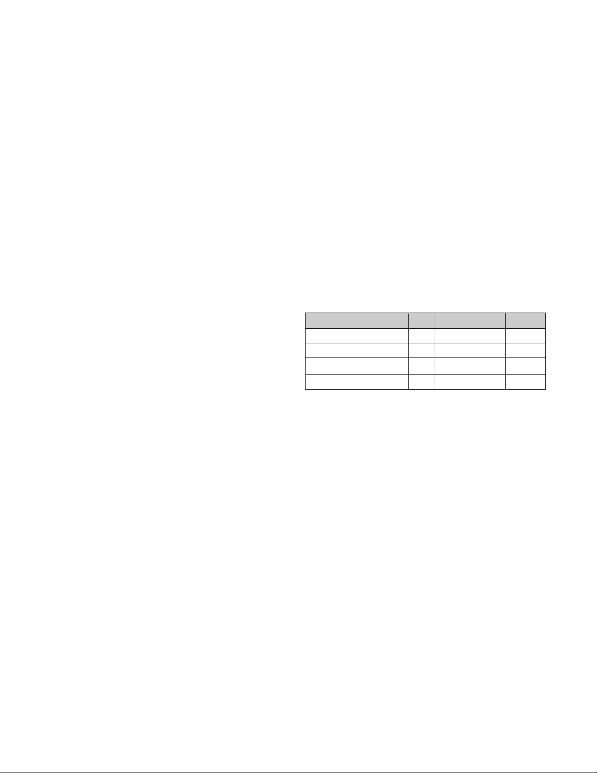
MODE
POWER ON (NORMAL)
STAND-BY
SUSPEND
DPMS OFF
H/V SYNC
ON/ON
OFF/ON
ON/OFF
OFF/OFF
POWER CONSUMPTION
less than 30 W
less than 3 W
less than 3 W
less than 3 W
LED COLOR
GREEN
AMBER
AMBER
AMBER
VIDEO
ACTIVE
OFF
OFF
OFF
Page 3

- 3 -
WARNING FOR THE SAFETY-RELATED COMPONENT.
• There are some special components used in LCD
monitor that are important for safety. These parts are
marked on the schematic diagram and the
replacement parts list. It is essential that these critical
parts should be replaced with the manufacturer’s
specified parts to prevent electric shock, fire or other
hazard.
• Do not modify original design without obtaining written
permission from manufacturer or you will void the
original parts and labor guarantee.
TAKE CARE DURING HANDLING THE LCD MODULE
WITH BACKLIGHT UNIT.
• Must mount the module using mounting holes arranged
in four corners.
• Do not press on the panel, edge of the frame strongly
or electric shock as this will result in damage to the
screen.
• Do not scratch or press on the panel with any sharp
objects, such as pencil or pen as this may result in
damage to the panel.
• Protect the module from the ESD as it may damage the
electronic circuit (C-MOS).
• Make certain that treatment person’s body are
grounded through wrist band.
• Do not leave the module in high temperature and in
areas of high humidity for a long time.
• The module not be exposed to the direct sunlight.
• Avoid contact with water as it may a short circuit within
the module.
• If the surface of panel become dirty, please wipe it off
with a softmaterial. (Cleaning with a dirty or rough cloth
may damage the panel.)
WARNING
BE CAREFUL ELECTRIC SHOCK !
• If you want to replace with the new backlight (CCFL) or
inverter circuit, must disconnect the AC adapter
because high voltage appears at inverter circuit about
650Vrms.
• Handle with care wires or connectors of the inverter
circuit. If the wires are pressed cause short and may
burn or take fire.
PRECAUTION
CAUTION
Please use only a plastic screwdriver to protect yourself
from shock hazard during service operation.
Page 4
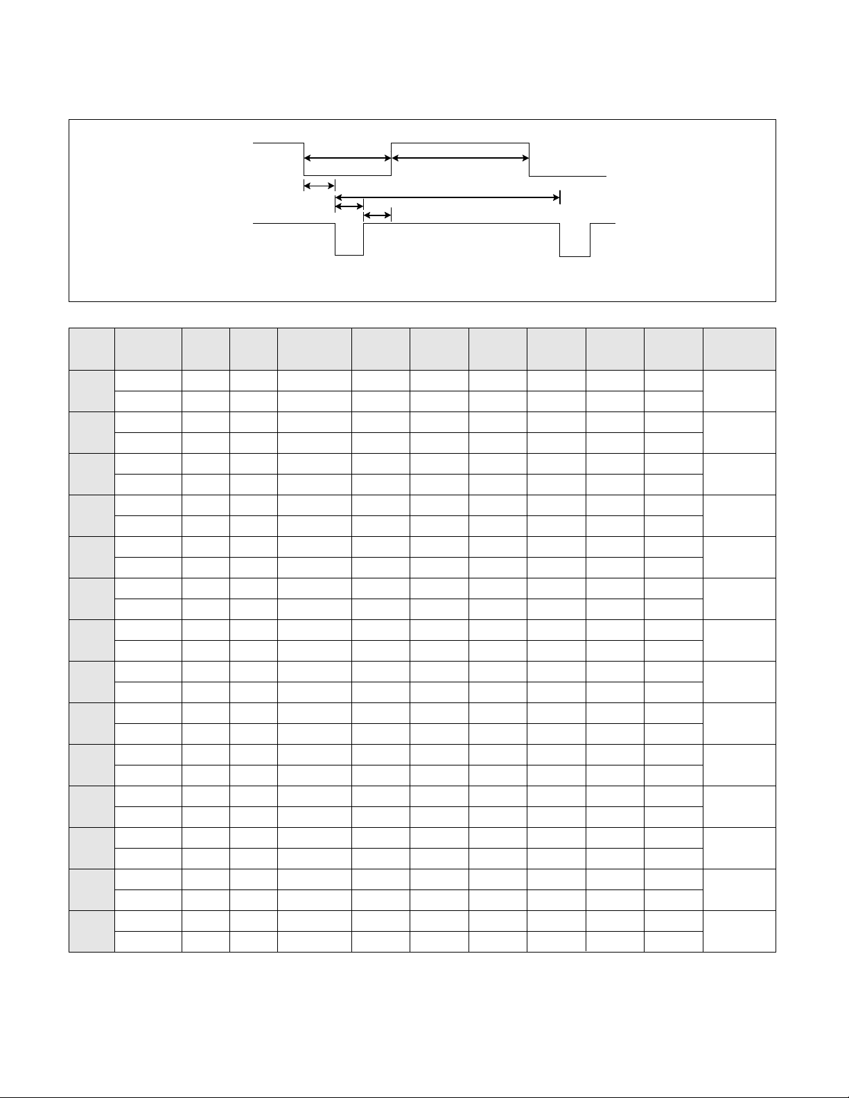
TIMING CHART
- 4 -
VIDEO
SYNC
B
D
C
F
E
A
H / V
H (Pixels)
V (Lines)
H (Pixels)
V (Lines)
H (Pixels)
V (Lines)
H (Pixels)
V (Lines)
H (Pixels)
V (Lines)
H (Pixels)
V (Lines)
H (Pixels)
V (Lines)
H (Pixels)
V (Lines)
H (Pixels)
V (Lines)
H (Pixels)
V (Lines)
H (Pixels)
V (Lines)
H (Pixels)
V (Lines)
H (Pixels)
V (Lines)
H (Pixels)
V (Lines)
Sync
Polarity
+
–
–
+
–
–
–
–
–
–
–
–
+
+
+
+
+
+
+
+
–
–
–
–
–
–
+
+
Dot
Clock
25.175
28.322
25.175
30.24
31.5
31.5
36.0
40.0
50.0
49.5
57.2832
65
75
78.75
Frequency
31.468 KHz
70.0 Hz
31.468 KHz
70.0 Hz
31.469 KHz
60.0 Hz
35.0 KHz
66.67 Hz
37.861 KHz
72.8 Hz
37.50 KHz
75 Hz
35.156KHz
56.25 Hz
37.879 KHz
60.3 Hz
48.077 KHz
72.188 Hz
46.875 KHz
75.0 Hz
49.725 KHz
74.55 Hz
48.363 KHz
60.0 Hz
56.476 KHz
70.0 Hz
60.023 KHz
75.0 Hz
Resolution
640 x 350
720 x 400
640 x 480
640 x 480
640 x 480
640 x 480
800 x 600
800 x 600
800 x 600
800 x 600
832 x 624
1024 x 768
1024 x 768
1024 x 768
Total
Period
( E )
800
449
900
449
800
525
864
525
832
520
840
500
1024
625
1056
628
1040
666
1056
625
1152
667
1344
806
1328
806
1312
800
Video
Active
Time ( A )
640
350
720
400
640
480
640
480
640
480
640
480
800
600
800
600
800
600
800
600
832
624
1024
768
1024
768
1024
768
Blanking
Time
( B )
160
99
180
49
160
45
224
45
192
40
200
20
224
25
256
28
240
66
256
25
320
43
320
38
304
38
288
32
Sync
Duration
( D )
96
2
108
2
96
2
64
3
40
3
64
3
72
2
128
4
120
6
80
3
64
3
136
6
136
6
96
3
Back
Porch
( F )
48
60
55
34
48
33
96
39
128
28
120
16
128
22
88
23
64
23
160
21
224
39
160
29
144
29
176
28
Front
Porch
( C )
16
37
17
13
16
10
64
3
24
9
16
1
24
1
40
1
56
37
16
1
32
1
24
3
24
3
16
1
MODE
1
2
3
4
5
6
7
8
9
10
11
12
13
14
(MAC)
(TEXT)
Page 5
- 5 -
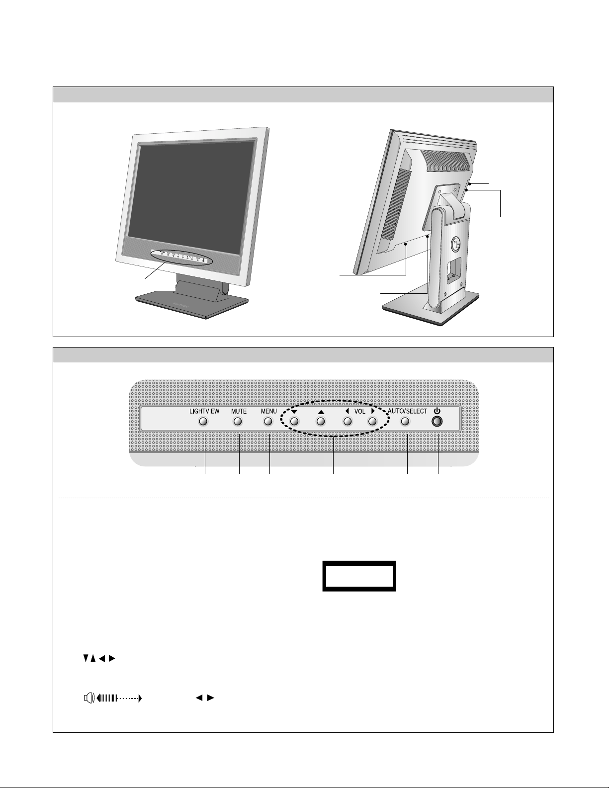
FRONT VIEW
REAR VIEW
Front Control Panel
1. Power Button
Use this button to turn the display on or off.
<Power (DPMS) Indicator>
This Indicator lights up green when the display
operates normally. If the display is in DPM (Energy
Saving) mode, this indicator color changes to
amber.
2. Menu Button
Use this button to enter or exit the On Screen
Display.
3. Button
Use these buttons to choose or adjust items in the
On Screen Display.
Volume:
Use these buttons to decrease or increase the
volume level
.
4. AUTO/
SELECT Button
Use this button to enter a selection in the On
Screen Display.
Power Connector
See front control panel
D-Sub Signal Connector
5 6 2 3 4 1
37
When adjusting your display
settings, always press the
AUTO/SELECT button before
entering the On Screen
Display(OSD). This will automatically adjust your display
image to the ideal settings for the current screen
resolution size (display mode). The best display mode is
1024x768.
PROCESSING
AUTO CONFIGURATION
OPERATING INSTRUCTIONS
HEAD PHONE
AUDIO IN
Page 6
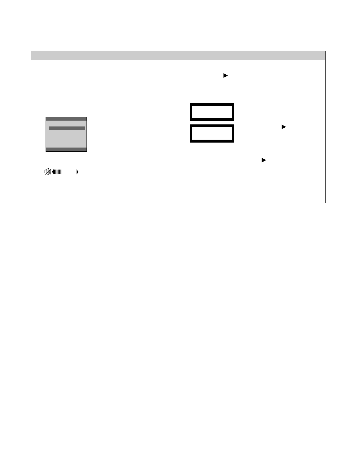
5. LIGHT VIEW
This function optimizes the brightness, contrast or
color value to the surrounding conditions and
settings and enables you to enjoy the most suitable
picture by adjusting the surroundings (DAY/NIGHT
/USER MODE)
6. MUTE
Used to select mute on (means sound off) and mute
off (means sound on).
※ CONTROLS LOCKED/UNLOCKED
:
MENU and Button for 3 seconds
Use this button to enter or exit the On Screen
Display.
OPERATING INSTRUCTIONS
- 6 -
Front Control Panel
• TEXT: For viewing letters
• MOVIE: For viewing movies
• PHOTO: For viewing pictures or
the photographs
• USER MODE: This function
memorizes the manual
adjustment -Brightness, Contrast
and Color value on the On
Screen Display.
LIGHT VIEW
DAY
NIGHT
USER MODE
TEXT
MOVIE
PHOTO
TEXT
MOVIE
PHOTO
37
This function allows you to secure
the current control settings, so
that they cannot be inadvertently
changed. Press and hold the
MENU button and button for 3
seconds: the message
“CONTROLS LOCKED”
appears.
You can unlock the OSD controls at any time by
pushing the MENU button and button for 3
seconds:
the message “CONTROLS UNLOCKED” will appear.
CONTROLS LOCKED
CONTROLS UNLOCKED
Page 7
- 8 -
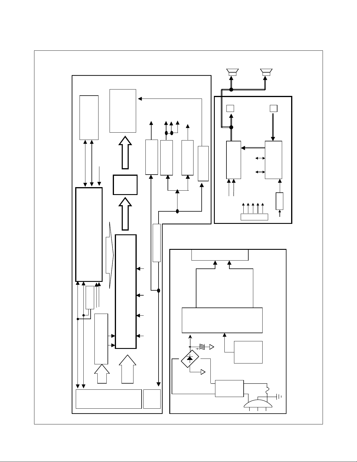
BLOCK DIAGRAM
EEPROM
24 LC08
ADC/PLL/Scaler
(GMZAN-2)
MICOM
(MTV312)
Sc hmit t Trigger
( 7 4HCT 14 A)
Panel
Interface
20 Pin
Connector
RGB
H.V
D-
Sub
15P
Control
S
C
LK
SDATA
CON
8P
Inverter
5VR
PL
MODPWR-
3.3V_PL3.3VD
5VR
3.3
3.3
3.3
3.3
3.3V
2.5
V_AD
Regulat or
Regulator
Regulat or
Regulat or
KA7805
BA033
BA033
VVV
D
ST
Hsync2
Vsync2
Hsyncm
Vsyncm
2.5VD
RC1171
VD
5VS
12V
CON 5P
<MAINBLOC
K>
_
_
AD
DSCL
DSDA
LVDS
Filter
BD
SMPS
Control
IC
TOP246
12V
5VS
CON 5P
<POWER BLOCK>
Headphone
Audio In
Audio
Processor
(TDA7449)
Audio Amp
(TDA7496L)
SCLSDA
78M08
8VA
12VA
CON 5P
12V
GND
SCL
SDA
Audio
Mute
Audio Mute
<AUDIO BLOCK>
U501
12V
U201
U502
U402
U701
U803
U802
U806
U805
U901
U902
EEPROM
24LC02
U702
Page 8

DESCRIPTION OF BLOCK DIAGRAM
- 9 -
1. Scaler One chip IC(GMZAN-2, U201)
GMZAN-2 (U201) is one chip IC which it supports four internal function blocks of Video Amp, PLL,
A/D converter and Video processor.
Video signal (0.7Vp.p) clamped through C209, 208, 207 with matching IC’s proper cut off voltage.
This signal is processed as a proper 8 bit digital signal by U201’s amplifying, phase locking, A/D converting,
and scaling operations.
U201 generates Clock, Horizontal and Vertical sync, Data Enable signals as LCD Panel’s input signals.
2. System Controller (Microprocessor) Circuit
1) Microprocessor (U501) distinguishes polarity and frequency by calculating horizontal and vertical sync input
from signal source.
2) Microprocessor (U501) carries out power control by sending power-down trigger signal to each IC.
3) Microprocessor (U501) communicates with EEPROM (U502), and GMZAN-2 (U201)
through IIC(2 lines) or 6 bit bus line. It makes all devices operated properly.
4) Microprocessor (U501) let User adjust screen by OSD function.
3. LVDS(Low Voltage Differential Signal, U402)
LVDS transmitter (U402) delivers digital signal to the receiver inside LCD module by method of abstraction.
The abstracted signals are pairs of RIN0+-, RIN1+-, RIN2+-, RIN3+-, and RCLKIN+- of which voltage swing
is 0.5V each.
When SHUTON pin’s input is High, transmitter goes to power down mode.
4. DC/DC block
This block is composed of regulators which supplies 2.5V, 3.3V, and 5V.
Each regulator’s source power is 5VS and 12V from power block.
U806 supplies 2.5VD, U802 supplies 3.3VD, 3.3V_AD, and 3.3V_PL powers to GMZAN-2’s
internal PLL, ADC, Pre-amp, and scaler by dropping down 5VS from power block.
U805 supplies MODPWR-3.3V for LCD module’s operation by dropping down 5VS from power block.
U803 supplies 5VR for Microprocessor and Logic IC(U701)’s operation by dropping down 12V from power block.
5. Power Block
This block supplies DC voltages of 5VS and 12V by converting AC input voltage of 100~240Vac.
Converting method is SMPS(Switching Mode Power Supply).
6. Audio Part(TDA7449, TDA7496L)
In the circuit, audio processor(TDA7449) which is controlled by microprocessor(U501) adjust
volume/treble/bass/balance of audio signal which come from PC.
The signal come from TDA7449 is amplified by TDA7496L. The final output signal is output through speaker.
Page 9
- 11 -
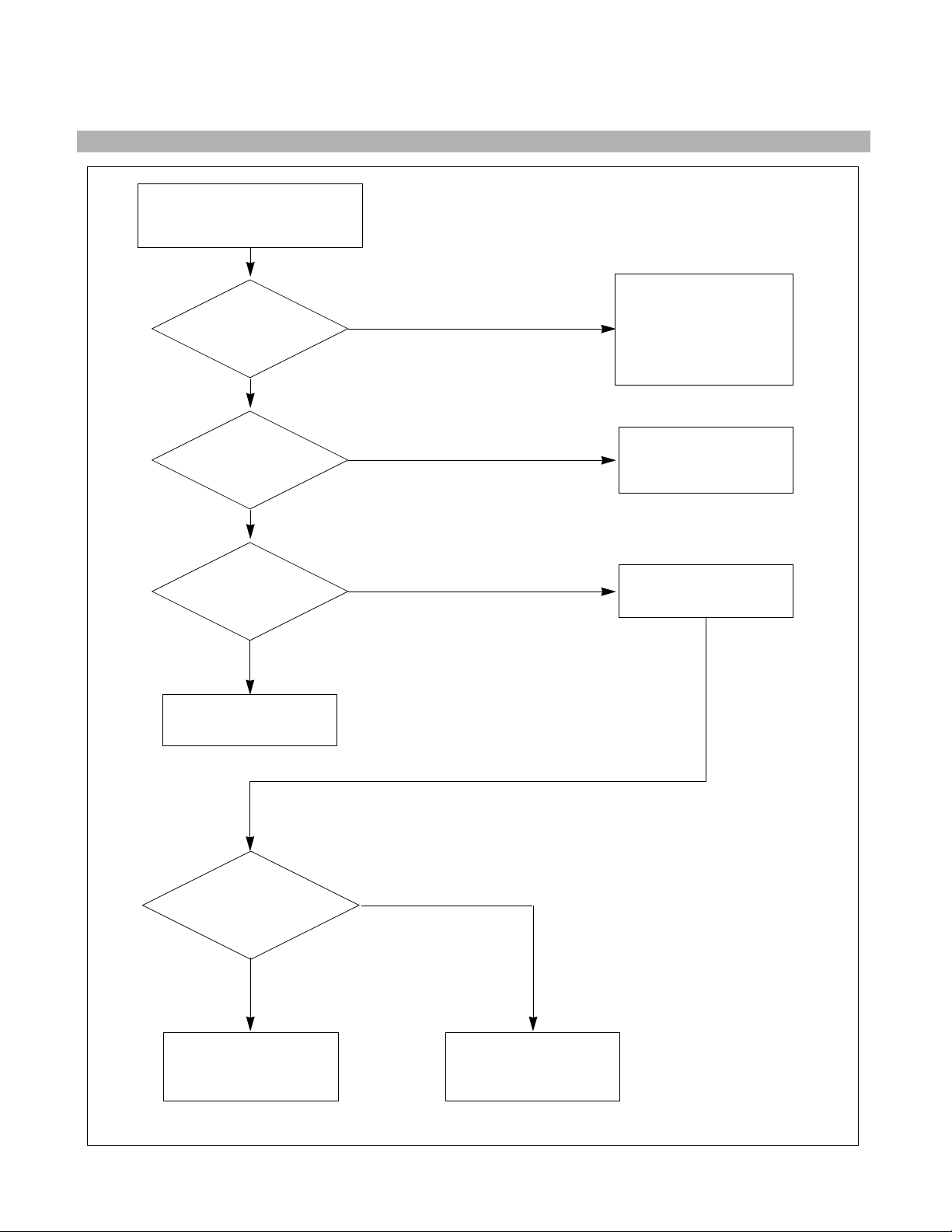
TROUBLESHOOTING GUIDE
1. NO POWER
CHECK U803.
CHECK
U501 PIN 8
VOLTAGE
(5V) ?
NO
NO POWER
(POWER INDICATOR OFF)
CHECK POWER
BOARD, AND FIND
OUT A SHORT POINT
AS OPENING
EACH POWER LINE
CHECK J707
VOLTAGE
PIN1&PIN2(12V)
PIN4(5V)?
NO
CHECK 5VS LINE
(OPEN CHECK)
CHECK
U805 Voltage
(5V) ?
NO
CHECK IIC LINE
CONNECTION
(U501, U502)
CHECK U201 VCC,
XTAL, RESET
IS U201 PIN12
VOLTAGE REPEATED
AS PULSE SHAPE ?
NO
YES
YES
YES
NO PROBLEM
NO
CHECK KEY CONTROL
CONNECTOR ROUTINE
Page 10

- 12 -
2. NO RASTER (OSD IS NOT DISPLAYED) – INVERTER
CHECK MICOM INV
ON/OFF PORT.
J705 PIN8
5V?
NO
NO RASTER
(OSD IS NOT DISPLAYED)
CHECK POWER BOARD
J705 PIN1
12V?
NO
1. CONFIRM BRIGHTNESS
OSD CONTRL STATE.
2. CHECK MICOM DIM-ADJ
PORT
J705 PIN7
5V?
NO
REPLACE
INVERTER ASS’Y
CHECK
PULSE AS
CONTACTING SCOPE
PROBE TO CAUTION LABEL.
(CONTACT PROBE TO
CAUTION LABEL.
CAN YOU SEE PULSE
AT YOUR
SCOPE?
NO
REPLACE CCFL LAMP
IN THE LCD MODULE
YES
YES
YES
YES
Page 11

- 13 -
1. CHECK PIN141, 142
SOLDERING CONDITION
2. CHECK X201
3. TROUBLE IN U201
U201
POWER PINS
3.3V?
NO
CHECK U802, U806
U201 PIN141, 142
OSCILLATE AS 20MHz?
CHECK CONNECTION LINE
FROM U201 TO U401
TROUBLE IN CABLE
OR LCD MODULE
CHECK U802
U401 PIN1
3.3V?
NO
YES
YES
YES
YES
3. NO RASTER (OSD IS NOT DISPLAYED) – gmZAN2
NO RASTER
(OSD IS NOT DISPLAYED)
U401
PIN31 IS 65MHz CLOCK?
PIN27 IS 48KHz H-SYNC?
PIN28 IS 60Hz V-SYNC?
PIN30 IS 48KHz DEN?
IS PULSE APPEARED
AT SIGNAL PINS?
NO
NO
Page 12

- 14 -
CHECK U802, U806
U201
POWER PIN
3.3V?
NO
1. CHECK PC
2. CHECK SIGNAL CABLE
& D-SUB CONNECTOR
LINE
CHECK
R,G,B INPUT?
U201 PIN 87, 91, 95
NO
CHECK H-SYNC LINE
(D-SUB→U701→MICOM
→U201 PIN150)
CHECK
H-SYNC INPUT
U201 PIN 150?
NO
YES
YES
YES
NO RASTER
(OSD IS DISPLAYED)
4. NO RASTER (OSD IS DISPLAYED) – gmZAN2
Page 13

- 18 -
EXPLODED VIEW PARTS LIST
Ref. No.
1
2
3
4-A
4-B
5
6
7
8
9
10
11
12
13
14
15
16
17
a
Part No.
3091TKL050A
6304FLP024A
3809TKL032A
3043TKK097A
3043TKK092A
4951TKS089B
6633TZA003H
or 6632Z-1507C
6871TPT223G
6871TST306A
3313TL5051A
4950TKK466A
6631T11012R
6871TST307A
4940TKT162B
6401TZZ025B
4950TKK337A
6852TAZ006F
6850TD9001A
332-068U
SAFETY MarkNote:
Description
CABINET ASSEMBLY, LM505J BRAND 3090TKL049A (M/MEDIA)
LCD(LIQUID CRYSTAL DISPLAY), LM150X07-B4 LG PHILPS TFT COLOR 15.0 INCH XGA LVDS SMM
BACK COVER ASSEMBLY, LM505J 3808TKL035A (M/MEDIA)
TILT SWIVEL ASSEMBLY, LB500J . (BASE)
TILT SWIVEL ASSEMBLYLB500J . .
METAL ASSEMBLY, FRAME MAIN(LM505J)
INVERTER ASSEMBLY, SAMSUNG LG1510 LG56AH
INVERTER ASSEMBLY, NMC 1507 15.1 12V (CHOI JEONG GYU)
PWB(PCB) ASSEMBLY, POWER, LB500J POWER TOTAL BRAND CL-38
PWB(PCB) ASSEMBLY, SUB, LM505J SOUND TOTAL BRAND CL-38
MAIN TOTAL ASSEMBLY LM505J BRAND CL-32
METAL, FRAME REAR(LM505J)
CONNECTOR ASSEMBLY, 20P H-H 120MM UL20276 PANEL LINK CABLE LM567D
PWB(PCB) ASSEMBLY, SUB, LM505J CONTROL TOTAL BRAND CL-38
KNOB, TACT CONTROL (LM505J/LM805L)9EA
SPEAKER ASSEMBLY, LM505J L284014 CSGAS07 SPEAKER ASSY 1W 4OHM
METAL, FIX SPEAKER (LM568E)
CORD, A/V DH-1560SP-BL UL2851#28 1560MM GRAY(85964) L/BLUE-LIME KSD LM568E
CABLE, D-SUB, UL 2990-9C(7.5) DT 1870MM GRAY(85964) BRAND DM
SCREW, PPB+3x8(MSWR/FZMW1)
Page 14

- 19 -
DATE: 2002. 7. 15.
*S *AL LOC. NO. PART NO. DESCRIPTION / SPECIFICATION
C201 0CC100CK41A 10PF 1608 50V 5% R/TP NP0
C202 0CC100CK41A 10PF 1608 50V 5% R/TP NP0
C203 0CC100CK41A 10PF 1608 50V 5% R/TP NP0
C205 0CK103CK51A 0.01UF 1608 50V 10% R/TP B(Y5P)
C207 0CK103CK51A 0.01UF 1608 50V 10% R/TP B(Y5P)
C208 0CK103CK51A 0.01UF 1608 50V 10% R/TP B(Y5P)
C209 0CK103CK51A 0.01UF 1608 50V 10% R/TP B(Y5P)
C210 0CK103CK51A 0.01UF 1608 50V 10% R/TP B(Y5P)
C211 0CK103CK51A 0.01UF 1608 50V 10% R/TP B(Y5P)
C212 0CK103CK51A 0.01UF 1608 50V 10% R/TP B(Y5P)
C215 0CK103CK51A 0.01UF 1608 50V 10% R/TP B(Y5P)
C216 0CK104CK56A 0.1UF 1608 50V 10% R/TP X7R
C223 0CC150CK41A 15PF 1608 50V 5% R/TP NP0
C224 0CC150CK41A 15PF 1608 50V 5% R/TP NP0
C225 0CC100CK41A 10PF 1608 50V 5% R/TP NP0
C226 0CC680CK41A 68PF 1608 50V 5% R/TP NP0
C230 0CC150CK41A 15PF 1608 50V 5% R/TP NP0
C254 0CK103CK51A 0.01UF 1608 50V 10% R/TP B(Y5P)
C255 0CK103CK51A 0.01UF 1608 50V 10% R/TP B(Y5P)
C256 0CK103CK51A 0.01UF 1608 50V 10% R/TP B(Y5P)
C257 0CK103CK51A 0.01UF 1608 50V 10% R/TP B(Y5P)
C258 0CK103CK51A 0.01UF 1608 50V 10% R/TP B(Y5P)
C259 0CK103CK51A 0.01UF 1608 50V 10% R/TP B(Y5P)
C261 0CC680CK41A 68PF 1608 50V 5% R/TP NP0
C262 0CC680CK41A 68PF 1608 50V 5% R/TP NP0
C269 0CK103CK51A 0.01UF 1608 50V 10% R/TP B(Y5P)
C270 0CK103CK51A 0.01UF 1608 50V 10% R/TP B(Y5P)
C271 0CK103CK51A 0.01UF 1608 50V 10% R/TP B(Y5P)
C401 0CK104CK56A 0.1UF 1608 50V 10% R/TP X7R
C402 0CK104CK56A 0.1UF 1608 50V 10% R/TP X7R
C403 0CK104CK56A 0.1UF 1608 50V 10% R/TP X7R
C404 0CK104CK56A 0.1UF 1608 50V 10% R/TP X7R
C405 0CK104CK56A 0.1UF 1608 50V 10% R/TP X7R
C501 0CK104CK56A 0.1UF 1608 50V 10% R/TP X7R
C502 0CC101CK41A 100PF 1608 50V 5% R/TP NP0
C503 0CC101CK41A 100PF 1608 50V 5% R/TP NP0
C504 0CK104CK56A 0.1UF 1608 50V 10% R/TP X7R
C505 0CC101CK41A 100PF 1608 50V 5% R/TP NP0
C506 0CC101CK41A 100PF 1608 50V 5% R/TP NP0
C507 0CK104CK56A 0.1UF 1608 50V 10% R/TP X7R
C508 0CK104CK56A 0.1UF 1608 50V 10% R/TP X7R
C509 0CK104CK56A 0.1UF 1608 50V 10% R/TP X7R
C510 0CK104CK56A 0.1UF 1608 50V 10% R/TP X7R
C512 0CC220CK41A 22PF 1608 50V 5% R/TP NP0
C513 0CC220CK41A 22PF 1608 50V 5% R/TP NP0
C514 0CH8106F611 10UF 16V M 85STD(CYL) R/TP
C515 0CC680CK41A 68PF 1608 50V 5% R/TP NP0
C516 0CK104CK56A 0.1UF 1608 50V 10% R/TP X7R
C701 0CK104CK56A 0.1UF 1608 50V 10% R/TP X7R
C702 0CC100CK41A 10PF 1608 50V 5% R/TP NP0
C703 0CC100CK41A 10PF 1608 50V 5% R/TP NP0
C704 0CC100CK41A 10PF 1608 50V 5% R/TP NP0
DATE: 2002. 7. 14.
*S *AL LOC. NO. PART NO. DESCRIPTION / SPECIFICATION
C705 0CC100CK41A 10PF 1608 50V 5% R/TP NP0
C706 0CK104CK56A 0.1UF 1608 50V 10% R/TP X7R
C707 0CC100CK41A 10PF 1608 50V 5% R/TP NP0
C712 0CC101CK41A 100PF 1608 50V 5% R/TP NP0
C713 0CK104CK56A 0.1UF 1608 50V 10% R/TP X7R
C715 0CH3105F946 1UF 16V Z F 2012 R/TP
C716 0CE107CH610 100UF SHL,SD 25V 20% BULK FL
C717 0CK104CK56A 0.1UF 1608 50V 10% R/TP X7R
C731 0CC680CK41A 68PF 1608 50V 5% R/TP NP0
C801 0CC102CK41A 1000PF 1608 50V 5% R/TP NP0
C802 0CK104CK56A 0.1UF 1608 50V 10% R/TP X7R
C813 0CC102CK41A 1000PF 1608 50V 5% R/TP NP0
C816 0CK104CK56A 0.1UF 1608 50V 10% R/TP X7R
C817 0CE107CF610 100UF SHL,SD 16V 20% BULK FL
C818 0CK104CK56A 0.1UF 1608 50V 10% R/TP X7R
C819 0CC102CK41A 1000PF 1608 50V 5% R/TP NP0
C820 0CE107CF610 100UF SHL,SD 16V 20% BULK FL
C821 0CK104CK56A 0.1UF 1608 50V 10% R/TP X7R
C822 0CK104CK56A 0.1UF 1608 50V 10% R/TP X7R
C823 0CC102CK41A 1000PF 1608 50V 5% R/TP NP0
C824 0CH8107F611 100UF 16V M 85STD(CYL) R/TP
C825 0CE107CF610 100UF SHL,SD 16V 20% BULK FL
C826 0CK104CK56A 0.1UF 1608 50V 10% R/TP X7R
C827 0CC102CK41A 1000PF 1608 50V 5% R/TP NP0
C828 0CK104CK56A 0.1UF 1608 50V 10% R/TP X7R
C829 0CC102CK41A 1000PF 1608 50V 5% R/TP NP0
C830 0CE107CF610 100UF SHL,SD 16V 20% BULK FL
C831 0CH8107F611 100UF 16V M 85STD(CYL) R/TP
C832 0CH8107F611 100UF 16V M 85STD(CYL) R/TP
C835 0CK104CK56A 0.1UF 1608 50V 10% R/TP X7R
D701 0DS226009AA KDS226 TP KEC SOT-23 80V 300MA
D702 0DS226009AA KDS226 TP KEC SOT-23 80V 300MA
D703 0DS226009AA KDS226 TP KEC SOT-23 80V 300MA
D704 0DS226009AA KDS226 TP KEC SOT-23 80V 300MA
D705 0DS226009AA KDS226 TP KEC SOT-23 80V 300MA
D706 0DS226009AA KDS226 TP KEC SOT-23 80V 300MA
D707 0DS301109AA MMBD301LT1 TP MOTOROLA SOT23 30
D708 0DS301109AA MMBD301LT1 TP MOTOROLA SOT23 30
D801 0DS181009AA KDS181 TP KEC SOT-23 80V 300M
D903 0DRGS00281A MBRF10H100CT GENERAL SEMICONDUC
D906 0DR206000AA MBRF2060CT BK G.I ITO220 60V 20
ZD501 0DZ910009FE UDZS 9.1B TP ROHM - - 9.1V - ZD701 0DZ560009DA UDZ S 5.6B TP ROHM-K SOD323 200
ZD702 0DZ560009DA UDZ S 5.6B TP ROHM-K SOD323 200
U201 0IPRPGA002A GMZAN2-160P GENESIS MICROCHIP 1
U401 0IPRPNV010A NT7181F NOVATEK 56P,TSSOP R/TP
U501 0IZZTSZ192A MYSON 42PIN BK OTP LM505J
U502 0ISG240860B M24C08W6 SGS-THOMSON 8SOP R/TP
REPLACEMENT PARTS LIST
CAUTION: BEFORE REPLACING ANY OF THESE COMPONENTS,
READ CAREFULLY THE SAFETY PRECAUTIONS IN THIS MANUAL.
* NOTE : S SAFETY Mark
AL ALTERNATIVE PARTS
MAIN BOARD
CAPACITORS
DIODEs
ICs
Page 15

DATE: 2002. 7. 14.
*S *AL LOC. NO. PART NO. DESCRIPTION / SPECIFICATION
U701 0IMO741420B MC74HCT14ADR2 14P,SOIC TP LEVEL
U702 0ISG240260A M24C02-MN6 SO8 TP 2K SERIAL IIC
U802 0IPMGKE011A KIA78D33F KEC DPAK R/TP 3.3V LD
U803 0ISS780500H KA78M05-R 3P,D-PAK TP 5V 0.5A R
U805 0IRH033000A BA033SFP P/MOLD-5 TP REGULATOR
U806 0IPMGON007A NCP1117ST25T3 ON SEMI SOT223 R/
L201 6210TCE001P HB-1S2012-121JT CERATECH 2012MM
L202 6210TCE001P HB-1S2012-121JT CERATECH 2012MM
L203 6210TCE001P HB-1S2012-121JT CERATECH 2012MM
L204 6210TCE001P HB-1S2012-121JT CERATECH 2012MM
L205 6210TCE001S HU-1M2012-121 CERATECH 2012MM R
L401 6210TCE001G HH-1M3216-501 CERATEC 3216MM R/
L701 6210TCE001S HU-1M2012-121 CERATECH 2012MM R
L702 6210TCE001P HB-1S2012-121JT CERATECH 2012MM
L703 6210TCE001P HB-1S2012-121JT CERATECH 2012MM
L704 6210TCE001P HB-1S2012-121JT CERATECH 2012MM
L705 6210TCE001P HB-1S2012-121JT CERATECH 2012MM
L706 6210TCE001P HB-1S2012-121JT CERATECH 2012MM
L707 6210TCE001P HB-1S2012-121JT CERATECH 2012MM
L708 6210TCE001S HU-1M2012-121 CERATECH 2012MM R
L710 6210TCE001G HH-1M3216-501 CERATEC 3216MM R/
L711 6210TCE001P HB-1S2012-121JT CERATECH 2012MM
L712 6210TCE001P HB-1S2012-121JT CERATECH 2012MM
L803 6210TCE001G HH-1M3216-501 CERATEC 3216MM R/
L804 6210TCE001G HH-1M3216-501 CERATEC 3216MM R/
BA201 6210TCE002B HB-4M3216-121JT CERATECH 3216MM
BA202 6210TCE002B HB-4M3216-121JT CERATECH 3216MM
BA203 6210TCE002B HB-4M3216-121JT CERATECH 3216MM
BA204 6210TCE002B HB-4M3216-121JT CERATECH 3216MM
BA205 6210TCE002B HB-4M3216-121JT CERATECH 3216MM
BA206 6210TCE002B HB-4M3216-121JT CERATECH 3216MM
Q501 0IKE704200J KIA7042AF SOT-89 TP 4.2V VOLTAG
Q502 0TR390409AE FAIRCHILD KST3904(LGEMTF) TP SO
Q505 0TR162309CA KSC1623 TP SAMSUNG SOT23 NPN E
Q506 0TR162309CA KSC1623 TP SAMSUNG SOT23 NPN E
Q701 0TR390409AE FAIRCHILD KST3904(LGEMTF) TP SO
Q702 0TR390409AE FAIRCHILD KST3904(LGEMTF) TP SO
R201 0RJ4701D677 4.7K OHM 1/10 W 5% 1608 R/TP
R202 0RJ4701D677 4.7K OHM 1/10 W 5% 1608 R/TP
R203 0RJ1000D677 100 OHM 1/10 W 5% 1608 R/TP
R204 0RJ1000D677 100 OHM 1/10 W 5% 1608 R/TP
R205 0RJ1000D677 100 OHM 1/10 W 5% 1608 R/TP
R206 0RJ2701D677 2.7K OHM 1/10 W 5% 1608 R/TP
R207 0RJ0332D677 33 OHM 1/10 W 5% 1608 R/TP
R208 0RJ1000D677 100 OHM 1/10 W 5% 1608 R/TP
R209 0RJ1000D677 100 OHM 1/10 W 5% 1608 R/TP
R210 0RJ1000D677 100 OHM 1/10 W 5% 1608 R/TP
R401 0RJ1002D677 10K OHM 1/10 W 5% 1608 R/TP
R403 0RJ1001D677 1K OHM 1/10 W 5% 1608 R/TP
R404 0RJ5601D477 5.6K OHM 1/10 W 1% 1608 R/TP
R501 0RJ4701D677 4.7K OHM 1/10 W 5% 1608 R/TP
R502 0RJ4701D677 4.7K OHM 1/10 W 5% 1608 R/TP
R503 0RJ4701D677 4.7K OHM 1/10 W 5% 1608 R/TP
DATE: 2002. 7. 14.
*S *AL LOC. NO. PART NO. DESCRIPTION / SPECIFICATION
R504 0RJ4701D677 4.7K OHM 1/10 W 5% 1608 R/TP
R505 0RJ1002D677 10K OHM 1/10 W 5% 1608 R/TP
R506 0RJ4701D677 4.7K OHM 1/10 W 5% 1608 R/TP
R507 0RJ1002D677 10K OHM 1/10 W 5% 1608 R/TP
R508 0RJ1002D677 10K OHM 1/10 W 5% 1608 R/TP
R509 0RJ4701D677 4.7K OHM 1/10 W 5% 1608 R/TP
R510 0RJ1000D677 100 OHM 1/10 W 5% 1608 R/TP
R511 0RJ4701D677 4.7K OHM 1/10 W 5% 1608 R/TP
R512 0RJ4701D677 4.7K OHM 1/10 W 5% 1608 R/TP
R513 0RJ1002D677 10K OHM 1/10 W 5% 1608 R/TP
R514 0RJ1000D677 100 OHM 1/10 W 5% 1608 R/TP
R515 0RJ1000D677 100 OHM 1/10 W 5% 1608 R/TP
R516 0RJ4701D677 4.7K OHM 1/10 W 5% 1608 R/TP
R517 0RJ4701D677 4.7K OHM 1/10 W 5% 1608 R/TP
R518 0RJ4701D677 4.7K OHM 1/10 W 5% 1608 R/TP
R519 0RJ4701D677 4.7K OHM 1/10 W 5% 1608 R/TP
R520 0RJ4701D677 4.7K OHM 1/10 W 5% 1608 R/TP
R521 0RJ4701D677 4.7K OHM 1/10 W 5% 1608 R/TP
R522 0RJ1500D677 150 OHM 1/10 W 5% 1608 R/TP
R523 0RJ0332D677 33 OHM 1/10 W 5% 1608 R/TP
R524 0RJ0332D677 33 OHM 1/10 W 5% 1608 R/TP
R525 0RJ1000D677 100 OHM 1/10 W 5% 1608 R/TP
R526 0RJ4701D677 4.7K OHM 1/10 W 5% 1608 R/TP
R527 0RJ4701D677 4.7K OHM 1/10 W 5% 1608 R/TP
R528 0RJ1000D677 100 OHM 1/10 W 5% 1608 R/TP
R529 0RJ1000D677 100 OHM 1/10 W 5% 1608 R/TP
R530 0RJ1000D677 100 OHM 1/10 W 5% 1608 R/TP
R531 0RJ1000D677 100 OHM 1/10 W 5% 1608 R/TP
R532 0RJ3301D677 3.3K OHM 1/10 W 5% 1608 R/TP
R533 0RJ1500D677 150 OHM 1/10 W 5% 1608 R/TP
R534 0RJ1500D677 150 OHM 1/10 W 5% 1608 R/TP
R535 0RJ3301D677 3.3K OHM 1/10 W 5% 1608 R/TP
R536 0RJ1004D677 1000000 OHM 1/10 W 5% 1608 R/TP
R537 0RJ4701D677 4.7K OHM 1/10 W 5% 1608 R/TP
R538 0RJ2202D677 22K OHM 1/10 W 5% 1608 R/TP
R539 0RJ1002D677 10K OHM 1/10 W 5% 1608 R/TP
R540 0RJ4701D677 4.7K OHM 1/10 W 5% 1608 R/TP
R541 0RJ1000D677 100 OHM 1/10 W 5% 1608 R/TP
R551 0RJ0000D677 0 OHM 1/10 W 5% 1608 R/TP
R561 0RJ0000D677 0 OHM 1/10 W 5% 1608 R/TP
R571 0RJ0000D677 0 OHM 1/10 W 5% 1608 R/TP
R581 0RJ0000D677 0 OHM 1/10 W 5% 1608 R/TP
R701 0RJ0752D677 75 OHM 1/10 W 5% 1608 R/TP
R702 0RJ4701D677 4.7K OHM 1/10 W 5% 1608 R/TP
R703 0RJ0752D677 75 OHM 1/10 W 5% 1608 R/TP
R704 0RJ1500D677 150 OHM 1/10 W 5% 1608 R/TP
R705 0RJ4700D677 470 OHM 1/10 W 5% 1608 R/TP
R706 0RJ0752D677 75 OHM 1/10 W 5% 1608 R/TP
R707 0RJ1500D677 150 OHM 1/10 W 5% 1608 R/TP
R708 0RJ1000D677 100 OHM 1/10 W 5% 1608 R/TP
R709 0RJ1000D677 100 OHM 1/10 W 5% 1608 R/TP
R711 0RJ0000D677 0 OHM 1/10 W 5% 1608 R/TP
R712 0RJ1000D677 100 OHM 1/10 W 5% 1608 R/TP
R713 0RJ1501D677 1.5K OHM 1/10 W 5% 1608 R/TP
R714 0RJ4701D677 4.7K OHM 1/10 W 5% 1608 R/TP
R715 0RJ1000D677 100 OHM 1/10 W 5% 1608 R/TP
R716 0RJ4701D677 4.7K OHM 1/10 W 5% 1608 R/TP
R717 0RJ4701D677 4.7K OHM 1/10 W 5% 1608 R/TP
R722 0RJ1001D677 1K OHM 1/10 W 5% 1608 R/TP
R733 0RJ1501D677 1.5K OHM 1/10 W 5% 1608 R/TP
R734 0RJ4701D677 4.7K OHM 1/10 W 5% 1608 R/TP
R805 0RJ1001D677 1K OHM 1/10 W 5% 1608 R/TP
- 20 -
COILs & COREs
TRANSISTOR
RESISTORs
Page 16

DATE: 2002. 7. 14.
*S *AL LOC. NO. PART NO. DESCRIPTION / SPECIFICATION
R807 0RJ1003D677 100K OHM 1/10 W 5% 1608 R/TP
R810 0RJ0221D677 2.2 OHM 1/10 W 5% 1608 R/TP
R811 0RJ0221D677 2.2 OHM 1/10 W 5% 1608 R/TP
RA501 0RHZTCZ001A 100 OHM 1/16 W 5% 3215 R/TP CHI
RA502 0RHZTCZ001A 100 OHM 1/16 W 5% 3215 R/TP CHI
X201 6202TST003F HC-49/SM5H KONY 20.0MHZ +/- 30
X501 6202TST003D HC-49/SM5H KONY CHIP 12 MHZ 30
C901 0CBZTBU002D 0.33UF D 275V K M/PP NI FM22.5
C902 0CKZTBU003D SC SAMWHA 250V 1000PF M BULK 7.
C903 0CKZTBU003D SC SAMWHA 250V 1000PF M BULK 7.
C905 0CZZTAB004B KMG SYE / SWE 400V 68UF 20% BUL
C906 0CK10201515 1000P 1KV K B TS
C907 0CE105EK638 1UF KMG 50V M FM5 TP 5
C908 0CE476EH638 47UF KMG 25V M FM5 TP 5
C909 181-288B MKT 100V 104JTR PHS26104
C911 0CE108EF630 1000UF KMG 16V M FM5 BULK
C914 0CE335EK638 3.3UF KMG 50V M FM5 TP 5
C916 181-288L MKT 100V 823JTR PHS26823
C918 0CE108EF630 1000UF KMG 16V M FM5 BULK
C920 0CKZTBU003C SC E 472M 14.0BW7 250V BK7.5 SA
C922 0CK10201515 1000P 1KV K B TS
C923 0CK10201515 1000P 1KV K B TS
D901 0DD400709CB UF4007 TP G.I DO204AL 1000V 1A
D904 0DR400409AB UF4004 TP G.I DO204AL 400V 1A 3
D908 0DZ620009AP P6KE200A GENERAL SEMICONDUCTOR
BD901 0DD260000BE D2SB60 SHINDENKEN
ZD901 0DZ750009AG MTZJ7.5B TP ROHM-K DO34 0.5W 7.
IC901 0IPMGPF004A TOP246F POWER INTEGRATION TO262
IC904 0ISS431000A KA431AZ (LM431AZ)
R901 0RD6803A609 680K OHM 1/2 W (7.0) 5% TA52
R902 0RD1004Q609 1M OHM 1/4 W (3.4) 5% TA52
R903 0RD1004Q609 1M OHM 1/4 W (3.4) 5% TA52
R904 0RD4704Q609 4.7M OHM 1/4 W (3.4) 5% TA52
R905 0RD4704Q609 4.7M OHM 1/4 W (3.4) 5% TA52
R906 0RX4702J609 47K OHM 1 W 5% TA52
R907 0RD0471Q609 4.70 1/4W(3 5% TA52
R908 0RD0681Q609 6.8 OHM 1/4 W (3.4) 5% TA52
R909 0RD1001Q609 1K 1/4W(3 5% TA52
R913 0RN1302F409 13K 1/6W 1% TA52
R917 0RD1201Q609 1.20K 1/4W(3 5% TA52
R918 0RD1000Q609 100 1/4W(3 5% TA52
R920 0RN1302F409 13K 1/6W 1% TA52
R921 0RN2701F409 2.70K 1/6W 1% TA52
R923 0RD1202Q609 12K 1/4W(3 5% TA52
F901 0FZZTTH001E TIME LAG HBC 2153.15MXE(LEAD),L
LF901 6200TZZ001B - 0 BK L/FILTER, 9MH,LG56BP
P901 6620TKB002C BCP031S-A,BAE EUN AC UNIVERSAL
PC901 0ILI817000E LTV-817M B 4P BK PHOTO COUPLER
T901 6170TMZ133A EER3016 1200 UH V-10PIN LG500J
TH901 6322A00002B SCK-102L THINKING 10OHM 20% 250
LED301 0DLLT0089AA LITEON LTL-1BEDJ-0C2 TP GREEN/Y
ZD301 0DZ560009CE MTZJ5.6B TP ROHM-K DO34 500MW
ZD302 0DZ560009CE MTZJ5.6B TP ROHM-K DO34 500MW
DATE: 2002. 7. 14.
*S *AL LOC. NO. PART NO. DESCRIPTION / SPECIFICATION
R301 0RD4701Q509 4.7K OHM 1/4 W (3.4) 2% TA52
R302 0RD4701Q509 4.7K OHM 1/4 W (3.4) 2% TA52
R303 0RD1001Q509 1K OHM 1/4 W (3.4) 2% TA52
R304 0RD1601Q509 1.6K OHM 1/4 W (3.4) 2% TA52
R305 0RD2701Q509 2.7K OHM 1/4 W(3.4) 2% TA52
R306 0RD6801Q509 6.8K OHM 1/4 W(3.4) 2% TA52
R307 0RD2701Q509 2.7K OHM 1/4 W(3.4) 2% TA52
R308 0RD2701Q509 2.7K OHM 1/4 W(3.4) 2% TA52
R309 0RD6801Q509 6.8K OHM 1/4 W(3.4) 2% TA52
SW301 140-058E SKHV10910B LGEC NON 12V 20A HOR
SW302 140-058E SKHV10910B LGEC NON 12V 20A HOR
SW303 140-058E SKHV10910B LGEC NON 12V 20A HOR
SW304 140-058E SKHV10910B LGEC NON 12V 20A HOR
SW305 140-058E SKHV10910B LGEC NON 12V 20A HOR
SW306 140-058E SKHV10910B LGEC NON 12V 20A HOR
SW307 140-058E SKHV10910B LGEC NON 12V 20A HOR
SW308 140-058E SKHV10910B LGEC NON 12V 20A HOR
SW309 140-058E SKHV10910B LGEC NON 12V 20A HOR
C901 0CK103CK51A 0.01UF 1608 50V 10% R/TP B(Y5P)
C902 0CK104CK56A 0.1UF 1608 50V 10% R/TP X7R
C903 0CE477EF610 470UF KMG,RD 16V 20% BULK FL
C904 0CE477EF610 470UF KMG,RD 16V 20% BULK FL
C905 0CE477EF610 470UF KMG,RD 16V 20% BULK FL
C906 0CH3105F946 1UF 16V Z F 2012 R/TP
C907 0CH3105F946 1UF 16V Z F 2012 R/TP
C908 0CH8107F611 100UF 16V M 85STD(CYL) R/TP
C909 0CK103CK51A 0.01UF 1608 50V 10% R/TP B(Y5P)
C910 0CK104CK56A 0.1UF 1608 50V 10% R/TP X7R
C911 0CK104CK56A 0.1UF 1608 50V 10% R/TP X7R
C912 0CH3105F946 1UF 16V Z F 2012 R/TP
C913 0CH3105F946 1UF 16V Z F 2012 R/TP
C914 0CC121CK41A 120PF 1608 50V 5% R/TP NP0
C915 0CE477EF610 470UF KMG,RD 16V 20% BULK FL
C916 0CC121CK41A 120PF 1608 50V 5% R/TP NP0
C917 0CK562CK51A 5600PF 1608 50V 10% R/TP B(Y5P)
C918 0CK154CH51A 0.15UF 1608 25V 10% R/TP B(Y5P)
C919 0CH3334K946 0.33UF 50V Z F(Y5V) 2012 R/TP
C920 0CH3334K946 0.33UF 50V Z F(Y5V) 2012 R/TP
C921 0CK154CH51A 0.15UF 1608 25V 10% R/TP B(Y5P)
C922 0CK562CK51A 5600PF 1608 50V 10% R/TP B(Y5P)
C923 0CH3473K946 47000PF 50V Z F 2012 R/TP
C924 0CH3473K946 47000PF 50V Z F 2012 R/TP
C925 0CC101CK41A 100PF 1608 50V 5% R/TP NP0
C926 0CC101CK41A 100PF 1608 50V 5% R/TP NP0
C927 0CH8106F611 10UF 16V M 85STD(CYL) R/TP
C928 0CH3224K946 0.22UF 50V Z F 2012 R/TP
C929 0CC102CK41A 1000PF 1608 50V 5% R/TP NP0
C930 0CC101CK41A 100PF 1608 50V 5% R/TP NP0
C931 0CH3473K946 47000PF 50V Z F 2012 R/TP
C932 0CH3473K946 47000PF 50V Z F 2012 R/TP
C933 0CK103CK51A 0.01UF 1608 50V 10% R/TP B(Y5P)
C934 0CH3224K946 0.22UF 50V Z F 2012 R/TP
C935 0CK104CK56A 0.1UF 1608 50V 10% R/TP X7R
C936 0CH8107F611 100UF 16V M 85STD(CYL) R/TP
C937 0CC102CK41A 1000PF 1608 50V 5% R/TP NP0
C938 0CC101CK41A 100PF 1608 50V 5% R/TP NP0
C939 0CH8107F611 100UF 16V M 85STD(CYL) R/TP
D901 0DS226009AA KDS226 TP KEC SOT-23 80V 300MA
D902 0DS226009AA KDS226 TP KEC SOT-23 80V 300MA
- 21 -
CONTROL BOARD
SOUND BOARD
POWER BOARD
OTHERs
Page 17

DATE: 2002. 7. 14.
*S *AL LOC. NO. PART NO. DESCRIPTION / SPECIFICATION
D903 0DS181009AA KDS181 TP KEC SOT-23 80V 300M
U901 0ISG749600A TDA7496L 20DIP BK 2W+2W AMP WIT
U902 0ISG744900B TDA7449 20DIP ST TONE CONT. AUD
U903 0ISS780800J KA78M08R 3P,D-PAK TP VOL. REGUL
L901 6210TCE001G HH-1M3216-501 CERATEC 3216MM R/
L902 6210TCE001P HB-1S2012-121JT CERATECH 2012MM
L903 6210TCE001P HB-1S2012-121JT CERATECH 2012MM
L904 6210TCE001G HH-1M3216-501 CERATEC 3216MM R/
L905 6210TCE001P HB-1S2012-121JT CERATECH 2012MM
L906 6210TCE001P HB-1S2012-121JT CERATECH 2012MM
L907 6210TCE001P HB-1S2012-121JT CERATECH 2012MM
L908 6210TCE001G HH-1M3216-501 CERATEC 3216MM R/
L909 6210TCE001P HB-1S2012-121JT CERATECH 2012MM
L920 6140TBZ016G - GET DR12*6.7,1.0MH,LM505J
Q901 0TR387500AA CHIP 2SC3875S(ALY) KEC
R901 0RJ0471D677 4.7 OHM 1/10 W 5% 1608 R/TP
R902 0RJ0471D677 4.7 OHM 1/10 W 5% 1608 R/TP
R903 0RJ1000D677 100 OHM 1/10 W 5% 1608 R/TP
R904 0RJ1000D677 100 OHM 1/10 W 5% 1608 R/TP
R905 0RJ1202D677 12K OHM 1/10 W 5% 1608 R/TP
R906 0RJ1000D677 100 OHM 1/10 W 5% 1608 R/TP
R907 0RJ4701D677 4.7K OHM 1/10 W 5% 1608 R/TP
R908 0RJ2001D677 2K OHM 1/10 W 5% 1608 R/TP
R909 0RJ1002D677 10K OHM 1/10 W 5% 1608 R/TP
R910 0RJ4701D677 4.7K OHM 1/10 W 5% 1608 R/TP
R911 0RJ2701D677 2.7K OHM 1/10 W 5% 1608 R/TP
R912 0RJ1000D677 100 OHM 1/10 W 5% 1608 R/TP
R913 0RJ1000D677 100 OHM 1/10 W 5% 1608 R/TP
R914 0RJ2002D677 20000 OHM 1/10 W 5% 1608 R/TP
R915 0RJ2002D677 20000 OHM 1/10 W 5% 1608 R/TP
R916 0RJ2002D677 20000 OHM 1/10 W 5% 1608 R/TP
R917 0RJ4701D677 4.7K OHM 1/10 W 5% 1608 R/TP
R918 0RJ2001D677 2K OHM 1/10 W 5% 1608 R/TP
R919 0RJ1002D677 10K OHM 1/10 W 5% 1608 R/TP
R920 0RJ2202D677 22K OHM 1/10 W 5% 1608 R/TP
R921 0RJ2702D677 27K OHM 1/10 W 5% 1608 R/TP
R922 0RJ1002D677 10K OHM 1/10 W 5% 1608 R/TP
R923 0RJ2202D677 22K OHM 1/10 W 5% 1608 R/TP
R924 0RJ2702D677 27K OHM 1/10 W 5% 1608 R/TP
J902 6612F00005D DJ-SW3P-LM KSD STERO R/A LIME S
J903 6612F00001C DJ-S360LB KSD STERO R/A LIGHT B
- 22 -
Page 18

PIN CONFIGURATION
- 23 -
MYSON 42PIN BK
DA2/P5.2
DA1/P5.1
DA0/P5.0
NC
NC
NC
RST
VDD
VSS
X2
X1
ISDA/P3.4/T0
ISCL/P3.5/T1
STOUT/P4.2
P2.2/AD2
P1.0
P1.1
P1.2
P1.3
P1.4
P3.2/INT0
VSYNC
HSYNC
DA3/P5.3
DA4/P5.4
DA5/P5.5
DA8/HALFH
DA9/HALFV
HBLANK/P4.1
VBLANK/P4.0
DA7/HCLAMP
DA6/P5.6
P2.6/DA12
P2.5/DA11
P2.4/DA10
HSCL/P3.0/Rxd
HSDA/P3.1/Txd
P2.0/AD0
P2.1/AD1
P1.7
P1.6
P1.5
42
41
40
39
38
37
36
35
34
33
32
31
30
29
28
27
26
25
24
23
22
1
2
3
4
5
6
7
8
9
10
11
12
13
14
15
16
17
18
19
20
21
Page 19

- 24 -
NO
1
2
3
4
5
6
7
8
9
10
11
12
13
14
15
16
17
18
19
20
21
22
23
24
25
26
27
28
29
30
31
32
33
34
35
36
37
38
39
40
41
42
SYMBOL
DA2/P5.2
DA1/P5.1
DA0/P5.0
NC
NC
NC
RST
VDD
VSS
X2
X1
ISDA/P3.4/T0
ISCL/P3.5/T1
STOUT/P4.2
P2.2/AD2
P1.0
P1.1
P3.2/INT0
P1.2
P1.3
P1.4
P1.5
P1.6
P1.7
P2.1/AD1
P2.0/AD0
HSDA/P3.1/Txd
HSCL/P3.0/Rxd
P2.4/DA10
P2.5/DA11
P2.6/DA12
DA6/P5.6
DA7/HCLAMP
VBLANK/P4.0
HBLANK/P4.1
DA9/HALFH
DA8/HALFH
DA5/P5.5
DA4/P5.4
DA3/P5.3
HSYNC
VSYNC
Function
PWM DAC output/General purpose I/O
PWM DAC output/General purpose I/O
PWM DAC output/General purpose I/O
Active High Reset
Positive Power Supply
Ground
Oscillator output
Oscillator input
Master IIC data/General Purpose I/O / T0
Master IIC clock/General Purpose I/O / T1
Self-test video output / General purpose Output
General purpose I/O / ADC Input
General purpose I/O
General purpose I/O
General purpose Input / INTO
General purpose I/O
General purpose I/O
General purpose I/O
General purpose I/O
General purpose I/O
General purpose I/O
General purpose I/O / ADC Input
General purpose I/O / ADC Input
Slave IIC data / General purpose I/O / Txd
Slave IIC clock / General purpose I/O / Rxd
General purpose I/O / PWM DAC output
General purpose I/O / PWM DAC output
General purpose I/O / PWM DAC output
PWM DAC Output / General Purpose I/O
PWM DAC output / Hsync clamp pulseoutput
Vertical blank /General purpose Output
Horizontal blank / General purpose Output
PWM DAC output / vsync half req. Output
PWM DAC output / hsync half freq. Output
PWM DAC output / General purpose I/O
PWM DAC output / General purpose I/O
PWM DAC output / General purpose I/O
Horizontal SYNC or Composite SYNC Input
Vertical SYNC Input
I/O
I/O
I/O
I/O
I
O
I
I/O
I/O
O
I/O
I/O
I/O
I
I/O
I/O
I/O
I/O
I/O
I/O
I/O
I/O
I/O
I/O
I/O
I/O
I/O
I/O
O
O
O
O
O
I/O
I/O
I/O
I
I
Act Reset
PIN FUNCTION
Page 20

- 25 -
gmZAN2-160P GENESIS MICROCHIP
121
122
123
124
125
126
127
128
129
130
131
132
133
134
135
136
137
138
139
140
141
142
143
144
145
146
147
148
149
150
151
152
153
154
155
156
157
158
159
160
OSD_DATA3
OSD_FSW
MFB11
MFB10
DVDD
DVSS
DAC_DGNDA
DAC_DVDDA
PLL_DVDDA
Reserved
PLL_DGNDA
SUB_DGNDA
SUB_SGNDA
PLL_SGNDA
Reserved
PLL_SVDDA
DAC_SVDDA
DAC_SGNDA
SVDD
SVSS
TCLK
XTAL
PLL_RVDDA
PLL_RGNDA
Reserved
SUB-RGNDA
CVSS5
VSYNC
SYN_VDD
HSYNC/CS
SYN_VSS
Reserved
STI-TM1
STI-TM2
SCAN_IN1
Reserved
SCAN_IN2
SRVSS2
SCAN_OUT1
SCAN-OUT2
CVSS1
Reserved
PSCAN
Reserved
CVSS!A
PD47
PD46
RVSS1
PD45
PD44
SRVDD1
RVDD1
PD43
PD42
PD41
PD40
PD39
SRVSS1
PD38
PD37
SRVDD2
PD36
PD35
PD34
PD33
PD32
PD31
PD30
PD29
RVSS2
PD28
PD27
RVDD2
PD26
PD25
PD24
PD23
PD22
PD21
RVDD2A
OSD_DATA2
OSD_DATA1
OSD_DATA0
OSD_CLK
OSD_VRFF
OSD_HREF
CVSS4
MFB0
MFB1
MFB2
MFB3
MFB4
RVDD3A
MFB5
MFB6
MFB7
MFB8
HCLK
MFB9
IRQ
PRESETn
HDATA
HFS
N/C
ADC_RVDDA
RED+
RED-
ADC_RGNDA
ADC_GVDDA
GREEN+
GREEN-
ADC_GGNDA
ADC_BVDDA
BLUE+
BLUE-
ADC_BGNDA
ADC_VDDA
Reserved
ADC_GNDA
SUB_GNDA
ADC_GND1
ADC_VDD1
ADC_GND2
ADC_VDD2
PPWR
PBIAS
PHS
PVS
CVSS3
PD0
PD1
PD2
PD3
PD4
PD5
RVDD3
PD6
PD7
PD8
RVSS4
RVDD2B
CVSS2A
CVDD2
PD9
PD10
PD11
PD12
PD13
PD14
PD15
PD16
RVSS3
PD17
PD18
PD19
PCLKB
PCLKA
PDISPE
PD20
CVSS2
120
119
118
117
116
115
114
113
112
111
110
109
108
107
106
105
104
103
102
101
100
99989796959493929190898887868584838281
123456789
10111213141516171819202122232425262728293031323334353637383940
80
79
78
77
76
75
74
73
72
71
70
69
68
67
66
65
64
63
62
61
60
59
58
57
56
55
54
53
52
51
50
49
48
47
46
45
44
43
42
41
gmZAN2(160-Pin PQFP)
Page 21

- 26 -
ADC_VDD
CVDD
RVDDA
RGNDA
SVDDA
SGNDA
DVDDA
DGNDA
Even Data
24
24
+12V
+5/3.3V
Pbias
Pbias
Odd Data
PCLKA
Red
Blue
Green
Hsync
To Clock
Generator
OSD-FSW
On-Screen
Display
Controller
ADC
Host Interface
Video Connector
Panel Interface
TFT Panel
Clock Generator
MPU with
EEPROM
IRQ
HES
HCLK
HDATA
MFBs
RESETn
OSD-CLK
OSD-HREF
OSD-VREF
R+,G+,B+
4
12
PDISPE
CVSS
PHS
PVS
TCLK
OSC
ADC_GNS
gmZAN2 Core
System-level Block Diagram
Block Diagram for gmZAN2
Analog
RGB
MCU
Triple
ADC
Host
interface
Source
Timing
Measurement
/Generation
Scaling
Engine
On-Screen
Display
Control
Gamma
Control
(CLUT)
Dother
+
Clock
Recovery
Reference
Generator
Clock
Panel
Timing
Control
Pixel
Clock
Panel
Page 22

- 27 -
MC74HCT14ADR2 14P
V
A1
Y1
AS
A2
Y6
Y2
A5
A3
Y5
Y3
A4
GND
Y4
CC
1
2
3
4
5
6
7
14
13
12
11
10
9
8
PIN CONFIGURATION
BLOCK DIAGRAM
12
A1 Y1
34
A2 Y2
56
A3 Y3
98
A4 Y4
11 10
A5 Y5
13 12
A6
PIN 14=V
CC
PIN 7=GND
Y6
Page 23

SCHEMATIC DIAGRAM
- 28 -
1. GMZAN2
Page 24

- 29 -
2. LVDS
/ 8
Page 25

- 30 -
3. MICOM
Page 26

- 31 -
4. POWER
Page 27

- 32 -
5. CONNECTOR & JACKS
Page 28

- 33 -
6. KEY CONTROL
Page 29

- 34 -
7. AUDIO
Page 30

- 35 -
8. POWER
 Loading...