

Page 1

Service Manual
(LM40/50)
LG Electronics
0
Page 2

Contents
Ch 1. Service information
Ch 2. Locations
Ch 3. System information
· Specification
· Model configuration
· System Block Diagram
· Fn key combinations
· Status indicators
· BIOS Flash
· BIOS Setup
Ch 4. Symptom-to-part index
· Power system checkout
· Numeric error codes
· Error messages
· LCD-related symptoms
· Indeterminate problems
Ch 5. Removing and replacing a part (FRU)
Ch 6. Part list
· Part list
· Exploded view
1
Page 3
Ch1. Service information
Chapter 1. Service information
1-1. Important service information
Strategy for replacing parts (FRU-Field Replaceable Units)
Before replacing parts
Make sure that latest BIOS and drivers are installed before replacing any parts (FRUs) listed in this
Use the following strategy to prevent unnecessary expense for replacing and servicing parts
1. If you are instructed to replacing a part but the replacement does not correct the problem, reinstall the
original part before you continue.
2. Some computers have both a processor board and system board. If you are instructed to replace either
the processor board or the system board, and replacing one of them does not correct the problem,
reinstall that board, and then replace the other one.
3. If an adapter or device consists of more than one part, any of the parts (FRUs) may be the cause of the
error. Before replacing the adapter or device, remove the parts (FRUs), one by one, to see if the
symptoms change. Replace only the part that changed the symptoms.
Caution
The BIOS configuration on the computer you are servicing may have been customized.
Running Automatic Configuration my alter th e setti ng s. Note the current config urati on setti ng s;
then, when service has been completed, verify that those settings remain in effect.
Strategy for replacing a hard-disk drive
You have to get a User’s approval before formatting or replacing a hard-disk drive. You must let the User
know that the u s er is responsible for the loss data
Caution
The drive startup sequence in the computer you are servicing may have been changed. Be
extremely careful during write operations such as copying, saving, or formatting. If you select an
incorrect drive, data or programs can be overwritten.
2
Page 4
1-2. Safety notices
Warning
Before the computer is powered-on after part (FRU) replacement, make sure all screws, springs,
and other small parts are in place and are not left loose inside the computer. Verify this by
shaking the computer and listening for rattling sounds. Metallic parts or metal flakes can cause
electrical shorts.
Warning
some standby batteries contain a small amount of nickel and cadmium. Do not disassemble
a standby battery, recharge it, throw it into fire or water, or short-circuit it. Dispose of the battery
as required by local ordinances or regulations. Use only the battery in the appropriate parts
listing. Use of an incorrect battery can result in ignition or explosion of the battery
Warning
Ch1. Service information
The battery pack contains small amounts of nickel. Do not disassemble it, throw it into fire or
water, or short-circuit it. Dispose of the battery pack as required by local ordinances or
regulations. Use only the battery in the appropriate parts listing when replacing the battery pack.
Use of an incorrect battery can result in ignition or explosion of the battery.
Warning
If the LCD breaks and the fluid from inside the LCD gets into your eyes or on your hands,
immediately was the affected areas with water for at least 15 minutes. Seek medical care if any
symptoms from the fluid are present after washin g.
Warning
To avoid shock, do not remove the plastic cover that protects the lower part of the inverter card.
Warning
Though the main batteries have low voltage, a shorted or grounded battery can produce enough
current to burn personnel or combustible materials.
Warning
Before removing any part (FRU), turn off the computer, unplug all power cords from electrical
outlets, remove the battery pack, and then disconnect any interconnecting cables.
3
Page 5

Ch1. Service information
1-3. Safety information
General safety
Follow these rules to ensure general safety
· Observe good housekeeping in the area of the machines during and after maintenance.
· When lifting any heavy object
1. Ensure you can stand safely without slipping.
2. Distribute the weight of the object equally between your feet.
3. Use a slow lifting force. Never move suddenly or twist when you attempt to lift.
4. Lift by standing or by pushing up with your leg muscles
(This action removes the strain from the muscles in your back.)
· Do not attempt to lift any object weights more then 16kg(35lb) or object that you think are too heavy for you.
· Do not perform any action that causes hazards to the customer, or that makes the equipment unsafe.
· Before you start the machine, ensure that other service representatives and the customer’s personnel are
not in a hazardous position.
· Place removed covers and other parts in a safe place, away from all personnel, while you are servicing the
machine.
· Keep your tool box away from walk areas so that other people will not trip over it.
· Do not wear loose clothing that can be trapped in the moving parts of a machine. Make sure that your
sleeves are fastened or rolled up above your elbows. If your hair is long, fasten it.
· Insert the ends of your necktie or scarf inside clothing or fasten it with a nonconductive clip, approximately
8 centimeters(3 inches) from the end.
· Do not wear jewelry, chains, metal-frame eyeglasses, or metal fasteners for you clothing.
· Wear safety glasses when you are hammering, drilling, soldering, cutting wire, attaching springs, using
solvents, or working in any other conditions that might be hazardous to your eyes.
· After service, reinstall all safety shields, guards, labels, and ground wires. Replace any safety device that
is worn or defective.
· Reinstall all covers correctly before returnin g the machine to the customer.
Caution
Metal objects are good electrical conductors.
4
Page 6
Ch1. Service information
Electrical safety
Observe the following rules when working on electrical equipment.
Important
Use only approved tools and test equipment. Some hand tools have handles covered with a soft
material that does not insulate you when working with live electrical currents.
Many customers have, near their equipment, rubber floor mats that contain small conductive
fibers to decrease electrostatic discharges. Do not use this type of mat to protect yourself from
electrical shock.
· Find the room emergency power-off switch, disconnecting switch, or electrical outlet. If an electrical outlet.
If an electrical accident occurs, you can then operate the switch or unplug the power cord quickly.
· Do not work alone under hazardous conditions or near equipment that has hazardous voltages.
· Disconnect all power before
1. Performing a mechanical inspection
2. Working near power supplies
3. Removing or installing main units
· Before you start to work on the machine, unplug the power cord. If you cannot unplug it, ask the customer
to power-off the wall box that supplies power to the machine and to lock the wall box in the off position.
· If you need to work on a machine that has exposed electrical circuits, observe the following precautions :
Ensure that another person, familiar with the power-off controls, is near you.
Caution
Another person must be there to switch off the power, if necessary.
· Use only one hand when working with powered-on electrical equipment. Keep the other hand in your
pocket or behind your back
Caution
An electrical shock can occur only when there is a complete circuit. By observing the above rule,
you may prevent a current from through your body.
· When using testers, set the controls correctly and use the approved probe leads and accessories for that
tester
5
Page 7

Ch1. Service information
· Stand on suitable rubber mats (obtained locally, if necessary) to insulate you from grounds such as metal
floor strips and machine frames.
· Observe the special safety precautions when you work with very high voltages. These instructions are in
the safety sections of maintenance information. Use extreme care when measuring high voltages.
· Regularly inspect and maintain your electrical hand tools for safe operational condition.
· Do not use worn or broken tools and testers.
· Never assume that power has been disconnected from a circuit. First check that it has been powered off.
· Always look carefully for possible hazards in your work area. Examples of these hazards are moist floors,
non-grounded power extension cables, power surges, and missing safety grounds.
· Do not touch live electrical circuits with the reflective surface of a plastic dental mirror. The surface is
conductive such touching can cause personal injury and machine damage.
· Do not service the following parts with the power on when they are removed from their normal operating
places in a machine.
1. Power supply units
2. Pumps
3. Blowers and fans
4. Motorgenerators
and similar units. (This practice ensure correct grounding of the units.)
· If an electrical accident occurs
1. Use caution ; do not become a victim of yourself.
2. Switch off power.
3. Send another person to get medical aid.
6
Page 8

Ch1. Service information
Safety inspection guide
The purpose of this inspection guide is to assist you in identifying potentially unsafe conditions.
As each machine was designed and built, required safety items were installed to protect users and service
personnel from injury. This guide addresses only those items. You should use good judgment to identify
potential safety hazards due to attachment of non-LG features or options not covered by this inspection
guide.
If any unsafe conditions are present, you must determine how serious the apparent hazard could be and
whether you can continue without first correcting the problem.
· Consider these conditions and the safety hazards they present
1. Electrical hazards, especially primary power (primary voltage on the frame can cause serious or fatal
electrical shock)
2. Mechanical hazards, such as loose or missing hardware
Refer to the following checklist and begin the checks with the power off, and the power cord disconnected.
· Checklist
1. Check exterior covers for damage (loose, broken, or sharp edges)
2. Power off the computer. Disconnect the power cord.
3. Check the power cord for :
a. A third-wire ground connector in good condition. Use a meter to measure third-wire ground continuity
for 0.1 or less between the external ground pin and frame ground.
b. The power cord should be the type specified in the parts list.
c. Insulation must not be frayed or worn.
4. Remove the cover.
5. Check for any obvious non-LG alterations. Use good judgment as to the safety of any non-LG
alterations.
6. Check inside the unit for any obvious unsafe conditions, such as metal filings, contamination, water or
other liquids, or signs of fire or smoke damage.
7. Check for worn, frayed, or pinched cables.
8. Check that the power-supply cover fasteners (screw or rivets) have not been removed or tampered with.
7
Page 9

Ch1. Service information
Handling devices that are sen sitive to electrostatic discharge
Any computer part containing transistors or integrated circuits (ICs) should be considered sensitive to
electrostatic discharge (ESD). ESD damage can occur when there is a difference in charge between
objects. Protect against ESD damage by equalizing the charge so that the machine, the part, the work mat,
and the person handling the part are all at the same charge.
Note
Use product-specific ESD procedures when they exceed the requirements noted here.
Make sure that the ESD protective devices you use have been certified (ISO9000) as fully effective.
· When handling ESD-sensitive parts :
1. Keep the parts in protective packages until they are inserted into the product.
2. Wear a grounded wrist strap against your skin to eliminate static on your body.
3. Prevent the part from touching your clothing. Most clothing retains a charge even when you are wearing
a wrist strap.
4. Use the black side of a grounded work mat to provide a static-free work surface. The mat is especially
useful when handling ESD-sensitive devices.
5. Select a grounding system, such as those listed below, to provide protection that meets the specific
service requirement.
Note
The use of a grounding system is desirable but not required to protect against ESD damage.
a. Attach the ESD ground clip too any frame ground, ground braid, or green-wire ground.
b. Use an ESD ground or reference point when working on a double-insulated or battery-operated
system. You can use coax or connector-outside shells on these systems.
c. Use the round ground-prong of the AC plug on AC-operated computers.
Grounding requirements
Electrical grounding of the computers is required for operator safety and correct system function.
Proper grounding of the electrical outlet can be verified by a certified electrician.
8
Page 10
Ch1. Service information
1-4. Laser compliance statement
When a CD-ROM drive, DVD drive or the other laser product is installed, note the following :
Caution
Use of controls or adjustments or performance of procedures other than those specified here in
might result in hazardous radiation exposure.
Opening the CD-ROM drive, DVD-ROM drive or the other optical storage device could result in exposure
to hazardous laser radiation.
There are no serviceable parts inside those drives. Do not open
Danger
Emits visible and invisible laser radiation when open. Do not stare into the beam , do not view
directly with optical instruments, and avoid direct exposure to the bean.
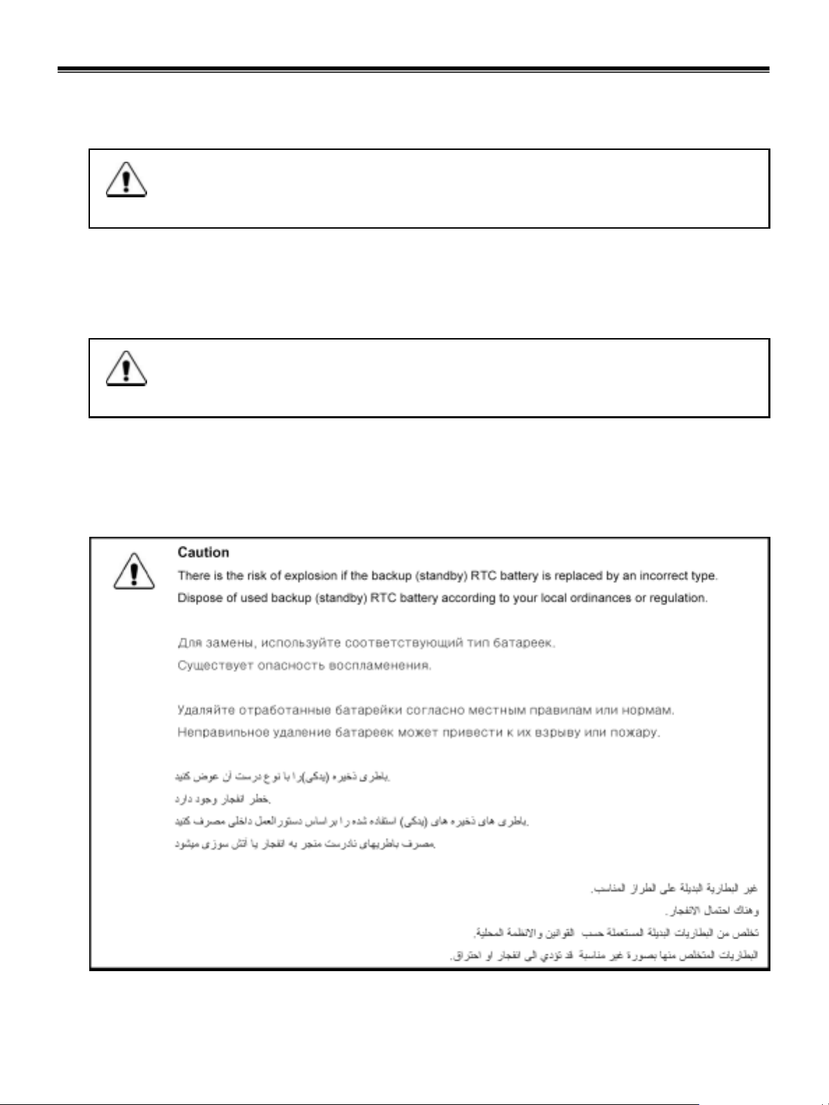
1-5. Backup (Standby) RTC battery safety information
When replacing or disposing of the backup (standby) RTC battery, note the following :
9
Page 11

Ch1. Service information
1-6. Read this first
Before you go to the checkout guide, be sure to read this section.
Important Notes
· Only trained personnel certified by LG should service the computer.
· Read the entire FRU removal and replacement page before replacing any FRU.
· Use new nylon-coated screws when you replace FRUs.
· Be extremely careful during such write operations as copying, saving, formatting.
Drives in the computer that you are servicing sequence might have been altered. If you selected an
incorrect drive, data or programs might be overwritten.
· Replace FRUs only for the correct mode.
· When you replace a FRU, make sure the model of the machine and the FRU part number are correct by
referring to the FRU parts list.
· A FRU should not be replaced because of a single, irreproducible failure. Single failures can occur for a
variety of reasons that have nothing to do with a hard ware defect, such as cosmic radiation,
electrostatic discharge, or software errors.
· Consider replacing a FRU only when a problem recurs. If you suspect that a FRU is defective, clear the
error log and run the test again. If the error does not recur, do not replace the FRU.
· Be careful not to replace a non-defective FRU.
What to do first
You must fill out the record form first.
During the warranty period, the customer may be responsible for repair costs if the computer damage was
caused by misuse, accident, modification, unsuitable physical or operating environment, or improper
maintenance by the customer. The following list provides some common items that are not covered under
warranty and some symptoms that might indicate that the system was subjected to stress beyond normal
use. Before checking problems with computer, determine whether the damage is covered under the
warranty by referring to the following :
10
Page 12

Ch1. Service information
The followings are not covered unde r warranty :
· CD panel cracked from the application of excessive force or from being dropped
· Scratched (cosmetic) parts
· Distortion, deformation, or discoloration of the cosmetic p arts
· Cracked or broken plastic parts, broken latches, broken pins, or broken connectors caused by excessive
force
· Damage caused by liquid spilled into system
· Damage caused by improper insertion of a PC Card or the installation of an incompatible card
· Damage caused foreign material in the diskette drive
· Diskette drive damage caused by pressure on the diskette drive cover or by the insertion of a diskette
with multiple labels
· Damaged or bent diskette eject button
· Fusses blown by attachment of a non-supported device
· Forgotten computer password (making the computer unusable)
· Sticky keys caused by spilling a liquid onto the keyboard
The following symptoms might indicate dam ag e caused by non-warranted acti vities :
· Missing parts might be a symptom of unauthorized service or modification.
· If the spindle of a hard-disk drive becomes noisy, it may have been subjected to excessive force, or
dropped.
11
Page 13
Chapter 2. Locations
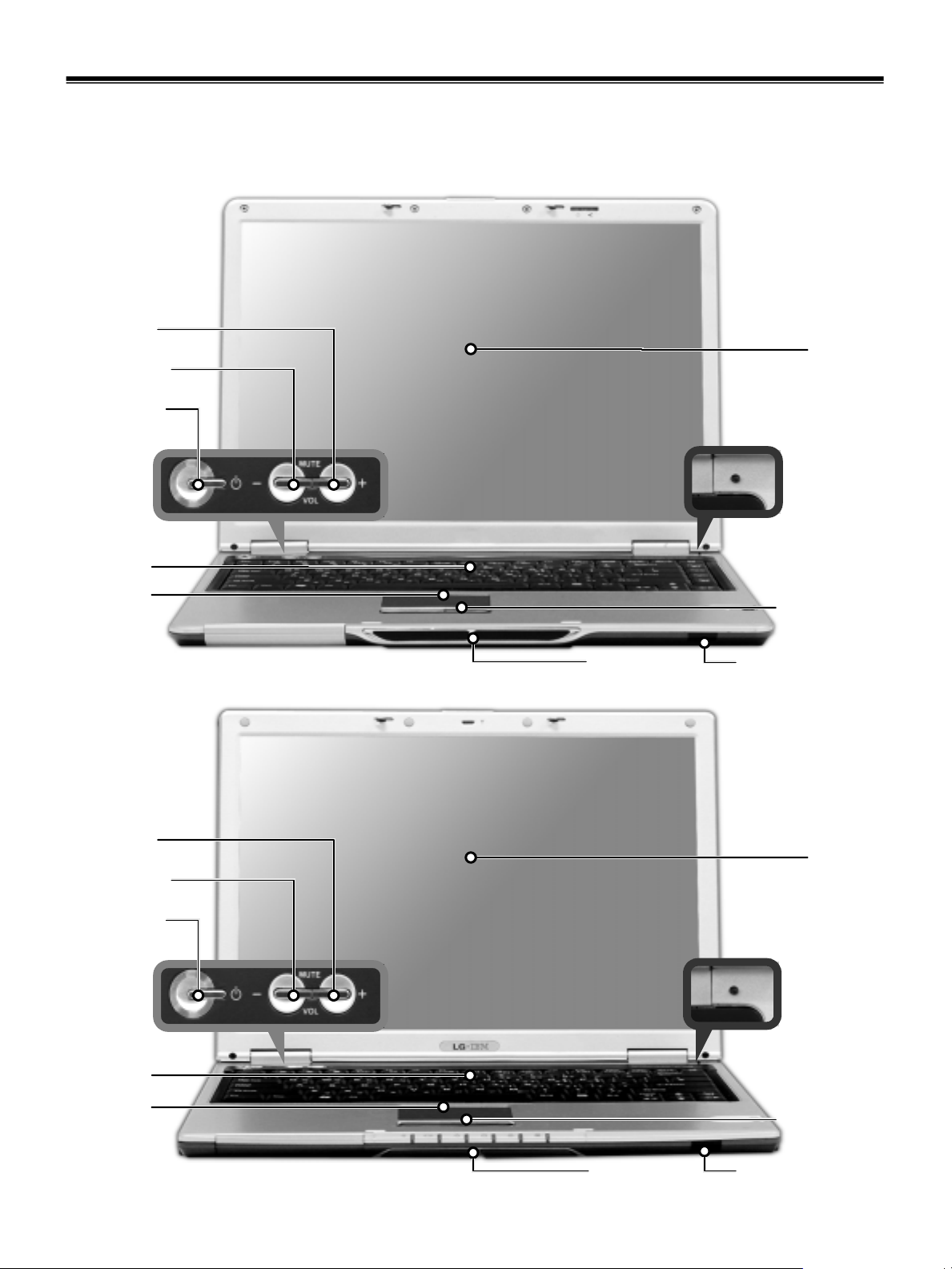
Front view (15”)
Volume Up
Volume Down
Power switch
Ch2. Locations
LCD
Power-saving mode switch
Keyboard
TouchPad
Front view (14.1”)
Volume Up
Volume Down
Power switch
Built-in speakers
Power-saving mode switch
TouchPad button
IrDA port
LCD
Keyboard
TouchPad
12
Built-in speakers
TouchPad button
IrDA port
Page 14
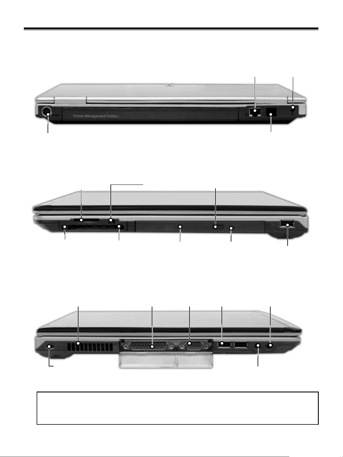
Rear view (15”/14.1”)
Ch2. Locations
Power jackEthernet port
S-Video
Left view (15”/14.1”)
SD memory Card slot
PC card eject button
PC card slot
Right view (15”/14.1”)
IEEE1394 port
ODD
ODD tray open button
Emergency eject hole
Modem port
USB port
VGA portParallel portFan louvers
Key hole (Kensington Lock)
USB port
Microphone jack
Headphone jack / S-PDIF
Security key hole (Kensington Lock)
User can attach a separately purchased chain lock into the security keyhole and connect it to a fixed object
to prevent a notebook theft
13
Page 15

Ch3. System information
Chapter 3. System information
Specification
•CPU
· Banias 1.3 ~ 1.7 GHz / Dothan 1.7 GHz
·FCPGA
• Main Chipset & Graphic
· Intel ODEM + ICH4
· Intel Montara GME (Graphic Controller Integrated)
· ATi M9+ w/32MB VRAM
· ATi M10 w/64MB VRAM
• Memory
· 2SODIMM – Up to 2GB
· DDR200/266/333 Capable
• HDD
· 2.5” 9.5mm 40/60/80GB
• Communication
· Modem, Daughter Card Type
· 10/100 LAN on Board
·IrDA
• Wireless LAN Solution
· 802.11b Mini PCI Type, Quad-band Antenna
• Cardbus
· 1 Type II Cardbus Socket
·SD Card Slot
· Memory Stick Slot
•ODD
· Fixed Optical Storage
· DVD/COMBO
•Port
· VGA, PIO, 2X USB(2.0), 1X USB(1.1) RJ11, RJ45, Headphone-out / S-PDIF, Mic-in, DC-in, IEEE1394
• Input Devices
· Keyboard (Full sized Keyboard, 2.5mm Key Storke)
· Touchpad
· 3 Buttons (Power, Volume Up, Volume Down)
• Indicator (LED)
· Power, HDD Activity, Caps Lock, Num Lock, Wireless LAN, Battery Charge, AC
•Power
· 65 Watt 18.5V Adapter
•Audio
· 2 Pro Speakers w / 16bit Stereo (SB Pro Compatible) 1W
•Material
· McKinley CFRTP / Rear (Mg)
•Battery
· 6 Cell 4.4Ah Cylindrical (Li-Ion)
· 9 Cell 6.6Ah Cylindrical (Li-Ion)
14
Page 16
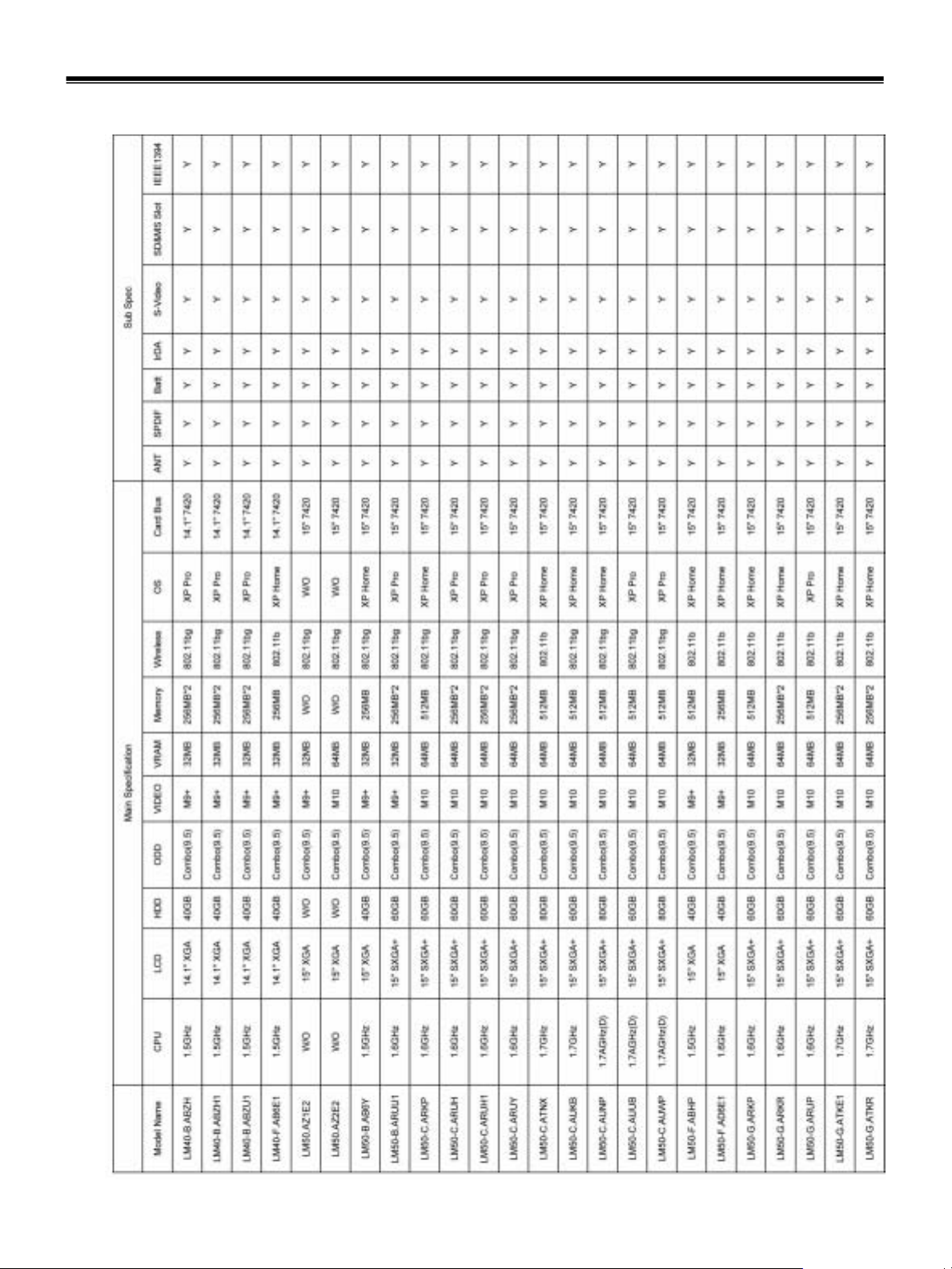
Model Configuration
Ch3. System information
15
Page 17
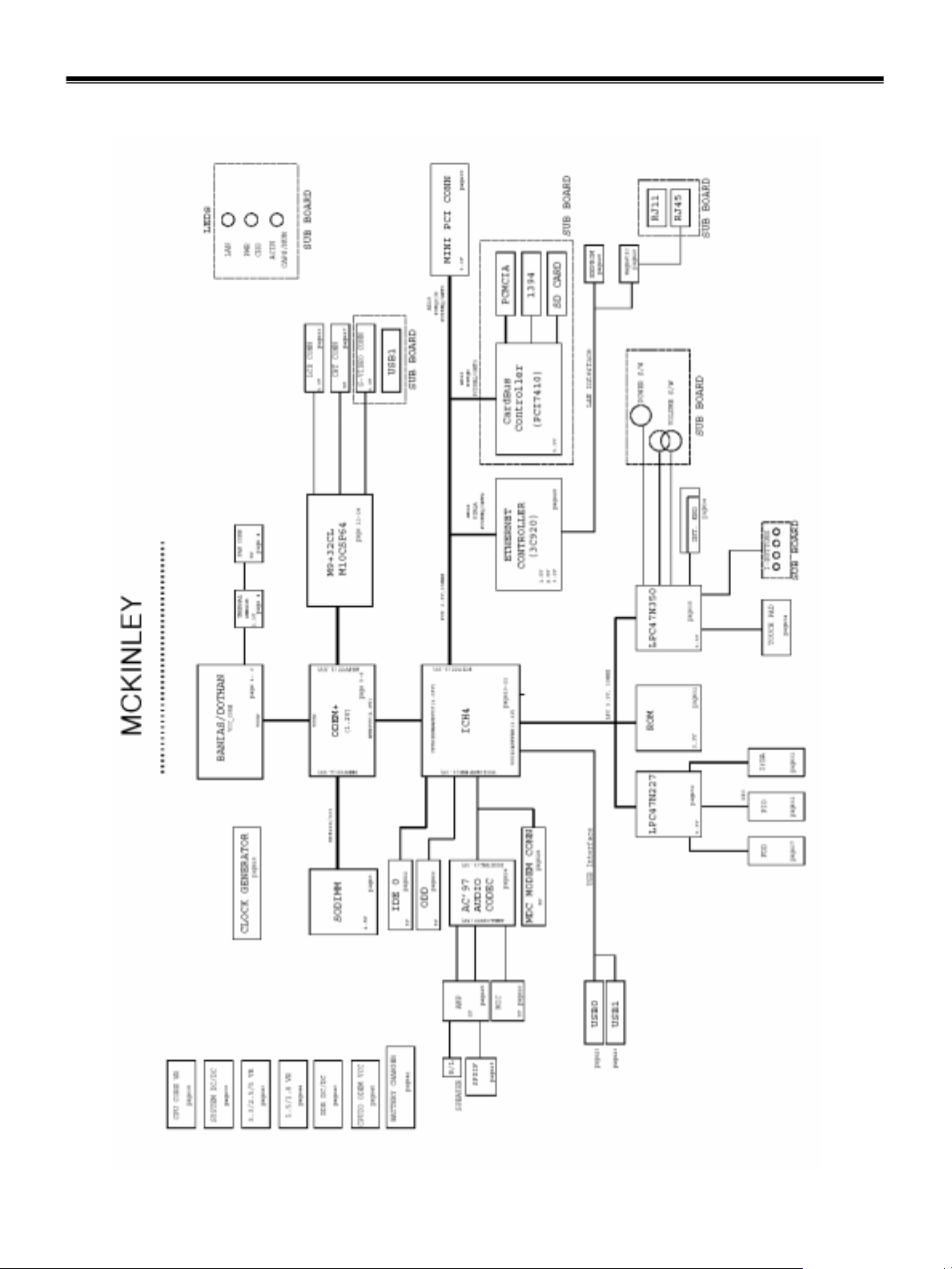
System Block Diagram
Ch3. System information
16
Page 18
Ch3. System information
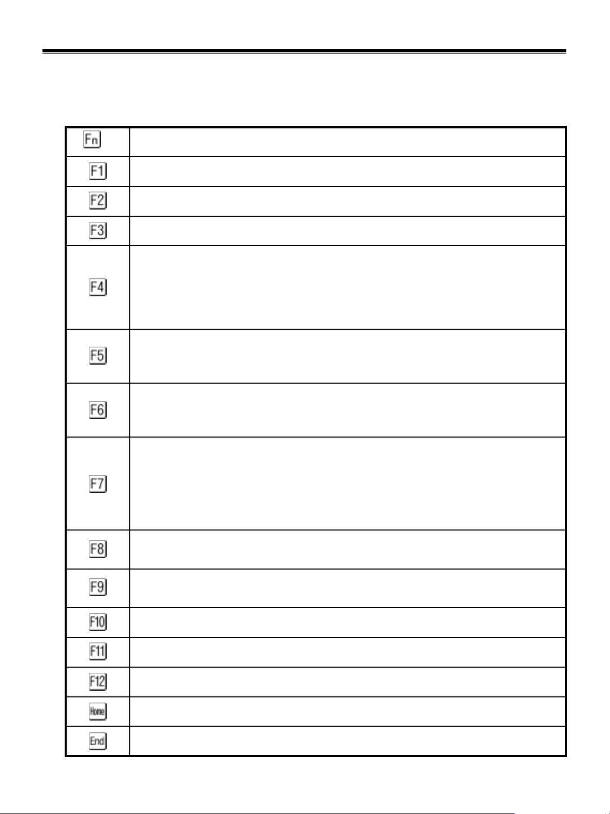
Fn key combinations
The following table shows t he fun ctio n of each com bin ati on of Fn with a functi o n key .
Function of Fn keys has nothing to do with Operating System.
Description+
User-defined Hot key. (Setting is available at O SD)
User-defined Hot key. (Setting is available at O SD)
User-defined Hot key. (Setting is available at O SD)
Put the computer in standby mode.
To turn the LCD display on again, press any key or TouchPad.
(In Windows XP and Windows 2000, this combination of buttons functions as a sleep button.
The setting can be changed so that pressing it puts the computer into hibernation mode or
even shuts the computer down.)
Enable / Disable TouchPad.
Disable TouchPad by pressing once.
Enable TouchPad by pressing once more.
Enable / Disable Wireless LAN.
Disable Wireless LAN by pressing once.
Enable Wireless LAN by pressing once more.
Switch between th e comp u ter di spl ay a n d a n extern al mo nit or. If an external monitor is
attached, computer output is displayed in the following three patterns by turns:
External monitor (CRT display)
Computer display and external monitor (LCD + CRT display)
Computer display (LCD)
Enable / Disable the auto sound control function with the Battery Miser if it is installed.
(To enable this function, you have to install the Battery Miser first.)
Enable Disable the auto brightness control function with the Battery Miser if it is installed.
(To enable this function, you have to install the Battery Miser first.)
User-defined Hot key. (Setting is available at O SD)
User-defined Hot key. (Setting is available at O SD)
User-defined Hot key. (Setting is available at O SD)
The computer display becomes brighter.
The computer display becomes less bright.
17
Page 19
Ch3. System information
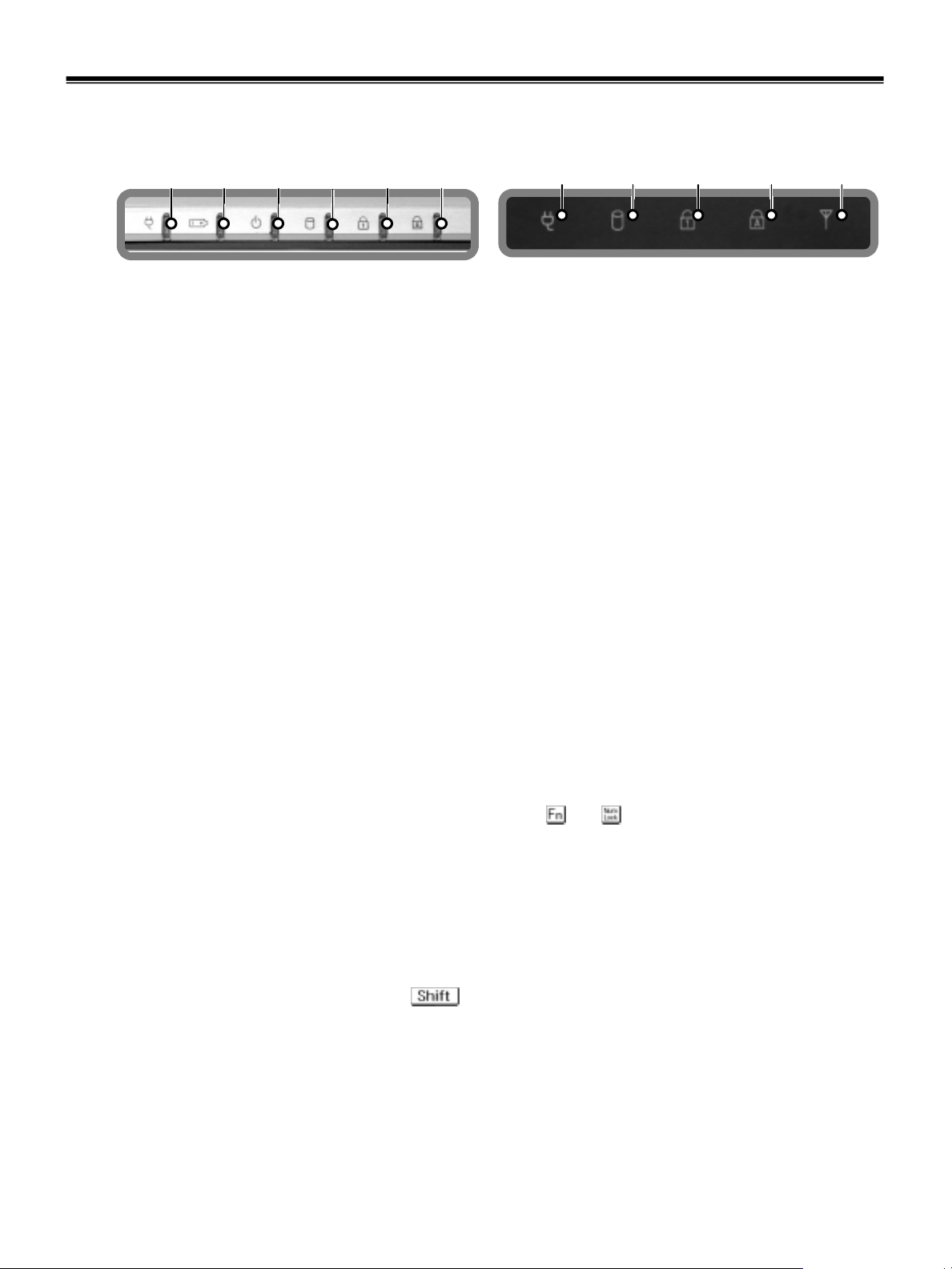
Status indicators
· The system status indicators sho w t h e st at u s of the com p ut er.
a
a. AC Power
Power indicator lights up when the power cord is connected to the computer.
b. Battery
Battery status indicator indicates the following status of the battery.
Green : The computer is connected to an AC adapter and is being charged.
Off : The battery if fully charged OR the computer is not connected to an AC adapter.
Blinking : The battery power is under 10% of its maximum capacity.
b e fc
d
14.1” 15”
a
de f g
c. Power
Power status indicator indicates the following status of the computer.
Green : The computer is turned on.
Off : The computer is turned off or is in hibernation mode.
Blinking : The computer is in standby mode.
d. Drive in use
Drive in use indicator lights up when data is being written to or read from the hard-disk or optical disk
drive.
e. Num Lock
Num Lock indicator lights up when the combination of the and key is pressed.
When this indicator lights up, you can use the embedded numeric keys.
(To use the numeric keys, you must enable the Internal Keypad setting under the Advanced menu in
the BIOS Setup Utility)
f. Caps Lock
Caps lock indicator lights up when the Caps lock key is pressed. When this indicator lights up, you can
type capital letters without pressing the key.
g. Wireless activity indicator
Wireless activity indicator indicates the following.
Blue : The Wireless client is associated with the network.
Off : The Wireless card does not have the power or RF is off.
Blinking : The Wireless client is not associated with the network.
18
Page 20

Ch3. System information
BIOS Flash
You can update BIOS using a floppy disk drive.
Because this system is not equipped with any floppy disk drive, you have to use an external USB drive for
a BIOS update. In order to boot up with an USB drive, please set Removable Device as the first boot up
drive in the boot menu of BIOS setup.
· How to update flash ROM in DOS
1. Create ‘boot up’ flash update diskette.
2. Copy a ROM image file (*.wph) into the root of the flash update diskette.
3. Copy phlash16.exe to the flash update diskette.
4. Insert the diskette into the FDD of your computer.
5. Boot your computer with the diskette, and type ‘phlash16*.wph/mode=n’.
6. Cold boot and follow the instruction displayed on the screen.
· Flash options /mode=n
0 – Default mode. Keep the current DMI information and update BIOS image only.
1 – Update DMI information only.
If new DMI information is not specified, the current DMI information is left unchanged.
2 – Update BIOS and DMI information.
If new DMI information is not specified, the current DMI information is left unchanged.
3 – Update BIOS and DMI information.
DMI information is updated to the DMI string and options specified in the new BIOS image.
Note
DMI is Desktop Management Interface
19
Page 21
Ch3. System information
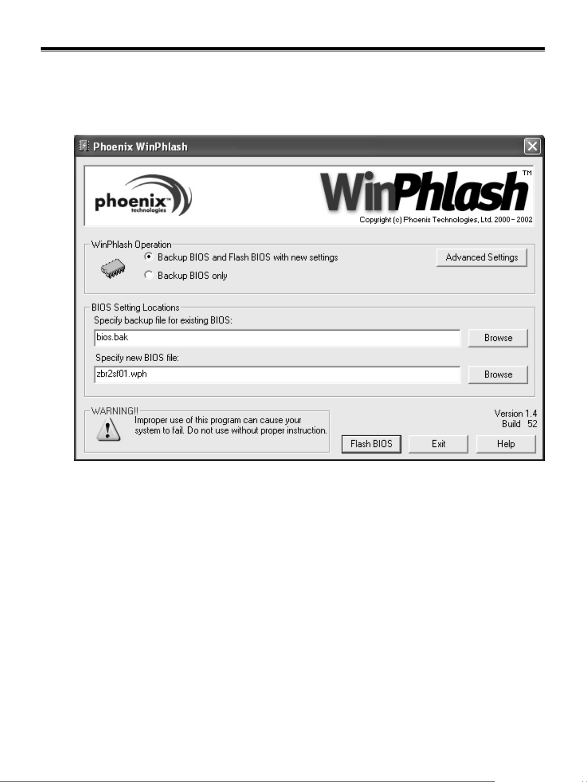
How to update flash ROM in Windows
1. Quit all running programs.
2. Start WINPHLASH.EXE.
3. Select the procedure you want :
a. Backup BIOS and Flash BIOS with new settings
b. Backup BIOS Only
4. Specify the locations for backup and new BIOS files in BIOS Setting Locations.
a. Enter the name of the backup file for existing BIOS or click Browse to locate the file.
b. Enter the name of the new BIOS file or click Browse to locate the file.
5. Click Advanced Settings button to access the advanced settings
6. Click Flash BIOS button to start flash BIOS.
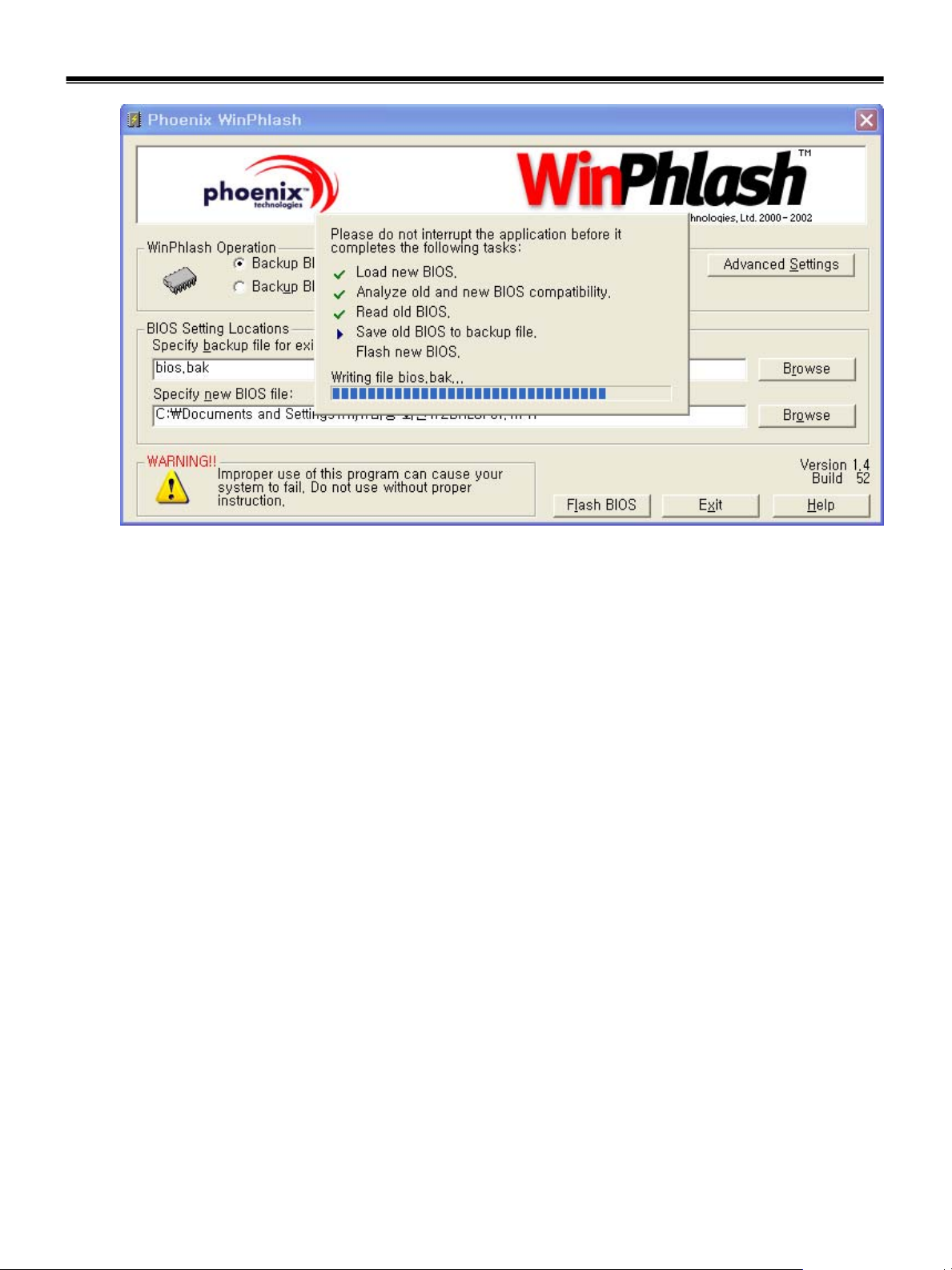
7. Wait for the operation to complete. WinPhlash may take one or two minutes to complete flash BIOS
operation.
20
Page 22
Ch3. System information
8. After the completion, ‘System BIOS was successfully updated’ appears on the screen, then the
computer restarts.
9. After the restart, make sure the system BIOS is updated.
10. If your computer does not restart automatically, turn off your computer and then turn it back on by
pressing power button.
21
Page 23

Ch3. System information
BIOS Setup
BIOS (Basic Input and Output System) Setup saves the sy st em co nfigurat io n in CMOS RAM, and
check the configurations during startup. Use the BIOS Setup Utility to change and save the system
environment, hardware configurations, power saving mode, etc.
· Open the BIOS Setup Utility in the following situations :
1. to change the BIOS setup
2. to replace the backup battery
3. system configuration error occurs
4. to change the boot order
5. to set/change a password
Press the power button.
When the LG logo appears on the screen, press and enter the BIOS Setup Utility.
22
Page 24

Default screen
Ch3. System information
· BIOS Setup Utility menu bar shows the following menus
Main, Advanced, Security, Boot, Exit
· Main menu enables you to set the system time and date, hard disk drive setup, memory configuration, and
floppy disk drive specification.
· Advanced menu enables you to configure the operating environment for peripheral devices, such as
legacy USB, TouchPad, internal keypad, and parallel port.
· Security menu enables you so set or change supervisor and user passwords.
· Boot menu enables you to set the order of drives the system selects to find its operating system during the
boot sequence. Use Enter, + and - keys to change the order.
· Exit menu enables you to save your system configuration.
23
Page 25
Ch3. System information
Using the keys
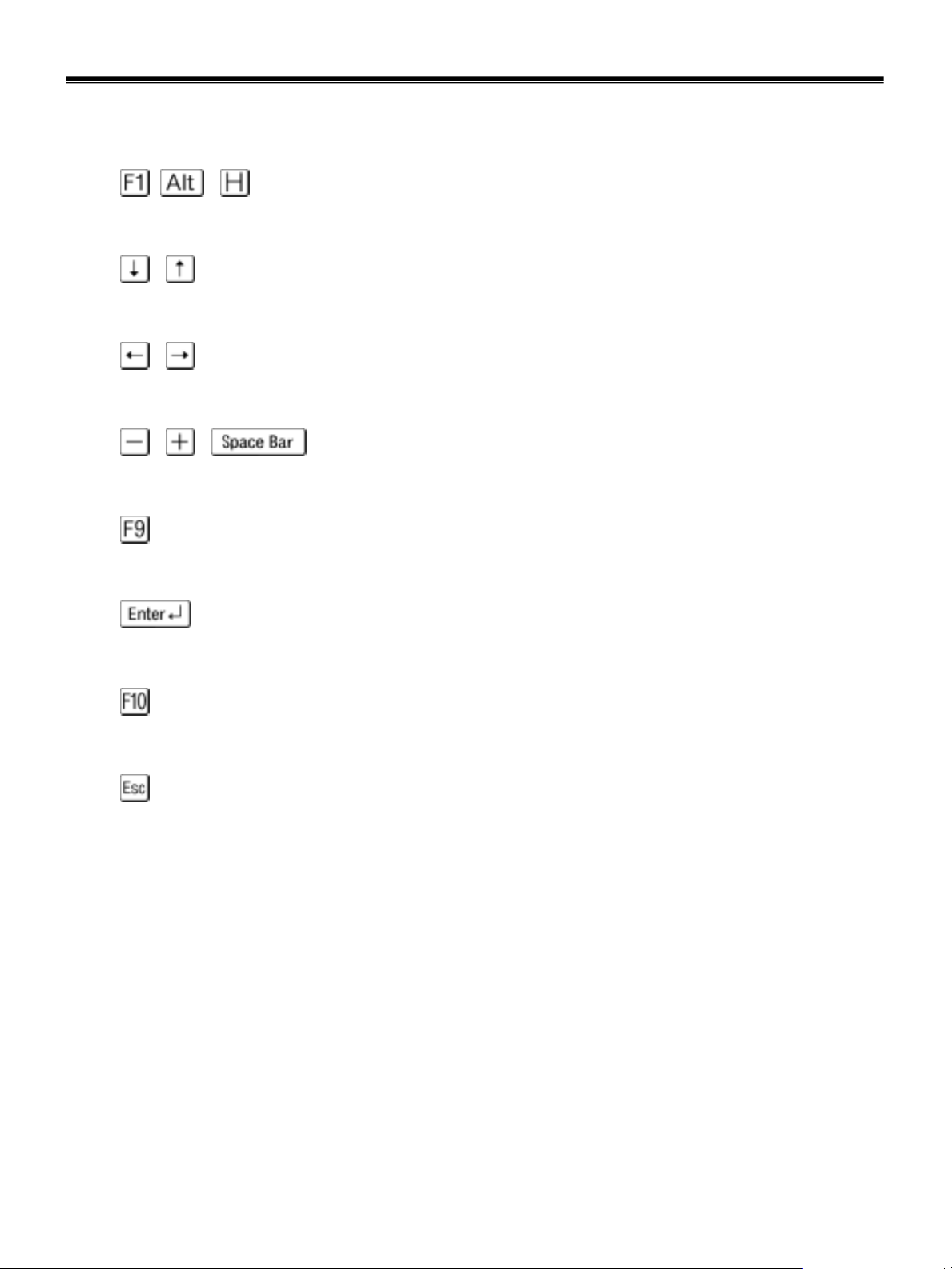
The keys used in the BIOS Setup Utility and their functions are described at the bottom.
· , + : General Help
Display the descriptions of the keys used in the setup utility.
· , : Select Item
Navigate and select items in the setup utility. The selected item becomes highlighted.
· , : Select Menu
Move to another menu.
· / , : Change Values
Change the value of a selected item.
· : Load Default Configuration
Display Setup Confirmation window. Press Enter to load default configuration.
· : Select Sub-Menu
Some items have sub-menus. Display the sub-menu for a selected item.
· : Save and Exit
Display Setup Confirmation window. Press Enter to save and exit.
·: Exit
In a sub-menu, press Esc to move to the previous window. In Main menu, click Esc to move to Exit menu.
24
Page 26
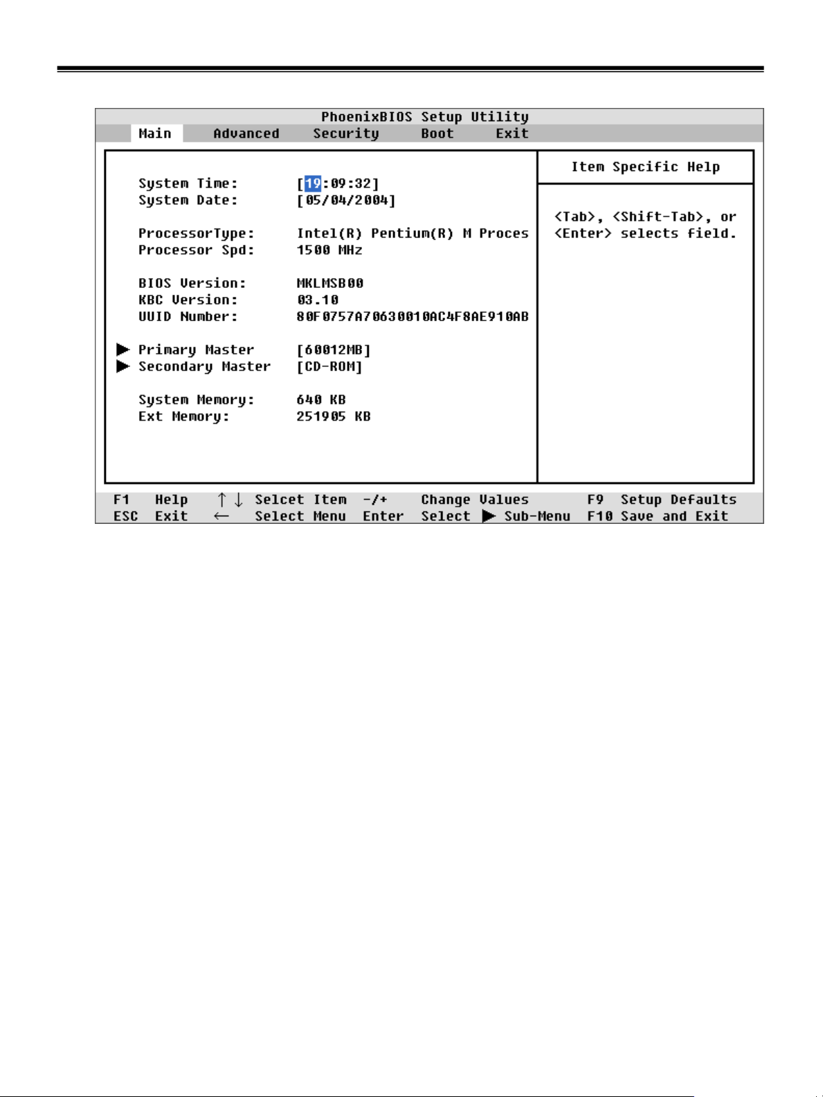
Main Menu
Ch3. System information
· System Time
Set the system time. Use Tab key to move to hour, minute, and second. Use +, -, or Spacebar to change
the values.
· System Date
Set the system date.
· Processor Type / Speed
Indicate CPU type and clock speed installed on the system.
· BIOS Version / KBC Version / UUID Number
Display BIOS / KBC version information and UUID value.
· Primary Master / Secondary Master
Display the information about the device used as the primary master. Press Enter to set the parameters of
the device at this connection.
· System Memory / Extended Memor y
Display the memory size information.
25
Page 27
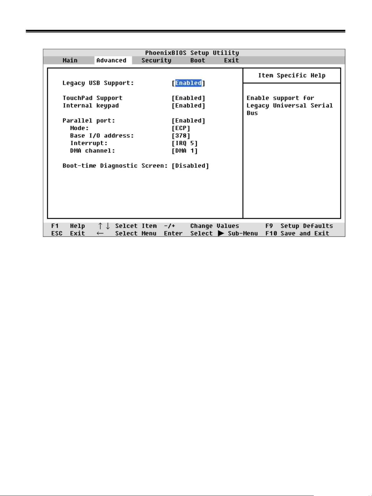
Advanced Menu
Ch3. System information
· Legacy USB Support
Enable support for the Legacy USB. (Enabled / Disabled)
· TouchPad Support
Enable support for TouchPad. (Enabled / Disabled)
· Internal Keypad
Enable support for the internal keypad. (Enabled / Disabled)
26
Page 28

Ch3. System information
· Parallel Port
Configure the parallel port using options. (Enabled / Disabled)
Set the mode for the parallel port using options. (Output only, Bi-directional, EPP, and ECP)
Set the base I/O address for the parallel port. (378 / 278 / 3BC)
Set the interrupt for the parallel port. (IRQ5 / IRQ7)
· Parallel port modes
1. Output only
The normal mode. Use this mode when you connect a printer to the parallel port.
2. Bi-directional
Allows bi-directional high speed data transfer.
3. EPP (Extended Parallel Port)
Allows a connection to a device supporting EPP, EPP uses the existing parallel port signal to allow
asymmetric bi-directional data transfer with a host device.
4. ECP (Extended Capabilities Port)
Allows a connection to a device supporting ECP, ECP increases the data transfer rate and enables you
to set DMA channel. (DMA1 / DMA3)
· Boot-time Diagnostic Screen
Enables the Boot-time Diagnostics Screen (Enabled / Disabled)
27
Page 29
Ch3. System information
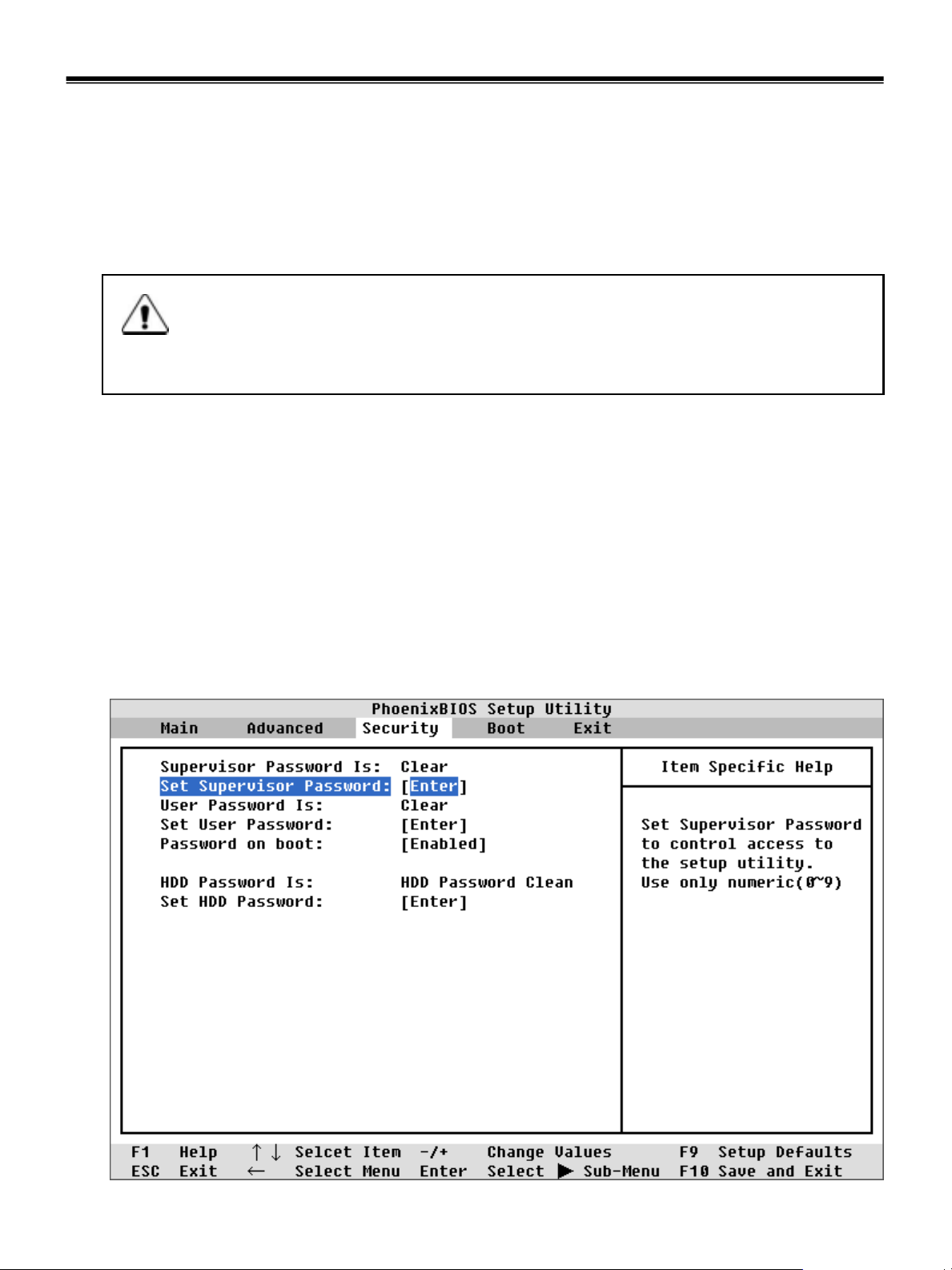
Security Menu
· Setting a password
If you want to protect the system setup from an unauthorized user, follow the instructions below to set a
password.
You can set a password in the BIOS Setup Utility program.
Caution
If you forget the password, you cannot gain access to your system.
Make sure you write down the password in a safe place only you can refer to in case you forget
the password
· Set Supervisor Password
A password protects your computer from unauthorized users. The factory default setup does not have a
password. A supervisor password prevents unauthorized users from changing the system setup.
a. Start the system setup utility and use arrow keys to select Set Supervisor Password under
Security menu, and then press Enter.
b. If the following screen appears, select Set Supervisor Password by using arrow keys, and Enter.
28
Page 30
Ch3. System information
Note
A supervisor password enables you to change settings in the BIOS Setup Utility and to perform
Power on Boot.
Users other than the administrator should only have user passwords.
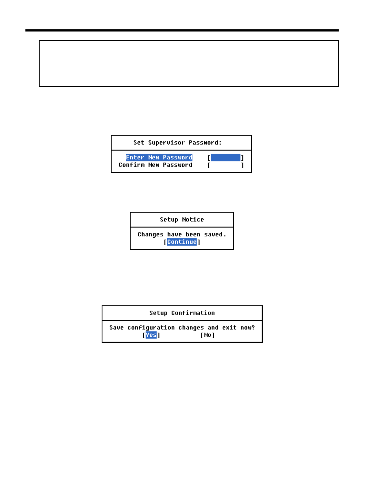
c. If the following message appears, enter a new supervisor password and then Enter.
A password must be consisted of character A~Z and numbers 0~9, and have the maximum
length of 8.
d. If the following message appears, press Enter.
e. Press F10 to save the new settings.
f. If the following message appears, select Yes and press Enter to restart the computer.
29
Page 31

Ch3. System information
· Set User Password
A user password provides a lower level of security compared to a supervisor password.
A supervisor password must be set in order for you to set a user password.
a. Start the BIOS Setup Utility and use arrow keys to select Security menu.
b. Use arrow keys to selected Set User Password and press Enter.
Note
A user password gives limited access for changing the setting in the BIOS Setup Utility compared to
a supervisor password.
c. If the following message appears, enter a new password and press Enter.
A password must be consisted of characters A~Z and numbers 0~9, and have maximum
length of 8.
30
Page 32

Ch3. System information
d. If the following message appears, press Enter.
e. Press F10 to save the new settings.
f. If the following message appears, select Yes and press Enter to restart the computer.
31
Page 33

Ch3. System information
· Password on boot
Enables password entry on boot
a. Start the BIOS Setup Utility and use arrow keys to select Security menu.
b. If the following screen appears, select Set Supervisor Password or Set User Password by using
arrow keys, and input new password.
32
Page 34

Ch3. System information
c. Select Password on boot menu, then change value (Enabled) by using +, - keys.
Note
If you set a Supervisor Password or User Password, you can use Password on boot.
If you set Disabled on Password on boot, You don’t have to enter a password.
33
Page 35

Ch3. System information
· Set HDD Password
Set HDD Password to co n t rol ac ce ss t o th e Har d-d i sk.
Press Enter to input, change or disable hard-disk password.
a. Start the BIOS Setup Utility and use arrow keys to select Security menu.
b. If the following screen appears, select Set HDD Password by using arrow keys, and press Enter.
Note
When loosing your HDD Passw o rd, you can not a cce s s y o ur H ar d-di sk d riv e.
34
Page 36

Ch3. System information
c. If the following message appears, enter a new supervisor password and then press Enter.
A password must be consisted of numbers 0~9, and have the maximum length of 8.
d. If the following message appears, press Enter.
e. Press F10 to save the new settings.
f. If the following message appears, select Yes and press Enter to restart the computer.
35
Page 37

Ch3. System information
· Changing or removing a password
You must know the password in order to change or remove it.
a. Start the BIOS Setup Utility , enter your password, and then press Enter.
b. To change the password, follow the instructions on Set Supervisor Password or
Set User Password.
c. To remove the password, follow the instructions below.
Use arrow keys to select Security menu, and select a password you want to remove, and then press
Enter.
d. If the following message appears, enter the current password in the bracket next to
Enter Current Password, and then press Enter.
Enter
Enter
e. Press Enter without entering a new password in each of the brackets next to Enter N ew Password
and Confirm New Password.
f. If the following message appears, press Enter.
g. Press F10 to save the new setting.
h. If the following message appears, select Yes and press Enter to restart the computer.
36
Page 38

Boot Menu
Ch3. System information
· Boot menu enables you to set the boot order for the CD-ROM drive, Removable devices, Hard drive, and
Network boot.
Boot menu displays the boot order of your system with higher priority given to a device higher on the list.
The default boot order is CD-ROM drive, Removable devices, Hard drive, and Network boot.
Changing the order of the devices on Boot menu changes the boot order of your system.
Use and keys to select a device. Press the combination of Shift and + to move the device up,
and - to move the device down on the list.
· CD-ROM Drive
The CD-ROM drive has the highest priority given in the boot order. Boot your system using the CD-ROM drive
by inserting a bootable CD in the CD-ROM(CD-RW/DVD combo) drive
· Removable Devices
You can set the boot order for more than one removable device, such as a legacy floppy drive.
· Hard Drive
You can set the boot order for more than one hard disk drive.
37
Page 39

Exit Menu
Ch3. System information
· Exit System Setup and save your changes to CMOS.
· Exit Saving Changes
Select Exit Saving Changes to save new setup information in CMOS RAM. CMOS RAM stores the
information using the backup battery; there fore, the information will not be lost when the computer i s
turned off.
· Exit Discarding Changes
Select Exit Discarding Changes to discard new setup information. If you made changes to items other
than date, time, and passwords, the Setup Warning asks you to save the new configurations.
Select Yes and press Enter to save the new configuration.
· Load Setup Defaults
Select Load Setup Defaults to change the setup information to the factory default settings. If you select
Load Setup Defaults or press F9, Setup Confirmation asks you to confirm your selection.
Press Yes to load setup defaults.
38
Page 40

Ch3. System information
· Discard Changes
Select Discard Changes to discard new setup information. Setup Confirmation asks you to confirm
your selection. If you want to discard any new setup information, select Yes.
· Save Changes
Select Save Changes to save any new setup information without exiting the BIOS Setup Utility.
Select Yes to save the new setup information in the Setup Confirmation window.
39
Page 41

Ch4. Symptom-to-part index
Chapter 4. Symptom-to-part index
The symptom-to-part index in this section lists symptoms and errors and their possible causes.
The most likely cause is listed first.
Note
If replacing a part (FRU) does not solve the problem, put the original part back in the computer.
Do not replace a non-defective FRU.
Power system checkout
· To verify a symptom, do the following :
1. Power off the computer.
2. Remove the battery pack.
3. Connect the AC adapter.
4. Check that power is supplied when you power on the computer.
5. Power off the computer.
6. Disconnect the AC adapter and install the charged battery pack.
7. Check that the battery pack supplies power when you power on the computer.
· If you suspect a power problem, see the appropriate one of the following power supply checkouts :
1. Checking the AC adapter
2. Checking the operational charging
3. Checking the battery pack
4. Checking the backup battery
· Checking the AC adapter
If the power-on indicator does not turn on, check the power cord of the AC adapter for correct continuity
and installation.
If the computer does not charge during operation, go to ‘Checking operational charging’.
To check the AC adapter, do the following :
1. Unplug the AC adapter cable from the computer.
2. Measure the output voltage at the plug of the
AC adapter cable. See the following figure :
40
Voltage (V dc)Pin
+18.0 ~ +19.21
2
Ground2
1
Page 42

Ch4. Symptom-to-part index
· If the voltage is not correct, replace the AC adapter.
· If the voltage is acceptable, do the following :
1. Replace the system board.
2. If the problem persists, check the AC adapter whether it is correct product or not.
Note
Noise from the AC adapter does not always indicate a defect.
· Checking operational charging
1. To check whether the battery charges properly during operation, use a discharged battery pack or a
battery pack that has less than 50% of the total power remaining when installed in the computer.
Perform operational charging. If the battery status indicator or icon does not turn on, remove the battery
does not turn on, replace the battery pack.
2. If the charge indicator still does not turn on, replace thesyst em board.
Then reinstall the battery pack.
Note
Do not charge battery pack, when its temperature is below 0 or above 60 .
· Checking the battery pack
1. Open the Power Meter window by clicking Start Control Panel Power Options and then;
check the total power remains. Battery charging does not start until the power Meter shows that less
than 95% of the total power remains; under this condition the battery pack can charge to 100% of its
capacity. This protects the battery pack from being overcharged or from having a shortened life.
2. To check the status of your batter, move your cursor to the Power Meter icon in the icon tray of the
Windows taskbar and wait for a moment (but do not click), and the percentage of battery power
remaining is displayed. To get detailed information about the battery, double-click the Power Meter icon.
Note
If the battery pack becomes hot, it may not be able to charge. Remove it from the computer and
Leave it at room temperature for a while. After it cools down, reinstall and recharge it.
41
Page 43

Ch4. Symptom-to-part index
· The Characteristics of the battery pack
1. Self-discharge
The battery gradually loses its power over time without ever being used.
2. Periodic full discharge / charge
Frequent recharge of the battery pack can reduce the capacity of the battery pack. When this happens,
you can perform the full discharge / charge to improve the capacity. You should perform periodic full
discharge /charge once every 30~60 days.
You should always use the battery until its power is low; then fully charge the battery.
3. Trickle charge
If the temperature of the battery pack drops below 10 , the trickle charging begins.
The trickle charging may take 32 hours for the battery pack to be fully charged.
42
Page 44

Ch4. Symptom-to-part index
· To check the battery pack, do the following :
1. Power off the computer.
2. Remove the battery pack and measure the voltage between batt ery terminals 1(-) and 5(+).
See the following figure :
Voltage (V dc)Terminal
Ground(-)1
5
5(+)
3. If the voltage is still less than +11.1 V DC after recharging, replace the battery.
4. If the voltage is more than +11.1 V DC, measure the resistance between battery terminals 1 and 2.
The resistance must be 2 to 4 (typically 3 ).
5. If the resistance is not correct, replace the battery pack. If the resistance is correct, replace the system
board.
Note
Charging will take at least 3 hours.
Note
Battery is an expendable supplier, so its capacity and used time can be reduced by using the computer.
· Checking the backup battery
1. Remove the backup battery.
2. Measure the voltage of the backup battery. See the following figure.
4 3 2 1(-)
+0V ~ +12.6V
(6 cell / 9-cell)
White (+)
Blue (+)
If the voltage is correct, replace the system board.
If the voltage is not correct, replace the backup battery.
If the backup battery discharges quickly after replacement, replace the system board.
Voltage (V dc)Wire
+2.5 ~ +3.2White
GroundBlue
43
Page 45

Numeric error codes
Ch4. Symptom-to-part index
FRU or action, in sequenceSymptom / Error
0200
Fixed disk failure
(The hard disk is not working)
0210
Stuck Key error
0211
Keyboard error
Keyboard Controller Failed
Monitor type error - Monitor type does not
match the one specified in CMOS.
1.Reset the hard-disk drive.
2.Load Setup Defaults in BIOS Setu p Utility.
3.Hard-disk drive.
4.System board.
1.Check the keyboard if it is pressed.
2.Replace the keyboard.
Run interactive tests of the keyboard a n d th e auxiliary
input device.
System board.0212
Load Setup Defaults in BIOS Setup Utility.0220
0230
System RAM error - System RAM Failed at
offset.
Shadow RAM error - Shadow RAM failed at
offset
0232
Extended RAM error - Extended RAM Failed
at address line
0250
System battery error - System battery is dead
1.DIMM
2.System board
System board0231
1. DIMM
2. System board
Replace the backup battery and run BIOS Setup Utility
to reset the time and date.
44
Page 46

Ch4. Symptom-to-part index
FRU or action, in sequenceSymptom / Error
0251
System CMOS checksum bad
- System CMOS checksum is not correct.
- Default configuration used.
Password checksum bad - The password is
cleared.
0260
System timer error
Check date and time settings - Date and time
error.
0280
Previous boot incomplete
- Default configuration used
from EISA CMOS
Diskette drive A error
Replace the backup battery and run BIOS Setup Utility
to reset the time and date.
Reset the password by running BIOS Setup Utility.0252
1. Replace the backup battery and run BIOS
Setup Utility to reset the time and date.
2. System board.
Run BIOS Setup Utility to reset the time and date.0271
1. Load ‘Setup Default’ in BIOS Setup Utility.
2. DIMM.
3. System board.
Load Setup Defaults in BIOS Setup Utility.0281: Memory Size found by POST differed
Set up the diskette type in BIOS Setup Utility.02B0
Diskette drive B error
02B2
Incorrect drive A type - Floppy diskette drive
error
02B3
Incorrect Drive B type
02D0
System cache error - Cache disabled
(RAM cache failed and BIOS disabled)
02F4
EISA CMOS not writable
02F5
DMA test failed
02F6
Software NMI failed
Set up the diskette type in BIOS Setup Utility.02B1
1. Floppy diskette drive.
2. External FDD cable.
3. I/O card.
1. Floppy diskette drive.
2. External FDD cable.
3. I/O card.
1. Load ‘Setup Default’ in BIOS Setup Utility.
2. System board.
1. Load ‘Setup Default’ in BIOS Setup Utility.
2. Replace the backup battery.
3. System board.
1. DIMM
2. System board
1. DIMM
2. System board
45
Page 47

Ch4. Symptom-to-part index
FRU or action, in sequenceSymptom / Error
02F7
Fail - Safe timer NMI failed
0611
IDE configuration changed
0612
IDE configuration error
0613
Com A configuration changed
0614
Com A configuration error
0615
Com B configuration changed
1. DIMM
2. System board
1. Load Setup Defaults in BIOS Setup Utility.
2. System board.
1. Load Setup Defaults in BIOS Setup Utility.
2. System board.
1. Load Setup Defaults in BIOS Setup Utility.
2. System board.
1. Load Setup Defaults in BIOS Setup Utility.
2. System board.
1. Load Setup Defaults in BIOS Setup Utility.
2. System board.
0616
Com B configuration error
0617
Floppy configuration changed
0618
Floppy configuration error
0619
Parallel port configuration changed
061A
Parallel port configuration error
1. Load Setup Defaults in BIOS Setup Utility.
2. System board.
1. Load Setup Defaults in BIOS Setup Utility.
2. System board.
1. Load Setup Defaults in BIOS Setup Utility.
2. System board.
1. Load Setup Defaults in BIOS Setup Utility.
2. System board.
1. Load Setup Defaults in BIOS Setup Utility.
2. System board.
46
Page 48

Error message
Ch4. Symptom-to-part index
FRU or action, in sequenceSymptom / Error
Device address conflict.
Allocation error for device.
Failing bits: nnnn.
Invalid System Configuration Data.
I/O Device IRQ Conflict.
1. Load Setup Defaults in BIOS Setup Utility.
2. Backup battery.
3. System board.
1. Load Setup Defaults in BIOS Setup Utility.
2. Backup battery.
3. System board.
1. DIMM.
2. System board.
1. DIMM.
2. System board.
1. Load Setup Defaults in BIOS Setup Utility.
2. Backup battery.
3. System board.
Operating System no t foun d.
Hibernation error.
1. Check that the operating system has no failure and
is installed correctly.
2. Enter BIOS Setup Utility and see whether the hard
-disk drive and the diskette drive are properly
identified.
3. Reset the hard-disk drive.
4. Reinstall the operating system.
5. Diskette drive.
6. Hard-disk drive.
7. System board.
1. Restore the system configurati o n to what it was
before the computer entered hibernation mode.
2. If memory size has been changed, re-create the
hibernation file.
Fan.FAN error.
47
System board.Thermal sensing error.
Page 49

Ch4. Symptom-to-part index
LCD-related symptoms
Note
Before removing or disassembling LCD, power off the computer, unplug all power cords from electrical
outlets, remove the battery pack also.
FRU or action, in sequenceSymptom / Error
Check out Battery Miser.LCD screen becomes dark suddenly.
Nothing displayed on LCD screen.
LCD backlight not working.
LCD too dark.
LCD brightness cannot be adjusted.
LCD color cannot be adjusted.
LCD screen abnormal.
Characters missing pixels.
LCD screen unreadable.
Wrong color displayed.
1. Check out Battery Miser.
2. Choose Never in the Turn off Monitor item on
Power Options Properties.
3. Check the power save mode switch if it is pressed
by something.
4. Check the System is in standby or hibernation
mode.
1. Reconnect inverter to the board connector.
2. Replace inverter.
3. LCD assembly.
4. System board.
1. Reset all LCD connectors.
2. Replace LCD cable.
3. LCD assembly.
4. System board.
on LCD
Power-on indicator on, and a blank LCD
during POST.
LCD assembly.Horizontal or vertical lines display ed
LCD assembly.
System board.
48
Page 50

Ch4. Symptom-to-part index
Indeterminate problems
· You are here because the diagnostic tests did not identify which adapter or device failed, wrong devices
are installed, a short circuit is suspected, or the system is inoperative.
Follow these procedures to isolate the failing FRU (do not isolate FRUs that have no defects).
· Verify that all attached devices are supported by the computer.
· Verify that the power supply being used at the time of the failure is operating correctly.
1. Power off the computer
2. Visually check each FRU for damage. Replace any damaged FRU.
3. Remove or disconnected all of the following devices :
a. Non-LG devices.
b. Printer, mouse, and other external devices.
c. Battery pa ck.
d. PC cards.
e. ODD (CD-ROM, Combo) drive or FDD drive in the Bay.
f. Hard-disk drive.
Note
Use the other memory card because it needs when operating computer.
4. Power on the computer.
5. Determine whether the problem has changed.
6. If the problem does not recur, reconnect the removed devices one at a time until you find the failing FRU.
7. If the problem remains, replace the following FRUs one at a time.
(do not replace a non-defective FRU)
a. LCD assembly (Check external monitor whether the same problem recurs or not).
b. Keyboard.
c. Keydeck (TouchPad and Scroll Button assembly).
d. System board.
49
Page 51

Ch5. Removing and replacing a part
Chapter 5. Removing and replacing a part (FRU)
Danger
Before removing any FRU, power off the comput er, u npl u g all power cords from electrical
outlets, remove the battery pack, and then disconnect any interconnecting cables.
Caution
Before the computer is powered on after FRU replacement, make sure that all screws, springs,
and other small parts are in place and are not loose inside the computer. Verify metal flakes can
cause electrical short circuits.
Note
As for the screw, every Torque 2 0.2Kgfcm(0.196Nm)
50
Page 52

Ch5. Removing and replacing a part
1010 Battery Pack
1. Push the battery latch in the direction shown below, then slide the battery pack out of the slot.
51
Page 53

Ch5. Removing and replacing a part
1020 Hard Disk Drive
Remove the following parts in order before replacing this part.
a. Battery Pack(1010)
1. Remove a screw as indicated in the picture, then pull the HDD assembly out in the direction shown below.
1
QtySpecificationFRU No.No.
1M3.0 X L5.01SZZBA4011E1
52
Page 54

Ch5. Removing and replacing a part
1030 Retainer
Remove the following parts in order before replacing this part.
a. Battery Pack(1010)
1. Remove 2 screws.
1
1
QtySpecificationFRU No.No.
2M2.0 X L8.01SZZBA4083A1
53
Page 55

Ch5. Removing and replacing a part
2. To remove three hooks, insert a (-) type screwdriver into a hook located at the lo wer end of keyboard,
and pull it up.
54
Page 56

Ch5. Removing and replacing a part
3. Disconnect the keyboard connector.
55
Page 57

Ch5. Removing and replacing a part
1040 Retainer
Remove the following parts in order before replacing this part.
a. Battery Pack(1010) b. Keyboard(1030)
1. Pull up the retainer, and remove the connector usi ng a (-) type screwdriver.
56
Page 58

Ch5. Removing and replacing a part
1050 Fan Assembly
Remove the following parts in order before replacing this part.
a. Battery Pack(1010) b. Keyboard(1030) c. Retainer(1040)
1. After removing a screw and the connector, pull up and remove the fan assembly using a (-) type
screwdriver.
1
1
1
QtySpecificationFRU No.No.
3M2.0 X L8.81SZZBZ4020A1
57
Page 59

Ch5. Removing and replacing a part
58
Page 60

Ch5. Removing and replacing a part
1060-1 Optical Disk Drive (15” Model)
Remove the following parts in order before replacing this part.
a. Battery Pack(1010) b. Keyboard(1030) c. Retainer(1040)
1. Remove a screw, insert a screwdriver into the hole located at the rear of ODD and push it out.
1
59
QtySpecificationFRU No.No.
1M2.0 X L5.01SZZBZ4014A1
Page 61

Ch5. Removing and replacing a part
1060-2 Optical Disk Drive (14.1” Model)
Remove the following parts in order before replacing this part.
a. Battery Pack(1010) b. Keyboard(1030) c. Retainer(1040)
1. Remove a screw, insert a screwdriver into the back side of ODD and push it out.
1
60
QtySpecificationFRU No.No.
1M2.0 X L5.01SZZBZ4014A1
Page 62

Ch5. Removing and replacing a part
1070 Wireless LAN Card
Remove the following parts in order before replacing this part.
a. Battery Pack(1010) b. Keyboard(1030) c. Retainer(1040)
1. Remove two wireless LAN card connector, open card knob to take out the card.
61
Page 63

Ch5. Removing and replacing a part
1080 MDC Modem Card
Remove the following parts in order before replacing this part.
a. Battery Pack(1010) b. Keyboard(1030) c. Retainer(1040)
1. Remove two screws and insert a screwdriver below the modem. Pull it up to disassemble.
1
1
62
QtySpecificationFRU No.No.
2M2.0 X L3.51SZZBA4017B1
Page 64

Ch5. Removing and replacing a part
1090 Display Module
Remove the following parts in order before replacing this part.
a. Battery Pack(1010) b. Keyboard(1030) c. Retainer(1040) d. Wireless LAN Card(1070)
1. Remove two screws.
1
1
QtySpecificationFRU No.No.
2M2.5 X L8.01SZZBA4039B1
63
Page 65

Ch5. Removing and replacing a part
2. Remove two hinge cover screws.
1
1
QtySpecificationFRU No.No.
2M2.0 X L5.01SZZBZ4014A1
64
Page 66

Ch5. Removing and replacing a part
3. Using a (-) type screwdriver from the back of LCD, pull up the hinge cover with your finger. Then more
you move the LCD to the back, the easier the hinge cover will pull out. Remove another hinge cover
located on the other side.
4. Remove two hinge screws.
1
1
QtySpecificationFRU No.No.
65
2M2.5 X L8.01SZZBA4039B1
Page 67

Ch5. Removing and replacing a part
5. Remove the LCD connector located at the upper end of MCD modem. You will see a tag designed to
make work easier. Pull out the tag.
4. Remove the LCD cable.
66
Page 68

Ch5. Removing and replacing a part
7. Hold the LCD with your both hands, and pull it up to remove.
Note
Display Module disassembly in detail (1140)
67
Page 69

Ch5. Removing and replacing a part
1100 Keyboard Deck
Remove the following parts in order before replacing this part.
a. Battery Pack(1010) b. Keyboard(1030) c. Retainer(1040) d. Fan Assembly(1050)
e. Wireless LAN Card (1070) f. MDC Modem Card(1080) g. Display Module(1090)
1. Remove 14 screws (for 15” model) or 11 screws (for 14.1” model).
The screw type is shown on the set for your reference.
15”
1
1
Screw Type
1
1
1
1
2
1
1
1
1
1
11
QtySpecificationFRU No.No.
13M2.0 X L8.01SZZBA4083A1
1M2.0 X L13.01SZZBA4067A2
68
Page 70

14.1”
Ch5. Removing and replacing a part
1
1
1
1
Screw Type
1
1
1
1
Screw Type
1
1
1
2
2
1
1
1
1
1
1
1
1
1
11
1
QtySpecificationFRU No.No.
10M2.0 X L8.01SZZBA4083A1
1M2.0 X L13.01SZZBA4067A2
69
Page 71

Ch5. Removing and replacing a part
2. Open the I/O port cover and remove two screws.
1
1
QtySpecificationFRU No.No.
2M2.0 X L3.51SZZBA4017B1
70
Page 72

3. Remove 3 screws.
Ch5. Removing and replacing a part
1
1
1
QtySpecificationFRU No.No.
3M2.0 X L2.01SZZBZ4018B1
71
Page 73

Ch5. Removing and replacing a part
4. Remove the cable, hold the keyboard deck with your both hands and pull it out.
72
Page 74

Ch5. Removing and replacing a part
5. Remove the speaker cable located at the front of key deck that is pulled up.
73
Page 75

Ch5. Removing and replacing a part
1110 Main Board
Remove the following parts in order before replacing this part.
a. Battery Pack(1010) b. Keyboard(1030) c. Retainer(1040) d. Fan Assembly(1050)
e. Wireless LAN Card (1070) f. MDC Modem Card(1080) g. Display Module(1090)
h. Keyboard Deck(1100)
1. Remove two screws and disassemble the ODD Plate Assembly.
1
1
QtySpecificationFRU No.No.
2M2.0 X L2.51SZZBZ3009B1 (14.1”)
2M2.0 X L5.01SZZBZ4014A1 (15”)
74
Page 76

Ch5. Removing and replacing a part
2. Remove the PCMCIA board.
3. Remove the RTC battery connector from Main Board.
75
Page 77

Ch5. Removing and replacing a part
4. Remove the S-Video connector.
5. Remove the LAN S/B connector.
76
Page 78

6. Remove the power cable.
Ch5. Removing and replacing a part
7. Remove 4M/B screws.
2
1
1
1
QtySpecificationFRU No.No.
77
3M2.0 X L5.01SZZBA4014A1
1M2.0 X L3.51SZZBA4017B2
Page 79

Ch5. Removing and replacing a part
8. Hold M/B with your both hand and pull it up to remove.
78
Page 80

Ch5. Removing and replacing a part
1120 Battery Frame Assembly
Remove the following parts in order before replacing this part.
a. Battery Pack(1010) b. Keyboard(1030) c. Retainer(1040) d. Fan Assembly(1050)
e. Wireless LAN Card (1070) f. MDC Modem Card(1080) g. Display Module(1090)
h. Keyboard Deck(1100) i. Main Board(1110)
1. Remove a screw.
1
QtySpecificationFRU No.No.
1M2.0 X L3.51SZZBA4017B1
79
Page 81

Ch5. Removing and replacing a part
2. Pull up the battery frame finger plate, and remove the battery frame assembly. The LAN S/B will be
removed as well when the battery frame assembly is disassembled.
80
Page 82

Ch5. Removing and replacing a part
1130 S-Video Sub-Board
Remove the following parts in order before replacing this part.
a. Battery Pack(1010) b. Keyboard(1030) c. Retainer(1040) d. Fan Assembly(1050)
e. Wireless LAN Card (1070) f. MDC Modem Card(1080) g. Display Module(1090)
h. Keyboard Deck(1100) i. Main Board(1110)
1. Remove the S-Video sub-board.
81
Page 83

Ch5. Removing and replacing a part
1140 Display Module
Remove the following parts in order before replacing this part.
a. Battery Pack(1010) b. Keyboard(1030) c. Retainer(1040) d. Fan Assembly(1050)
e. Wireless LAN Card (1070)
1. Using a knife, remove the logo and rubbers that are covering the screws. Then remove all 7 screws.
1
1
1
1
2 2
1
QtySpecificationFRU No.No.
5M2.5 X L4.01SZZBA4044B1
2M2.5 XL5.01SZZBA4068A2
82
Page 84

Ch5. Removing and replacing a part
2. Disassemble the LCD front. The front hook located on the middle of LCD upper and lower end.
Be careful of the direction when removing because it is connected from inside out.
83
Page 85

Ch5. Removing and replacing a part
3. Remove cable connector. Remove the cable that is arranged around LCD from LCD frame.
84
Page 86

Ch5. Removing and replacing a part
4. Remove 9 screws (for 15” model) or 8 screws (for 14.1”).
232
3
(15”)
1
1
1 1
(15”)
22
QtySpecificationFRU No.No.
4M2.0 X L2.51SZZBZ3009B1
4M2.5 XL4.01SZZBA4044B2
1M2.0 X L3.01SZZBA4041A
85
Page 87

Ch5. Removing and replacing a part
5. Press the hook on the both side of LCD with a (-) type screwdriver and remove from the LCD real panel.
86
Page 88

Ch5. Removing and replacing a part
6. Remove LCD from the LCD rear panel.
87
Page 89

Ch6. Part lists
Chapter 6. Part lists
TFT LCD, LG PHILIPS LP150E06-A2 15.0 INCH SXGA+6304FLP081AMKL02
TFT LCD, LG PHILIPS LP 1 5 0X08-A3M 1 1 5 . 0 IN CH XGA6304FLP080AMKL02
TFT LCD, AU B150XG01 15.0 INCH XGA6304FAU002BMKL02
TFT LCD, BOE-HYDIS HT15X34-100 15 . 0 INCH XGA6304FBH005AMKL02
CASE ASSY, FRONT 15.0"3111BZ7101AMKL03
KNOB, LATCH4940BM4146AMKL04
LATCH, DISPLAY4026BM3013AMKL05
SPRING, LCD LATCH4970BW4540AMKL06
CUSHION, RUBBER UPPER4850BM4010AMKL07
CUSHION, RUBBER LOWER4850BM4011AMKL08
HINGE ASSY, LEFT 15.0"4775B00033AMKL09
HINGE ASSY, RIGHT 15.0"4775B00034AMKL10
CABLE ASSY, LCD 15.0"6851B76028AMKL11
CABLE FPC, WIRELESS INDICATOR 15.1"6871BZT17AAMKL12
2004. 4. 28. MKB21
REMARKSSPECIFICATIONLG P/NLocation
INVERTER, ALPS KUBNKM063A6708BI0082AMKL13
INVERTER, DELTA DAC-08B043A6708BI0083AMKL13
REAR CASE, 15.0" FOR EXPORT3110BD0009BMKL14
MCKINLEY MG DISPLAY REAR 15.0" FOR MC REFRESH3110BD0009DMKL14
INSULATOR, INVERTER 14.1"/15.0"3858BZ3019AMKL15
ANTENNA, WIRELESS RIGHT3301BZ0512BMKL16
DECORATION COVER, 15.0" FOR EXPORT3550BM2093BMKL17
ANTENNA, WIRELESS LEFT3301BZ0513BMKL18
TFT LCD, BOE HYDIS HT14X1B-110 1 4. 1 INCH XGA6304FBH004AMKL20
TFT LCD, LG PHILIPS LP 1 4 1X13-C2 1 4. 1 INCH XGA6304FLP079AMKL20
LP141X13-C2K1 LG PHILPS TFT COLOR 14.1 INCH XGA(1024X768) ISP ST YL E B6304FLP079BMKL20
CASE ASSY, FRONT 14.1"3111BZ7100AMKL21
LENS, WIRELESS REAR 14.1"3680BM3036AMKL22
DECORATION COVER, 14.1" FOR EXPORT3550BM1149BMKL23
HINGE ASSY, LEFT 14.1"4775BZ1004AMKL24
For refresh
model
HINGE ASSY, RIGHT 14.1"4775BZ1005AMKL25
CABLE ASSY, LCD 14.1"6851B76024AMKL26
INSULATOR, LED 14.1"3858BZ3020AMKL27
REAR CASE, 14.1" FOR EXPORT3110BD0008BMKL28
88
Page 90

Ch6. Part lists
REMARKSSPECIFICATIONLG P/NLocation
For refresh MCKINLEY MG DISPLAY REAR 14.1" FOR MC REFRESH3110BD0008DMKL28
CABLE FPC, WIRELESS INDICATOR 14.1"6871BZT16ZAMKL29
3850BB3035DMKL30
3850BB3035PMKL30
3850BB3035QMKL30
6871BF300A1MKB01
MODEL NAME LABEL, MCKINLEY 14.1" FOR EXPORT
MODEL NAME LABEL, MCKINLEY 15.0" FOR EXPORT3850BB3035EMKL30
MCKINLEY N N MODEL NAME LABEL 14.1" MCKINLEY LM40A FOR REFRESH
EXPORT
MCKINLEY N N MODEL NAME LABEL 15" MCKINLEY LM50A FOR REFRESH
EXPORT
MCKINLEY N N N MCKINLEY BADGE FOR EXPORT LG3858BZ4450BMKL31
MAINBOARD ASSY, BH M9+ P.P LGE 8 LAYERS REV 0.5 6871BF100A1MKB01
MAINBOARD ASSY, BH M10 P.P LGE 8 LAYERS REV 0.56871BF200A1MKB01
MCKINLEY US007506 REFRESH MODEL . LGE 8 LAYERS REV 0.7 M11
MAINSTEAM MAIN ASSY
MEMORY, SAMSUNG M470L3224FT0-CB3 SODIMM 256MB DDR 333MHZ 0IMMRSS090AMKC01
MEMORY, HYNIX HYMD232M646C6-J SODIMM 256MB DDR 333MHZ 0IMMRHY044AMKC01
MEMORY, INFINEON HYS64D32020GDL-6-B SODIMM 256MB DDR 333MHZ0IMMRIH032AMKC01
MEMORY, SAMSUNG M470L6423EN0-CB3 SODIMM 512MB DDR 333MHZ0IMMRSS091AMKC01
For refresh
model
For refresh
model
For refresh
model
For refresh
model
MEMORY, INFINEON HYS64D64020GBDL-6-B SODIMM 512MB DDR 333MHZ0IMMRIH033AMKC01
DVD/CDRW COMBO, TOSHIBA SD-R9012 8X 16X 8X 24X BUILT IN 9.5 MM 2029BG0100AMKC02
DVD, TEAC DV-28E-BC-43 8X 24X BUILT IN 9.5 MM 6777BG0001AMKC02
WIRELESS LAN, INTEL WM3B2100W W MINI-PCI TYPE IIIB6871BZT13A4MKC04
6871BZT14A4MKC04
6871BZT13A5MKC04
MCKINLEY N WM3B2200BGRW PRO/WIRELESS2200BG LAN MINI-PCI TYPE INTEL
4 LAYERS 1-14 NETWORK CONNECTION
WM3B2100NA1 MINI-PCI TYPE IIIB INTEL 4 LAYERS 1-11 PRO/WIRELESS2100
LAN MINI-PCI TYPE 3B ADAPTER LIO
MDC MODEM, AMBIT T60M283.13 56K6871BG105AAMKC05
LI-ION BATTERY, SIMPLO 4400MAH 3S-2P 6911BZ0045BMKC06
LI-ION BATTERY, SIMPLO 6600MAH 3S-3P 6911BZ0046BMKC06
FAN ASSY, W/ SHEET5901B09265AMKC07
MCKINLEY LG-IBM SUNREX-K021102A US-ENG 14.1" 84 KEY3823B70004AMKC08
MCKINLEY LG-IBM SUNREX US-ENG LM REFRESH 14"3823B71004AMKC08
For refresh
model
USA,Canada,
Taiwan
For refresh
model
89
Page 91

Ch6. Part lists
REMARKSSPECIFICATIONLG P/NLocation
MCKINLEY LG-IBM SUNREX-K021102A RUSSIAN 14.1" 84 KEY3823B70004CMKC08
MCKINLEY LG-IBM SUNREX RUSSIAN LM REFRESH 14"3823B71004CMKC08
MCKINLEY LG-IBM SUNREX K021167 ARABIAN 14.1" 84 KEY3823B70004DMKC08
MCKINLEY LG-IBM SUNREX ARAB LM EFRESH 14"3823B71004DMKC08
MCKINLEY LG-IBM SUNREX K021167 HEBREW 14.1" 84 KEY3823B70004EMKC08
MCKINLEY LG-IBM SUNREX HEBREW LM REFRESH 14"3823B71004EMKC08
MCKINLEY LG-IBM SUNREX K021167 FARSI(IRAN) 14.1" 84 KEY3823B70004FMKC08
MCKINLEY LG-IBM SUNREX FARSI LM REFRESH 14"3823B71004FMKC08
MCKINLEY LG-IBM SUNREX K021167 US SOUTH AFRICA 14.1" 84 KEY3823B70004HMKC08
MCKINLEY LG-IBM SUNREX US SOUTH AFRICA LM REFRESH 14"3823B71004HMKC08
MCKINLEY LG-IBM SUNREX K021167 UKRAINIAN 14.1" 84 KEY3823B70004GMKC08
MCKINLEY N SUNREX UKRAINIAN LM REFRESH 14"3823B71004GMKC08
For refresh
model
For refresh
model
For refresh
model
For refresh
model
For refresh
model
For refresh
model
MCKINLEY LG-IBM SUNREX K021167 SPANISH 14.1" 84KEY3823B70004KMKC08
MCKINLEY LG-IBM SUNREX K021167 PORTUGUESE 14.1" 84 KEY3823B70004JMKC08
MCKINLEY LG-IBM SUNREX K021167 POLISH 14.1" 84KEY3823B70004LMKC08
MCKINLEY LG-IBM SUNREX POLISH LM REFRESH 14"3823B71004LMKC08
MCKINLEY N SUNREX K021167 FRENCH 14.1" 84KEY3823B70004MMKC08
MCKINLEY LG-IBM SUNREX FRENCH REFRESH LM 14"3823B71004MMKC08
MCKINLEY N SUNREX THAILAND 14" 84KEY3823B70004NMKC08
MCKINLEY N SUNREX THAILAND LM REFRESH 14"3823B71004NMKC08
MCKINLEY LG-IBM SUNREX TAIWAN 1 4. 1 " 8 4K EY3823B70004PMKC08
MCKINLEY N SUNREX TAIWAN LM REFRESH 14"3823B71004PMKC08
MCKINLEY N SUNREX HUNGARY REFRESH LM 14"3823B71004QMKC08
For refresh
model
For refresh
model
For refresh
model
For refresh
model
For refresh
model
90
Page 92

Ch6. Part lists
REMARKSSPECIFICATIONLG P/NLocation
MCKINLEY N SUNREX CZECH LM REFRESH 14"3823B71004RMKC08
MCKINLEY N SUNREX TURKEY REFRESH LM 14"3823B71004SMKC08
MCKINLEY LG-IBM OKI US-ENG 15" 86 KEY3823B70008AMKC08
MCKINLEY LG-IBM OKI US LM REFRESH 15"3823B71008AMKC08
MCKINLEY LG-IBM OKI RUSSIAN 15" 86 KEY3823B70008CMKC08
MCKINLEY LG-IBM OKI RUSSIAN LM REFRESH 15"3823B71008CMKC08
MCKINLEY LG-IBM OKI ARABIAN 15" 86 KEY3823B70008DMKC08
MCKINLEY LG-IBM OKI ARAB LM REFRESH 15"3823B71008DMKC08
MCKINLEY LG-IBM SUNREX-K020346A HEBREW 15" 86 KEY3823B70008EMKC08
MCKINLEY LG-IBM OKI HEBREW LM REFRESH 15"3823B71008EMKC08
MCKINLEY LG-IBM OKI FARSI 15" 86 KEY3823B70008FMKC08
For refresh
model
For refresh
model
For refresh
model
For refresh
model
For refresh
model
For refresh
model
MCKINLEY LG-IBM OKI FARSI LM REFRESH 15"3823B71008FMKC08
MCKINLEY LG-IBM OKI US SOUTH AFRICA 15" 86KEY3823B70008HMKC08
MCKINLEY LG-IBM OKI US SOUTH AFRICA LM REFRESH 1 5 "3823B71008HMKC08
MCKINLEY LG-IBM OKI UKRAINAIN 15" 86 KEY3823B70008GMKC08
MCKINLEY N OKI UKRAINAIN LM REFRESH 15"3823B71008GMKC08
MCKINLEY LG-IBM OKI SPANISH 15" 86KEY3823B70008KMKC08
MCKINLEY LG-IBM OKI PORTUGUESE 15" 86KEY3823B70008JMKC08
MCKINLEY LG-IBM OKI POLISH 15" 87KEY3823B70008LMKC08
MCKINLEY LG-IBM OKI POLISH LM REFRESH 15"3823B71008LMKC08
MCKINLEY N OKI FRENCH 15" 87KEY3823B70008MMKC08
MCKINLEY LG-IBM OKI FRENCH REFRESH LM 15"3823B71008MMKC08
For refresh
model
For refresh
model
For refresh
model
For refresh
model
For refresh
model
MCKINLEY LG-IBM SUNREX THAILAND 15" LM 84KEY3823B70008NMKC08
91
Page 93

Ch6. Part lists
REMARKSSPECIFICATIONLG P/NLocation
MCKINLEY N OKI THAILAND LM REFRESH 15"3823B71008NMKC08
MCKINLEY LG-IBM OKI TAIWAN 15" LM 86KEY3823B70008PMKC08
MCKINLEY N OKI TAIWAN LM REFRE SH 1 5 "3823B71008PMKC08
MCKINLEY N OKI HUNGARY LM REFRESH 15"3823B71008QMKC08
MCKINLEY N OKI CZECH LM REFRESH 15"3823B71008RMKC08
MCKINLEY N OKI TURKEY LM REFRESH 15"3823B71008SMKC08
0IMCRIN103BMKC10
0IMCRIN104BMKC10
0IMCRIN105BMKC10
0IMCRIN106BMKC10
PROCESSOR, INTEL RH80535GC0131M 478P UFCPGA PENTIUM-M
1300MHZ/600MHZ B1-STEPPING(SL6N4)
PROCESSOR, INTEL RH80535GC0171M 478P UFCPGA PENTIUM-M
1400MHZ/600MHZ B1-STEPPING(SL6F8)
PROCESSOR, INTEL RH80535GC0211M 478P UFCPGA PENTIUM-M
1500MHZ/600MHZ B1-STEPPING(SL6F9)
PROCESSOR, INTEL RH80535GC0251M 478P UFCPGA PENTIUM-M
1600MHZ/600MHZ B1-STEPPING(SL6FA)
For refresh
model
For refresh
model
For refresh
model
For refresh
model
For refresh
model
0IMCRIN119AMKC10
0IMCRIN150AMKC10
0IMCRIN132AMKC10
0IMCRIN133AMKC10
PROCESSOR, INTEL RH80535GC0291M 478P UFCPGA PENTIUM-M
1700MHZ/600MHZ B1-STEPPING(SL6N5)
RH80535NC009512 LG INTEL 478P UFCPGA TRAY NT CPU CELERON-M
1200MHZ/400MHZ B1-STEPPING(SL79S)
RH80535NC013512 LG INTEL 478P UFCPGA TRAY NT CPU CELERON-M
1300MHZ/400MHZ B1-STEPPING(SL6N7)
RH80535NC017512 LG INTEL 478P UFCPGA TRAY NT CPU CELERON-M
1400MHZ/400MHZ B1-STEPPING(SL6N6)
ADAPTER, LITEON PA-1650-02L1 65W 18.5V/3.5A 3PIN 6708BA0036BMKC11
ADAPTER, HIPRO HP-OK065B133 65W 16V/3.5A 3PIN 6708BA0044BMKC11
RTC BATTERY, MINAMOTO CR2032 3.0 VOLT 210MAH 6910C00007AMKC12
RTC BATTERY, SONY CR2032 3.0 VOLT 200MA 6910C00005AMKC12
PF8B1CIJ10A-060 LONGWELL CEU 1830MM 3P CONN. BLACK6410BD21003MKC13
Germany,Iran,
Portugal,Spain
AustraliaPL8B1S3J10A-060 LONGWELL SAA 1830MM 3PIN CONN BLACK6410BK21005MKC13
Australia213356-001(SP502A+IS34) I-SHENG SAA 1850MM 3P CONN. BLACK6410BK20704MKC13
Australia213356-001 LINE TEK SAA 1830MM 3PIN CONN. BLACK6410BK21004MKC13
92
Page 94

Ch6. Part lists
REMARKSSPECIFICATIONLG P/NLocation
Australia213356-001 VOLEX SAA 1830MM 3PIN CONN. BLACK6410BK21002MKC13
AustraliaPL8B1SQJ10A-060 LONGWELL SAA 1830MM 3PIN CONN BLACK6410BK20705MKC13
AustraliaSP-502B+H05VV-F+IS-034 I-SHENG SAA 1830MM 3PIN CONN. BLACK6410BK21007MKC13
AustraliaAU10S3+H03VV-F+VAC5S VOLEX SAA 1830MM 3PIN CONN BLACK6410BK21006MKC13
RussiaSP-022+IS-034+H05VV-F3G I-SHENG GOST 1800MM 3P CONN. BLACK6410BX21601MKC13
RussiaPF8B1CIJ10A-060 LONGWELL GOST 1830MM 3PIN CONN. BLACK6410BX21602MKC13
SpainPF8B1CIJ10A-060 LONGWELL CEU 1830MM 3P CONN. BLACK6410BD21602MKC13
Spain213350-001 LINE TEK VDE/SEMKO 1830MM 3PIN CONN. BLACK6410BD20308MKC13
Spain213350-001 VOLEX VDE/SEMKO 1830MM 3P CONN. BLACK6410BD20306MKC13
IndiaX-LGPC0415-001 VOLEX ISI 1830MM 3PIN CONN. BLACK6410BW21001MKC13
BrazilBR10S3+H03VV-F+VAC5S VOLEX INMETRO 1830MM 3PIN CONN BLACK6410BQ21002MKC13
BrazilSP-305+H05VV-F+IS-034 I-SHENG INMETRO 1830MM 3PIN CONN BLACK6410BQ21003MKC13
ChinaP48F1SAJ30A-060 LONGWELL CCC 1830MM 3P CONN BLACK6410BO20603MKC13
ChinaSP-506+RVV 3CX0.75MM2+IS-034 I-SHENG CCC 1830MM 3P CONN BLACK6410BO20602MKC13
ChinaGB10S3+RW300_300+VAC5S VOLEX CCC 1830MM 3PIN CONN BLACK6410BO21008MKC13
SP-60+IS-034 I-SHENG BSI 1830MM 3PIN CONN FOR NT-PC BLACK6410BH21003MKC13
HDD PLATE ASSY3301B00525AMKH02
HDD CASE 2 TONE 14.1"3110BM3021AMKH03
HDD CASE 2 TONE 15.0"3110BM2033AMKH03
HDD, FUJITSU MHT2040AT 40GB EIDE6744C00085AMKH04
HDD, TOSHIBA MK4021GAS40GB EIDE 6744C00068AMKH04
HDD, HGST IC25N040ATMR04-0 40G B EIDE6744C00105AMKH04
HDD, FUJITSU MHT2060AT 60GB EIDE 6744C00086AMKH04
HDD, TOSHIBA MK6021GAS 60GB EIDE6744C00069AMKH04
UAE,Saudi
Arabia
IsraelPF8B1L1J10A-060 LONGWELL SII 1830MM 3PIN CONN. BLACK6410BV21002MKC13
IsraelSP-86+IS-034 I-SHENG SII 1830MM 3PIN CONN. BLACK6410BV21003MKC13
South AfricaSP-80A+H05VV-F+IS-034 I-SHENG SABS 1830MM 3PIN CONN BLACK6410BU21602MKC13
HDD, HGST IC25N060ATMR04-0 6 0GB EIDE6744C00106AMKH04
HDD, FUJITSU MHT2080AT 80GB EIDE 6744C00087AMKH0 4
HDD, TOSHIBA MK8025GAS 80GB EIDE 6744C00090AMKH04
HDD, HGST IC25N080ATMR04-0 8 0GB EIDE 6744C00107AMKH04
MCKINLEY LGE 4 LAYERS REV 0.4 PCMCIA WSD 15.0" SUB B/D ASSY6871BG824AAMKS01
93
Page 95

Ch6. Part lists
REMARKSSPECIFICATIONLG P/NLocation
6871BG854AAMKS01
6871BG851AAMKS02
6871BJ300ABMKS06
MCKINLEY N . . LGE 4 LAYERS REV 0.2 MCKINLEY REFRESH 15.0" PCMCIA 7420
SUB B/D MAIN ASSY
MCKINLEY LGE 4 LAYERS REV 0.4 PCMCIA WSD 14.1" SUB B/D ASSY6871BG821AAMKS02
MCKINLEY N . . LGE 4 LAYERS REV 0.2 MCKINLEY REFRESH 14.1" PCMCIA 7420
SUB B/D MAIN ASSY
MCKINLEY WIMTEC 2 LAYERS REV 0.4 SVIDEO, USB 15.0" SUB ASSY6871BJ320ABMKS03
MCKINLEY WIMTEC 2 LAYERS REV 0.4 SVIDEO, USB SUB 14.1" B/D ASSY6871BJ320AAMKS04
MCKINLEY WIMTEC 2 LAYERS REV 0.3 ODD I/F SUB B/D ASSY6871BJ350AAMKS05
MCKINLEY WIMTEC 2 LAYERS REV 0.3 NETWORK, PWR SUB B/D ASSY6871BJ300AAMKS06
MCKINLEY LG-IBM N N WIMTEC 2 LAYERS REV 0.4 NETWORK, PWR SUB B/D
ASSY
KBD DECK ASSY 15.0"3111BZ8801AMKD01
N N KBD DECK ASSY 15" MCKINLEY KBD DECK W/ UV COATED KNOB3111BZ8801BMKD01
KBD DECK ASSY 14.1"3111BZ8800AMKD01
MCKINLEY N N MCKINLEY KBD DECK TOTAL ASSY 15.0" FOR MC REFRESH3111BZ8801DMKD01
For refresh
model
For refresh
model
For refresh
model
For refresh
model
For refresh
model
MCKINLEY N N MCKINLEY KBD DECK TOTAL ASSY 14.1" FOR MC REFRESH3111BZ8800CMKD01
SPEAKER ASSY, ESTEC A252SX-012K14 0.8W 4PIN 166.5X27MM 8OHM 75DB 6401B10002AMKD03
MCKINLEY WIMTEC 2 LAYERS REV 0.3 TOUCHPAD (15 . 0") SUB B/D AS SY6871BJ340AAMKD04
MCKINLEY WIMTEC 2 LAYERS REV 0.3 TOUCHPAD (14 . 1") SUB B/D AS SY6871BJ330AAMKD04
MCKINLEY BOTTOM CASE ASSY 15.0"3111BZ9901AMKM01
MCKINLEY N N MCKINLEY BOTTOM FOR MC REFRESH 15.0"3111BZ9901CMKM01
MCKINLEY BOTTOM CASE ASSY 14.1"3111BZ9900AMKM02
GIRAFFE BOTTOM ASSY 14.1" ONLY PCMCIA W/ PA INT, SUB PARTS3111BZ9900BMKM02
MCKINLEY N N MCKINLEY BOTTOM FOR MC REFRESH 14.1""3111BZ9900CMKM02
FRAME, HINGE & BATTERY 14.1"3210BD2014AMKM03
FRAME, HINGE & BATTERY 15.0"3210BD1005AMKM04
COVER, ASSY DDR MEMORY3581BZ0030AMKM05
RETAINER ASSY 15.0" WITH SUB B/D3551B03007BMKM06
For refresh
model
For refresh
model
For refresh
model
RETAINER ASSY 14.1" WITH SUB B/D3551BZ3004BMKM07
94
Page 96

Ch6. Part lists
REMARKSSPECIFICATIONLG P/NLocation
COVER, CLUTCH LEFT3550BM3173BMKM08
COVER, CLUTCH RIGHT3550BM3172AMKM09
DUMMY, PCMCIA 3550BM3171AMKM10
DUMMY, SD3550BM4047AMKM11
PLATE, CHIPSET COVER ASSY 15.0" M93301BZ9092DMKM12
PLATE, CHIPSET COVER ASSY 14.1" M93301BZ9092AMKM12
PLATE, CHIPSET COVER ASSY 15.0" M103301BZ9092BMKM12
PLATE, CHIPSET COVER ASSY 14.1" M103301BZ9092CMKM12
THERMAL PAD 19X19 MM ON FAN5022BZ4025AMKM16
THERMAL PAD 15X25 MM ON ATI5022BP4010AMKM17
THERMAL PAD 11X11 MM ON NORTHBRIDGE5022BP4010BMKM18
SCREW, D2.0 M2. 0 L 3. 5 MM TORQUE 2. 0±0.21SZZBA4017BMKM19
SCREW, D4.5 M2. 5 L 5 . 0 MM TO RQUE 2. 0±0.21SZZBA4068AMKM21
SCREW, D4.5 M2. 5 L 4 . 0 MM TO RQUE 2. 0±0.21SZZBA4044BMKM22
SCREW, D3.8 M2. 0 L 2. 5 MM TORQUE 2. 0±0.21SZZBZ3009BMKM23
SCREW, D5.5 M3. 0 L 3 . 5 MM TO RQUE 2. 0±0.21SZZBA4011FMKM27
SCREW, D4.0 M2.0 L13.0 MM TORQUE 2.0±0.21SZZBA4067AMKM28
SCREW, D4.0 M2. 0 L 8 . 8 MM TO RQUE 1. 5±0.21SZZBZ4020AMKM29
SCREW, D4.5 M2. 5 L 8 . 0 MM TO RQUE 3. 0±0.21SZZBA4039BMKM30
SCREW, D3.8 M2. 0 L 2 . 0 MM TO RQUE 1. 5±0.21SZZBZ4018BMKM31
SCREW, D4.3 M2. 0 L 5 . 0 MM TO RQUE 2. 0±0.21SZZBZ4014AMKM32
SCREW, D3.8 M2. 0 L 8 . 0 MM TO RQUE 2. 0±0.21SZZBA4083AMKM33
SCREW, D5.5 M3. 0 L 6 . 0 MM TO RQUE 2. 0±0.21SZZBA4085AMKM34
SCREW, D2.0 L3.0 MM TORQUE 2.0±0.21SZZBA4017AMKM39
GASKET ON MINI-PCI ANTENNA CONNECTOR4986BZ4117AMKM38
95
Page 97

MKL28
MKL15
MKL23
MKL31
MKL22
MKL29
MKL27
96
Case : LCD 14.1
"
Case : LCD 14.1
"
Location LG P/N SPECIFICATION REMARKS
MKL15 3858BZ3019A INSULATOR, INVERTER 14.1"/15.0"
MKL22 3680BM3036A LENS, WIRELESS REAR 14.1"
MKL23 3550BM1149B DECORATION COVER, 14.1" FOR EXPORT
MKL27 3858BZ3020A INSULATOR, LED 14.1"
MKL28 3110BD0008B REAR CASE, 14.1" FOR EXPORT
MKL28 3110BD0008D MCKINLEY MG DISPLAY REAR 14.1" FOR MC REFRESH For refresh model
MKL29 6871BZT16ZA CABLE FPC, WIRELESS INDICATOR 14.1"
MKL31 3858BZ4450B MCKINLEY N N N MCKINLEY BADGE FOR EXPORT LG For refresh model
Page 98

97
Case : LCD 15.0
"
MKL15
MKL14
MKL17
MKL12
MKM23
MKL31
Case : LCD 15.0
"
Location LG P/N SPECIFICATION REMARKS
MKL12 6871BZT17AA CABLE FPC, WIRELESS INDICATOR 15.1"
MKL14 3110BD0009B REAR CASE, 15.0" FOR EXPORT
MKL14 3110BD0009D MCKINLEY MG DISPLAY REAR 15.0" FOR MC REFRESH For refresh model
MKL15 3858BZ3019A INSULATOR, INVERTER 14.1"/15.0"
MKL17 3550BM2093B DECORATION COVER, 15.0" FOR EXPORT
MKL23 3550BM1149B DECORATION COVER, 14.1" FOR EXPORT
MKL31 3858BZ4450B MCKINLEY N N N MCKINLEY BADGE FOR EXPORT LG For refresh model
Page 99

98
MKM22
MKM22
MKL16
MKM23
MKM23
MKL13
MKL18
MKL06
MKL05
MKL04
MKL20(14.1")
MKL02(15.0")
MKL09(15.0")
MKL24(14.1")
MKL26(14.1")
MKL11(15.0")
MKL10(15.0")
MKL25(14.1")
MKM23
MKM23
Page 100

99
Location LG P/N SPECIFICATION REMARKS
MKL02 6304FLP081A TFT LCD, LG PHILIPS LP150E06-A2 15.0 INCH SXGA+
MKL02 6304FLP080A TFT LCD, LG PHILIPS LP150X08-A3M1 15.0 INCH XGA
MKL02 6304FAU002B TFT LCD, AU B150XG01 15.0 INCH XGA
MKL02 6304FBH005A TFT LCD, BOE-HYDIS HT15X34-100 15.0 INCH XGA
MKL04 4940BM4146A KNOB, LATCH
MKL05 4026BM3013A LATCH, DISPLAY
MKL06 4970BW4540A SPRING, LCD LATCH
MKL09 4775B00033A HINGE ASSY, LEFT 15.0"
MKL10 4775B00034A HINGE ASSY, RIGHT 15.0"
MKL11 6851B76028A CABLE ASSY, LCD 15.0"
MKL13 6708BI0082A INVERTER, ALPS KUBNKM063A
MKL13 6708BI0083A INVERTER, DELTA DAC-08B043A
MKL16 3301BZ0512B ANTENNA, WIRELESS RIGHT
MKL18 3301BZ0513B ANTENNA, WIRELESS LEFT
MKL20 6304FBH004A TFT LCD, BOE HYDIS HT14X1B-110 14.1 INCH XGA
MKL20 6304FLP079A TFT LCD, LG PHILIPS LP141X13-C2 14.1 INCH XGA
MKL20 6304FLP079B LP141X13-C2K1 LG PHILPS TFT COLOR 14.1 INCH XGA(1024X768) ISP STYLE B
MKL24 4775BZ1004A HINGE ASSY, LEFT 14.1"
MKL25 4775BZ1005A HINGE ASSY, RIGHT 14.1"
MKL26 6851B76024A CABLE ASSY, LCD 14.1"
MKM22 1SZZBA4044B SCREW, D4.5 M2.5 L4.0 MM TORQUE 2.0 0.2
MKM23 1SZZBZ3009B SCREW, D3.8 M2.0 L 2.5 MM TORQUE 2.0 0.2
 Loading...