

ENGLISH
SINGLE PA CKAGED AIR CONDITIONERS
INSTALLATION & MAINTENANCE INSTRUCTIONS
• Please read this instruction sheet completely before installing the product.
• Installation work must be performed in accordance with national wiring standards by authorized
personnel only.
P/No.: 3828A30038Z
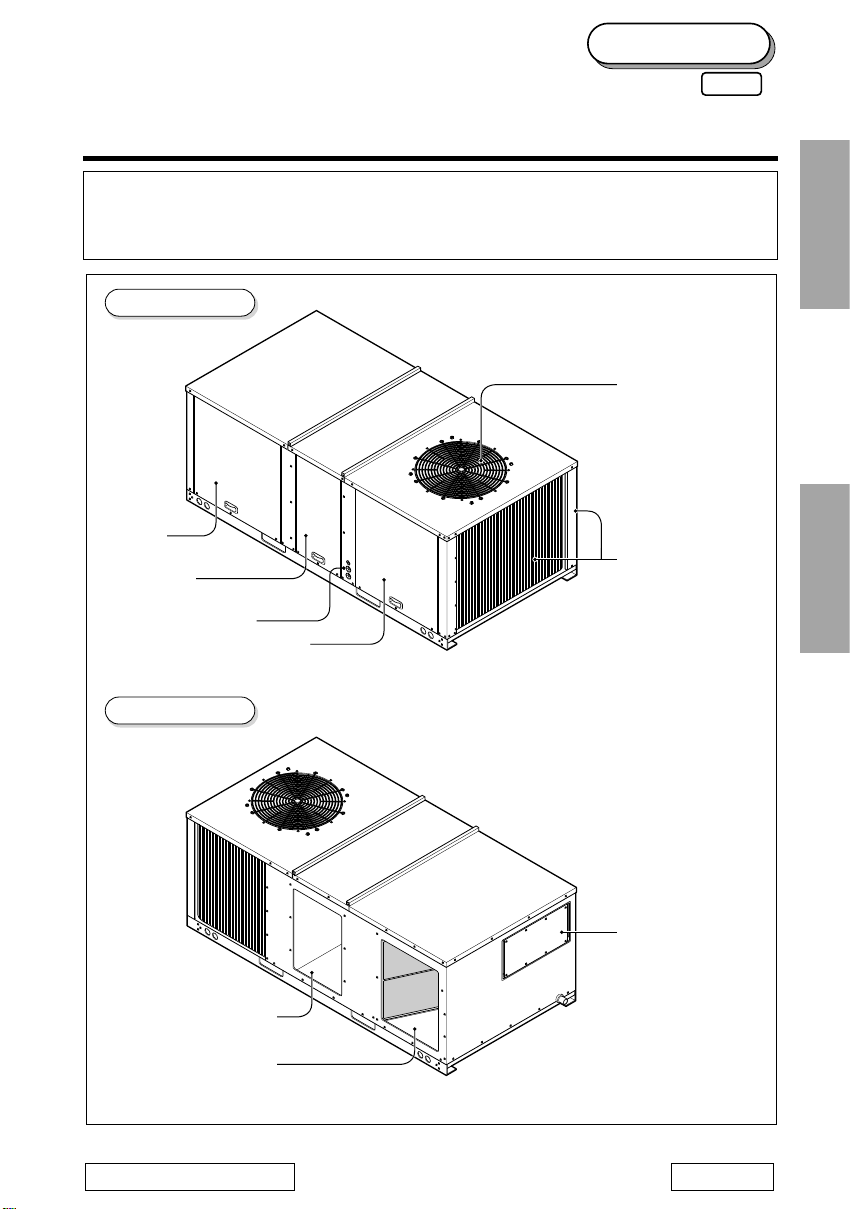
Air Outlet Vents
Filter
Access Panel
E/Heater
Access Panel
Unit Power Wires
Control and Compressor
Access Panel
Air Intake Vents
Refresh
Air Hood
Supply
(Side)
(Rear)
Return
Front View
Rear View
File Tab Position: 4 Rev. No.: 1
LK-IM-12
50Hz
ESPAÑOL

2
1.The following should be always observed for safety ...............................3
2. Dimensional Data ........................................................................................4
3. Installation of Unit .......................................................................................6
4. Ductwork ......................................................................................................7
5. Condensate Drain Piping ...........................................................................8
6. Filter Installation .........................................................................................8
7. Installation of remote controller ................................................................9
8. Electrical Wiring ........................................................................................10
9. Control Wiring ...........................................................................................13
10. Start-Up Pre-Start Quick Check List .....................................................15
11. Test Mode Procedure ..............................................................................16
12. Trial Run Mode ........................................................................................18
13. Evaporator Fan Adjustment ...................................................................19
14. Start-up ....................................................................................................20
15. Final installation Checklist and Maintenance ......................................22
TABLEOFCONTENTS
ENGLISH
3
1. The following should be always observed for safety
• Please report to or take consent by the supply authority before connecting to the system.
• Be sure to read "THE FOLLOWING SHOULD BE ALWAYS OBSERVED FOR SAFETY" before
installing the air conditioner.
• Be sure to observe the cautions specified here as they include important items related to safety.
• The indications and meanings are as follows.
• After reading this manual, be sure to keep it together with the owner's manual in a handy place .
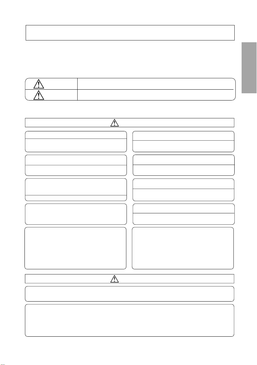
Could lead to death, serious injury, etc.
Do not install it yourself (customer).
Perform the installationsecurely referring to the
installation manual.
Install the unitsecurely in a place which canbear the
weight of theunit.
Perform electrical workaccording to the installation
manual and besure to use an exclusive circuit.
Attach the electricalpart cover and service panel to
the unit securely.
Be sure touse the part provided or specifiedparts for
the installation work.
Check that the refrigerant gas do not leak after
installation is completed.
Bodily injury can result from high voltage electrical
components or fast moving fan drives. For protection
from these inherent hazards during installation and
servicing, the electrical supply must be disconnected. If
operating checks must be performed with the unit
operating, it is the technician's responsibility to
recognize these hazards and proceed safely.
UNIT CONTAINS ANHCFC (R-22) REFRIGERANT
Section 608 paragraphC of the 1990 Clean AirAct states:
Effective July 1,1992 it shall be unlawful forany person, in the
course of maintaining,servicing, repairing or disposing of anair
conditioning system, toknowingly vent or release any CFCor
HCFC refrigerant minimalreleases (air purges of refrigerant
hoses) associated withgood faith attempts to recapture or
recycle are exemptedfrom the ban on venting.
Use the specifiedwires to connect the unit andthe
field installed cutoff switch box securely and attach
the wires firmlyto the terminal so the stressof the
wires is notapplied to the sections.
• Incomplete installation could cause injury due to fire, electric shock
or leakageof water. Consultthe dealer fromwhom you purchased
the unitor special installer.
• Incomplete installationcould cause a personal injury due to
fire, electric shock,noisy operation or distortion.
• When installedin an insufficient strong place, noisy operation
and distortion couldoccur.
• Incomplete connectingand fixing could cause fire.
• If thecapacity of the power circuit is insufficient or there is incomplete
electrical work, itcould result in a fire or an electric shock.
• Theuse of defective parts could cause aninjury or leakage of
water due to a fire, electricshock etc.
• Ifthe electrical part cover panel are notattached securely, it
could resultin a fire orelectric shock due todust, water etc.
Could lead to serious injury in particular environments when operated incorrectly.
WARNING
WARNING
CAUTION
Having perfect vacuum process in the factory, our units don't have drier but have filter in the
refrigerantcircuit.IncaseofrechargingR-22gasinthefield,
"DRIER" must be installed on the liquid line which is connected
from discharge part of condenser to intake part of evaporator. Because the refrigerant circuit is
capable of containing water with imperfect vacuum.
The equipment does not contain surge protection. To prevent damage caused by surge, transients
appropriate measures should be taken.
CAUTION
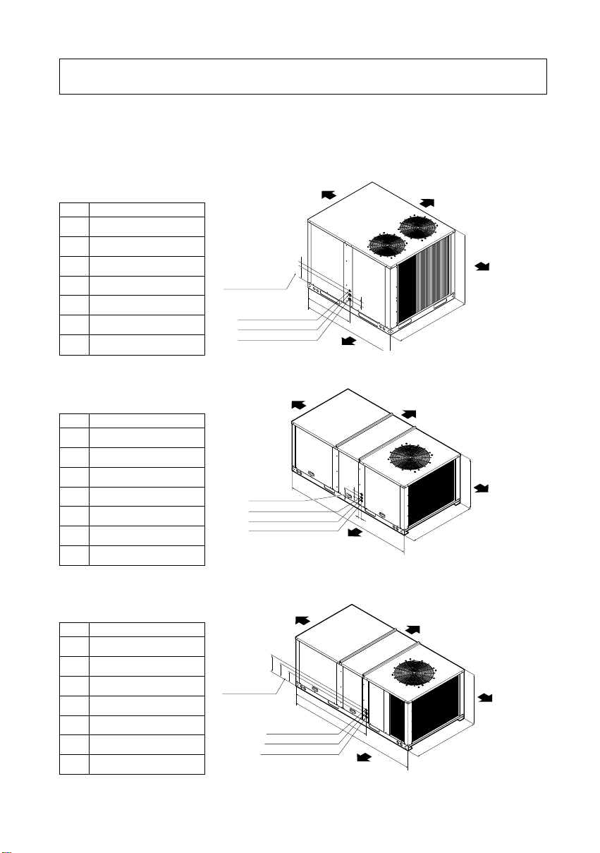
UNIT Dimensions (Figure 1A)
UNIT Dimensions (Figure 1B)
4
Single packaged cooling unit are designed for outdoor mounting with vertical condenser discharge. They
can be located either at ground level or on roof.
Each unit contains an operating charge of Refrigerant 22 as shipped.
E
G
F
Center Line of Hole
A
B
CLEARANCE 34"
CLEARANCE 16"(HORIZONTAL)
CLEARANCE 32"(DOWNFLOW)
CLEARANCE 34"
1" Dia. Hole Control Wires
1.5" Dia. Hole Power Wires
1.5" Dia. Hole Other Purpose
D
C
J
N
M
K
LL
1.5" Dia. Hole Power Wires
1.5" Dia. Hole Other Purpose
Center Line of Hole
1" Dia. Hole Control Wires
H
I
CLEARANCE 34"
CLEARANCE 16"
CLEARANCE 34"
CLEARANCE 46"
e
g
f
d
c
Center Line of Hole
a
b
CLEARANCE 34"
CLEARANCE 46"
CLEARANCE 16"(HORIZONTAL)
CLEARANCE 34"
1" Dia. Hole Control Wires
1.5" Dia. Hole Power Wires
1.5" Dia. Hole Other Purpose
Figure 1A
Figure 1B
Figure 1C
2. Dimensional Data
UNITS
LK-0580CC/0580HC/0680CH
A
B
C
D
E
F
G
41.93(1065)
43.70(1110)
50.39(1280)
29.49(749)
9.65(245)
2.36(60)
2.76(70)
UNITS
LK-0880CH/0880HH
H
I
J
K
L
M
N
35.04(890)
46.93(1159)
85.43(2170)
10.43(265)
2.76(70)
2.36(60)
3.54(90)
UNITS
LK-1080CH/1080HH
a
b
c
d
e
f
g
41.34(1050)
48.89(1242)
85.43(2170)
55.0(1397)
6.10(155)
8.46(215)
10.43(265)
UNIT Dimensions (Figure 1C)
Unit: inch(mm)
Unit: inch(mm)
ENGLISH
Horizontal Application Unit (Figure 1E)
Rear View Showing Duct Openings For Horizontal Air Flow
Horizontal Unit (Figure 1F)
Rear View Showing Duct Openings For Horizontal Air Flow
Down Flow Application Unit (Figure 1G)
(LK-0580CC, LK-0580HC)
LK-0580CC and LK-0580HC are
Convertible Unit
5
A
G
BCD
E
SUPPLY
RETURN
F
ab cd
e
f
S
U
P
P
L
Y
R
E
T
U
R
N
10,47(266)
9,25(235)
13,86(352)
6,26(159)
3,82(97)
16,38(416)
3,82(97)
22,28(566)
SUPPLY
RETURN
3/4" Condensate Location
Figure 1E
Rear View
Rear View
Figure 1F
Top View
Unit: inch(mm)
Figure 1G
Unit: inch(mm)
UNITS
LK-0580CC/0580HC LK-0680CH
A
B
C
D
E
F
G
13.86(352)
9.21(234)
10.47(266)
3.86(98)
4.33(110)
22.28(566)
16.38(416)
15.51(394)
8.43(214)
10.94(278)
2.87(73)
4.33(110)
24.25(616)
13.15(334)
a
b
c
d
e
f
15.47(393) 16.06(408) 24.53(623) 25.57(649.5)
16.18(411) 14.02(356) 9.17(233) 15.28(388)
18.82(478) 20.16(512) 24.53(623) 27.34(694.5)
2.40(61) 2.44(62) 2.36(60) 2.40(61)
5.35(136) 2.01(51) 5.08(129) 6.10(155)
26.89(683) 34.33(872) 40.24(1,022) 57.09(1,450)
Unit: inch(mm)
LK-0880CH
0880HH
LK-1080CH
1080HH
LK-1580CH
1580HH
LK-2080CH
2580CH
UNITS
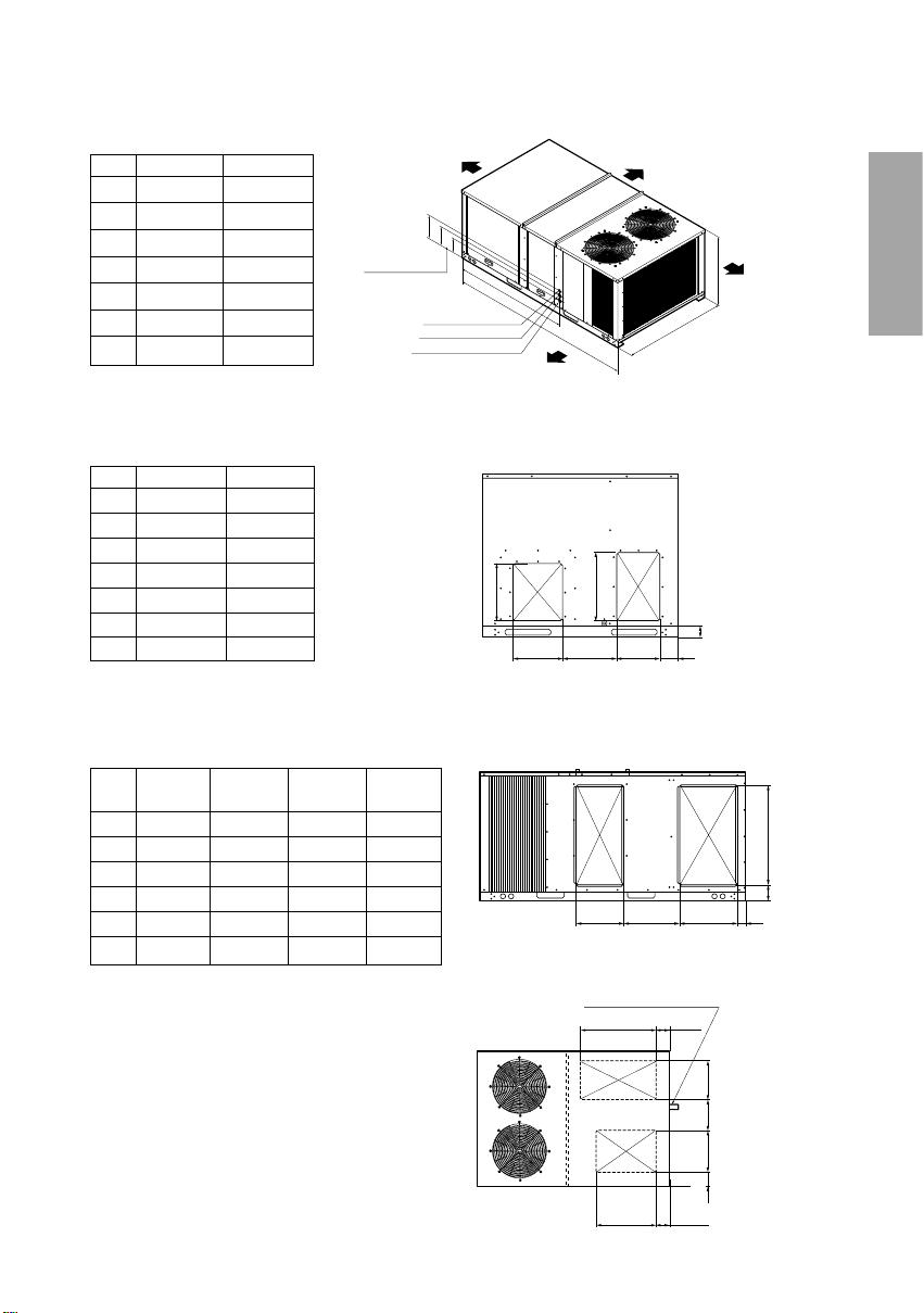
Horizontal Application Unit(Figure 1D)
Rear View Showing Duct Openings For Horizontal Air Flow
l
n
m
k
j
Center Line of Hole
h
i
CLEARANCE 34"
CLEARANCE 46"
CLEARANCE 16"(HORIZONTAL)
CLEARANCE
34"
1" Dia. Hole Control Wires
1.5" Dia. Hole Power Wires
1.5" Dia. Hole Other Purpose
Figura 1D
UNITS
LK-1580CH/1580HH
LK-2080CH/2580CH
h
i
j
k
l
m
n
47.44(1,205) 65.35(1,660)
69.53(1,766) 74.02(1,880)
95.98(2,438) 109.21(2,774)
63.11(1,603) 69.69(1,770)
6.29(160) 7.68(195)
8.66(220) 11.89(302)
11.02(280) -
Unit: inch(mm)
3-1. Inspection
1) Check for damage after unit is unloaded. Report promptly, to the carrier, any damage found to unit. Do
not drop unit.
2) Check the unit nameplate to determine if the unit voltage is correct for the application. Determine if
adequate electrical power is available. Refer to the application specifications.
3) Check to be sure the refrigerant charge has been retained during shipment. Access to 1/4" flare
pressure taps may be gained by removing compressor compartment access panel.
3-2. Location and Recommendations
1) Unit Support
If unit is to be roof mounted check building codes for weight distribution requirements.
2) Location and Clearances
Installation of unit should conform to local building codes and the National Electrical Code.
Select a location that will permit unobstructed airflow into the condenser coil and away from the fan
discharge and permit unobstructed service access into the compressor compartment. Suggested
airflow clearances and service clearances are given in Figure 1.
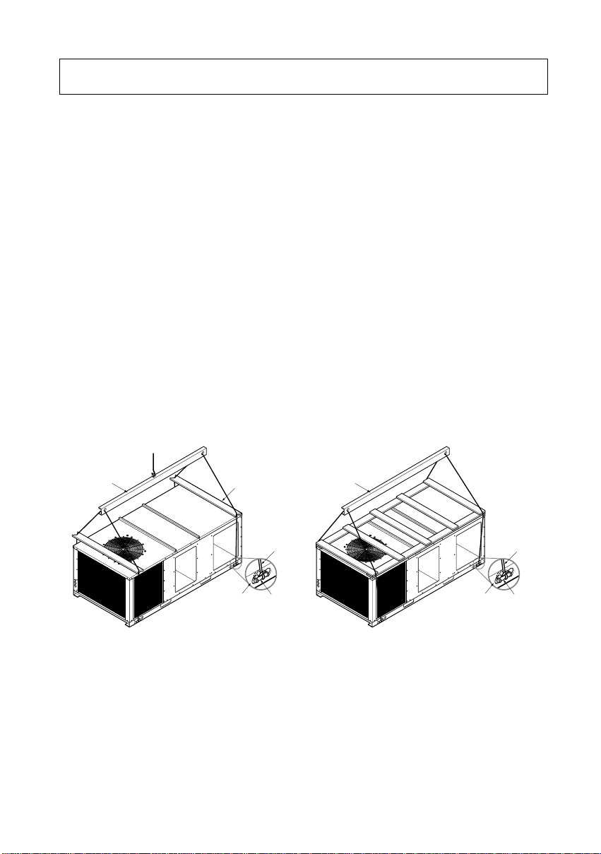
3) Placing and Rigging
Rig the unit using either belt or cable slings. The sling eyelet must be placed through the lifting holes in
the base rail of the unit. The point where the slings meet the lifting eyelet should be at least 6 feet
above the unit. Use spreader bars to prevent excessive pressure on the top of the unit during lifting.
Important: The use of "spreader bars" is required when hoisting the unit (prevents damage to
sides and top). Top crating can be used as spreader bars.
4) Roof Mounted Units
Downflow units(only 5RT) should be mounted on a roof curb when possible. On new roofs, the curb
should be welded directly to the roof deck. For existing construction, nailers must be installed under
the curb if welding is not possible. Be sure attach the downflow ductwork to the curb before setting unit
in place.
When installing the unit, it must be level to insure proper condensate flow from the unit drain pan.
5) Slab Mount
"For ground level installation, the unit base should be adequately supported and hold the unit near
level. The installation must meet the guidelines set forth in local codes."
6
3. Installation of Unit
ENGLISH
Lifting Beam
Cable
or Chain
ClevisHoles in Base
Rail
Spreader Bar
Lifting Beam
Cable
or Chain
ClevisHoles in Base
Rail
Recommended
Rigging Method
Figure 2
ENGLISH
1. Attaching Downflow Ductwork to The Roof Curb (below 5.0RT)
Supply and return air flanges are provided on the roof curb for easy duct installation. All duct work
must be run and attached to the curb before the unit is set into place.
2. Ductwork construction guidelines
Connections to the unit should be made with three-inch canvas connectors to minimize noise and
vibration transmission.
Elbows with turning vanes or splitters are recommended to minimize air noise and resistance.
The first elbow in the ductwork leaving the unit should be no closer than three times blower diameter to
avoid turbulence and back pressure.
3. Attaching Horizontal Ductwork to the Unit
All conditioned air ductwork should be insulated to minimize heating and cooling duct losses. Use
minimum of 2" of insulation with a vapor barrier. The outside ductwork must be weather proofed
between the unit and the building.
When attaching ductwork to a horizontal unit, provide a flexible water tight connection to prevent noise
transmission from the unit to the ducts. The flexible connection must be indoors and molded out of
heavy canvas.
Note: Do not draw the canvas taut between the solid ducts.
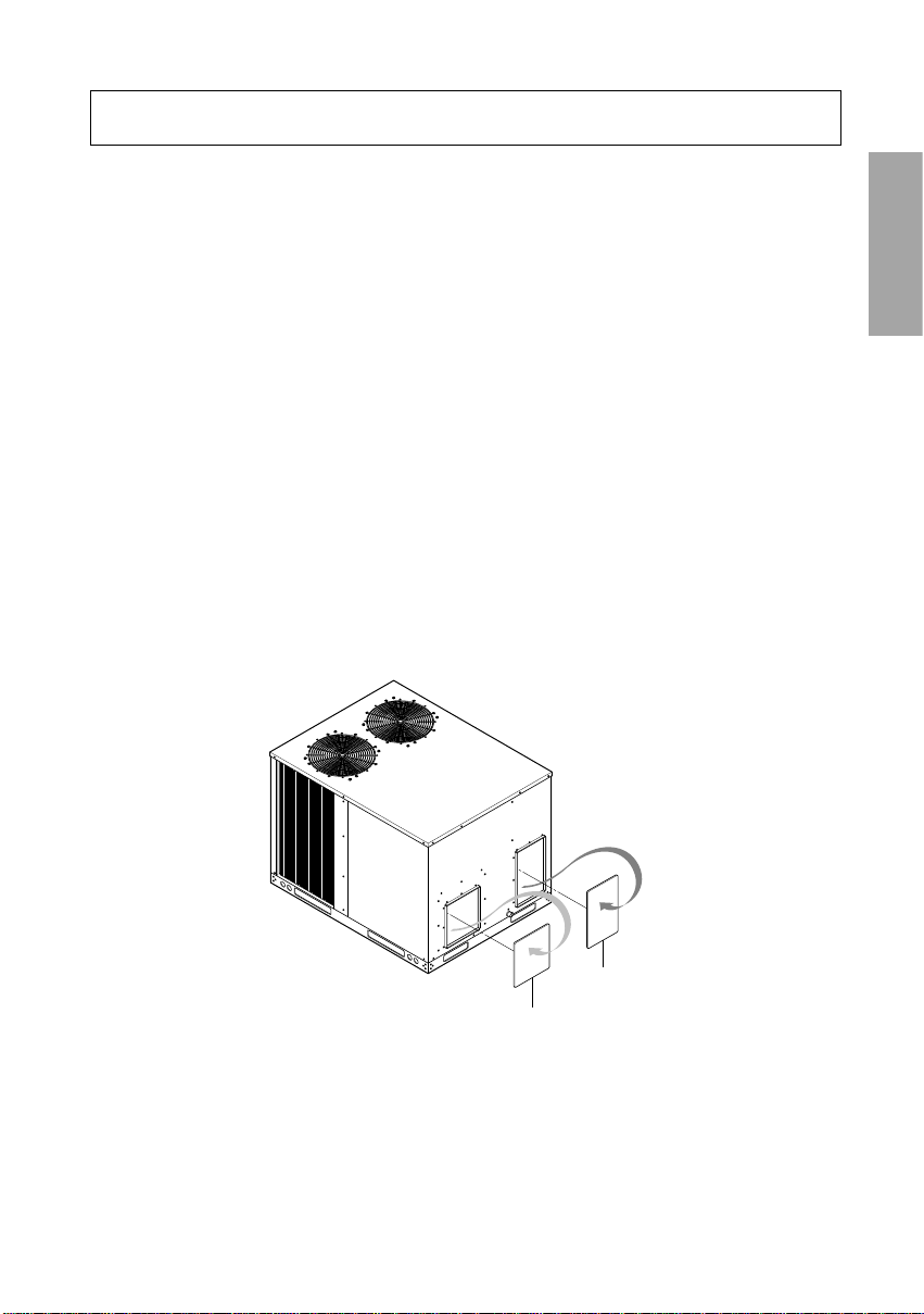
IMPORTANT(below 5.0RT)
To convert to downflow, remove covers from the downflow supply and return air opening(painted side
out) and secure with sheet metal screw (see Figure 3)
7
4. Ductwork
Figure 3
Note:
SUTTLY OPENING
1. Remove the screw nearest to the
opening and pull the panel firmly toward
the outside of the unit to disengage the
back attachment.
RETURN OPENING
2. Remove right hand screw and move
panel to the right or remove both
screws.
HORIZONTAL RETURN
AIR COVER
HORIZONTAL SUPPLY
AIR COVER
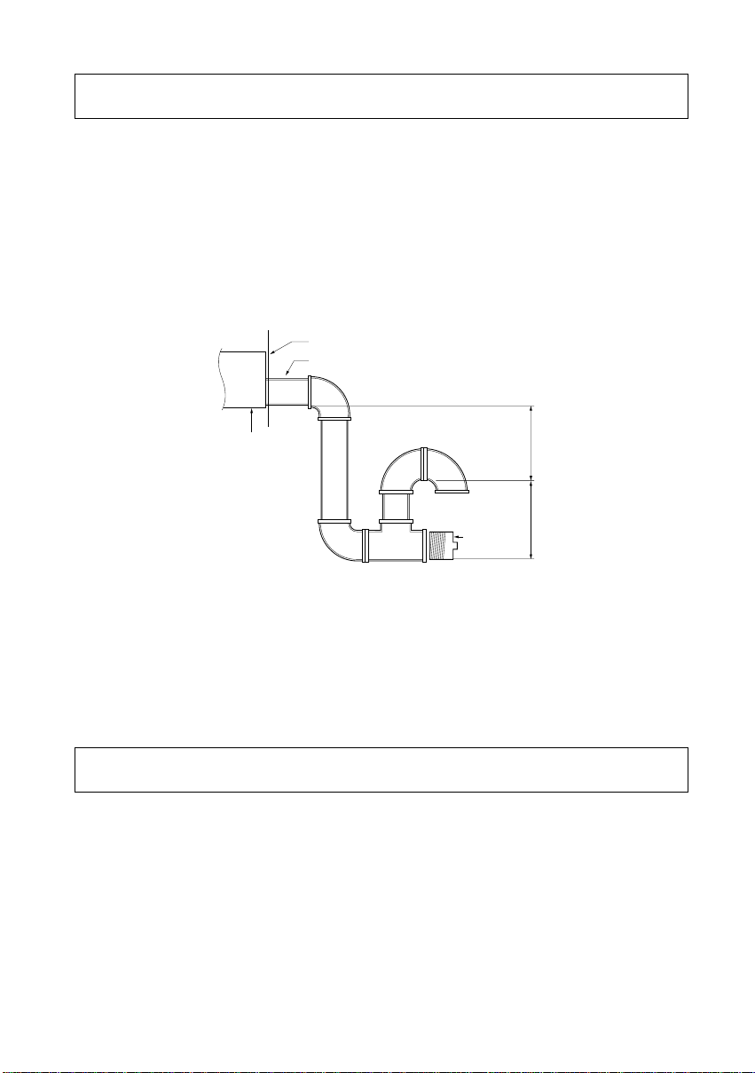
A. CONDENSATE DRAIN
A 3/4 inch male condensate drain connection is located on the corner of the unit next to the evaporator
section access panel. A trap should be installed and filled with water before starting the unit to avoid
air from being drawn through. Follow local codes and standard piping practices when running the drain
line. Pitch the line downward, away from the unit, and avoid long horizontal runs. See Figure 4.
Do not use reducing fittings in the drain lines.
The condensate drain must be:
1. Made of 3/4" pipe size.
2. Pitched 1/4" per foot to provide free drainage to convenient drain system.
3. Trapped
4. Must not be connected to closed drain system.
B. OUTDOOR COIL CONDENSATE DRAINAGE PRECAUTION
Condensate drains from the outdoor coil during the heating and defrost cycles. Normally this
condensate may be allowed to drain directly onto the ground/roof. A gravel bed is recommended to
prevent mud splashing.
WARNING : The unit should not be installed in an area where mud or ice could cause personal injury.
Remember that condensate drips from the outdoor coil during heat and defrost cycles
and that this condensate freezes when the temperature of the outdoor air is below
0°C(32°F)
■ Above 7.5RT
This Unit Filters are anti-bacteria and washable type.
Access to the filters is made by removing the evaporator fan access panel. Each unit ships with free
filters, as determined by unit size.
On the filter access panel at the left side of the unit, "FILTER ACCESS PANEL" label is attached.
■ Below 6.25RT
This unit is shipped without a filter and is the responsibility of the installer to secure a filter in
the return air ductwork.
Important: Do not operate unit without filters in place.
8
5. Condensate Drain Piping
6. Filter Installation
Figure 4
Panel Enclosure
3/4 Inch Male
Static pressure
Drain Pan
Cleanout
1.5 Inches1.5 Inches
Plug
 Loading...