

Page 1

- 1-1 -
[CONTENTS]
❍ SECTION 1.GENERAL
• SERVICING PRECAUTIONS . . . . . . . . . . . . . . . . . . . . . . . . . . . . . . . . . . . . . . . . . . . . . . . 1-2
• ESD PRECAUTIONS . . . . . . . . . . . . . . . . . . . . . . . . . . . . . . . . . . . . . . . . . . . . . . . . . . . . . 1-4
• SPECIFICATIONS . . . . . . . . . . . . . . . . . . . . . . . . . . . . . . . . . . . . . . . . . . . . . . . . . . . . . . . .1-5
• LOCATION OF CUSTOMER CONTROLS . . . . . . . . . . . . . . . . . . . . . . . . . . . . . . . . . . . . . . 1-6
❍ SECTION 2. AUDIO PART
• ELECTRICAL TROUBLESHOOTINGGUIDE. . . . . . . . . . . . . . . . . . . . . . . . . . . . . . . . . . . . 2-1
• BLOCK DIAGRAM . . . . . . . . . . . . . . . . . . . . . . . . . . . . . . . . . . . . . . . . . . . . . . . . . . . . . . . . 2-5
• SCHEMATIC DIAGRAMS . . . . . . . . . . . . . . . . . . . . . . . . . . . . . . . . . . . . . . . . . . . . . . . . . . 2-7
• WIRING DIAGRAM . . . . . . . . . . . . . . . . . . . . . . . . . . . . . . . . . . . . . . . . . . . . . . . . . . . . . . 2-19
• VOLTAGE SHEET ((IC&TR) . . . . . . . . . . . . . . . . . . . . . . . . . . . . . . . . . . . . . . . . . . . . . . . 2-21
• PRINTED CIRCUIT DIARGAMS . . . . . . . . . . . . . . . . . . . . . . . . . . . . . . . . . . . . . . . . . . . . 2-25
❍ SECTION 3.DVD PART
• ELECTRICAL TROUBLESHOOTING GUIDE . . . . . . . . . . . . . . . . . . . . . . . . . . . . . . . . . . . . .3-1
• DETAILS AND WAVEFORMS ON SYSTEM TEST AND DEBUGGING . . . . . . . . . . . . . . . . .3-8
• DVD PART SCHEMATIC DIAGRAMS . . . . . . . . . . . . . . . . . . . . . . . . . . . . . . . . . . . . . . . . .3-21
• VOLTAGE SHEET (IC & TR) . . . . . . . . . . . . . . . . . . . . . . . . . . . . . . . . . . . . . . . . . . . . . . . . 3-27
• PRINTED CIRCUIT DIAGRAM . . . . . . . . . . . . . . . . . . . . . . . . . . . . . . . . . . . . . . . . . . . . . . .3-29
❍ SECTION 4. EXPLODED VIEWS . . . . . . . . . . . . . . . . . . . . . . . . . . . . . . . . . . .4-1
❍ SECTION 5. SPEAKER PART . . . . . . . . . . . . . . . . . . . . . . . . . . . . . . . . . . . . .5-1
❍ SECTION 6. SPEAKER PART . . . . . . . . . . . . . . . . . . . . . . . . . . . . . . . . . . . . .6-1
• ELECTRICAL TROUBLESHOOTING GUIDE . . . . . . . . . . . . . . . . . . . . . . . . . . . . . . . . . . . . .6-1
• BLOCK DIAGRAM . . . . . . . . . . . . . . . . . . . . . . . . . . . . . . . . . . . . . . . . . . . . . . . . . . . . . . . .6-7
• SHEMATICDIAGRAMS . . . . . . . . . . . . . . . . . . . . . . . . . . . . . . . . . . . . . . . . . . . . . . . . . . . . .6-9
• WIRING DIAGRAM . . . . . . . . . . . . . . . . . . . . . . . . . . . . . . . . . . . . . . . . . . . . . . . . . . . . . . . 6-15
• PRINTED CIRCUIT DIAGRAM . . . . . . . . . . . . . . . . . . . . . . . . . . . . . . . . . . . . . . . . . . . . . . .6-17
• SPEAKER EXPLODED VIEWS . . . . . . . . . . . . . . . . . . . . . . . . . . . . . . . . . . . . . . . . . . . . . 6-23
• REPLACEMENT PARTS LIST . . . . . . . . . . . . . . . . . . . . . . . . . . . . . . . . . . . . . . . . . . . . . . .6-35
Page 2
- 1-2 -
SECTION 1. GENERAL
❏ SERVICING PRECAUTIONS
NOTES REGARDING HANDLING OF THE PICK-UP
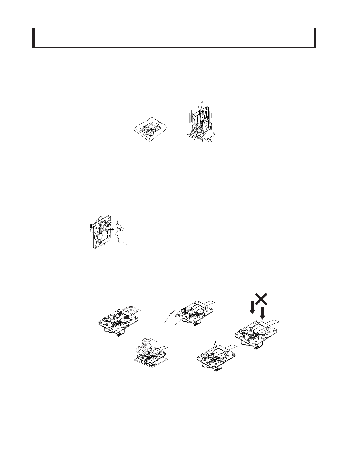
1. Notes for transport and storage
1) The pick-up should always be left in its conductive bag until immediately prior to use.
2) The pick-up should never be subjected to external pressure or impact.
2. Repair notes
1) The pick-up incorporates a strong magnet, and so should never be brought close to magnetic materials.
2) The pick-up should always be handled correctly and carefully, taking care to avoid external pressure and
impact. If it is subjected to strong pressure or impact, the result may be an operational malfunction and/or
damage to the printed-circuit board.
3) Each and every pick-up is already individually adjusted to a high degree of precision, and for that reason
the adjustment point and installation screws should absolutely never be touched.
4) Laser beams may damage the eyes!
Absolutely never permit laser beams to enter the eyes!
Also NEVER switch ON the power to the laser output part (lens, etc.) of the pick-up if it is damaged.
5) Cleaning the lens surface
If there is dust on the lens surface, the dust should be cleaned away by using an air bush (such as used
for camera lens). The lens is held by a delicate spring. When cleaning the lens surface, therefore, a cotton
swab should be used, taking care not to distort this.
6) Never attempt to disassemble the pick-up.
Spring by excess pressure. If the lens is extremely dirty, apply isopropyl alcohol to the cotton swab. (Do
not use any other liquid cleaners, because they will damage the lens.) Take care not to use too much of
this alcohol on the swab, and do not allow the alcohol to get inside the pick-up.
Storage in conductive bag
Drop impact
NEVER look directly at the laser beam, and don’t let
contact fingers or other exposed skin.
Magnet
How to hold the pick-up
Conductive Sheet
Cotton swab
Pressure
Pressure
Page 3
- 1-3 -
NOTES REGARDING COMPACT DISC PLAYER REPAIRS
1. Preparations
1) Compact disc players incorporate a great many ICs as well as the pick-up (laser diode). These components
are sensitive to, and easily affected by, static electricity. If such static electricity is high voltage, components
can be damaged, and for that reason components should be handled with care.
2) The pick-up is composed of many optical components and other high-precision components. Care must be
taken, therefore, to avoid repair or storage where the temperature of humidity is high, where strong magnetism is present, or where there is excessive dust.
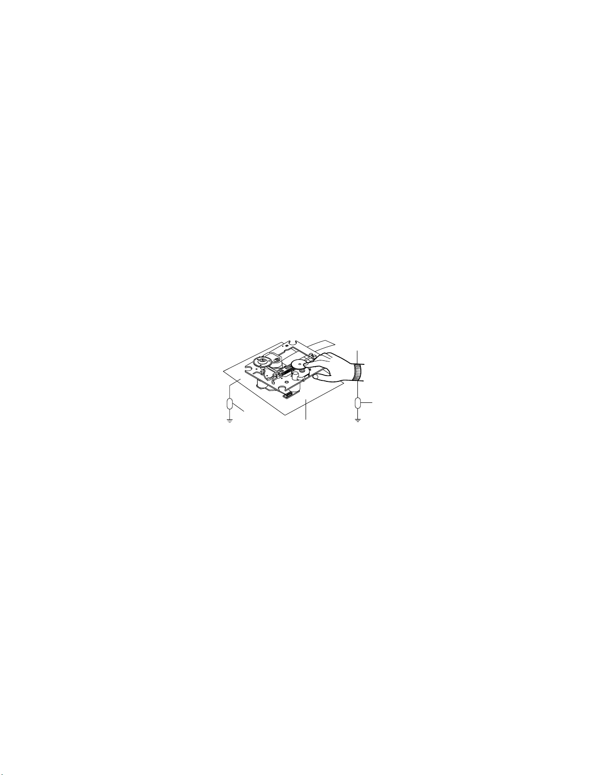
2. Notes for repair
1) Before replacing a component part, first disconnect the power supply lead wire from the unit
2) All equipment, measuring instruments and tools must be grounded.
3) The workbench should be covered with a conductive sheet and grounded.
When removing the laser pick-up from its conductive bag, do not place the pick-up on the bag. (This is
because there is the possibility of damage by static electricity.)
4) To prevent AC leakage, the metal part of the soldering iron should be grounded.
5) Workers should be grounded by an armband (1M Ω)
6) Care should be taken not to permit the laser pick-up to come in contact with clothing, in order to prevent static electricity changes in the clothing to escape from the armband.
7) The laser beam from the pick-up should NEVER be directly facing the eyes or bare skin.
Resistor
(1 Mohm)
Conductive
Sheet
Resistor
(1 Mohm)
Armband
Page 4
- 1-4 -
❏ ESD PRECAUTIONS
Electrostatically Sensitive Devices (ESD)
Some semiconductor (solid state) devices can be damaged easily by static electricity. Such components
commonly are called Electrostatically Sensitive Devices (ESD). Examples of typical ESD devices are integrated
circuits and some field-effect transistors and semiconductor chip components.The following techniques should
be used to help reduce the incidence of component damage caused by static electricity.
1. Immediately before handling any semiconductor component or semiconductor-equipped assembly, drain off
any electrostatic charge on your body by touching a known earth ground. Alternatively, obtain and wear a
commercially available discharging wrist strap device, which should be removed for potential shock reasons
prior to applying power to the unit under test.
2. After removing an electrical assembly equipped with ESD devices, place the assembly on a conductive sur-
face such as aluminum foil, to prevent electrostatic charge buildup or exposure of the assembly.
3. Use only a grounded-tip soldering iron to solder or unsolder ESD devices.
4. Use only an anti-static solder removal device. Some solder removal devices not classified as "anti-static" can
generate electrical charges sufficient to damage ESD devices.
5. Do not use freon-propelled chemicals. These can generate electrical charges sufficient to damage ESD
devices.
6. Do not remove a replacement ESD device from its protective package until immediately before you are
ready to install it. (Most replacement ESD devices are packaged with leads electrically shorted together by
conductive foam, aluminum foil or comparable conductive materials).
7. Immediately before removing the protective material from the leads of a replacement ESD device, touch the
protective material to the chassis or circuit assembly into which the device will by installed.
CAUTION : BE SURE NO POWER IS APPLIED TO THE CHASSIS OR CIRCUIT, AND OBSERVE ALL
OTHER SAFETY PRECAUTIONS.
8. Minimize bodily motions when handing unpackaged replacement ESD devices. (Otherwise harmless motion
such as the brushing together of your clothes fabric or the lifting of your foot from a carpeted floor can generate static electricity sufficient to damage an ESD device).
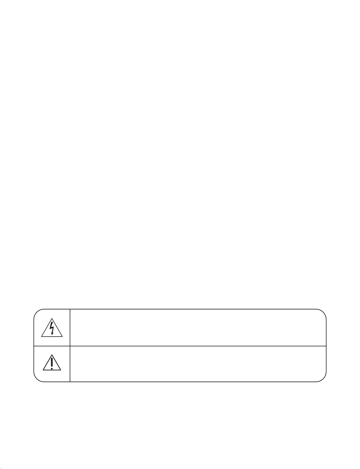
CAUTION. GRAPHIC SYMBOLS
THE LIGHTNING FLASH WITH APROWHEAD SYMBOL. WITHIN AN EQUILATERAL TRIANGLE, IS
INTENDED TO ALERT THE SERVICE PERSONNEL TO THE PRESENCE OF UNINSULATED “DANGEROUS VOLTAGE” THAT MAY BE OF SUFFICIENT MAGNITUDE TO CONSTITUTE A RISK OF
ELECTRIC SHOCK.
THE EXCLAMATION POINT WITHIN AN EQUILATERAL TRIANGLE IS INTENDED TO ALERT THE
SERVICE PERSONNEL TO THE PRESENCE OF IMPORTANT SAFETY INFORMATION IN SERVICE
LITERATURE.
Page 5
- 1-5 -
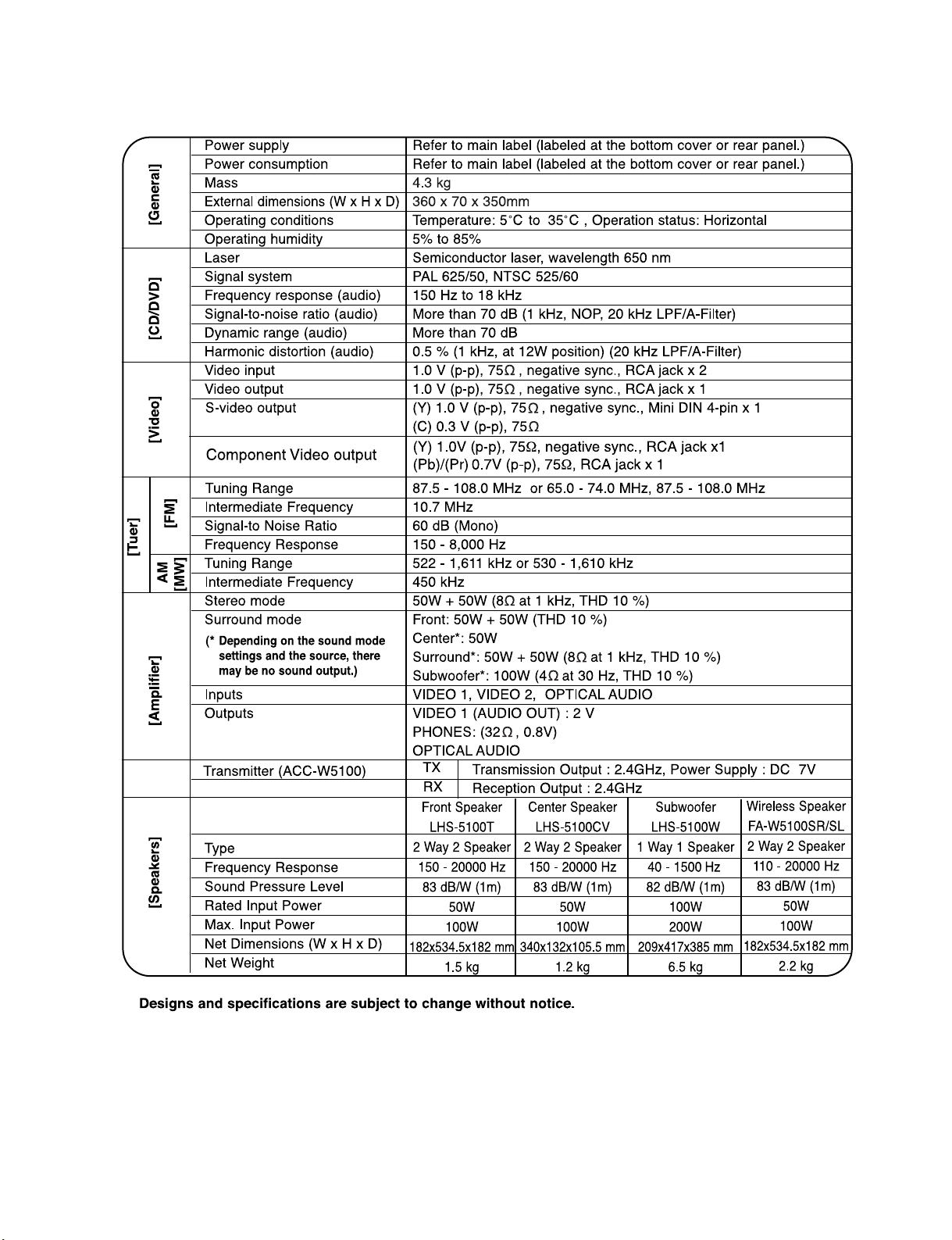
❏ SPECIFICATIONS
Page 6
- 1-6 -
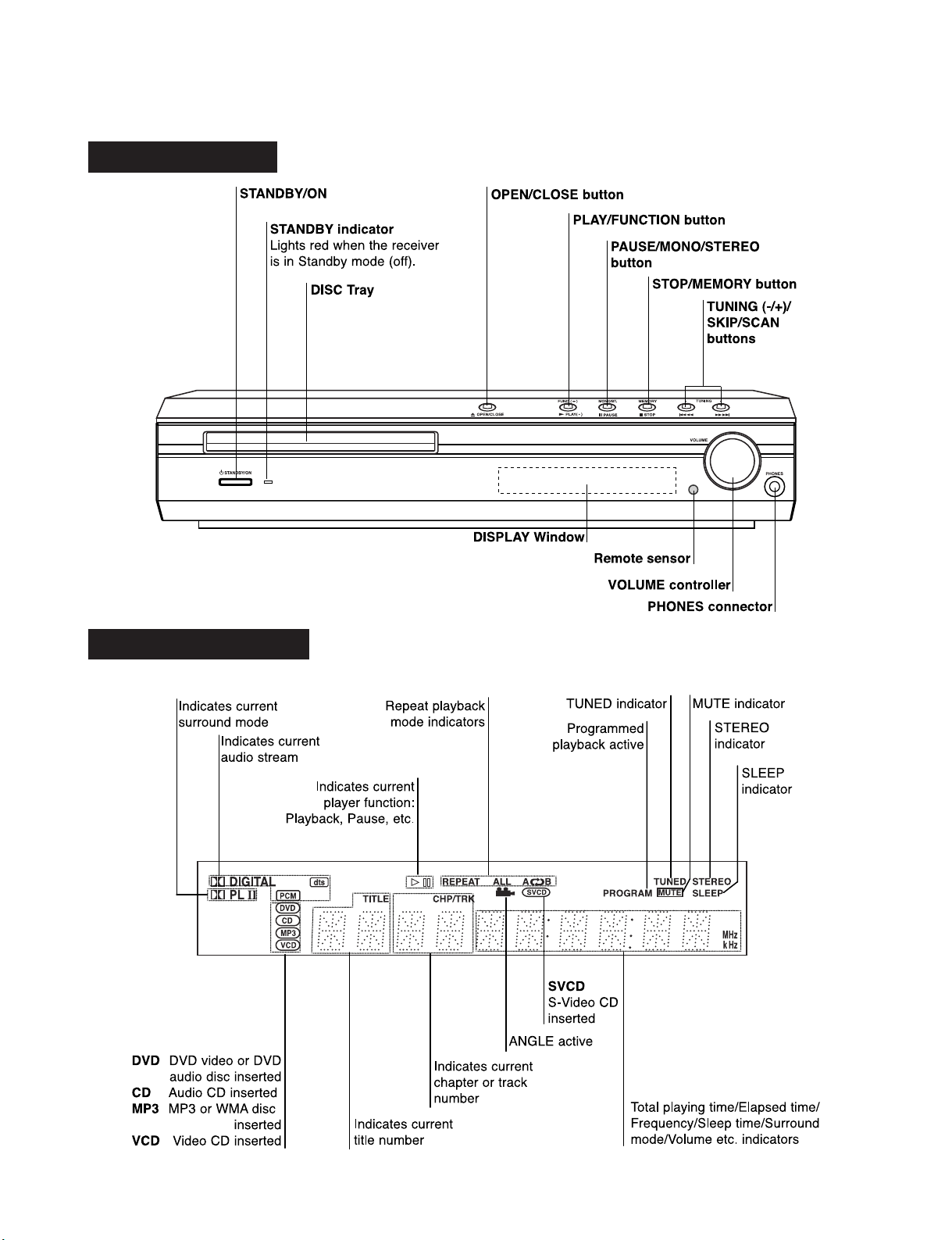
❏ LOCATION OF CUSTOMER CONTROLS
FRONT PANEL
DISPLAY WINDOW
Page 7
- 1-7 -
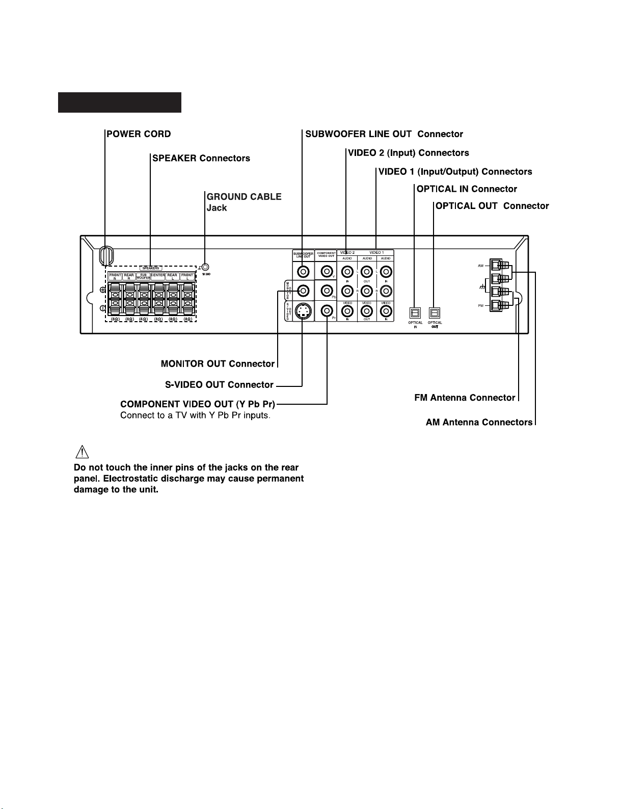
REAR PANEL
Page 8
- 1-8 -
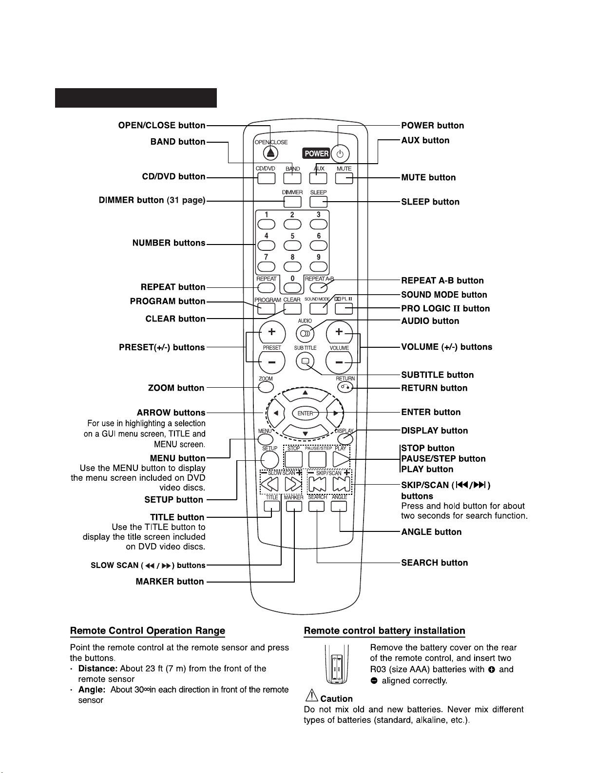
REMOTE CONTROL
Page 9
- 2-1 -
SECTION 2. AUDIO PART
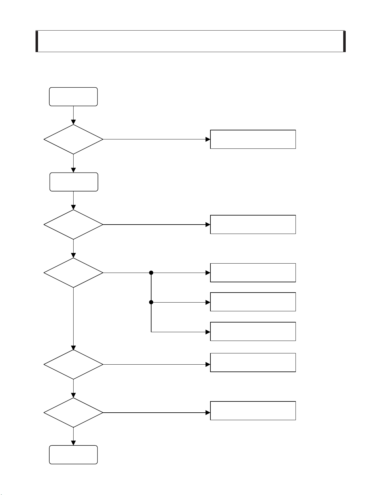
INSERT
POWER CORD.
TURN ON
THE RED LED?
IS POWER ON?
CHECK POWER PLUG
AND POWER SUPPLY CIRCUIT.
DOES INITIAL
READ WORK?
DOES IT PLAY?
YES
NO
YES
YES
OK
NO
YES
NO
NO
CHECK POWER SUPPLY CIRCUIT.
CHECK LASER CIRCUIT.
CHECK TRACKING SERVO CIRCUIT.
TURN POWER ON.
CHECK FOCUS CIRCUIT.
CHECK DISC.
DOES IT OUTPUT
AUDIO?
YES
NO
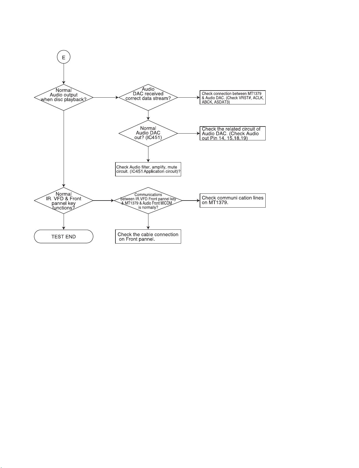
CHECK AUDIO CIRCUIT.
❏ ELECTRICAL TROUBLESHOOTING GUIDE
Page 10
- 2-2 -
2. AUDIO µ.COM CIRCUIT
Page 11
- 2-3 -
3. FRONT CIRCUIT (1/2)
POWER ON
TURN ON
THE GREEN LED?
CHECK IF THE
FRONT POWER
IS OK(*2).
IS DIGITRON
ON NORMALLY?
CHECK IF
THE HEADPHONE
IS OK.
YES
NO
YES
NO
YES
REFER TO SMPS PART.
CHECK IF
THE REMOCON
IS OK.
YES
CHECK IF
THE PN101/PN102
IS OK?
RECONNECT IT.
(REFER TO NOTICE *1).
CHECK IF
ALL BUTTENS
ARE OK.
YES
CHECK IF
THE VOLUME IS
OK.
YES
FRONT B/D OK.
YES
CHECK IF
THE VFD001 PINS
ARE OK.
CHECK PATTERN
AND RESOLDERING.
NO
YES
*1: When it i s needed to reconnect FPC cable into PN101/PN102,
short ZD972 + and screw(chassis GND) near to ZD972.
*2: PN101 Pins
PIN2 : -23.0V
PIN3 : -27.5V
PIN4 : 5.0V
PIN11 : -34.0V
PIN20 : 12.0V
NO
NO
Page 12

- 2-4 -
4.FRONT CIRCUIT (2/2)
Page 13
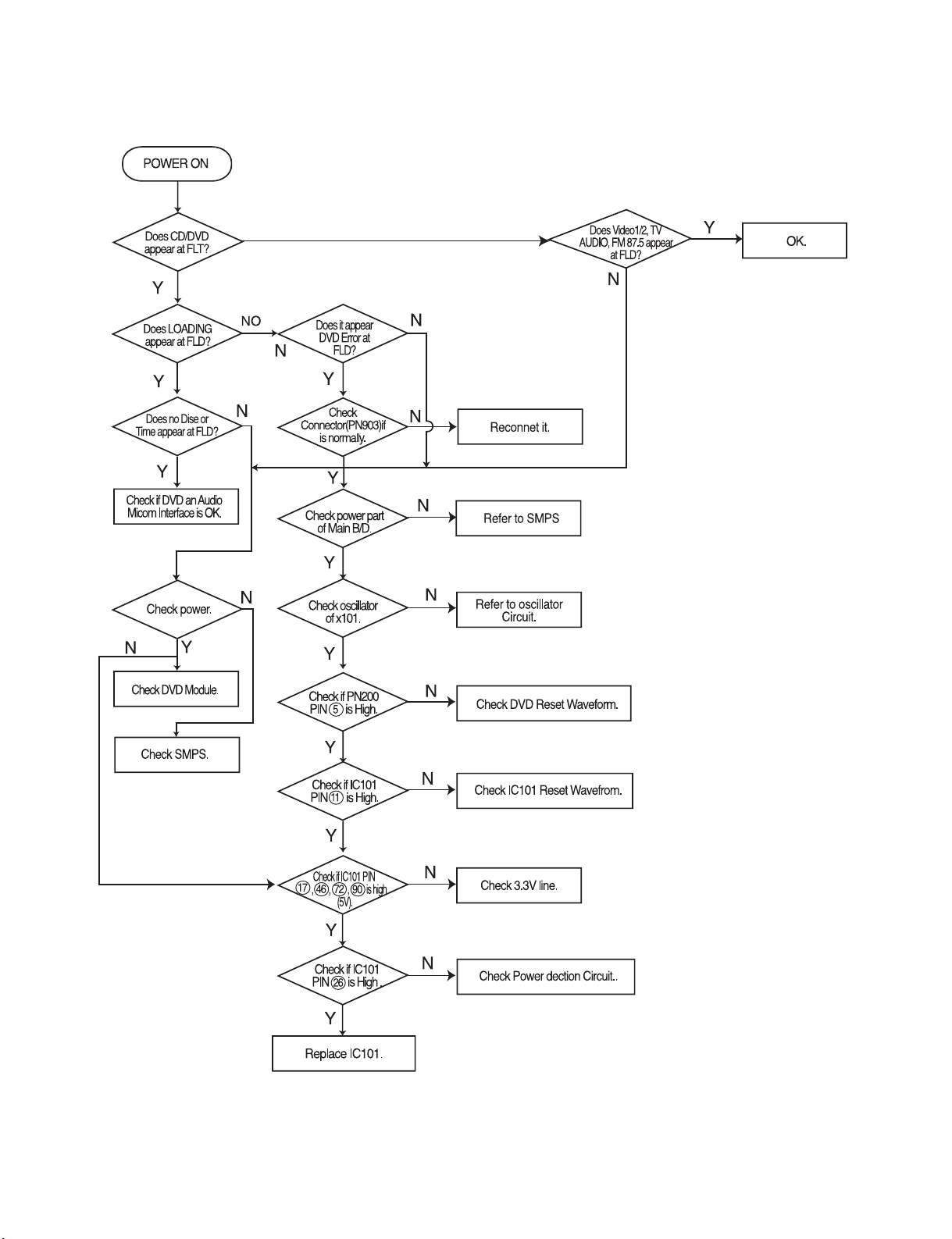
- 3-1 -
SECTION 3. DVD PART
DVD TROUBLESHOOTING GUIDE
1. Power check flow
❏ ELECTRICAL TROUBLESHOOTING GUIDE
Page 14
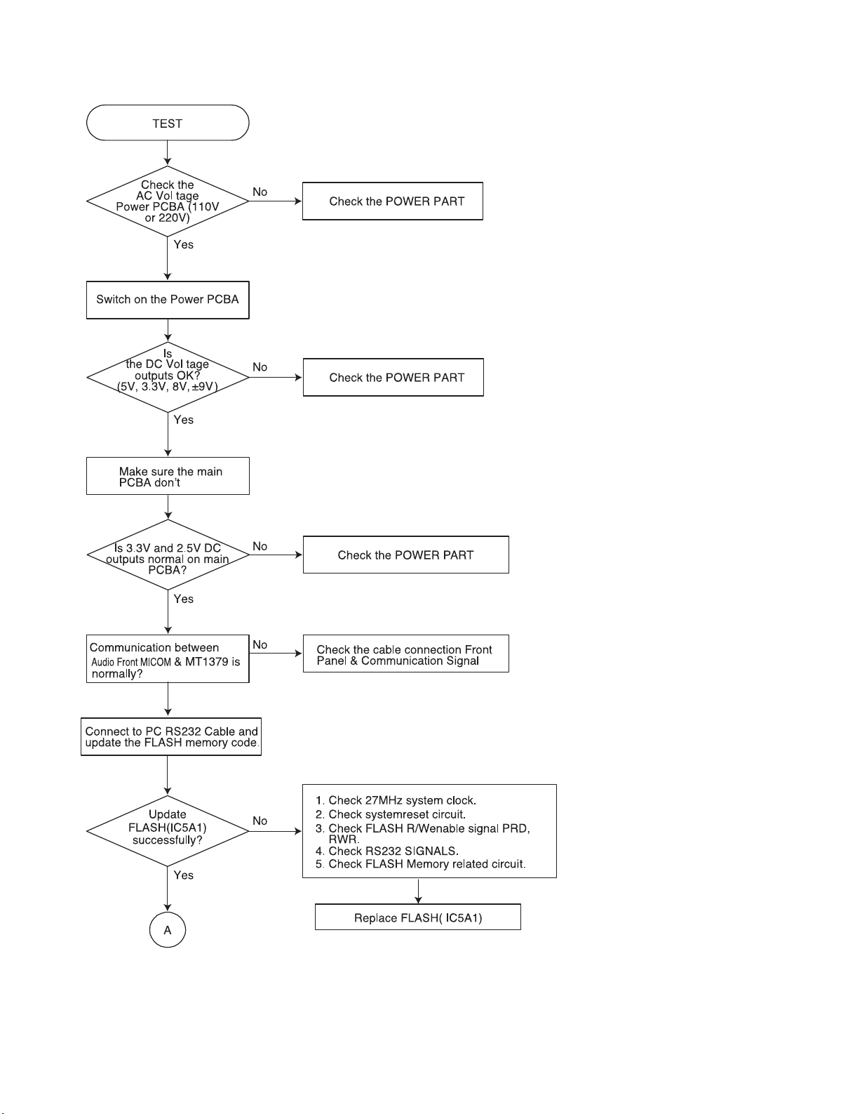
- 3-2 -
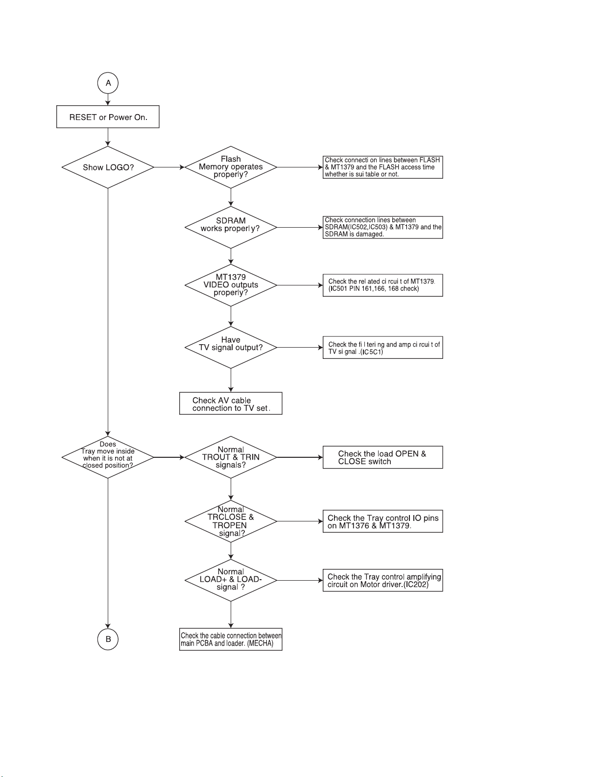
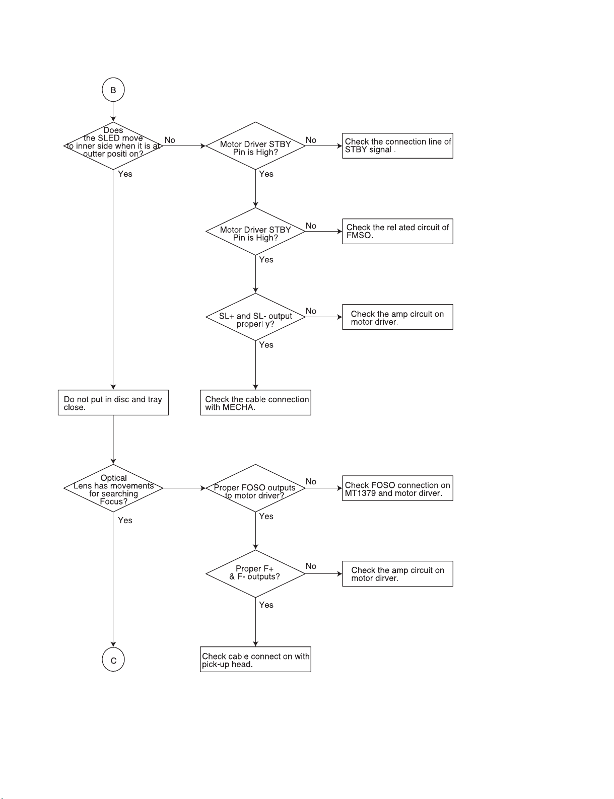
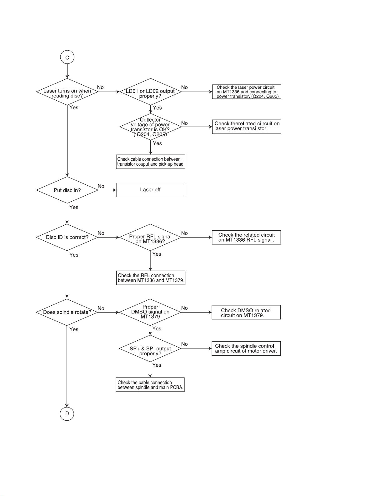
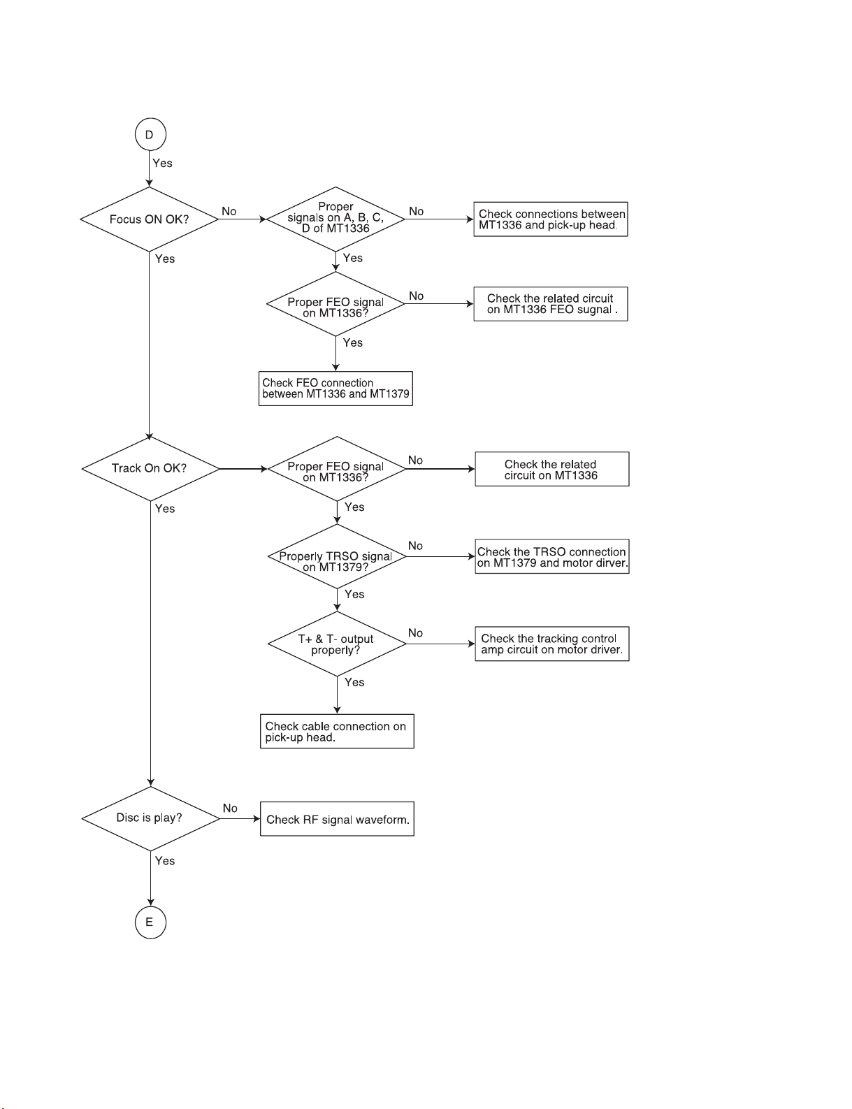
2. Test & debug flow
Page 15
- 3-3 -
Page 16
- 3-4 -
Page 17
- 3-5 -
Page 18
- 3-6 -
Page 19
- 3-7 -
Page 20
- 3-8 -
❏ DETAILS AND W VEFORMS ON SYSTEM TEST
AND DEBUGGING
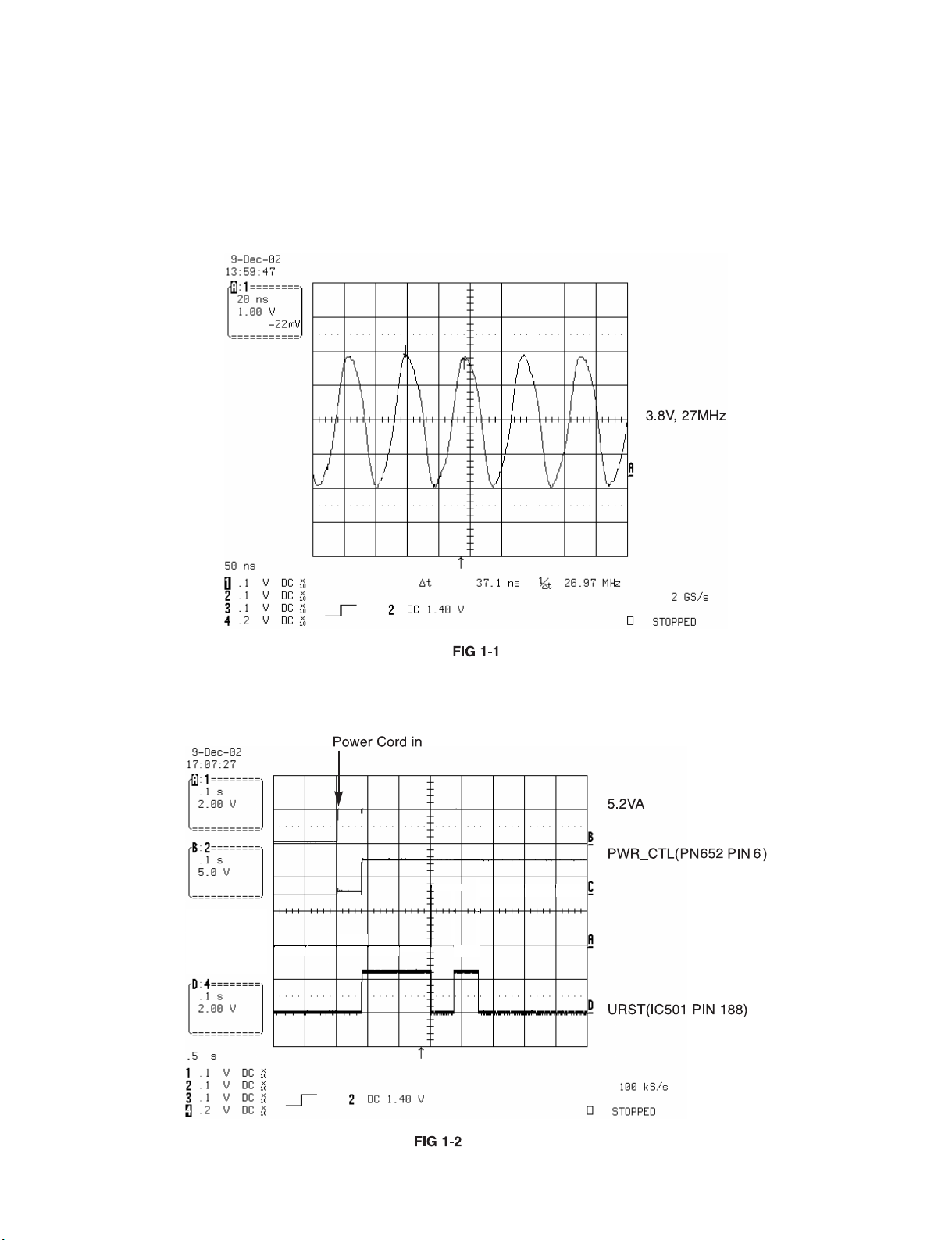
1. SYSTEM 27MHz CLOCK,RESET,FLASH R/W SIGNAL
1) MT1379 main clock is at 27MHz(X501)
2) MT1336 reset is high active
Page 21
- 3-9 -
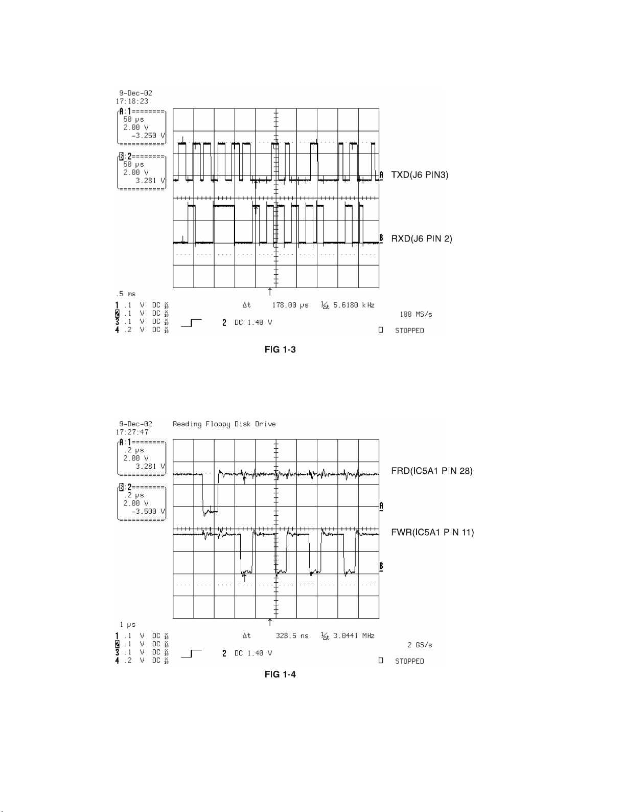
3) RS232 waveform during procedure(Downloading)
4) Flash R/W enable signal during download(Downloading)
Page 22
- 3-10 -
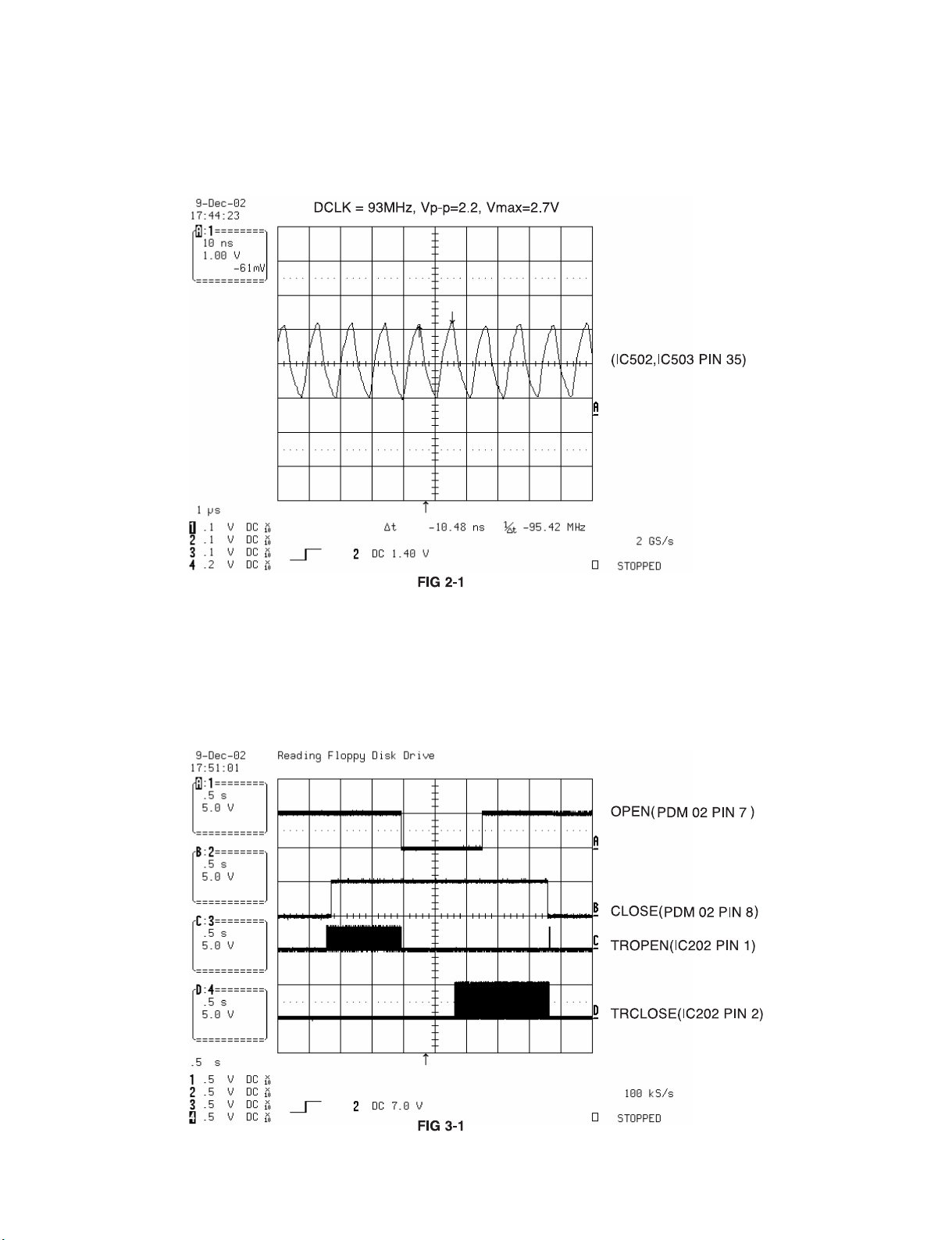
2. SDRAM CLOCK
1) MT1379 main clock is at 27MHz(X501)
3. TRAY OPEN/CLOSE SIGNAL
1) Tray open/close waveform
Page 23

- 3-11 -
2) Tray close waveform
3) Tray open waveform
Page 24

- 3-12 -
4. SLED CONTROL RELATED SIGNAL (NO DISC CONDITION)
5. LENS CONTROL RELATED SIGNAL(NO DISC CONDITION)
Page 25

- 3-13 -
6. LASER POWER CONTROL RELATED SIGNAL
(NO DISC CONDITION)
7. DISC TYPE JUDGEMENT W VEFORM
Page 26

- 3-14 -
Page 27

- 3-15 -
8. FOCUS ON W VEFORM
Page 28

- 3-16 -
9. SPINDLE CONTROL W VEFORM (NO DISC CONDITION)
Page 29

- 3-17 -
10. TRACKING CONTROL RELATED SIGNAL(System checking)
Page 30

- 3-18 -
11. RF W VEFORM
12. MT1379 AUDIO OPTICAL AND COAXIAL OUTPUT (ASPDIF)
Page 31

- 3-19 -
13. MT1379 VIDEO OUTPUT W VEFORM
1) Full colorbar signal(CVBS)
2) Y
Page 32

- 3-20 -
3) C
14. AUDIO OUTPUT FORM AUDIO DAC
1) Audio related Signal
Page 33

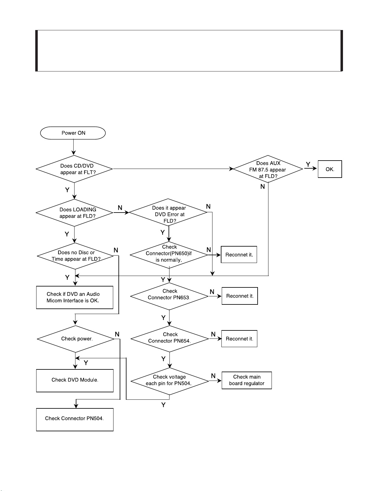
- 6-1 -
SECTION 6. SPEAKER PART
❏ ELECTRICAL TROUBLESHOOTING GUIDE
Page 34

- 6-2 -
Page 35

- 6-3 -
Page 36

- 6-4 -
Page 37

- 6-5 -
Page 38

- 6-6 -
MEMO
Page 39

❏ BLOCK DIAGRAM
2-5 2-6
Page 40

2-7 2-8
❏ SCHEMATIC DIAGRAMS
• FRONT &&POWER SCHEMATIC DIAGRAM
Page 41

2-9 2-10
• MICOM SCHEMATIC DIAGRAM
Page 42

2-11 2-12
• I//O SCHEMATIC DIAGRAM
Page 43

2-13 2-14
• DAP SCHEMATIC DIAGRAM
Page 44

2-15 2-16
• AMP SCHEMATIC DIAGRAM
Page 45

2-17 2-18
• SMPS SCHEMATIC DIAGRAM
Page 46

2-19 2-20
❏ WIRING DIAGRAM
Page 47

2-21 2-22
❏ VOLTAGE SHEET (IC&TR)
Page 48

2-23 2-24
Page 49

2-25 2-26
❏ PRINTED CIRCUIT DIAGRAMS
• MAIN P.C. BOARD (SOLDER SIDE)
Page 50

2-27 2-28
• MAIN P.C. BOARD (COMPONENT SIDE)
Page 51

2-29 2-30
• FRONT P.C. BOARD
Page 52

2-31 2-32
• SMPS P.C. BOARD
Page 53

3-21 3-22
❏ DVD PART SCHEMATIC DIAGRAMS
• MPEG SCHEMATIC DIAGRAM
Page 54

3-23 3-24
• SERVO SCHEMATIC DIAGRAM
Page 55

3-25 3-26
• INTERFACE SCHEMATIC DIAGRAM
Page 56

3-27 3-28
❏ VOLTAGE SHEET (IC&TR)
Page 57

3-29 3-30
❏ PRINTED CIRCUIT DIAGRAM
• DVD P.C. BOARD(SOLDER SIDE)
Page 58

3-31 3-32
• DVD P.C. BOARD (COMPONENT SIDE)
Page 59

4-1 4-2
SECTION 4. EXPLODED VIEWS
❏ CABINET AND MAIN FRAME SECTION
351
301
268
302
303
A46
A41
A26
275
266
267
A43
270
272
264
265
250
260
269
305
A47
TUNER
454
454
NOTE) Refer to “SECTION 6 REPLACEMENT
PARTS LIST” in order to look for the
part number of each part.
Page 60

4-3 4-4
• DECK MECHANISM EXPLODED VIEW
LOCA.NO. PART NO DESCRIPTION SPECIFICATION
A26 6721RJ0381A DECK ASSEMBLY,AUDIO DECK/MECHA DP-7A-HZ
A01 4861R-0016D CLAMP ASSEMBLY DECK/MECHA DISC DP-7C(7A) -HZ
A02 3041R-M018A BASE ASSEMBLY MAIN DP-7A-HZ
A03 3041R-M016D BASE ASSEMBLY SLED DP-7A -HZ
001 3300R-0547A PLATE CLAMP
002 5016H-1016B MAGNET CLAMP(LDM-R608,10*5,1*1.5T)
003 4860R-0021A CLAMP UPPER DP7
004 4930R-0402A HOLDER CLAMP DP-7A
010 6850R-GK12A CABLE,FLAT P=1.0 FFC UL2896(0.05X0.65) 11
011 3210R-M002A FRAME UP/DOWN MOLD DP7C
011A 6850R-JW14B CABLE,FLAT P=1.0 FFC UL2896(0.035X0.7) 23
012 5040R-0075B RUBBER DAMPER DP7 (CHUNG PUNG 30)
012 5040R-0075D RUBBER DAMPER DP7 (YAMAUCHI 30)
013 4400R-0006B BELT DECK/MECHA DP2-5, DP7C,DP7A OT
014 4470R-0055A GEAR PULLEY
015 6871RJ4415A PWB(PCB) ASSEMBLY,JACK(AUDIO) PWB(PCB) TOTAL LOADING-HZ
015A 4681R-1023G MOTOR ASSEMBLY DECK/MECHA LOADING-HZ
015B 4560R-0008A PULLEY MOTOR
015C 4680HP2001A MOTOR(MECH) RF-300CH-11440(SHAFT 6.05L)M/C
015C 4680R-E009A MOTOR(MECH) FEEDING RF300EH-1D390 MABUCHI
015C 4680R-E010A MOTOR(MECH) FEEDING BCZ3B51 SANKYO FOR DP7
015C 4680HP2011A MOTOR(MECH) PC200DG-21651C JOHNSON LOADING
017 4470R-0056A GEAR LOADING
018 4974R-0023A GUIDE UP/DOWN
020 3040R-D001A BASE MAIN MOLD DP-7AUDIO
021 4680R-C011A MOTOR(MECH) SPINDLE JCL9B68 SANKYO FOR COM
022 4681R-0034D MOTOR ASSEMBLY DECK/MECHA FEEDING DP-7C(7A)
024 4470R-0131A GEAR PINION DP7C
024A 5006R-0044A CAP SKEW-T DP7C
024B 5006R-0043A CAP SKEW DP7C
025 4470R-0130A GEAR MIDDLE DP7C
026 3390R-0012A TRAY DISC(DP-5RM MULTI)
028 4370R-0082B SHAFT DECK/MECHA PU R DP-7C OTHER
029 4370R-0082A SHAFT PU DP-7C
030 4471R-0013D GEAR ASSEMBLY DECK/MECHA RACK DP-7C(7A) -HZ
031 6716DPH005A PICK UP,DVD PVR-502W MITSUMI PLAYER H/HIGH
429 1SZZR-0012A SCREW,DRAWING B-TITE
430 1SZZH-1003A SCREW,DRAWING + D2.0 6MM SWRCH16A/NIY 4.5MM
430 1SZZH-1003A SCREW,DRAWING + D2.0 6MM SWRCH16A/NIY 4.5MM
431 1SZZH-1007B SCREW,DRAWING + D2.0 6MM SWRCH16A/ZNBK 4MM 1
431 1SZZH-1007B SCREW,DRAWING + D2.0 6MM SWRCH16A/ZNBK 4MM 1
432 1SZZR-0023B SCREW,DRAWING + 1 D1.7 L6.0 SWRCH16A/FZY RAC
433 1SZZR-0050A SCREW,DRAWING + 1 D2.0 L4.5 SWRCH16A/ZNY S-T
435 1SZZR-0011A SCREW,DRAWING MACHINE
Page 61

6-7 6-8
❏ BLOCK DIAGRAM
Page 62

6-9 6-10
❏ SHEMATIC DIAGRAMS
• SCHEMATIC DIAGRAM (ACC-W5100)
Page 63

6-11 6-12
• SCHEMATIC DIAGRAM (FA-W5100)
Page 64

6-13 6-14
• SMPS SCHEMATIC DIAGRAM (FA-W5100)
Page 65

6-15 6-16
❏ WIRING DIAGRAM
Page 66

6-17 6-18
❏ PRINTED CIRCUIT DIAGRAM
• ACC-W5100 P.C. BOARD
Page 67

6-19 6-20
• FA-W5100SL/SR MAIN P.C. BOARD
Page 68

6-21 6-22
• FA-W5100SL/SR SMPS P.C. BOARD
Page 69

6-23 6-24
❏ SPEAKER EXPLODED VIEWS
• Center Speaker
MODEL: LHS-5100CV
• Satellite Speaker
MODEL: LHS-5100T
857
859
856
853
854
855
858
858
850
852
851
760
756
755
757
758
754
753
752
759
751
750
LOCA.NO. PART NO DESCRIPTION SPECIFICATION REMARKS
850 3701RM0087A NET ASSEMBLY SPK LHS-5100C NET ASSY NSP
851 6400WETC02A SPEAKER,WOOFER 06N39EHC1319B EAW WOOFER 8OHM
852 3720RMM011A PANEL,AUDIO SPK LHS-W5100C MOLD FRONT NSP
853 6400DBHX01A SPEAKER,TWEETER SN11AP06D BALHAE TWEETER(DOME)
854 3040RMP015A BASE LHS-W5100C MOLD STAND HIPS
855 3610RM0030A FOOT SPK LHS-5100C OTHER PHI16*3T H
856 3110RMP040A CASE LHS-W5100C MOLD REAR HIPS NSP
857 6871RU9298A PWB(PCB) ASSEMBLY,SUBSET(AUDIO LHS-5100 2P TERMINAL + 1.5UF
858 353M050M SCREW,DRAWING + 2 D3.5 L10.0 MSWR3/FZY
859 353M050N SCREW,DRAWING + 1 D3.5 L14.0 FZMY2 FBK
860 6871RU9250J PWB(PCB) ASSEMBLY,SUBSET(AUDIO FE-6100C CENTER WIRE (5M) C/CH
A800 6401RM0089A SPEAKER ASSEMBLY 06N39EHC1319B EAW LHS-5100W
NSP :Non SVC Parts RUN DATA : 12-FEB.-04
LOCA.NO. PART NO DESCRIPTION SPECIFICATION REMARKS
750 3701RM0086A NET ASSEMBLY SPK LHS-5100T NET ASSY NSP
751 3790RMD001C WINDOW,DECO SPK LHS-5100T MOLD ACRYL SILK: NSP
752 6400WETC02A SPEAKER,WOOFER 06N39EHC1319B EAW WOOFER 8OHM
753 3720RMM012A PANEL,AUDIO SPK LHS-W5100T MOLD FRONT HIPS NSP
754 6400DBHX01A SPEAKER,TWEETER SN11AP06D BALHAE TWEETER(DOME)
755 3110RMP041A CASE LHS-W5100T MOLD REAR HIPS NSP
756 6871RU9298A PWB(PCB) ASSEMBLY,SUBSET(AUDIO LHS-5100 2P TERMINAL + 1.5UF
757 3040RMP017A BASE LHS-W5100T MOLD STAND HIPS
758 3610RM0004A FOOT RUBBER FE-197E/198AWE PHI 10 X
759 353M050M SCREW,DRAWING + 2 D3.5 L10.0 MSWR3/FZY
760 353M050N SCREW,DRAWING + 1 D3.5 L14.0 FZMY2 FBK
A700 6401RM0087A SPEAKER ASSEMBLY 06N39EHC1319B EAW LHS-5100T
ACCESSORY 6871RU9250G PWB(PCB) ASSEMBLY,SUBSET(AUDIO FE-6100 FRONT WIRE (5M) R/CH R
ACCESSORY 6871RU9250H PWB(PCB) ASSEMBLY,SUBSET(AUDIO FE-6100 FRONT WIRE (5M) L/CH W
NSP :Non SVC Parts RUN DATA : 12-FEB.-04
Page 70

6-25 6-26
MODEL: FA-W5100SL
FA-W5100SR
660
661
675
659
662
663
658
A52
A51
656
657
665
A50L/R
655
654
A54
A53
653
652
664
651
650
LOCA. NO. PART NO. SL SR DESCRIPTION SPECIFICATION REMARKS
A50L 6871RR4013A O PWB(PCB) ASSEMBLY,ROBOT(VCR) DA-W5100 WIRELESS RX_LCH NSP
A50R 6871RR4013B O PWB(PCB) ASSEMBLY,ROBOT(VCR) DA-W5100 WIRELESS RX_RCH NSP
A51 6871RP4013A O O PWB(PCB) ASSEMBLY,POWER(MULTI) DA-W5100 WIRELESS SMPS NSP
A5268 71RF4013A O O PWB(PCB) ASSEMBLY,FRONT(AUDIO) DA-W5100 WIRELESS CHANNEL SW NSP
A53 6871RJ4013A O O PWB(PCB) ASSEMBLY,JACK(AUDIO) DA-W5100 WIRELESS LED NSP
A54 6871RY4013A O O PWB(PCB) ASSEMBLY,Y/C(VCR) DA-W5100 WIRELESS TW NSP
A600 6401RM0090A O SPEAKER ASSEMBLY 06N39EHC1319B EAW FA-W5100SL VISION TECH
A600 6401RM0091A O SPEAKER ASSEMBLY 06N39EHC1319B EAW FA-W5100SR VISION TECH
650 3701RM0088A O O NET ASSEMBLY SPK FA-W5100 NET ASSY NSP
651 3790RMD001A O WINDOW,DECO SPK LHS-W5100 MOLD ACRYL SILK: NSP
651 3790RMD001B O WINDOW,DECO SPK FAW5100 MOLD ACRYL NSP
652 6400FETC01C O O SPEAKER,WOOFER 06N39EHC1319B EAW WOOFER 8OHM
653 3720RMM010A O O PANEL,AUDIO SPK FA-W5100SR/SL MOLD HIPS GR NSP
654 6400DBHX01C O O SPEAKER,TWEETER 111D10-LG03 BALHAE TWEETER(DOM
655 3110RMP037A O O CASE LHS-W5100SR/SL MOLD HIPS GRAY NSP
656 4810RM0004A O O BRACKET SPK LHS-W5100SR/SL PRESS SHIEL NSP
657 4920RCP014A O O HEAT SINK AL PR 78*20*40 FA-W6100S NSP
658 4940RMS001A O O KNOB SPK LHS-W5100SR/SL MOLD SLIDE
659 4810RM0005A O O BRACKET SPK LHS-W5100SR/SL PRESS BOTTO NSP
660 3110RMP038A O O CASE LHS-W5100SR/SL MOLD HIPS NSP
661 6871RU9298A O O PWB(PCB) ASSEMBLY,SUBSET LHS-5100 2P TERMINAL + 1.5UF
662 3040RMP012A O O BASE LHS-W5100 MOLD SKP STAND HIPS
663 3610RM0006A O O FOOT RUBBER FE-5000TE PHI 20 X 3T H
664 353M051H O O SCREW,DRAWING + 1 D4.0 L14 FZMY2 BLK
665 353-025P O O SCREW,DRAWING TAPTITE 3X12 FBK
675 6410RKHK07A O O POWER CORD KJP-170(ST-HS:95MM) KUKJE SAA 2400MM GP390
NSP :Non SVC Parts RUN DATA : 12-FEB.-04
Page 71

6-27 6-28
MODEL: LHS-5100W
953
951
952
950
954
955
962
LOCA.NO. PART NO DESCRIPTION SPECIFICATION REMARKS
950 3720RMF060A PANEL,FRONT SPK LHS-D6530W MOLD SILVER SPR NSP
951 3701RM0047A NET ASSEMBLY SPK LHS-D6530W NET ASSY NSP
952 6400WETN01A SPEAKER,WOOFER 18P90EHC1391 EAW WOOFER 4 OHM
953 3091RMW058A CABINET ASSEMBLY SPK LHS-D6530W WOOD CABINET NSP
954 6871RU9271F PWB(PCB) ASSEMBLY,SUBSET(AUDIO LHS-D6230W SUB WOOFER 2.5M, OR
955 3610RM0002A FOOT RUBBER FE-5620WE STANDARD 4 EA
962 353M050C SCREW,DRAWING BH 3.5X16 FBK
A900 6401RM0068A SPEAKER ASSEMBLY 18P90EHC2214 EAW LHS-D6530W (S
NSP :Non SVC Parts RUN DATA : 12-FEB.-04
Page 72

6-29 6-30
MODEL: ST-W5100(OPTION)
ST-W5200(OPTION)
664
680
681
682
683
684
666
663
LOCA. NO. PART NO. QTY DESCRIPTION SPECIFICATION REMARKS
663 3610RM0006A 16 FOOT RUBBER FE-5000TE PHI 20 X 3T H
664 353M051H 32 SCREW,DRAWING + 1 D4.0 L14 FZMY2 BLK
666 353M025R 32 SCREW,DRAWING + 2 D3.0 L10.0 S20C-D/BK WASHE
680 3040RMP013A 4 BASE LHS-W5100SR/SL MOLD JOINT SPK/
681 3110RMP039A 4 CASE LHS-W5100SR/SL OTHER AL EXTRUT
682 3040RMP014A 4 BASE LHS-W5100SR/SL MOLD STAND (AL)
683 3508RMP050A 8 DECORATION ST-W5100 PRESS BASE WEIGHT SEC
684 3508RMP050B 4 DECORATION ST-W5100 PRESS BASE WEIGHT 1.6
NSP :Non SVC Parts
LOCA. NO. PART NO. QTY DESCRIPTION SPECIFICATION REMARKS
663 3610RM0006A 8 FOOT RUBBER FE-5000TE PHI 20 X 3T H
664 353M051H 16 SCREW,DRAWING + 1 D4.0 L14 FZMY2 BLK
666 353M025R 16 SCREW,DRAWING + 2 D3.0 L10.0 S20C-D/BK WASHE
680 3040RMP013A 2 BASE LHS-W5100SR/SL MOLD JOINT SPK/
681 3110RMP039A 2 CASE LHS-W5100SR/SL OTHER AL EXTRUT
682 3040RMP014A 2 BASE LHS-W5100SR/SL MOLD STAND (AL)
683 3508RMP050A 4 DECORATION ST-W5100 PRESS BASE WEIGHT SEC
684 3508RMP050B 2 DECORATION ST-W5100 PRESS BASE WEIGHT 1.6
NSP :Non SVC Parts
Page 73

6-31 6-32
MODEL: ACC-W5100
551
552
554
553
555
562
A40
556
562
557
LOCA.NO. PART NO DESCRIPTION SPECIFICATION REMARKS
551 3508RCD002D DECORATION ACC-W5100 MOLD PLATE
552 3110RCD001B CASE ACC-W6100 MOLD FRONT LHEMK
553 3806RC0039A DECO CAP ACC-W6100
554 3806RC0040A DECO ANT ACRYL ACC-W6100
555 3550RC0393A COVER ANT ACC-W6100
556 3110RCD002A CASE ACC-W6100 MOLD BOTTOM
557 447-059J CUSHION AUDIO FOOT,CD-V952/V957
562 353-645A SCREW,DRAWING SPECIAL TAPPING 2X8 BK
565 6634BSTR07D ADAPTER,AC-DC PN003A1A 7V 400MA POWERNET
568 3890RCC062Y BOX SW-6100 SPK - 1
569 3920RCE062A PACKING,CASING SW6100ACCPACK 0.02 100 EPS 8 1
570 6410RKDK01A POWER CORD KJP-170 KKJ-201A KUKJE SAA 1800MM
580 6850R-NAB03 CABLE,USB USB TO 2 SPEAKER STRIP TYPE S NSP
A40 6871RT4013A PWB(PCB) ASSEMBLY,TUNER/IF DA-W5100 WIRELESS TX
ANT101 5010R-R005A ANTENNA,ROD DIPOLE ANTENNA KBE-2400S KOSAN
NSP :Non SVC Parts RUN DATA : 12-FEB.-04
 Loading...