

LG LH70A Service Manual
SERVICE MANUAL
SERVICE MANUAL
CAUTION
BEFORE SERVICING THE UNIT, READ THE “SAFETY PRECAUTIONS”
IN THIS MANUAL.
Internal Use Only
Website http://biz.lgservice.com
AUGUST, 2015
MODEL: LH70A (LH70A, LH70A-S)
MODEL: LH70A
(LH70A, LH70A-S)
Multimedia
Speaker System
P/NO : AFN77277035

CONTENTS
SECTION 1 ........ GENERAL
SECTION 2 ........ CABINET & MAIN CHASSIS
SECTION 3 ........ ELECTRICAL
SECTION 4 ........ REPLACEMENT PARTS LIST
1-1

SECTION 1
GENERAL
CONTENTS
ESD PRECAUTIONS ......................................................................................................................................... 1-3
HIDDEN KEY MODE ......................................................................................................................................... 1-4
THE PROCESS OF UPDATING SOFTWARE .................................................................................................. 1-5
SPECIFICATIONS ........................................................................................................................................... 1-11
1-2
ESD PRECAUTIONS
Electrostatically Sensitive Devices (ESD)
Some semiconductor (solid state) devices can be damaged easily by static electricity. Such components
commonly are called Electrostatically Sensitive Devices (ESD). Examples of typical ESD devices are integrated
circuits and some field-effect transistors and semiconductor chip components. The following techniques should
be used to help reduce the incidence of component damage caused by static electricity.
1. Immediately before handling any semiconductor component or semiconductor-equipped assembly, drain off
any electrostatic charge on your body by touching a known earth ground. Alternatively, obtain and wear a
commercially available discharging wrist strap device, which should be removed for potential shock reasons
prior to applying power to the unit under test.
2. After removing an electrical assembly equipped with ESD devices, place the assembly on a conductive surface
such as aluminum foil, to prevent electrostatic charge buildup or exposure of the assembly.
3. Use only a grounded-tip soldering iron to solder or unsolder ESD devices.
4. Use only an anti-static solder removal device. Some solder removal devices not classified as "anti-static" can
generate electrical charges sufficient to damage ESD devices.
5. Do not use freon-propelled chemicals. These can generate electrical charges sufficient to damage ESD
devices.
6. Do not remove a replacement ESD device from its protective package until immediately before you are
ready to install it. (Most replacement ESD devices are packaged with leads electrically shorted together by
conductive foam, aluminum foil or comparable conductive materials).
7. Immediately before removing the protective material from the leads of a replacement ESD device, touch the
protective material to the chassis or circuit assembly into which the device will by installed.
CAUTION : BE SURE NO POWER IS APPLIED TO THE CHASSIS OR CIRCUIT, AND OBSERVE ALL OTHER
SAFETY PRECAUTIONS.
8. Minimize bodily motions when handing unpackaged replacement ESD devices. (Otherwise harmless motion
such as the brushing together of your clothes fabric or the lifting of your foot from a carpeted floor can generate
static electricity sufficient to damage an ESD device).
CAUTION. GRAPHIC SYMBOLS
THE LIGHTNING FLASH WITH APROWHEAD SYMBOL. WITHIN AN EQUILATERAL TRIANGLE, IS
INTENDED TO ALERT THE SERVICE PERSONNEL TO THE PRESENCE OF UNINSULATED
“DANGEROUS VOLTAGE” THAT MAY BE OF SUFFICIENT MAGNITUDE TO CONSTITUTE A RISK OF
ELECTRIC SHOCK.
THE EXCLAMATION POINT WITHIN AN EQUILATERAL TRIANGLE IS INTENDED TO ALERT THE
SERVICE PERSONNEL TO THE PRESENCE OF IMPORTANT SAFETY INFORMATION IN SERVICE
LITERATURE.
1-3
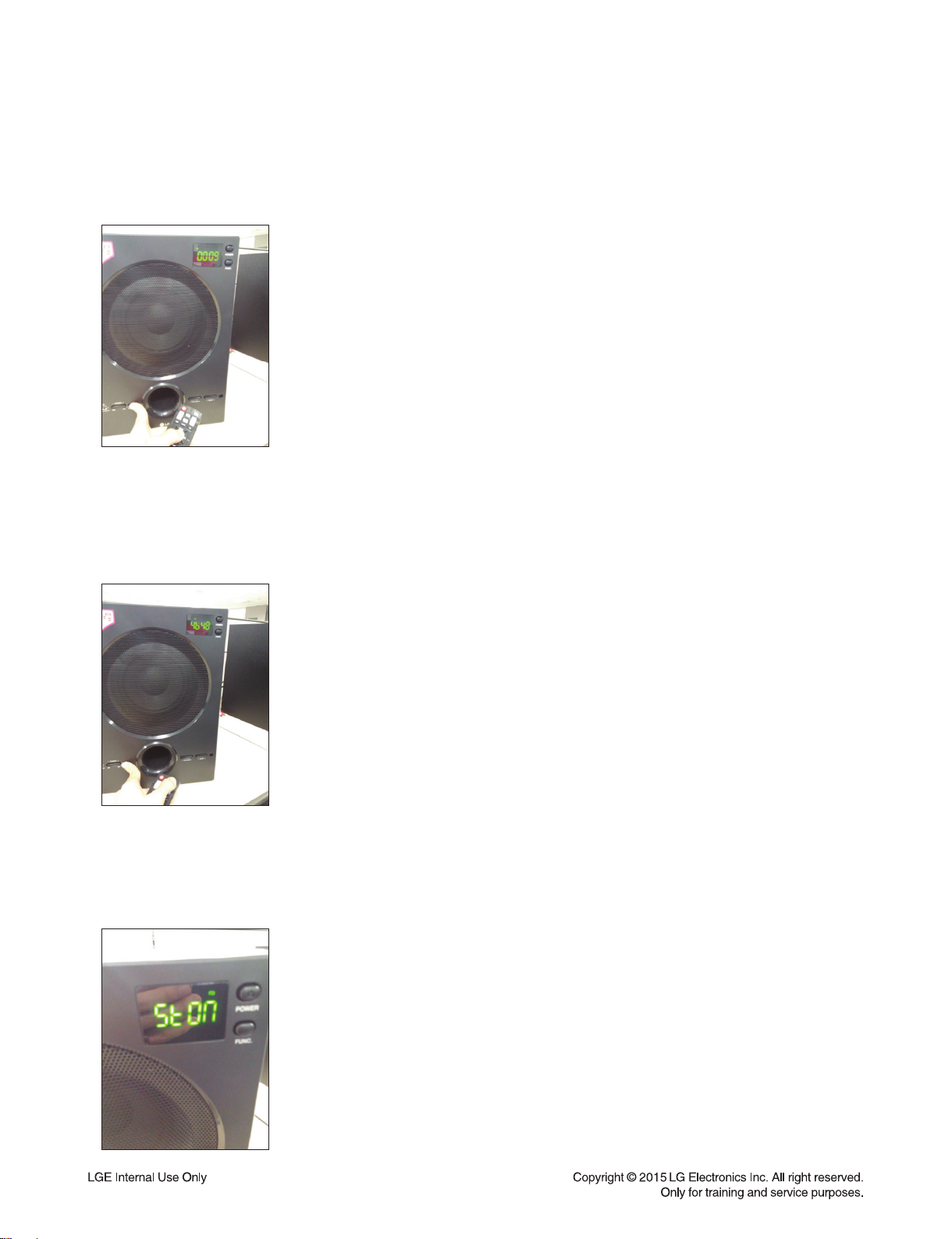
HIDDEN KEY MODE
1. Software Version
After Power On, Press Woofer front Play/Pause button + RCU Play/Pause button during 5seconds.
Then, you can see the SW version on LED display.
(Ex. “00 09”)
2. Factory Reset
After Power On, Press Woofer front Play/Pause button + RCU FUNC button during 5seconds.
Then, Factory reset will be executed and
you can see the Checksum of SW version on LED display. (Ex. “46 48”) Finally,
it will be turned off automatically.
3. FM Stereo On/Off
At FM mode, Press Woofer front Play/Pause button or RCU Play/Pause button shortly.
Then, you can see the changed state of stereo on LED display.
(Ex. “St On”)
1-4
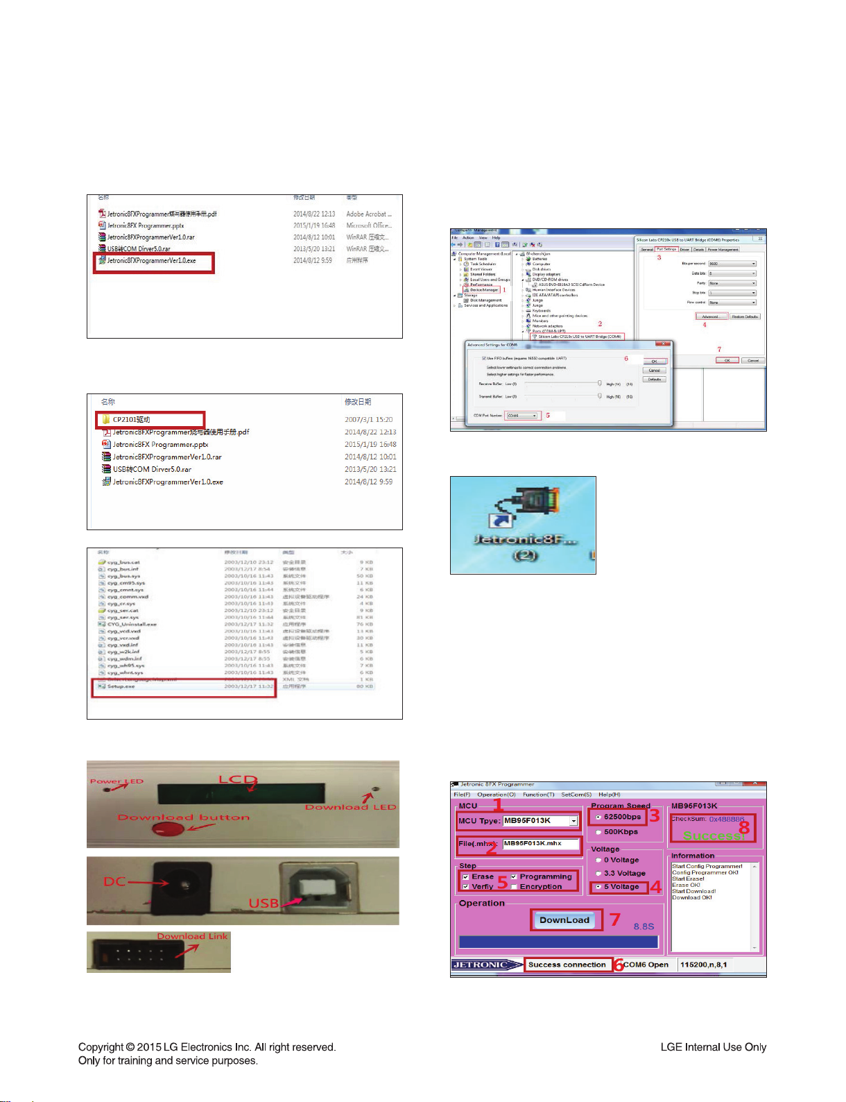
THE PROCESS OF UPDATING SOFTWARE
1. Upgrade MCU software
1-1. Install Update Program on PC.
1) Execute Jetronic8FXProgrammerVer1.0.exe fi le.
2) Install USB to COM Driver.
- Execute Setup.exe fi le.
1-3.
Power on the Jetronic8FX, and Connect to PC.
Make sure the driver is installed and COM is available. Generally, COM port number is less than 10.
Select an available COM which is not in use.
1-4. Execute Jetronic8FX programmer.
1-2. Download device interface description.
1-5. Download updating software to programming
device.
1. MCU Type: MB95F013K
2. “File” “Open File”, choose download
x.mhx fi le (Example: MB95F013K.mhx)
3. Baud rate: 62500bps
4. Voltage: default 5 V
5. Step: default
6. Device to connect the PC OK!
7. “Download”: down fi le to device.
8. Success!
1-5
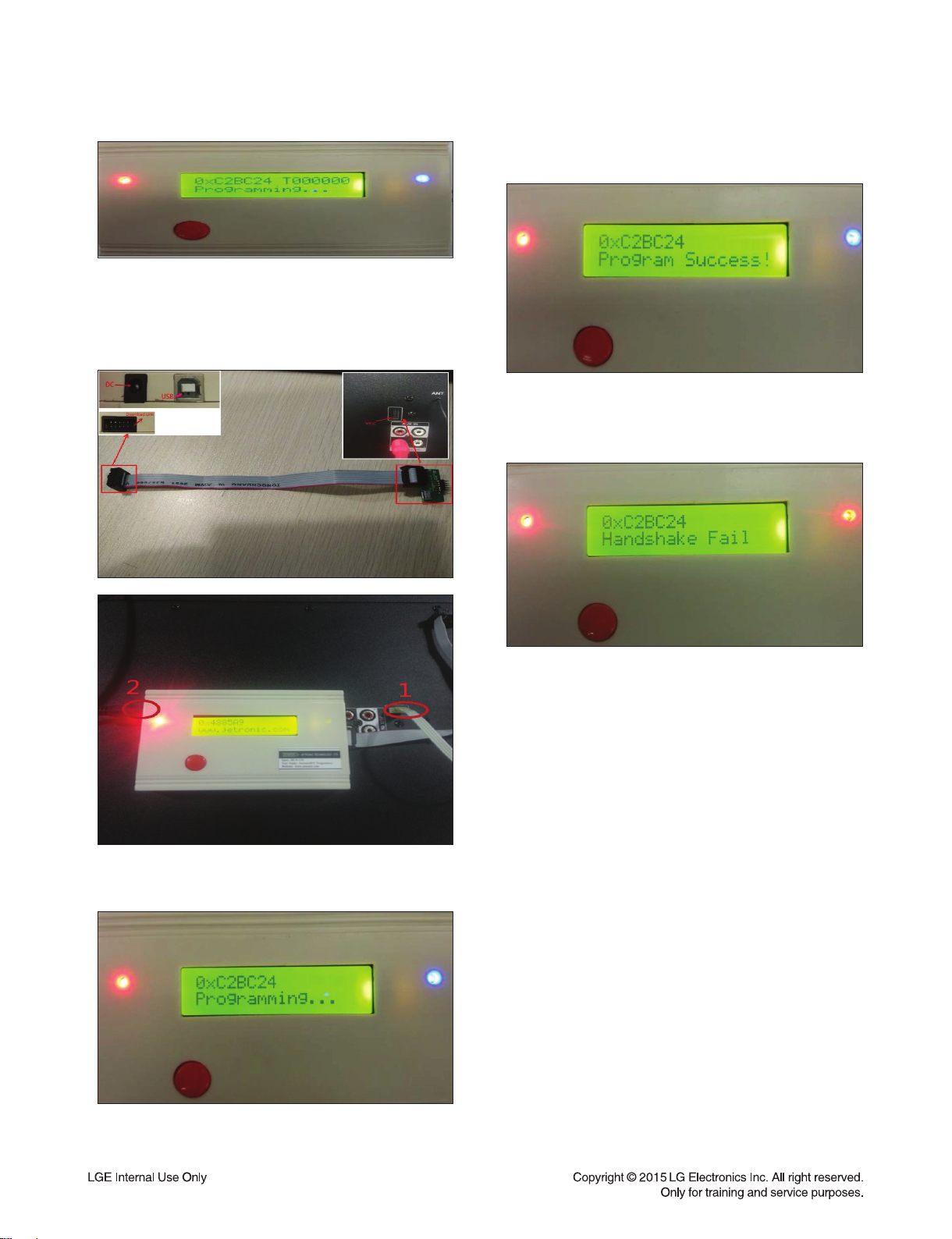
1-6. Download updating software to LH70A.
1) Connect programming device to LH70A.
2) Power ON programming device.
3) LH70A without access to electricity.
5) The LCD shows program success and blue light
is normally on.
1-7. If blue light turns red and buzzer "di" three
times and the LCD shows handshake fail,
burning is failed. Then repeat step 1-6.
4) Press the download button.
The LCD shows programming and blue light fl icker.
1-8. If updating is successful and another speaker
needs update, then repeat step 1-6.
1-6

2. Upgrade USB software
2-1. Install Update Program on PC.
1)
Execute Setup.exe fi le in ProductTool_V5.42 folder.
2) Identify connected USB port at fi rst time.
3) Select SW update fi le with "..." button.
2-2. Plug out Power Cord and connect LH70A
to PC via USB cable.
2-3. Using Update Program, do SW update.
1) execute Mass Product Tool.
4) Replace SW update fi le in Update Program.
1-7
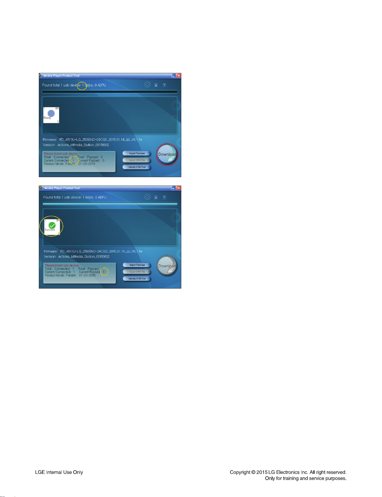
5) Check USB device connected
and click DOWNLOAD button.
1-8

3. Upgrade Bluetooth software (Optional Part)
3-1. Install Update Program on PC.
1) Execute InstallBlueSuite_2_5_8_667.exe fi le
3-2. Insert PCB correctly.
3-5. Enter DFU mode.
BT mode & Press TUNING- until “dFU” display on
LED.
3-6. PC will install the driver automatically.
3-3. Connect LH70A to PC via USB cable.
3-4. Enter factory test mode.
USB mode & no USB & Press TUNING- and
TUNING+ during 5 seconds.
3-7. Using Update Program, do SW update.
1) Execute PSTool.
1-9
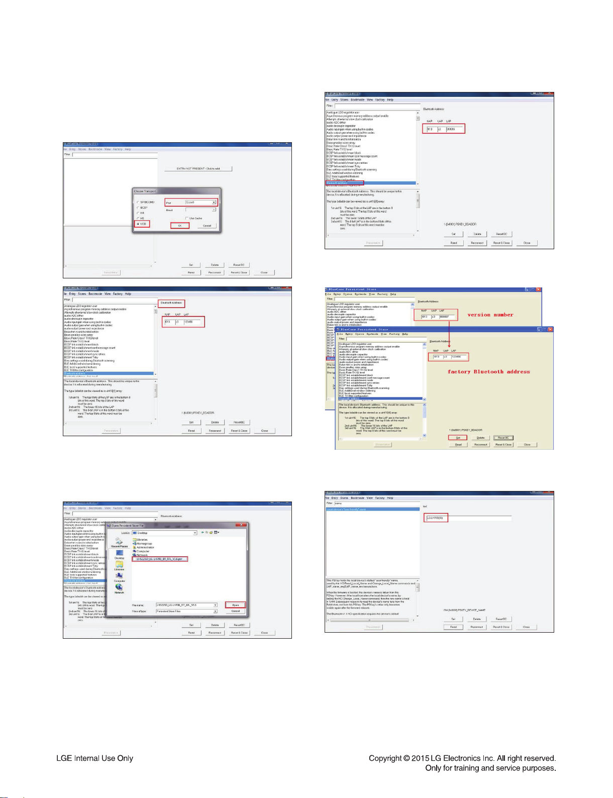
3-8. Choose USB. There is \\.\csr0 in port if
successful. Then we can read Bluetooth
address and record it. We must restore it after
device upgraded.
3-10. Restore Bluetooth Address.
3-9. Choose File Merge in turn. Select SW
update fi le with "Open" button. We can read
Bluetooth Address which matches the latest
MCU version number.
3-11. Restore Bluetooth Name.
- Enter “name” in Filter and modify Bluetooth name.
3-12. Power off to exit the DFU mode.
1-10

SPECIFICATIONS
Auto power down
This unit will turn itself off to save electricity in the case were the main unit is not connected to an external
device and is not used for 20 minutes.
The unit will also turn itself off after six hours if the Main unit has been connected to another device using the
analog inputs.
Product type 2,1 speaker system
Power Supply 110 -240 V ~ 50 Hz/60 Hz
Power Consumption 20 W
Dimensions (W x H x D) Satellite: Approx. 110 (W) mm x 201 (H) mm x 115 (D) mm
Subwoofer: 264 (W) mm x 370 (H) mm x 323 (D) mm
Net Weight Main Set : Approx. 5.44 kg
Speaker (1EA) : Approx. 0.64 kg
Operating Temperature 0 °C to 35 °C
Connectivity 3,5mm stereo jack-male input jack
Tuner FM Tuning Range : 87.5 to 108.0 MHz or 87.50 to 108.00 MHz
Impedance Subwoofer: 6 (Ω)
Satellite: 8 (Ω)
Frequency response Subwoofer: 55 Hz ~ 104 Hz
Satellite: 40 Hz ≤ 20 kHz
Total Max. power 70 W (THD : 10 %)
Signal to noise ratio 75 dB
• Design and specifications are subject to change without notice.
1-11

1-12

SECTION 2
CABINET & MAIN CHASSIS
CONTENTS
EXPLODED VIEWS ........................................................................................................................................... 2-3
1. SUBWOOFER SECTION .......................................................................................................................... 2-3
2. SPEAKER SECTION ................................................................................................................................ 2-5
3. PACKING ACCESSORY SECTION ......................................................................................................... 2-7
2-1
2-2
A40
300
MAIN
SMPS
FM
261
512
512
512
511
513
260
A47
507
CABLE1
A46
A45
825
B
A
B
A
C
C
D
E
F
D
E
F
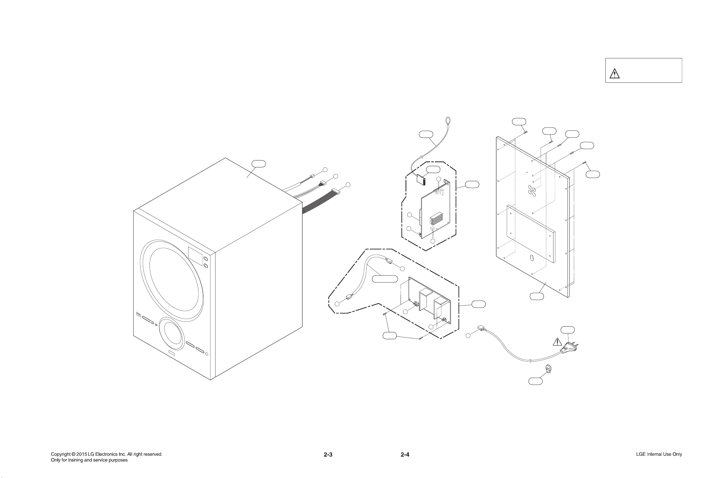
EXPLODED VIEWS
1. SUBWOOFER SECTION
NOTES) THE EXCLAMATION POINT WITHIN AN
EQUILATERAL TRIANGLE IS INTENDED
TO ALERT THE SERVICE PERSONNEL
TO THE PRESENCE OF IMPORTANT
SAFETY INFORMATION IN SERVICE
LITERATURE.
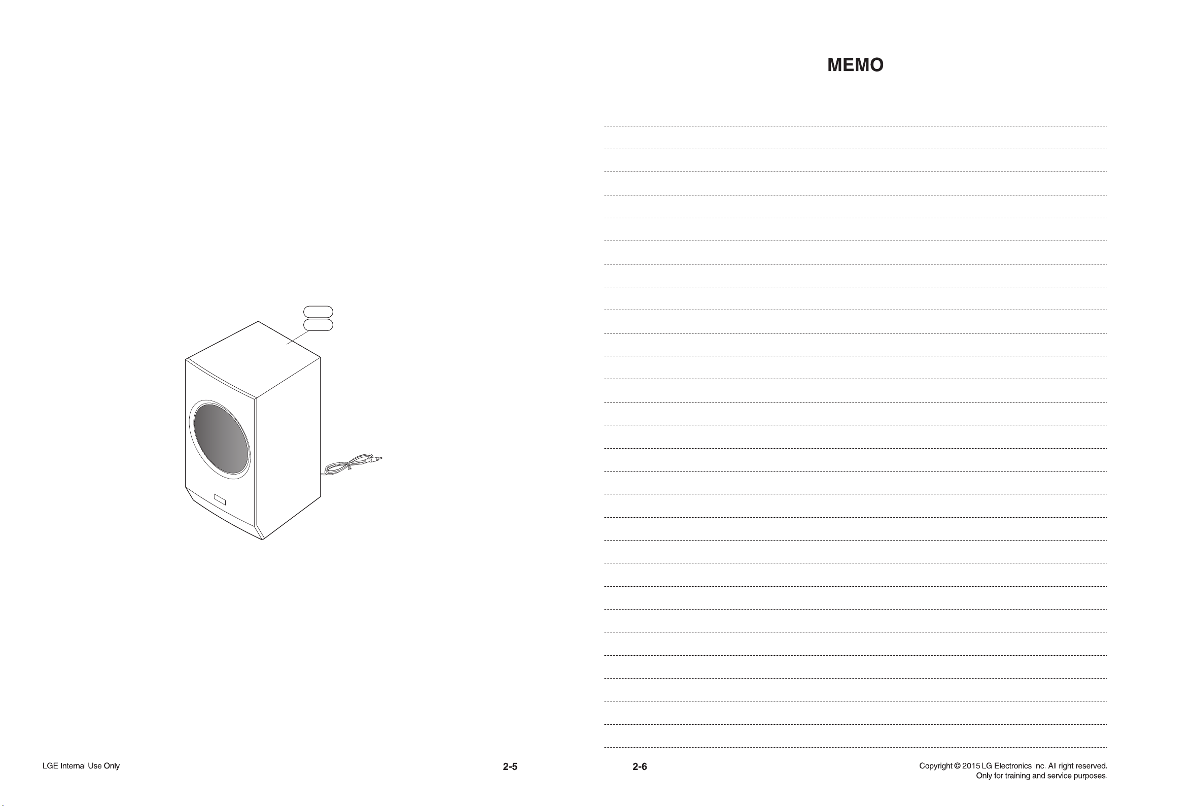
2. SPEAKER SECTION
A60L (RCA: White)
A60R (RCA: Red)
 Loading...