

Page 1
The Difference
Is in the Detail
With LG, it’s all possible
AC Module System Installation Instructions
LGxxxA1C-B3 / LGENBOX-01
* A minimum slope of 5 in/ft. for roof installations is required to meet fire class ratings.
The array frame must be grounded in accordance with NEC Article 250.
Page 2

2
Table of Contents
1 Safety 3
1-1 Safety Symbols 3
1-2 Important Safety Instructions 3
1-3 FCC Guidelines 4
1-3 Circuit Symbols 4
2 Introduction 5
3 AC Module 6
3-1 Before Installation 6
3-2 Inspecting the Area of Installation 6
3-3 Inspecting Components of the AC Module 7
3-4 Measuring AC Voltage of the Utility 7
3-5 Wiring Diagram of AC Module System 8
3-6 Installing the AC Junction Box and PV Rack 9
3-7 Mounting the AC Module 9
3-8 Connecting AC Modules (Trunk Cable) 12
3-9 Grounding 16
3-10 Connecting AC Module Array to Distribution Panel
(General AC Cable, Transition Cable) –240VAC, 208VAC 18
3-11 Operation 22
3-12 Maintenance 22
4 EnerBox
4-1 Checking Components of the Communication Gateway 23
4-2 Connecting the Communication Gateway 24
4-3 Configuring the Installation App 25
4-4 Website 28
5 Accessories 29
6 Product Specifications 30
6-1 AC Module 30
6-2 EnerBox 32
6-3 Response to Abnormal Conditions 33
6-4 Dedicated Cables 34
7 Warranty 35
8 Transportation and Storage 35
9 Contact 35
TM
Communication Gateway 23
Revisions
Date Version Description of Change Remark
6/30/2014 1.0 (1
st
Edition)
Page 3
3
1 Safety
Note and comply with the safety guidelines of this manual while handling AC modules. Failure to comply may result
in severe damage to the equipment and/or fatal injuries.
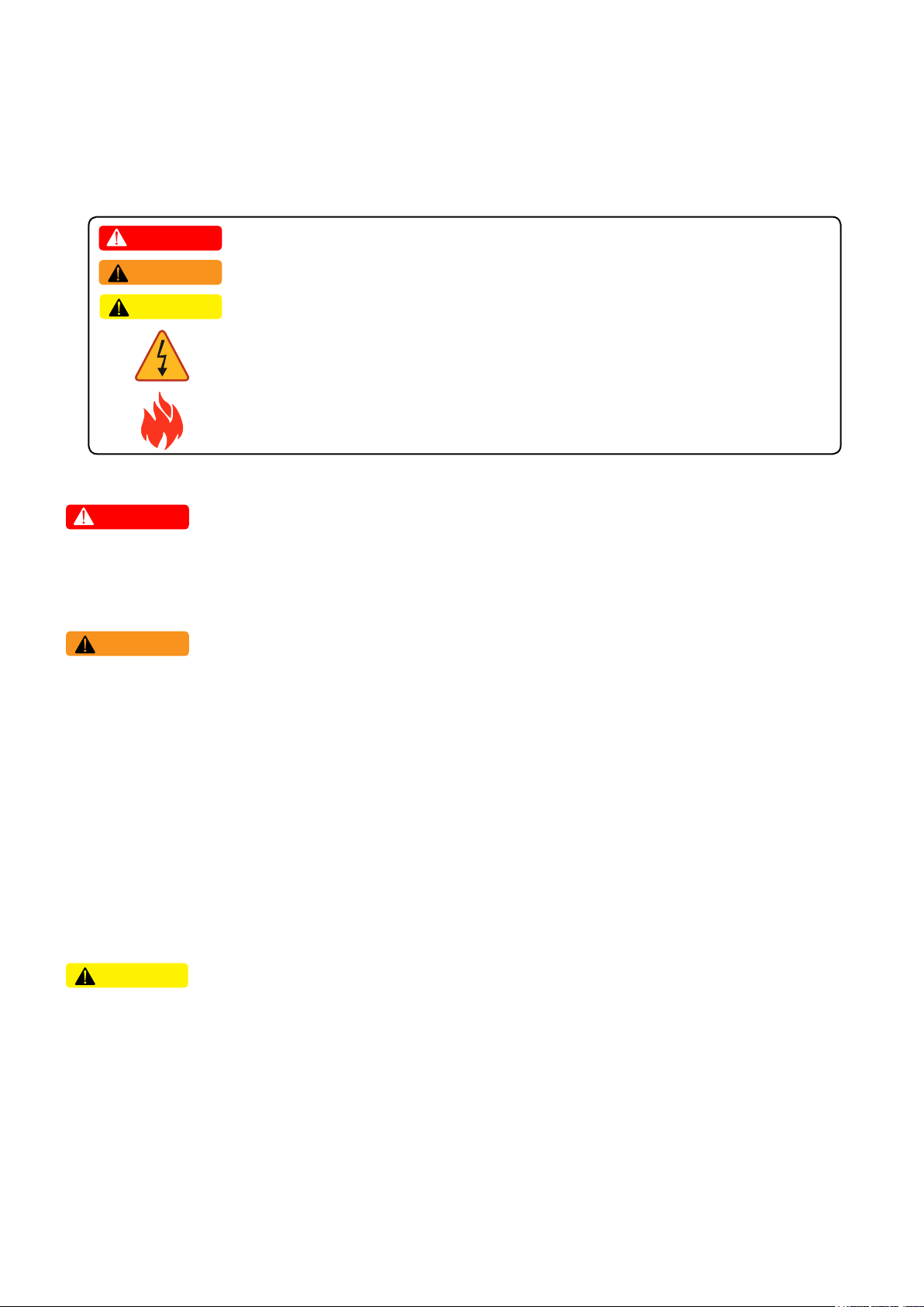
1-1 Safety Symbols
Safety symbols are used to minimize loss and injury during handling and operation of the equipment specified in this
manual.
DANGER
WARNING
CAUTION
Failure to comply with the instructions may cause fatal injuries or immediate death.
Failure to comply with the instructions may cause severe injuries or death.
Failure to comply with the instructions may cause injuries or damage to property.
Failure to comply with the instructions may cause severe injuries or immediate death
by overvoltage.
Failure to comply with the instructions may cause injuries or damage to property by fire.
1-2 Important Safety Instructions
DANGER
• To prevent the risk of electric shock, stay away from current-carrying terminals during operation. And, allow
several minutes after the circuit breaker has been turned off. It may be energized in the open position.
• To prevent the risk of overvoltage, do not disconnect the cable connector during operation.
WARNING
• To prevent the risk of burns, do not touch metal parts during operation.
• For safety, only qualified persons should service modules.
• To prevent the risk of electric shock, stay away from damaged module(s). Do not use module(s) with broken glass
or torn backsheets.
• Damaged modules must be handled with proper safety equipment. Failure to comply may result in serious bodily
injury or death.
• Micro inverter warranty void if cover removed. No serviceable parts inside. Refer servicing to qualified personnel.
• For proper operation, make sure to use exclusively cables, connectors and accessories provided by LG Electronics.
Parts that are not listed may cause critical danger.
• For proper operation, the AC module shall be connected only to a dedicated branch circuit.
• To prevent the risk of fire, do not connect any device between the AC module and circuit breaker. Circuit breaker
may not work properly.
• Before installation, make sure to check that the area of location meets the required environment specified in
Chapter 6. Product Specification (Voltage, frequency, temperature, number of AC modules, overcurrent device).
CAUTION
• Use proper equipment, connectors, wires and buttresses for the installation of the module. Failure to comply may
result in product damage, product failure and/or bodily injury.
• To reduce the risk of accidents, do not install during inclement weather.
• To prevent the risk of electric shock, do not touch the glass surface or frame of the solar module after installation.
• To prevent the risk of injury, do not apply pressure on the module (ex. placing heavy objects or stepping on the
module).
• To prevent the risk of injury, do not drop the module; modules must be gently handled and placed down.
• For proper operation, do not scratch the coating surface of the frame. It may increase the corrosion of the frame.
• For proper operation, do not concentrate sunlight on the module surface.
• Addition of holes in the frame or glass of the module may decrease the strength and integrity of the frame or glass.
• Do not remove warning labels.
• Store the module in its original package until installation.
Page 4
4
1-3 FCC Guidelines
For Micro inverter & Communication Gateway
You are cautioned that changes or modifications to this unit not expressly approved by the party responsible for
compliance could void the user’s authority to operate this equipment.
This equipment has been tested and found to comply with the limits for a Class B Digital Device, pursuant to Part
15 of the FCC Rules. These limits are designed Part 15 of the FCC Rules. These limits are designed to provide
reasonable protection against harmful interference in a residential installation. This equipment generates, uses and
can radiate radio frequency energy and, if not installed and used in accordance with the instruction, may cause
harmful interference to radio communication. However, there is no guarantee that interference will not occur in a
particular installation. If this equipment does cause harmful interference to radio or television reception, which can
be determined by turning the equipment off and on, the user is encouraged to try to correct the interference by one
or more of the following measures:
- Reorient or relocate the receiving antenna.
- Increase the separation between the equipment and receiver.
- Connect the equipment into an outlet on a circuit different from that to which the receiver is connected.
- Consult the dealer or an experienced radio/TV technician for help.
This device complies with part 15 of the FCC rules. Operation is subject to the following two conditions:(1) This
device may not cause harmful interference, and (2) This device must accept any interference received, including
interference that may cause undesired operation.
For Communication Gateway
Indoor use only
FCC Caution: For indoor use only; outdoor use or in any other environments not covered in this manual may
violate the FCC regulation and void the user’s authority to use the product.
Specially, within the 5.15-5.25 GHz band, U-NII device is restricted to indoor operations to reduce any potential for
harmful interference to co-channel MSS operations.
FCC RF Radiation Exposure Statement:
This equipment complies with FCC radiation exposure limits set forth for an uncontrolled environment.
This equipment should be installed and operated with a minimum distance of 8.87 inches (20 cm) between the
radiator and your body. End users must follow the specific operating instructions for satisfying RF exposure
compliance. This transmitter must not be co-located or operating in conjunction with any other antenna or
transmitter.
CAUTION: Regulations of the FCC and FAA prohibit airborne operation of radio-frequency wireless devices
because their signals could interfere with critical aircraft instruments.
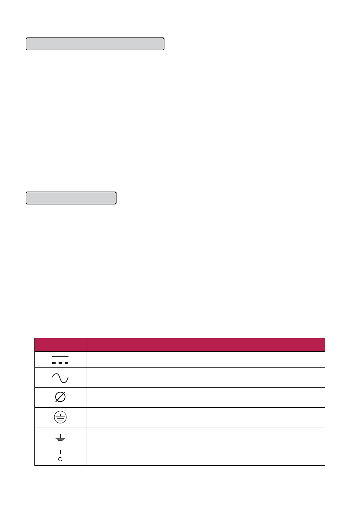
1-4 Circuit Symbols
The following circuit symbols are used to describe the AC module circuit in this manual.
Circuit Symbol Description
DC (Direct Current) supply. Generated from PV module.
AC (Alternating Current) supply. Generated from utility and micro inverter. Used in
electric appliances.
Represents the phase of AC. The number in front of this symbol represents the
number of phases.
Terminal for EGC (Equipment Grounding Conductor) normally used to connect non–
current carrying metal parts of equipment together.
Terminal for GEC (Grounding Electrode Conductor) connecting EGCs and neutral
conductors to the ground for grounding.
Circuit breaker switch. l : ON, O : OFF.
/ PV module: Equipment that receives solar energy and generates DC power.
/ Inverter: Equipment that converts DC power into AC power.
/ Utility-Interactive inverter: Inverter connected in parallel with the grid to supply power.
/ Micro inverter: Inverter designed with minimal size to supply power to each PV module.
Page 5
5
2 Introduction
LG AC module consists of PV(Photovoltaic) module and “Utility-Interactive” micro inverter. Without any additional
equipment, it converts the solar energy to AC power used in electric appliances and supplies to the utility.
The Advantages of AC Module System
• The AC module system, unlike a central inverter system, operates with module MPPT. The AC module does not
have any adverse effect on the other modules, allowing more power production in comparison to a central
inverter system.
• Eliminates installations related to DC voltage, reducing total installation and labor costs.
• Maintenance is easy as the system can be monitored in real time.
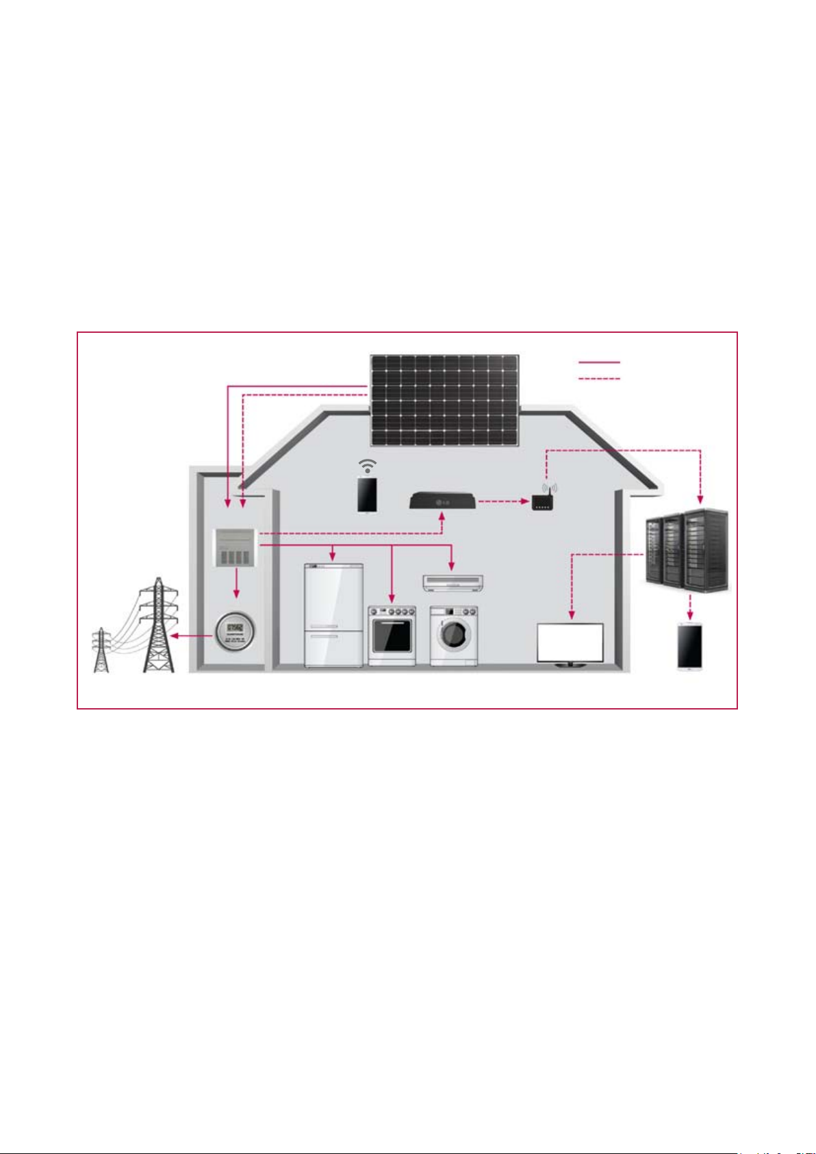
AC Module System
1. AC Module
Power
Communication
2. Communication
Gateway
Gird
Distribution
board
Meter
Smartphone
(Installation
App)
1. AC module
- Consists of PV module and micro inverter.
- Performs MPPT function, maximizing power generation.
2. Communication gateway
- Collects information about AC module system via AC cable.
- Stores data inside.
- Uses wireless connection to transmit data to smartphone or tablet.
Server
Router
3. Monitoring
PC
Smartphone
3. Monitoring
- Monitors and analyzes condition of the solar system.
- Transmits the condition of the system to the service center in case of a problem.
/ MPPT : Maximum Power Point Tracking.
Page 6

6
3 AC Module
3-1 Before Installation
• LG AC module is “Utility-Interactive”, which requires approval from the corresponding authority prior to system
connection. Contact the applicable local government agencies and/or utility company.
• Installation, maintenance, and supervision may only be carried out by an approved installer for the safety of
workers and systems.
• Read and follow the installation guidelines specified in this manual. Installation in unapproved methods may
result in injuries includes fatal injuries and/or damage to the equipment. Consult with LG Solar for the approval of
the installation methods that are not specified in the installation manual. Failure to comply will void the warranty
and the module certificate.
• After receipt of LG AC module, check for possible damages from production or transportation. Any damaged
module must not be installed. Request an exchange by contacting LG Solar.
• If original modules (or parts) are replaced, check that the modified module works properly. The modified module
shall retain its model number.
• Store the AC module in its original packing until installation.
• Do not remove the dust cover from the connector in advance. Any particles in the cable may cause interference
to the current.
• Consider the weight of LG AC module before installation. The weight of LG AC module is 39.68lbs.
• Do not work alone. Install as a team unit with at least 2 persons working at a time.
• To prevent the risk of accidents, install with safety gear on at all times.
• Do not install in times of inclement weather. There is a risk of electric shock when it is raining or snowing.
• If installation location is high above ground, make sure to wear safety belt during the installation.
• Check that all parts used during the installation are certified for outdoor usage.
• During the module installation, do not let children near the module and the system.
• Carry out the installation according to the local electric code.
3-2 Inspecting the Area of Installation
Check that the location of installation meets the following requirements.
• Do not install near highly combustible structures or materials.
• Do not install where the maximum ambient temperature exceeds 149℉ (65°C).
• Do not install at a place with direct exposure to salt water or ammonia.
• Do not install at a place easily accessible to people.
• Do not install indoors or on a moving vehicle.
• In a place with frequent lightning storms, by installer, an auxiliary grounding may be connected directly from the
AC module system to the ground.
• If the target installation structure lies on an unleveled surface, do not forcefully modify the module to fit the
structure. Make sure that the installation structure has been set up to provide a flat surface. Unreliable structures
may cause damage to the product during and/or after installation.
Page 7
7
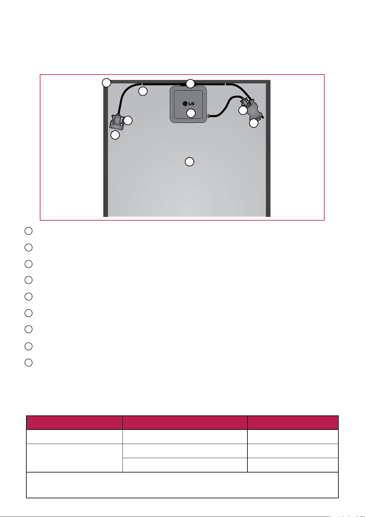
3-3 Inspecting Components of the AC Module
After receiving the product, inspect all parts for possible deformity or malfunction.
3
7
9
2
6
8
1
1 PV module
Converts the solar energy to DC power.
2 Micro inverter
Converts DC power generated by each PV module to AC power.
3 PV frame
Protects and fixates AC module.
4 AC drop cable
Connects a micro inverter to trunk cable.
5 Trunk male connector
Junction connector between AC drop cable and trunk female connector.
6 Trunk female connector
Connects to trunk male connector of the next AC module in the array.
7 Bracket
Fixes trunk cable onto PV frame.
8 Dust cover
Prevents entry of foreign particles.
9 Cable holder
Prevents AC trunk cables from moving during transportation.
※ Warranty is void if it is broken after installed.
4
5
3-4 Measuring AC Voltage of the Utility
Measure the AC voltage of the utility at the distribution panel using a multi-meter. Refer to the table below to
determine the number of modules per array.
AC Voltage
Single phase 240V (per 1-array)
Three phase 208V
(per 3-array)
* For details, refer to Chapter 3-10. Connecting AC Module Array to the Distribution Panel.
* Factory setting of AC voltage of the AC modules is 240VAC. If you want to change the operating AC voltage range, you
need to set grid configuration directly. For details, refer to Chapter 4-3. Configuring the Installation App - Step 5.
Number of Maximum AC Modules
12 units
6 units ⅹ 3 (merge type)
11units ⅹ 3 (split type)
20A Circuit Breaker
2-pole ⅹ 1ea
3-pole ⅹ 1ea
2-pole ⅹ 3ea
Page 8
8
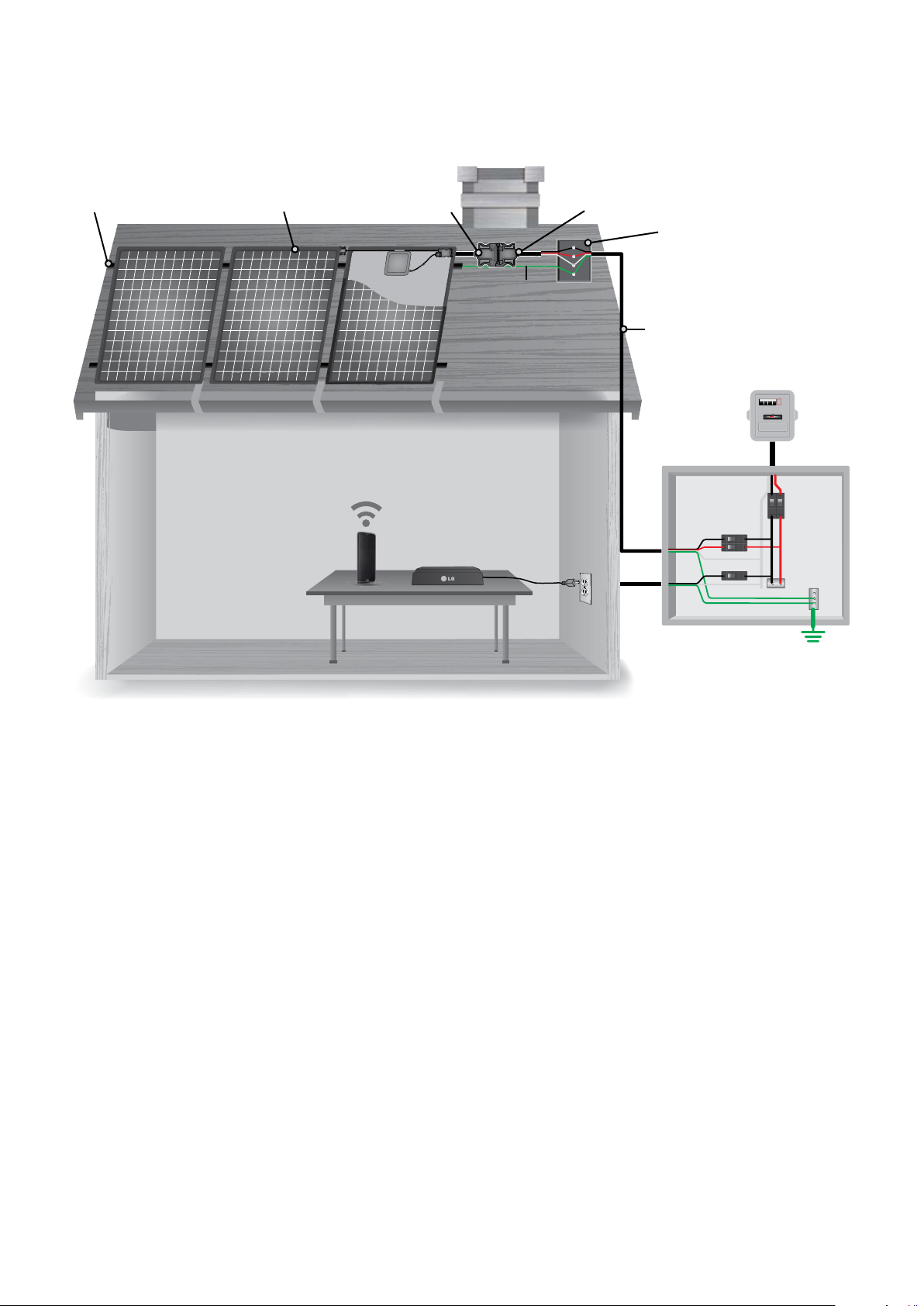
3-5 Wiring Diagram of AC Module System
00000
NL1L2
G
Below is a sample diagram of the AC module system.
PV Rack AC Module Trunk Cable Transition Cable
Equipment
Grounding
Conductor
AC Junction Box
General AC
Cable
Meter
Installation App
Communication
Gateway
120VAC
Install in the following order. For details, please refer to each chapter.
Chapter 3-6. Installing the AC Junction Box and PV Rack
Install the AC junction box and PV rack at the installation site.
Chapter 3-7. Mounting the AC module
Mount AC modules on PV rack.
Chapter 3-8. Connecting AC Module (Trunk Cable)
Connect to AC modules by using trunk cables.
Chapter 3-9. Grounding
Connect the equipment grounding conductor to the distribution panel.
Distribution Panel
Chapter 3-10. Connecting Array of AC Modules-to-Distribution Panel (General AC Cable, Transition Cable) -
240VAC, 208VAC
Connect arrays of AC modules to the distribution panel by using transition cables and general AC
cables. (Wiring method depends on the voltage of the utility)
Chapter 4-2. Connecting the Communication Gateway
Connect the communication gateway to 120VAC outlet.
/ PV Rack: Structure used to fix AC modules on surfaces like roofs, empty plots, etc.
/ AC Junction Box: Container for electrical connections of AC cables, usually intended to conceal them from sight and prevent tampering.
/ General AC Cable : AC cable, not supplied by LG, used generally for outdoor electrical installation.
/ Distribution Panel : Component of an electricity supply system which divides an electrical power feed into subsidiary circuits in a common
enclosure that provides a protective fuse or circuit breaker for each circuit.
Page 9
9
3-6 Installing the AC Junction Box and PV Rack
Before installing the AC junction box and PV rack, be aware of the following requirements:
NOTICE
• To allow ventilation through the backside of the AC module, it is recommended to install the PV rack allowing a
gap of at least 4 inches (100mm) between the back of the module and roof surface.
• Install AC junction box near the AC module.
• Install using the parts approved by the relevant local authority of installation site.
• Select appropriate angle for maximum exposure to sunlight.
Construct the over all frame of the solar system in the following order:
1. Install the PV rack according to the number of modules per array and the dimensions of the AC module. (refer to
Chapter 6. Product Specification)
2. Install the AC junction box near the PV rack. Select the size and type of AC junction box suitable for connection
type according to the output voltage. (Refer to Chapter 3-10. Connecting Array of AC Modules to Distribution
Panel)
3-7 Mounting the AC module
Before mounting AC module in the PV rack, be aware of the following requirements:
NOTICE
• Check that all parts of the product are intact and operational.
• Check that the cable connectors are well fixed.
• It is recommended to install the module at any angle with respect to the horizon, making it easier for dust to be
washed off by rain.
• When installed on a roof, the PV module must be mounted over a fire-resistant roof. The fire resistance of the PV
module is class C according to ANSI/UL790.
• For proper operation, do not remove PV frame or replace with another frame.
• Additional holes on the frame may weaken, the strength of the frame and cause damage.
• To avoid the tensile strain from the thermal expansion, it is recommended to install with a gap of between 0.236
inches (6mm) to 7.087 inches (180mm) between PV frames considering the length of the trunk cable. If gap
exceeds 7.087 inches, use the extension cable.
• Mount LG AC module to PV rack with 8~12N-mtorque.
• For reliable connection, do not place any foreign objects between PV frame and the PV rack.
• When installing modules in areas of heavy snow, special care should be taken to install the modules in a manner
that provides sufficient strength while meeting local code requirements.
PV Module Specification (conditions of 1000W/m2 irradiance and 77ºF (25°C) solar cell temperature)
Operation temperature
Maximum operation temperature: +194°F (90°C).
Minimum operation temperature: -40°F (-40°C).
Design strength
LGE solar modules are certified to basic loads of 50lb/ft
(about 2400 Pa)
Notes
- LG AC module can not be operated in locations of direct contact to salt water or ammonia.
- LG AC module is thin, so it may bend depending on the type of the PV rack.
- Reflection from snow, water or other weatherly variables may increase the output generated in the module.
- Colder temperatures may substantially increase voltage and power.
2
.
Page 10
10
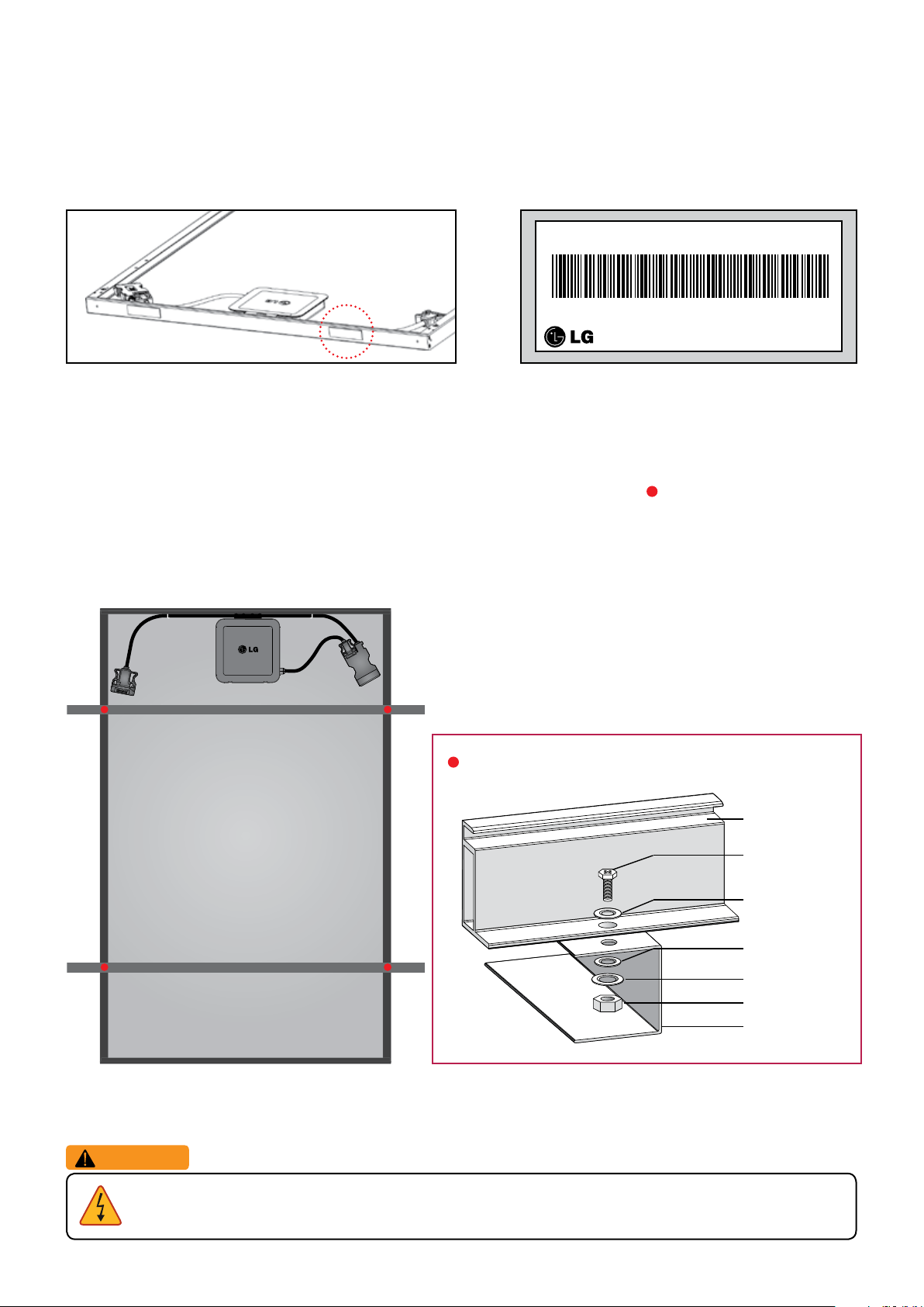
Fix AC module to the PV rack in the following order:
Serial No. K2xxxxxxxxxx
MAC Address : 48:D1:8E:40:00:90
Made in Korea
Step1. Peel adhesive label attached on the side of PV frame of AC modules and stick on a piece of paper mirroring
the array to map for monitoring.
Step 2. Place AC modules on the PV rack with a minimum gap of 0.236 inch (6mm) between each module. To
prevent the risk of slipping during installation, mount AC modules one by one. Connect trunk cables to each
mounted AC module. (Refer to Chapter 3-8. Connecting AC Modules)
Step 3. Fixate the PV module to the PV rack on the four mounting holes (marked by points below) with 4 M6
stainless bolts, 4 nuts, 4 spring washers, and 8 flat washers.
(To mount according to the different type of PV racks, refer to the next page under Mounting According to
the Different PV Racks)
WARNING
• To prevent the danger of the electric shock, make sure to turn off the circuit breaker prior to installation.
Connecting the PV Rack and PV Module
Module frame
Bolt
Flat washer
Flat washer
Spring washer
Nut
Support
Page 11
11
1 2 12
1 2 12
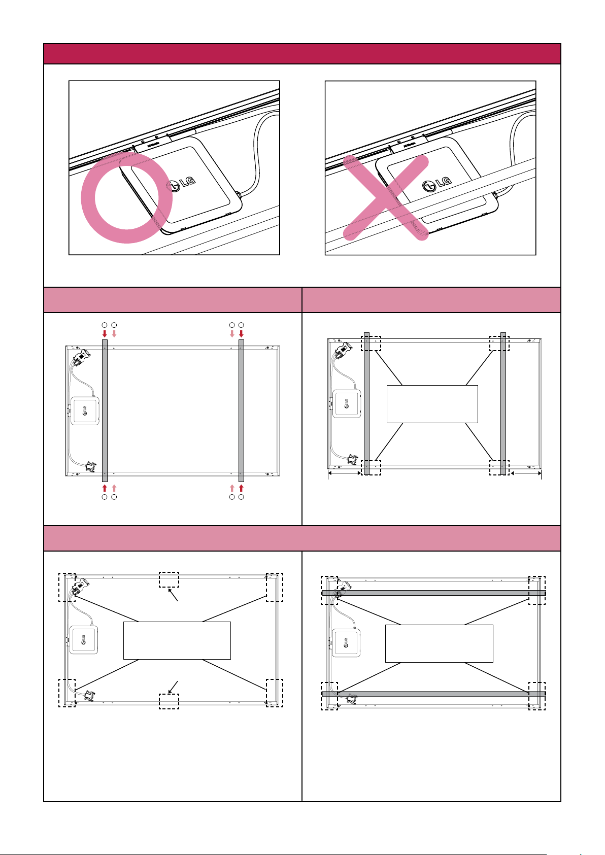
Mounting According to the Type of PV rack
1 2 12
Minimum distance between module edge to PV rack is 10.236 inch (260mm).
Mounting Type Clamping Type (Long Side)
Use four mounting holes on two opposite sides.
Center ± 3.937 inch (100mm)
Clamping Range:
From module Edge
to 10.630 inch (270mm)
Center ± 3.937 inch (100mm)
11.811 inch
(300mm)
Use four clamps on the long frame.
Clamping Type (Short Side)
This method is not tested by IEC/UL.
Clamping Range
7.874 inch (200mm)
11.811 inch
(300mm)
Clamping Range:
From module Edge to
4.724 inch (120mm)
This installation is allowed in the following cases:
Use four clamps on the short frame and two
1. Slope roof: If module is installed parallel to the
clamps at the center of long frame.
2. Flat roof: If installed with an additional stand
※ Please check that PV rack does not interfere with a micro inverter.
Use four clamps on the short frame.
rooftop.
such as wind shield or deflector.
Page 12

12
3-8 Connecting AC Modules (Trunk Cable)
Before connecting AC modules in each array, be aware of the following precautions:
Trunk connector insertion
- Insert trunk female connector into trunk male connector in horizontal direction. If you insert at wrong angle, the
connector can be damaged.
- Insert fully into the end of the connector until you hear a click.
Trunk connector removal
- Use the dedicated unlocking tool to remove the connector. Do not use any other tools.
Checking Accessory
Trunk cable
connector
Unlocking tool
Trunk cable usage and maintenance
- Do not bend the cable more than 10 times. It may
result in mechanical and/or electrical problems.
- Do not let cable be pulled too tight or hang too loose. Internal conductor may break.
- Do not allow any liquid inside to prevent danger of electric shock.
- Do not use damaged cables.
- Do not cut or transform the dedicated cables for use.
- Frequent disassembly or connection may damage the cable.
- The size of dedicated cables are decided by NEC2014. (For the size, refer to Chapter 6. Product Specification)
- For information about accessory, refer to Chapter 5. Accessory.
- Avoid all external interference to the connector. Do
not impose force on the side direction of the
connector.
Drop cable
connector
- For easy cable connection, the trunk male connector is detachable from the back sheet of PV module.
Page 13

13
To prevent dust from collecting, connect each AC module one by one in the following order:
Step 1. Take the female connector out from the cable holder on the PV frame.
(Do not take the unused connector out of the last AC module to prevent sagging.)
Step 2. Remove the dust cover of the trunk female connector of the module you want to install and trunk male
connector of next one.
Step 3. Insert the trunk female connector into the trunk male connector in the illustrated direction below until you
hear a clicking sound to connect all AC modules of each array.
WARNING
• Make sure to use only dedicated cable connectors provided by LG. Non-genuine connector may not be
waterproof and/or non-genuine cable may limit the current flowing inside.
• To prevent the danger of the electric shock, firmly connect all connectors and endcaps.
Page 14

14
Step 4. To connect AC modules in different rows, use the extension cable.
(Refer to the next page under Cable Usages According to AC Junction Box Locations)
Checking the Accessories
Female + Female
extension cable
Step 5. Remove the dust cover of the female connector of the last AC module and seal with end cap to ensure
waterproofing and dust prevention. Insert the end cap into the trunk male connector in the arrow direction
until you hear a clicking sound. Seal the end part by referring to the following drawing.
If trunk female
connector is the end part
‹
Male + Male
extension cable
Female + Male
extension cable
‹
If trunk male
connector is the end part
Checking Accessory
Male end cap Female end cap
Step 6. Check the cables to verify they have not been pulled too tight or are hanging too loose. If necessary, fixate
them using the cable fixing holes on PV module frame with fixing holders, such as cable ties, so that the
cables do not touch the ground.
Trunk connector and end cap serve to prevent collection of dust and waterproof functions.
Page 15

15
Cable Usages According to AC Junction Box Locations
If first AC module connected to AC junction box is on the top left side
Use male transition cable for connection between array and AC junction box.
Seal the trunk male connector of the last AC module using a female endcap.
Male transition
cable
* First AC
module
Female + Female
extension cable
[Female end cap]
Male + Male
extension cable
Female
end cap
* Last AC
Female + Male
extension cable
module
If first AC module connected to AC junction box is on the top right side
Use female transition cable for connection between array and AC junction box.
Seal the trunk female connector of the last AC module using male endcap.
Female transition
cable
* First AC
Male + Male
extension cable
module
Female +
Female
extension
cable
[Male + Male extension cable]
[Female + Female extension cable]
[Female + Male extension cable]
[Male end cap]
[Male + Male extension cable]
Male end cap
* Last AC
module
Female + Male
extension cable
If AC module is installed in landscape mode
Place AC modules as illustrated in the following diagram.
Step 1. Connect the AC modules facing each other using trunk cables.
Step 2. Connect the AC modules that do not face each other using extension cables.
Male transition
* First AC
module
cable
Female + Male
extension cable
Female + Male
extension cable
* Last AC
module
Female end cap
[Female + Female extension cable]
[Female + Male extension cable]
[Female end cap]
[Male transition cable]
[Female + Male extension cable]
[Trunk Male + Trunk female connector]
Page 16

16
3-9 Grounding
Check your information below before grounding.
NOTICE
• Grounding is largely classified into equipment grounding and neutral grounding. The purpose of the equipment
grounding is to prevent electric shock from contact with metal parts. Equipment grounding allows the abnormal current
to flow from the equipment to the earth.
• The equipment grounding conductor and the neutral conductor are separated. Depending on the local code,
connection between the equipment grounding conductor and the neutral conductor may be required in the distribution
panel.
• The neutral conductor of LG AC module is built into the AC cables. (For neutral grounding, refer to
Connecting AC Module Array-to-Distribution Panel)
• In a place with frequent lightning storms, by installer, an auxiliary grounding may be connected directly from the AC
module system to the ground.
• To form an effective equipment grounding path, do not make any unnecessary paths.
• Practice according to the local electricity code.
• A module with exposed conductive parts is considered to be in compliance with UL 1703 only when is electrically
grounded in accordance with the instructions presented below and the requirements of the National Electrical Code.
Chapter
3-10.
Form the equipment grounding path from AC module to the grounded distribution panel with one
connection in the following order:
Step 1. To form the effective grounding path, connect the one of points marked of a PV frame, point, to the
PV rack. To electrically connect, it recommends that you use one M4 stainless steel bolt, one nut, one
spring washer, two flat washers, one cup washer and, one star washer. (Minimum torque : 4~5 Nm)
Electric connection of the PV rack and PV module
Module frame
Bolt
Flat washer
Star washer
Cup washer
Grounding wire
Flat washer
Spring washer
Nut
Step 2. Connect an equipment grounding conductor from AC module arrays to AC junction box, to form one
equipment grounding system. (For grounding method, refer to next page’s Samples for Grounding)
※ The installation instructions shall include:
1. Wiring must be compliant with NEC Article 705.
2. Grounding methods must be compliant with NEC Article 250.
3. CNL model instruction manuals shall also include a statement that installation shall be inaccordance with CSA
C22.1, Safety Standard for Electrical Installations, Canadian Electrical Code, Part1.
WARNING
• Do not use bare-copper grounding lugs for grounding. The lugs can corrode which could result in a
faulty ground circuit thereby, posing risk for electric shock, electrocution or fire hazard.
Page 17

17
Samples for Grounding
There is two of samples for grounding below.
Using a grounding wire
• Determine the size of an external ground wire according to Article 690.46, NEC2014.
(Equipment grounding conductors smaller than 6 AWG shall be protected from physical damage.)
• A grounding conductor with insulation or bare (no insulation) may be used, provided the terminations are reliably
available.
Grounding
wire
AC junction box
Using listed EGC
• Use equipment grounding conductors approved by Article 250.118, NEC2014.
Bonding
jumper
EGC
(ex. metal
rack)
grounding wire
AC junction box
• LG AC module includes DC cables in the module’s internal wiring, so no grounding is required for DC input.
• For equipment grounding, LG AC Module uses an external grounding equipment conductor. AC cable does not
provide a grounding conductor, grounding is provided only by the external connection to the module frame.
Page 18

18
3-10 Connecting AC Module Array to Distribution Panel (General AC Cable, Transition Cable)
– 240VAC, 208VAC
Before connecting general AC cable from the AC junction box to distribution panel, adhere to the following items:
NOTICE
• To prevent the danger of electric shock, check again if the circuit breaker is surely turned off.
• LG does not provide separate general AC cables between AC junction box and the distribution panel.
• Install using certified materials and system components.
• Do not put in any liquid. There is a danger of electric shock.
• Do not use any damaged cables.
• Do not cut or transform the dedicated cables for use.
• There is an extra wire in the transition cable. Do not use it.
The wire is blocked by a shrink tube at section of the outer jacket and works on shrink tubes must be done at the
factory only.
Checking Accessory
L1
L2
Neutral
Male transition cable Female transition cable
Neutral is a common conductor uses only for AC module voltage measurement reference.
This conductor does not carry current under normal or abnormal conditions.
WARNING
• To prevent property damage or danger to human life by fire or explosion, do not connect any
consumable device between AC module and the circuit breaker.
• To prevent the danger of the electric shock, make sure to turn off the circuit breaker.
• Make sure to use the dedicated cable provided by LG Electronics. Outside parts may cause critical
danger.
Page 19

19
Connect the general AC cables in the following order:
00000
NL1L2
G
AC output single phase 240VAC
There is a sample for AC output cables connection of single phase 240VAC below.
X12
2-pole
20A
Meter
2-pole
( Determined
according to
the total
current)
[An array of AC modules] [AC junction box] [Distribution panel]
Transition Cable (Array ÷ AC Junction Box)
Conductor Color Description
L1 Black Line to neutral voltage 120VAC.
L2 Red Line to neutral voltage 120VAC.
Neutral White Common conductor used in the AC module for voltage measurements.
External Equipment Grounding Conductor (Array ÷ AC Junction Box)
Ground Green Conductor to connect normally non–current carrying metal parts of equipment together.
General Cable (AC Junction Box ÷ Distribution Panel)
L1 Black Line to neutral voltage 120VAC.
L2 Red Line to neutral voltage 120VAC.
Neutral White Neutral wire.
Ground Green Conductor to connect normally non–current carrying metal parts of equipment together.
Step 1. Connect the equipment grounding conductor from the AC junction box to the terminal for grounding in the
distribution panel.
Step 2.
Connect hot conductors and neutral conductor in a general AC cable from the AC junction box to the
1
designated terminal in the distribution panel.
Then, connect conductors in transition cables to the AC junction box as shown above.
2
Step 3. Check the cables to verify they have not been pulled too tight or are hanging too loose. If necessary, fixate
them using the cable fixing holes on PV module frame with fixing holders, such as cable ties, so that the
cables do not touch the ground.
Page 20

20
AC output three phase 208VAC - merge type
00000
NL1L2 L3
G
To form balanced three phases, it is recommended to use 3-array and equal to the number of AC modules in each array .
Below is one example for AC output cables connection of three phase 208VAC.
Meter
X6
3-pole
20A
3-pole
( Determined
according to the
total current)
X6
AC junction box Distribution panel
X6
An array of AC modules
Transition Cable (Array ÷ AC Junction Box)
Conductor Color Description
L1 Black Line to neutral voltage 120VAC.
L2 Red Line to neutral voltage 120VAC.
Neutral White Common conductor used in the AC module for voltage measurements.
External Equipment Grounding Conductor (Array ÷ AC Junction Box)
Ground Green Conductor to connect normally non–current carrying metal parts of equipment together.
General Cable (AC Junction Box ÷ Distribution Panel)
L1 Black Line to neutral voltage 120VAC.
L2 Red Line to neutral voltage 120VAC.
L3 Blue Line to neutral voltage 120VAC.
L1-L2 - Line to line voltage 208VAC.
L2-L3 - Line to line voltage 208VAC.
L3-L1 - Line to line voltage 208VAC.
Neutral White Neutral wire.
Ground Green Conductor to connect normally non–current carrying metal parts of equipment together.
Step 1. Connect the equipment grounding conductor from the AC junction box to the terminal for grounding in the
distribution panel.
Step 2.
Connect hot conductors and neutral conductor in a general AC cable from the AC junction box to the
1
designated terminal in the distribution panel.
Then, connect conductors in transition cables to the AC junction box as shown above.
2
Step 3. Check the cables to verify they have not been pulled too tight or are hanging too loose. If necessary, fixate
them using the cable fixing holes on PV module frame with fixing holders, such as cable ties, so that the
cables do not touch the ground.
Page 21

21
AC output three phase 208VAC - split type
G
00000
NL1L2 L3
To form balanced three phases, it is recommended to use 3-array equal to the number of AC modules in each array .
Below is other example for AC output cables connection of three phase 208VAC.
Meter
2-pole
20A
3-pole
( Determined
according to the
total current)
X11
X11
X11
An array of AC modules AC junction box Distribution panel
Transition Cable (Array ÷ AC Junction Box)
Conductor Color Description
L1 Black Line to neutral voltage 120VAC.
L2 Red Line to neutral voltage 120VAC.
Neutral White Common conductor used in the AC module for voltage measurements.
External Equipment Grounding Conductor (Array ÷ Distribution Panel)
Ground Green Conductor to connect normally non–current carrying metal parts of equipment together.
General Cable (AC Junction Box ÷ Distribution Panel)
L1 Black Line to neutral voltage 120VAC.
L2 Red Line to neutral voltage 120VAC.
L3 Blue Line to neutral voltage 120VAC.
L1-L2 - Line to line voltage 208VAC.
L2-L3 - Line to line voltage 208VAC.
L3-L1 - Line to line voltage 208VAC.
Neutral White Neutral wire.
Step 1. Connect the equipment grounding conductor from arrays of the AC modules system to the terminal for
grounding in the distribution panel.
Step 2.
Connect the hot conductors and neutral conductor in a general AC cable from the AC junction box to the
1
designated terminal in the distribution panel.
Then, connect conductors in transition cables to the AC junction box as shown above.
2
Step 3. Check the cables to verify they have not been pulled too tight or are hanging too loose. If necessary, fixate
them using the cable fixing holes on PV module frame with fixing holders, such as cable ties, so that the
cables do not touch the ground.
Page 22

22
3-11 Operation
After completing installation for the AC module system, operate the AC module in the following
order.
Step 1. Check connection and condition of the AC cable.
Step 2. Turn on the circuit breaker for the solar system.
Step 3. Wait about 10 minutes for the system check of micro inverters.
Step 4. Monitor the operation of the solar system through a smartphone or PC.
3-12 Maintenance
• Water, ethanol or a conventional glass cleanser with a micro-fiber cloth can be used for regular washing or rinsing
of the front glass to remove dust, dirt or other deposits.
• No aggressive and abrasive cleansers or chemicals such as alkali chemicals including ammonia based solution
should ever be used on the front glass.
• Always wear rubber gloves for electrical insulation while maintaining, washing or cleaning panels.
• Deposits of foreign material on the frame surface can be cleaned using a wet sponge or soft cloth and dried in air.
• All works related to repair should only be performed by an approved installer for the safety of workers and
systems.
WARNING
• To prevent risk of burn, do not touch the metal part of an operating AC module with bare hands.
• To prevent the risk of over voltage, do not disconnect the cable connect in operation.
Page 23

23
4 EnerBoxTM Communication Gateway
After installation of AC modules is completed, next step is to install the communication gateway for monitoring.
Before installing the gateway, adhere to the following notices:
NOTICE
• For reliable communication, it is recommended that the gateway is installed near the distribution panel.
• To avoid damage and failure of the gateway, do not use at temperatures outside of 32 ~ 104°F (0 ~ 40°C).
• To avoid damage of the gateway, install the gateway indoors only.
• To avoid malfunction of the gateway, be sure to use only the enclosed adapter and cables.
• To avoid risk of the electric shock, do not disassemble or expose to pressure.
• To avoid risk of the electric shock, do not bend or cut cables used to connect to the gateway.
• Do not expose to water.
• Only clean with a dry cloth.
4-1 Checking Components of the Communication Gateway
Declaration of Conformity
Trade Name : LG
Model : LGENBOX-01
1
2
3
5
7
4
6
11
10
8
9
Responsible Party : LG Electronics Inc.
Address : 1000 Sylvan Ave, Englewood
Cliffs, NJ 07632, U.S.A
TEL : 201-266-2534
Power Port (12V / 1A)
1
Powers communication gateway via AC adapter.
PLC IN Port
2
Delivers signal of AC modules to communication
gateway via AC cable.
LAN Port
3
Connects to network via LAN cable. (Green light will
turn on if connected properly.)
RS-485 Port
4
Connects to serial network via RS-485 cable.
(Administrator only)
Power LED (Green)
5
Green when AC adapter is connected properly.
GFDI LED (Red)
6
Turns on in case of ground fault in solar system.
PLC LED (Green / Red)
7
Green: AC cable is connected properly.
Red: Connection disruption.
Wireless LAN LED (Green / Red)
8
Green: Wireless communication is operating
properly.
Red: Problem with wireless communication.
USB Port (Charge Only)
9
Charge smart device via supplied USB.
Gateway Reset Pin
10
Used to reset gateway if malfunctioning.
Wireless LAN Reset Pin
11
Used to reset WAP password.
※ Default password : 87654321
WARNING
• This product contains chemicals known to the California State of to cause cancer and birth defects or other
reproductive defects. Wash hands after handling.
• EnerBox warranty void if cover removed. No serviceable parts inside. Refer servicing to qualified personnel.
• To avoid communication interference, do not connect the product to power strips, surge protectors, or surge
protector-embedded power strips. It is recommended the gateway is directly connected to a120VAC outlet.
Page 24

24
For problems with the gateway, please use the troubleshooting guide below. If the problem is still not resolved,
please turn off the system circuit breaker and contact the service center (1-888-865-3026, lg.solar@lge.com).
LED status Troubleshooting
AC adapter may be incorrectly connected.
Power LED(No Light)
GFDI ON
(Red)
PLC ON
(Red)
Wireless LAN ON
(Red)
Check the AC adapter and outlet in use; if power still does not come on, contact your
electricity provider for possible power grid problems.
Possible wiring problems within the system.
Turn off then on using the system circuit breaker, and wait 10 minutes.
Connection between AC cable and outlet or system and power grid may be interrupted.
Reconnect the AC cable; if light does not change to green, try other outlets.
Possible problem with the wireless module inside the gateway.
Contact the service center.
4-2 Connecting to the Communication Gateway
Before connecting the gateway, check that the below equipment are working properly.
• EnerBox™ Communication Gateway (LGENBOX 01)
• AC Adapter (WA-12M 12FU)
• PLC Cable (KKDK KKS-15U)
• LAN Cable (RJ-45)
Connect to a broadband router using one of the following two methods:
Method A
Broadband
3
2
1
Connect the AC adapter from Power (12V/1A) Port of the gateway to a dedicated 120VAC outlet.
1
Connect the PLC cable from PLC IN Port of the gateway to a dedicated a 120VAC outlet.
2
Connect the LAN cable from LAN Port of the gateway to a spare port on the broadband router.
3
router
Server
Method B
4
Broadband
PLC Bridge
3
2
1
router
Server
Connect the AC adapter from Power (12V/1A) Port of the gateway to a dedicated 120VAC outlet.
1
Connect the PLC cable from PLC IN Port of the gateway to a dedicated 120VAC outlet.
2
Connect one of power line adapters from LAN Port of the gateway to a 120VAC outlet.
3
Connect another of power line adapters from a spare port on the broadband router to a 120VAC outlet.
4
• The stand integrated into the gateway is designed specifically for the LG G Pad™. Other tablets may not be
properly supported.
• The gateway will not log energy production if the power is off or AC cable and PLC are connected improperly.
Page 25

25
4-3 Configuring the Installation App
After installation of the gateway is completed, you can monitor the solar system by installation app.
To check and configure AC module system, follow the steps below.
Step 1. Running the Installation App
Connect mobile device (phone or tablet) to the gateway via wireless connection and run the installation app.
• Default SSID : LGE_EnerBox
• Default password : 87654321
※ When changing SSID, do not include any special characters, symbols or spaces.
※ When running the app via other gateway, please exit the running app.
Step 2. Entering installer mode
Press the title bar for 3-5 seconds to enter installer mode.
CAUTION
• Only certified installers should enter the installer mode.
PV system may malfunction.
MAC Address List (Step 3)
Register Installed AC modules.
AC Module Status (Step 4)
Check conditions of installed AC modules.
Grid Configuration (Step 5)
Check/Change the grid configuration.
System Status
Check conditions of installed solar system.
System Update
Update firmware for the gateway.
System Configuration (Step 6)
Check the Ethernet and set the NTP, web server, service type.
LGE Mode
Engineer-only mode.
[Installer Mode]
• For reliable communication, it is not recommended to access through satellite Internet or 3G mobile Internet.
Page 26

26
Step 3. Checking installed AC modules
LGElectronics
After connecting the AC module system at the grid,
1
press MAC Address List. Within 15 minutes,
check that all installed AC modules are displayed.
After 15 minutes, the AC modules may enter sleep
mode.
※ The PLC LED will turn to orange during updates. Do not press the Registration button. Allow about 5 seconds
per module for update.
※ If modules are still not detected, turn off then turn back on the circuit breaker for AC module system to wake up
modules in sleep mode. If this does not work, try plugging in the PLC cable to a different outlet near the
distribution panel.
Go to the next step and check that all modules have been registered.
3
• Hitting the Registration button will configure the AC module system group that is visible to that gateway only. Any AC
modules not registered to the group need to be re-registered after returning the gateway into the initial condition.
• Add, Import, Export buttons can be used when replacing the gateway.
Note 1.
Adding AC modules:
If you pressed Registration button before listing all AC modules, or you
need to add the unlisted AC module, follow steps below.
Enter LGElectronics (initial password) on the blank box in figure and
1
press EnerBox Group chage button to return the gateway into the initial
condition.
Check PLC LED. It should turn red.
Press the Back button. Wait for a minute and check that the PLC LED
2
has changed green. Then, press MAC Address List and check if the
additional AC modules have been listed.
※ If you can’t check the additional AC modules, connect the gateway to
another outlet near the distribution panel and search for the unlisted AC
modules.
Press Registration button to finish.
3
If all are displayed, press the Registration button.
2
Otherwise, press Back button. After waiting 2~3
minutes, check that all modules are synced.
LGElectronics
Page 27

27
ex) 1121408000322
Note 2.
Changing the EnerBox:
If the EnerBox is not working correctly, follow steps below to troubleshoot.
After connecting a new EnerBox, enter the serial number of the failed
1
EnerBox on the blank and press EnerBox Group change button.
Compare MAC addresses listed in app and web server.
2
If matching, press Registration button to finish.
3
Note 3.
Exchanging the AC module:
LGElectronics
If you need to exchange an AC module, follow the steps below.
Enter LGElectronics (initial password) on the blank box in the figure and
1
press the EnerBox Group chage button to return the gateway to the
initial condition.
Check that the PLC LED has turned red.
Press Back button. Wait for a minute and check that PLC LED is now
2
turned to green. Then, press MAC Address List and check if the
additional AC modules have been listed.
※ If you can’t see the additional AC modules, connect the gateway to
another outlet near the distribution panel and search for the unlisted AC
modules.
Press Delete button to delete the exchanging AC module MAC address.
3
Press Registration button to finish.
4
Note4.
Moving the EnerBox to a different location:
After the EnerBox is connected to a 120VAC outlet of the new location, enter
into AC Module Status and check that all previously registered MAC
addresses colors are shown in black.
※ MAC address color is red : Unreliable link detection.
If some MAC addresses colors are red, the EnerBox must be connected to
a different AC outlet.
Page 28

28
Step 4. Checking conditions of installed AC modules
Enter into AC Module Status to check the operating status of the AC module system.
1
If all AC modules status is not updated, press Back button and wait about 15 minutes until the next
2
sync period. (Information is updated every 15 minutes.)
Enter into AC Module Status to check the operating status of the AC module system again.
3
• If ground fault occurs, AC module automatically detects and stops.
Step 5. Setting the grid configuration
Enter into Grid Configuration and set the grid configuration to suit your environment.
1
If the grid configuration is wrong, AC modules may not operate correctly.
Press the Set button. It takes about 5 seconds per module for setting.
2
Press the Update button and check that the selected grid setting is correct. If all AC modules are not
3
updated, please try again.
Factory setting
3
1
2
Page 29

29
Default Mode Hawaii Mode
Frequency 59.3 ~ 60.5 Hz 57.0 ~ 60.5 Hz
1)
In Hawaii mode, Transient Over-Voltage (TOV) mitigation is applied.
For details, refer to Chapter 6-3. Response to Abnormal Conditions.
CAUTION
• Set the grid configuration best suited to the installation area. PV system may malfunction otherwise.
Step 6. Setting System Configuration
Entering System Configuration, you can select Ethernet, NTP sever, web server or service type.
To preventing set up error, it is recommended to set in the following order.
1
After running the app, click Time Synchronization to sync the time zone
1
of the gateway and web server .
If the IP address is assigned from the broadband router automatically .
2
2
Check that it has been assigned.
Network time protocol.
3
1)
Enter URL, press Set button.
3
4
4
Check Web server connection after pressing the Set button.
5
When connected it will read, “Web Server has been connected”.
If not connected it will read, “Web Server is not connected”.
Determine the web server communication. If you do not accept the
5
7
6
6
personal information agreement, set OFF in order to disable the Ethernet
communication.
Next, press Set button to finish web server activation.
7
4-4 Website
For more information on monitoring, please refer to AC module web server manual at
http://enervu.lg-solar.com/support/downloads.
Page 30

30
5 Accessories
Item Diagram
Transition
Cable
Extension
Cable
Male
Female
Male
+
Male
Female
+
Female
Model Number Details
LTC10-M3
(1.0m)
LTC15-M3
(1.5m)
LTC10-F3
(1.0m)
LTC15-F3
(1.5m)
1.6 m
(62.99 in.)
LEC16-MM3
1.6 m
(62.99 in.)
LEC16-FF3
1.0 m
(39.37 inch)
1.5 m
(59.06 inch)
1.0 m
(39.37 inch)
1.5 m
(59.06 inch)
- Used to connect
the first module in
the array to the AC
junction box.
- Used to connect to
remote modules.
End Cap
Unlocking Tool
Female
+
Male
Male
Female
LEC32-FM3
LECAP-M3
LECAP-F3
LAC-UNLOCK
3.2 m
(125.98 in.)
- Seal the unused
connector of the
last AC module.
- Dust prevention.
- Waterproof.
- Used for
disassembly of the
connector.
Page 31

31
6 Product Specifications
6-1 AC Module
DC Input
Parameter Section Value
Max. 295 W 300 W 305 W
Power
Tolerance 3 % 3 % 3 %
Voltage
Open Circuit 39.7 V 39.8 V 40.0 V
Max Power Point 31.8 V 32.0 V 32.1 V
Short Circuit 9.85 A 9.98 A 10.10 A
Current
Max Power Point 9.28 A 9.40 A 9.52 A
Relative Reduction < 2.0 %
Efciency
Note : Relative efciency reduction in respect to irradiance.
Note : Rated electrical characteristics are within 10 percent of above gures.
PV module was measured at STC. (Standard Test Condition: Irradiation 1,000W/m2, Cell temp. 77ºF(25℃),
1.5AM)
AC Output
Parameter Section 240VAC 208VAC
AC Continuous
1)
Power
Inverter Rated Continuous 305 W 300W
Voltage Rated 240 V (211 ~ 264 V) 208 V (187 ~ 229 V)
Rated 1.27 A 1.44 A
Current
Max Fault Current 77 A
280W(@DC Module 295W) / 285W(@DC Module 300W) /
290W(@DC Module 305W)
Frequency
Extended
2)
57.0 Hz ~ 60.5 Hz
Power Factor > 0.95
Nominal 60 Hz (59.3 ~ 60.5 Hz)
CEC Weighted Efciency
(California Energy Commission)
Max. Number of AC Modules
1)
AC Continuous = Max Input DC Power x CEC Efciency.
2)
For setting frequency rage, refer to Chapter 4-3. Conguring the Instalation App - Step 5.
3)
For details, refer to Chapter 3-10. Connecting AC Module Array to Distribution Panel.
3)
96.5 % 96.0 %
12 units 11 units
Protection
Ground Fault Detection and Interrupt (GFDI) Applied
Fuse (Internal of the Micro Inverter)
CAUTION : FOR CONTINUED PROTECTION AGAINST RISK OF FIRE,
REPLACE ONLY WITH SAME TYPE AND RATING OF FUSE.
Over Current Protection Device (OCPD)
3)
For details, refer to Chapter 3-10. Connecting AC Module Array to Distribution Panel.
3)
2A
20A
Page 32

32
Mechanical Data
Micro Inverter Model (Utility Interactive) LM305UE-G1
Enclosure Environmental Rating Type 6
Operating Ambient Temperature -40 ~ 65 °C (-40 ~ 149 ℉)
Operating Temperature(Internal) -40 ~ 90 °C (-40 ~ 194 ℉)
Storage Temperature -40 ~ 90 °C (-40 ~ 194 ℉)
Weight 18.0 kg
Certication
UL1703, IEC61215 Ed.2, IEC 61730 Safety Class II, CE, ISO9001
UL1741 / IEEE1547 CSA C22.2 No. 107.1-01
FCC Part 15 Class B
Dimensions
Unit: mm / in.
Cross-sectional Drawings
Short Side Frame
Long Side Frame
Page 33

33
6-2 EnerBox
Internal Communication with AC module
Type Broadband Power Line Communication (IEEE 1901)
Sample Rate 15 minutes
Bandwidth 2 MHz ~ 28 MHz
Transmission Rate 10Mbps
Max Node 50
External Communication
Wired Communication 10/100 auto-sensing, auto-negotiating, 802.3
Wireless Communication (Only for Installation) IEEE 802.11 b/g/n compatible W-LAN (Local)
Power Requirements
AC Supply 120 VAC, 60 Hz
Power Consumption @ DC 12V 3.8 watts typical, 5.4 watts maximum
Mechanical Properties
Dimensions (W X D X H)
Weight 210 g (7.4 oz.)
Temperature Range 0 ~ 40 ℃ (32 ~ 104℉), Installed Indoors
Enclosure Rating IP20
150 mm x 101.8 mm x 32.7 mm
(5.9 in x 4.0 in x 1.3 in)
Certication
Certications UL 60950-1, FCC Part 15 Class B
Limited Warranty 2 years
Wireless LAN Module(TWFM-B600D, FCC ID : BEJTWFMB006D)
Specication IEEE802.11b IEEE802.11g IEEE802.11n
Frequency 2.4 ~ 2.484GHz 2.4 ~ 2.484GHz 2.4 ~ 2.484GHz
Modulation DSSS/CCK OFDM OFDM
DATA rate 1,2,5.5,11Mbps
Min 13 dBm 13 dBm 11 dBm
6,9,12,18,24,36,
48,54Mbps
6.5,13,19.5,26,39,
52,58.5,65Mbps
RF Power
Sensitivity
Typ 15 dBm 15 dBm 13 dBm
Max 17 dBm 17 dBm 15 dBm
Min -87dBm @8%PER -72dBm @10%PER -72dBm @10%PER
Max ≥ -10dBm @8%PER ≥ -30dBm @20%PER ≥ -30dBm @10%PER
Page 34

34
6-3 Response to Abnormal Conditions
IEEE 1547 (Default)
Parameter Range Clearing Time (s)
V < 60V < 0.16
Phase Voltage
60V ≤ V < 106V < 2.00
132V ≤ V < 144V < 1.00
V ≥ 144V < 0.16 (< 0.016, Hawaii mode - TOV)
1)
> 60.5Hz < 0.16
Frequency
< 59.3Hz (< 57 Hz,
1)
For setting to Hawaii mode, refer to Chapter 4-3. Conguring the Installation App - Step 5.
Hawaii mode)
1)
< 0.16
Note 1 : This test is performed in nominal conditions, except for test parameter.
Note 2 : After clearing, if grid returns to the normal state, it takes about 5 minutes for operation of the AC module.
6-4 Dedicated Cables
Trunk
Type TC-ER sunlight resistant
Cable
Connector
Max. Voltage 600V
Max. Current 20A
Size 12AWG
Max. Voltage 300V
Max. Current 20A
Cable
Connector
Drop
Type TC-ER sunlight resistant
Max. Voltage 600V
Max. Current 5A
Size 18AWG
Max. Voltage 300V
Max. Current 5A
Certication
UL9703, UL6703A
Dimensions
400 mm
(95.75 inch)
53 mm
(2.09 inch)
31.5 mm
(1.24 inch)
122 mm
(4.80 inch)
1,200 mm
(47.24 inch)
66 mm
(2.60 inch)
Page 35

35
7 Warranty
Disclaimer of Liability
• By starting the installation process the installer is acknowledging that he/she has read and completely
understands this Installation Manual. He/She further acknowledges that if he/she had any questions regarding
this installation manual he/she would have contacted LG with any questions or concerns prior to installation.
By installing an LG Solar module, the installer is fully agreeing not to sue LG, its affiliated companies, successors,
or assigns, its administrators, directors, agents, officers, volunteer and employees, other participants in any
activity connected to installation, operation, or service of LG Solar Modules, and if applicable, will discharge
above listed parties from all liabilities, claims, demands, losses, or damages on his/her account caused or alleged
to be caused in whole or in part by the negligence of the LG its affiliated companies, successors, or assigns, its
administrators, directors, agents, officers, volunteer and employees.
Disposal
• Please contact us, if you have any inqueries related to the disposal or recycling of solar modules from LG
Electronics.
8 Transporting and Storage
• Do not loosen the banding, when module is transported by truck, ship and etc.
Loose banding may cause damage, like breakage of glass.
• Maximum stacking is two pallets. Excessive stacking can stress the AC modules and cause product damage.
• Keep the module in its original packing prior to installation.
9 Contact
LG Electronics U.S.A Inc.
1000 Sylvan Avenue, Englewood Cliffs, NJ 07632, U.S.A
1-888-865-3026
lg.solar@lge.com
http://www.lg-solar.com
Page 36

Due to our policy of continuous product innovation, some specifications may change without notification.
©LG Electronics U.S.A., Inc., Englewood Cliffs, NJ. All rights reserved. “LG” is a registered trademark of
LG Corp.
Document : II-AC-UL-V1-EN-201406
 Loading...